WO2015079679A1 - ズームレンズ、光学機器及びズームレンズの製造方法 - Google Patents
ズームレンズ、光学機器及びズームレンズの製造方法 Download PDFInfo
- Publication number
- WO2015079679A1 WO2015079679A1 PCT/JP2014/005896 JP2014005896W WO2015079679A1 WO 2015079679 A1 WO2015079679 A1 WO 2015079679A1 JP 2014005896 W JP2014005896 W JP 2014005896W WO 2015079679 A1 WO2015079679 A1 WO 2015079679A1
- Authority
- WO
- WIPO (PCT)
- Prior art keywords
- lens
- lens group
- negative
- group
- zoom
- Prior art date
- Legal status (The legal status is an assumption and is not a legal conclusion. Google has not performed a legal analysis and makes no representation as to the accuracy of the status listed.)
- Ceased
Links
Images



Classifications
-
- G—PHYSICS
- G02—OPTICS
- G02B—OPTICAL ELEMENTS, SYSTEMS OR APPARATUS
- G02B15/00—Optical objectives with means for varying the magnification
- G02B15/14—Optical objectives with means for varying the magnification by axial movement of one or more lenses or groups of lenses relative to the image plane for continuously varying the equivalent focal length of the objective
- G02B15/144—Optical objectives with means for varying the magnification by axial movement of one or more lenses or groups of lenses relative to the image plane for continuously varying the equivalent focal length of the objective having four groups only
- G02B15/1445—Optical objectives with means for varying the magnification by axial movement of one or more lenses or groups of lenses relative to the image plane for continuously varying the equivalent focal length of the objective having four groups only the first group being negative
- G02B15/144511—Optical objectives with means for varying the magnification by axial movement of one or more lenses or groups of lenses relative to the image plane for continuously varying the equivalent focal length of the objective having four groups only the first group being negative arranged -+-+
Definitions
- the present invention relates to a zoom lens, an optical device, and a method for manufacturing a zoom lens.
- the present invention has been made in view of such problems, and an object of the present invention is to provide a zoom lens, an optical apparatus, and a zoom lens manufacturing method having excellent optical performance.
- a zoom lens according to the present invention includes a first lens group having a negative refractive power, a second lens group having a positive refractive power, and a negative lens arranged in order from the object side. It has a third lens group having a refractive power and a fourth lens group having a positive refractive power, and zooming is performed by changing the interval between the lens groups, and the third lens group has at least one lens. And the following conditional expression is satisfied.
- r1 the object-side radius of curvature of the negative lens arranged closest to the object among the negative lenses of the third lens group
- r2 Image-side radius of curvature of the negative lens arranged closest to the object among the negative lenses of the third lens group.
- the most image side lens is a plastic lens.
- the plastic lens has an aspherical surface.
- the most object side lens of the third lens group is a negative lens.
- the zoom lens according to the present invention preferably satisfies the following conditional expression.
- Y image height of the imaging surface
- D1w an air gap between the first lens group and the second lens group in the wide-angle end state.
- the zoom lens according to the present invention preferably satisfies the following conditional expression.
- f1 the focal length of the first lens group
- fT focal length in the telephoto end state of the entire system.
- the fourth lens group moves to the object side upon zooming from the wide-angle end state to the telephoto end state.
- the first lens group includes three or less lenses.
- the second lens group includes three or less lenses.
- the third lens group includes a single negative lens.
- the first lens group has a plastic aspheric lens.
- the zoom lens according to the present invention it is preferable to perform focusing by moving the third lens group.
- the optical apparatus according to the present invention is equipped with any of the above zoom lenses.
- the zoom lens manufacturing method includes a first lens group having negative refractive power, a second lens group having positive refractive power, and a third lens having negative refractive power, which are arranged in order from the object side.
- Each lens is arranged in a lens barrel so as to have one negative lens and satisfy the following conditional expression.
- r1 the object-side radius of curvature of the negative lens arranged closest to the object among the negative lenses of the third lens group
- r2 Image-side radius of curvature of the negative lens arranged closest to the object among the negative lenses of the third lens group.
- the present invention it is possible to provide a zoom lens, an optical apparatus, and a zoom lens manufacturing method having excellent optical performance.
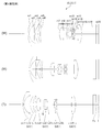
- FIG. 2 is a cross-sectional view illustrating a configuration of a zoom lens according to Example 1, where (W) indicates a wide-angle end state, (M) indicates an intermediate focal length state, and (T) indicates a position of each lens group in a telephoto end state.
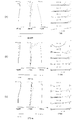
- FIG. 6 is a diagram illustrating various aberrations of the zoom lens according to Example 1 at an infinite shooting distance, where (a) shows a wide-angle end state, (b) shows an intermediate focal length state, and (c) shows a telephoto end state.
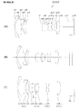
- FIG. 6 is a cross-sectional view illustrating a configuration of a zoom lens according to Example 2, where (W) indicates a wide-angle end state, (M) indicates an intermediate focal length state, and (T) indicates a position of each lens group in a telephoto end state.
- FIG. 6 is a diagram illustrating various aberrations of the zoom lens according to Example 2 at an imaging distance of infinity, where (a) shows a wide-angle end state, (b) shows an intermediate focal length state, and (c) shows a telephoto end state.
- FIG. 6 is a cross-sectional view illustrating a configuration of a zoom lens according to Example 3, where (W) indicates a wide-angle end state, (M) indicates an intermediate focal length state, and (T) indicates a position of each lens group in a telephoto end state.
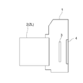
- FIG. 6 is a diagram illustrating various aberrations of the zoom lens according to Example 3 at an infinite shooting distance, where (a) shows a wide-angle end state, (b) shows an intermediate focal length state, and (c) shows a telephoto end state. It is a figure which shows the structure of the camera carrying the zoom lens which concerns on this embodiment.
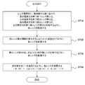
- 5 is a flowchart illustrating a method for manufacturing a zoom lens according to the present embodiment.
- the zoom lens ZL includes a first lens group G1 having negative refractive power, a second lens group G2 having positive refractive power, which are arranged in order from the object side, It has a third lens group G3 having a negative refractive power and a fourth lens group G4 having a positive refractive power, and zooming is performed by changing the interval between the lens groups.
- the negative leading positive / negative positive / negative four-group zoom is relatively free from displacement of the exit pupil toward the image side even when the total length is reduced, and is suitable for widening and miniaturization. Yes.
- the third lens group G3 includes at least one negative lens, and satisfies the following conditional expression (1).
- r1 an object-side radius of curvature of a negative lens disposed closest to the object among the negative lenses included in the third lens group G3; r2: The image-side radius of curvature of the negative lens arranged closest to the object among the negative lenses of the third lens group G3.
- Conditional expression (1) defines the shape factor (q factor) of the negative lens disposed closest to the object side in the third lens group G3. Changing this q factor means that the generated aberration changes greatly.
- the curvature of the negative lens on the image side becomes small, and off-axis aberrations, particularly astigmatism at the outermost periphery, are greatly deteriorated.
- the lower limit value of conditional expression (1) is not reached, the ray angle on the incident side becomes too acute, making it difficult to correct coma and the like.
- conditional expression (1) it is preferable to set the lower limit value of conditional expression (1) to ⁇ 4.50. In order to secure the effect of the present embodiment, it is preferable to set the lower limit value of the conditional expression (1) to ⁇ 4.00.
- the negative leading type such as the zoom lens ZL according to the present embodiment tends to increase the diameters of the first lens group G1 and the fourth lens group G4 that are far away from the stop.
- the plastic lens is disposed at least on the most image side lens (within the fourth lens group G4) of the first lens group G1 and the fourth lens group G4 having a large diameter. It is preferable. With this configuration, a small and inexpensive zoom lens can be provided.
- the plastic lens is preferably an aspheric lens. With this configuration, it is possible to satisfactorily correct various aberrations such as distortion and coma, and it is possible to ensure good optical performance.
- the most object side lens of the third lens group G3 is preferably a negative lens.
- This negative lens has a shape with a concave surface facing the image side that satisfies the conditional expression (1) as described above, and the effect of reducing the radius of curvature of the lens disposed behind the lens, and the shift sensitivity. It is possible to make the structure strong. Also, with this configuration, astigmatism and coma can be corrected well.
- the third lens group G3 includes the single negative lens. With this configuration, further miniaturization can be achieved. Further, if a positive lens is arranged behind the one negative lens (for example, in the same third lens group G3 or fourth lens group G4), it is more advantageous when correcting coma and the like. .
- the zoom lens ZL according to the present embodiment satisfies the following conditional expression (2).
- Y image height of the imaging surface
- D1w an air space between the first lens group G1 and the second lens group G2 in the wide-angle end state.
- Conditional expression (2) is to estimate the amount of movement of the second lens group G2 by defining the air gap between the first lens group G1 and the second lens group G2 in the wide-angle end state by the photographic image height. If the upper limit value of conditional expression (2) is exceeded, the second lens group G2 is configured with a strong negative power. Therefore, when the number of constituent lenses is small as in this embodiment, spherical aberration, coma aberration, Astigmatism worsens. If the lower limit value of conditional expression (2) is not reached, the second lens group G2 is configured with weak power, so that the amount of movement during zooming increases, leading to an increase in the size of the entire lens barrel. In addition, the diameter of the first lens group G1 increases, and it is difficult to correct off-axis aberrations, for example, field curvature.
- the zoom lens ZL according to the present embodiment satisfies the following conditional expression (3).
- f1 Focal length of the first lens group G1 fT: focal length in the telephoto end state of the entire system.
- Conditional expression (3) defines an appropriate range of the focal length of the first lens group G1 by the focal length in the telephoto end state of the entire system. If the upper limit of conditional expression (3) is exceeded, the power of the first lens group G1 becomes too strong, and the power of each group as a whole also becomes strong, so that various aberrations including spherical aberration cannot be corrected. Further, it is difficult to obtain a telephoto type power arrangement in the telephoto end state, which is not preferable. If the lower limit of conditional expression (3) is not reached, the amount of movement at the time of zooming increases and the front lens diameter increases, so that the entire lens barrel increases. In addition, since the variation in aberration due to zooming becomes large, it is difficult to sufficiently correct field curvature and distortion.
- the fourth lens group G4 moves to the object side upon zooming from the wide-angle end state to the telephoto end state.
- the height of the light beam incident on the fourth lens group G4 in the telephoto end state can be reduced, and the lens diameter can be reduced to reduce the cost. Further, coma can be corrected satisfactorily.
- the first lens group G1 is preferably composed of three or less lenses.
- the second lens group G2 is preferably composed of three or less lenses.
- This configuration makes it possible to reduce the size of the lens system while satisfactorily correcting spherical aberration and the like.
- the first lens group G1 preferably includes a plastic aspheric lens.
- the plastic aspherical lens in the first lens group G1 having a large lens diameter, it is possible to provide a small and inexpensive zoom lens.
- various aberrations such as curvature of field can be corrected satisfactorily by using an aspheric surface, and good optical performance can be ensured.
- the zoom lens ZL according to the present embodiment performs focusing by moving the third lens group G3 in the optical axis direction.
- the third lens group G3 which is a lens group with a small number of components, the focusing group, it is possible to reduce the size. Further, when the paraxial pupil ray passes through the third lens group G3, if this group moves back and forth on the optical axis by focusing, the field curvature and astigmatism change greatly, but the third lens used for focusing Such a short distance variation can be suppressed as much as possible because the negative lens constituting the group G3 has a concave surface directed toward the image side. Further, if a positive or negative lens is arranged behind the negative lens having the concave surface, it is advantageous for correcting various aberrations such as coma.
- the zoom lens ZL according to the present embodiment having the above-described configuration, it is possible to realize a zoom lens having excellent optical performance while reducing costs.
- the camera 1 is a so-called mirrorless camera with an interchangeable lens provided with the zoom lens ZL described above as the photographing lens 2.
- the camera 1 light from an object (not shown) that is not shown is condensed by the taking lens 2, and then on the image pickup surface of the image pickup unit 3 via an OLPF (Optical Low Pass Filter) that is not shown.
- a subject image is formed on the screen.
- the subject image is photoelectrically converted by the photoelectric conversion element provided in the imaging unit 3 to generate an image of the subject.
- This image is displayed on an EVF (Electronic view finder) 4 provided in the camera 1.
- EVF Electronic view finder
- the photographer can observe the subject via the EVF 4.
- the release button (not shown) is pressed by the photographer, the subject image generated by the imaging unit 3 is stored in a memory (not shown). In this way, the photographer can shoot the subject with the camera 1.
- the above-described zoom lens ZL mounted on the camera 1 as the photographing lens 2 has excellent optical performance while reducing costs. Therefore, according to the present camera 1, it is possible to realize a camera having excellent optical performance while reducing costs.
- a first lens group having a negative refractive power, a second lens group having a positive refractive power, and a third lens group having a negative refractive power which are arranged in order from the object side in the lens barrel.
- Each lens is arranged so as to have a fourth lens group having a positive refractive power (step ST10).
- each lens is arranged so as to perform zooming by changing the interval between the lens groups (step ST20).
- the third lens group G3 arranges each lens so as to have at least one negative lens (step ST30).
- Each lens is arranged so as to satisfy the following conditional expression (1) (step ST40).
- a plastic lens is preferably disposed as the most image side lens.
- the plastic lens preferably has an aspherical surface.
- r1 an object-side radius of curvature of a negative lens disposed closest to the object among the negative lenses included in the third lens group G3; r2: The image-side radius of curvature of the negative lens arranged closest to the object among the negative lenses of the third lens group G3.
- a meniscus negative lens L11 arranged in order from the object side and having a concave surface facing the image side
- Each lens was arranged so as to have a meniscus negative lens L12 having a concave surface facing the image side and a meniscus positive lens L13 having a convex surface facing the object side, and having negative refractive power as a whole.
- a biconvex positive lens L21 arranged in order from the object side, a cemented lens of a meniscus negative lens L22 having a concave surface facing the image side, and a biconvex positive lens L23.
- the third lens group G3 includes a biconcave negative lens L31 arranged in order from the object side, and a meniscus negative lens L32 having a concave surface directed to the image side, and has negative refractive power as a whole.
- Each lens was placed in As the fourth lens group G4, a biconvex positive lens L41 is arranged so as to have a positive refractive power as a whole.
- each lens is disposed in the lens barrel so as to satisfy the conditional expression (1) (the corresponding value of the conditional expression (1) is ⁇ 0.725).
- Tables 1 to 3 are shown below. These are tables of specifications in the first to third examples.
- each reference symbol for FIG. 1 according to the first embodiment is used independently for each embodiment in order to avoid complication of explanation due to an increase in the number of digits of the reference symbol. Therefore, even if the same reference numerals as those in the drawings according to the other embodiments are given, they are not necessarily in the same configuration as the other embodiments.
- d-line (wavelength 587.5620 nm) and g-line (wavelength 435.8350 nm) are selected as the calculation targets of the aberration characteristics.
- f is the focal length of the entire lens system
- FNo is the F number
- 2 ⁇ is the angle of view (unit: °)
- Y is the image height on the imaging surface
- Bf is the back focus (optical axis).
- the distance from the last lens surface to the paraxial image surface above, TL is the total lens length (the distance from the forefront lens to the last lens surface on the optical axis plus the back focus Bf), and the air equivalent Bf is The back focus Bf is converted to air, and the air conversion TL is obtained by adding the air conversion Bf to the total lens length TL.
- the surface number is the order of the optical surfaces from the object side along the light traveling direction
- R is the radius of curvature of each optical surface
- D is the next optical surface from each optical surface ( Or an optical surface distance to the image surface)
- ⁇ d is an Abbe number based on the d-line of the material of the optical member
- nd is a refractive index of the material of the optical member with respect to the d-line.
- the object plane is the object plane
- (variable) is the variable plane spacing
- the curvature radius “ ⁇ ” is the plane or aperture
- aperture S is the aperture stop S
- the image plane is the image plane I.
- the refractive index of air “1.000000” is omitted.
- [Variable interval data] in the table indicates the variable interval value Di in each state of the wide-angle end, the intermediate focal length, and the telephoto end.
- Di represents a variable interval between the i-th surface and the (i + 1) -th surface.
- the group number is the order of the lens groups from the object side along the direction in which the light beam travels
- the group initial surface is the surface number of the most object side of each group
- the group focal length is Indicates the focal length.
- mm is generally used for the focal length, the radius of curvature, the surface interval, and other lengths, etc. unless otherwise specified, but the optical system is proportionally enlarged or reduced. However, the same optical performance can be obtained, and the present invention is not limited to this. Further, the unit is not limited to “mm”, and other appropriate units can be used.
- the zoom lens ZL (ZL1) includes a first lens group G1 having negative refractive power and a second lens having positive refractive power, which are arranged in order from the object side.
- the lens unit includes a group G2, a third lens group G3 having negative refractive power, and a fourth lens group G4 having positive refractive power.
- the first lens group G1 includes, in order from the object side, a meniscus negative lens L11 having a concave surface facing the image side, a meniscus plastic negative lens L12 having a concave surface facing the image side, and a convex surface facing the object side. And a positive meniscus lens L13. Note that the image side surface of the negative lens L12 is aspheric.
- the second lens group G2 includes a biconvex plastic positive lens L21, an aperture stop S, a meniscus negative lens L22 having a concave surface facing the image side, and a biconvex positive lens L23 arranged in order from the object side. And a cemented lens.
- the object side surface of the positive lens L21 is an aspherical surface.
- the third lens group G3 includes a biconcave negative lens L31 arranged in order from the object side, and a meniscus plastic negative lens L32 having a concave surface directed to the image side.
- the object side surface of the negative lens L32 is aspheric.
- the fourth lens group G4 is composed of a biconvex plastic positive lens L41.
- the image side surface of the positive lens L41 is aspheric.
- a filter group FL is disposed between the fourth lens group G4 and the image plane.
- the filter group FL includes a low-pass filter or the like for cutting a spatial frequency equal to or higher than the limit resolution of the solid-state imaging device, such as a CCD disposed on the image plane I.
- the zoom lens ZL1 In the zoom lens ZL1 according to the present embodiment, all the lens groups from the first lens group G1 to the fourth lens group G4 move during zooming from the wide-angle end state (W) to the telephoto end state (T).
- the interval between the lens groups changes. Specifically, the first lens group G1 temporarily moves to the image plane side and then moves to the object side so as to draw a convex locus on the image plane side.
- the second lens group G2 moves to the object side.
- the third lens group G3 moves to the object side.
- the fourth lens group G4 moves to the object side.
- the distance between the first lens group G1 and the second lens group G2 decreases, the distance between the second lens group G2 and the third lens group G3 increases, and the third lens group G3 and the fourth lens group G4.
- Table 1 below shows the values of each item in the first example.
- Surface numbers 1 to 20 in Table 1 correspond to the optical surfaces m1 to m20 shown in FIG.
- FIG. 2 is a diagram illustrating various aberrations (spherical aberration diagram, astigmatism diagram, distortion diagram, coma aberration diagram, and chromatic aberration diagram of magnification) at the photographing distance infinity of the zoom lens ZL1 according to the first example.
- FNO represents the F number
- Y represents the image height
- d indicates an aberration curve at the d-line
- g indicates an aberration curve at the g-line.
- the spherical aberration diagram shows the F-number corresponding to the maximum aperture
- the astigmatism diagram and the distortion diagram show the maximum value of the image height Y
- the coma diagram shows the value of each image height.
- a solid line indicates a sagittal image plane
- a broken line indicates a meridional image plane.
- the zoom lens ZL1 according to the present example has excellent optical performance with various aberrations corrected well from the wide-angle end state to the telephoto end state.
- the zoom lens ZL (ZL2) according to the second example includes a first lens group G1 having negative refractive power and a second lens having positive refractive power, which are arranged in order from the object side.
- the lens unit includes a group G2, a third lens group G3 having negative refractive power, and a fourth lens group G4 having positive refractive power.
- the first lens group G1 includes a meniscus plastic negative lens L11 having a concave surface facing the image side, a biconcave plastic negative lens L12, and a meniscus shape having a convex surface facing the object side, which are arranged in order from the object side. And a positive lens L13. Note that the image side surface of the negative lens L11 is aspheric.
- the second lens group G2 includes a biconvex plastic positive lens L21, an aperture stop S, a meniscus negative lens L22 having a concave surface facing the image side, and a biconvex positive lens L23 arranged in order from the object side. And a cemented lens.
- the object side surface of the positive lens L21 is an aspherical surface.
- the third lens group G3 includes a biconcave plastic negative lens L31. Note that both side surfaces of the positive lens L31 are aspheric surfaces.
- the fourth lens group G4 includes a meniscus plastic positive lens L41 having a convex surface directed toward the image side. Note that both side surfaces of the positive lens L41 are aspheric surfaces.
- a filter group FL is disposed between the fourth lens group G4 and the image plane.
- the filter group FL includes a low-pass filter or the like for cutting a spatial frequency equal to or higher than the limit resolution of the solid-state imaging device, such as a CCD disposed on the image plane I.
- the zoom lens ZL2 In the zoom lens ZL2 according to the present embodiment, all the lens groups from the first lens group G1 to the fourth lens group G4 move during zooming from the wide-angle end state (W) to the telephoto end state (T).
- the interval between the lens groups changes. Specifically, the first lens group G1 temporarily moves to the image plane side and then moves to the object side so as to draw a convex locus on the image plane side.
- the second lens group G2 moves to the object side.
- the third lens group G3 moves to the object side.
- the fourth lens group G4 moves to the object side.
- the distance between the first lens group G1 and the second lens group G2 decreases, the distance between the second lens group G2 and the third lens group G3 increases, and the third lens group G3 and the fourth lens group G4.
- Table 2 shows the values of each item in the second example.
- Surface numbers 1 to 18 in Table 2 correspond to the optical surfaces m1 to m18 shown in FIG.
- FIG. 4 is a diagram showing various aberrations (spherical aberration diagram, astigmatism diagram, distortion diagram, coma diagram, and chromatic aberration diagram of magnification) at the photographing distance infinity of the zoom lens ZL2 according to the second example.
- the zoom lens ZL2 according to the present example has excellent optical performance with various aberrations corrected well from the wide-angle end state to the telephoto end state.
- the zoom lens ZL (ZL3) according to the third example includes a first lens group G1 having negative refractive power and a second lens having positive refractive power, which are arranged in order from the object side.
- the lens unit includes a group G2, a third lens group G3 having negative refractive power, and a fourth lens group G4 having positive refractive power.
- the first lens group G1 is arranged in order from the object side, the meniscus negative lens L11 having a concave surface facing the image side, the meniscus negative lens L12 having a concave surface facing the image side, and a convex surface facing the object side. And a meniscus positive lens L13. Note that the image side surface of the negative lens L12 is aspheric.
- the second lens group G2 is arranged in order from the object side, and has a meniscus positive lens L21 having a convex surface facing the object side, an aperture stop S, a biconvex positive lens L22, and a concave surface facing the object side. It comprises a meniscus negative lens L23.
- the object side surface of the positive lens L21 is an aspherical surface.
- the object side surface of the positive lens L22 is aspheric.
- the third lens group G3 includes a biconcave negative lens L31 arranged in order from the object side, and a meniscus positive lens L32 having a convex surface directed toward the object side.
- the fourth lens group G4 is composed of a biconvex plastic positive lens L41.
- the object side surface of the positive lens L41 is aspheric.
- a filter group FL is disposed between the fourth lens group G4 and the image plane.
- the filter group FL includes a low-pass filter or the like for cutting a spatial frequency equal to or higher than the limit resolution of the solid-state imaging device, such as a CCD disposed on the image plane I.
- the zoom lens ZL3 In the zoom lens ZL3 according to the present embodiment, all the lens groups from the first lens group G1 to the fourth lens group G4 move during zooming from the wide-angle end state (W) to the telephoto end state (T).
- the interval between the lens groups changes. Specifically, the first lens group G1 temporarily moves to the image plane side and then moves to the object side so as to draw a convex locus on the image plane side.
- the second lens group G2 moves to the object side.
- the third lens group G3 moves to the object side.
- the fourth lens group G4 moves to the object side. At this time, the distance between the first lens group G1 and the second lens group G2 decreases, the distance between the second lens group G2 and the third lens group G3 decreases, and the third lens group G3 and the fourth lens group G4.
- Table 3 shows the values of each item in the third example.
- Surface numbers 1 to 21 in Table 3 correspond to the optical surfaces m1 to m21 shown in FIG.
- FIG. 6 is a diagram illustrating various aberrations (spherical aberration diagram, astigmatism diagram, distortion diagram, coma diagram, and chromatic aberration diagram of magnification) at the photographing distance infinity of the zoom lens ZL3 according to Example 3, and (a) Is the wide-angle end state, (b) is the intermediate focal length state, and (c) is the telephoto end state.
- various aberrations spherical aberration diagram, astigmatism diagram, distortion diagram, coma diagram, and chromatic aberration diagram of magnification
- the zoom lens ZL3 according to the present example has excellent optical performance with various aberrations corrected well from the wide-angle end state to the telephoto end state.
- a four-group configuration is shown, but it can also be applied to other group configurations. Further, a configuration in which a lens or a lens group is added to the most object side, or a configuration in which a lens or a lens group is added to the most image side may be used.
- the lens group refers to a portion having at least one lens separated by an air interval that changes during focusing or zooming.
- a single lens group, a plurality of lens groups, or a partial lens group may be moved in the optical axis direction so as to perform focusing from an object at infinity to a near object.
- This focusing lens group can be applied to autofocus, and is also suitable for driving a motor for autofocus (using an ultrasonic motor or the like).
- the third lens group G3 is preferably a focusing lens group.
- the lens group or the partial lens group is moved so as to have a component in a direction perpendicular to the optical axis, or is rotated (oscillated) in an in-plane direction including the optical axis.
- a vibration-proof lens group that corrects image blur caused by camera shake may be used.
- the lens surface may be formed as a spherical surface, a flat surface, or an aspheric surface.
- the lens surface is a spherical surface or a flat surface, lens processing and assembly adjustment are facilitated, and optical performance deterioration due to processing and assembly adjustment errors can be prevented. Further, even when the image plane is deviated, it is preferable because there is little deterioration in drawing performance.
- the lens surface is an aspheric surface, the aspheric surface is an aspheric surface by grinding, a glass mold aspheric surface made of glass with an aspheric shape, or a composite aspheric surface made of resin with an aspheric shape on the glass surface. Any aspherical surface may be used.
- the lens surface may be a diffractive surface, and the lens may be a gradient index lens (GRIN lens) or a plastic lens.
- GRIN lens gradient index lens
- the aperture stop S is preferably disposed in the second lens group G2, but instead of providing a member as an aperture stop, a role of the lens frame is used instead. Also good.
- each lens surface may be provided with an antireflection film having high transmittance in a wide wavelength range in order to reduce flare and ghost and achieve high contrast and high optical performance. Good.
Landscapes
- Physics & Mathematics (AREA)
- General Physics & Mathematics (AREA)
- Optics & Photonics (AREA)
- Lenses (AREA)
Abstract
物体側より順に並んだ、負の屈折力を有する第1レンズ群(G1)と、正の屈折力を有する第2レンズ群(G2)と、負の屈折力を有する第3レンズ群(G3)と、正の屈折力を有する第4レンズ群(G4)とを有し、各レンズ群の間隔が変化することによって変倍を行い、第3レンズ群(G3)は、少なくとも1枚の負レンズを有し、次の条件式(1)を満足する。 -5.00 < (r2+r1)/(r2-r1) < 0.30 …(1) 但し、r1:第3レンズ群(G3)が有する負レンズのうち、最も物体側に配置される負レンズの物体側曲率半径、r2:第3レンズ群(G3)が有する負レンズのうち、最も物体側に配置される負レンズの像側曲率半径。
Description
本発明は、ズームレンズ、光学機器及びズームレンズの製造方法に関する。
従来から、負先行のズームレンズが提案されている(例えば、特許文献1を参照)。
ズームレンズに対する要求は年々厳しさを増しており、さらなる高性能化が求められている。
本発明は、このような問題に鑑みてなされたものであり、優れた光学性能を有するズームレンズ、光学機器及びズームレンズの製造方法を提供することを目的とする。
このような目的を達成するため、本発明に係るズームレンズは、物体側より順に並んだ、負の屈折力を有する第1レンズ群と、正の屈折力を有する第2レンズ群と、負の屈折力を有する第3レンズ群と、正の屈折力を有する第4レンズ群とを有し、各レンズ群の間隔が変化することによって変倍を行い、前記第3レンズ群は、少なくとも1枚の負レンズを有し、次の条件式を満足する。
-5.00 < (r2+r1)/(r2-r1) < 0.30
但し、
r1:前記第3レンズ群が有する負レンズのうち、最も物体側に配置される負レンズの物体側曲率半径、
r2:前記第3レンズ群が有する負レンズのうち、最も物体側に配置される負レンズの像側曲率半径。
但し、
r1:前記第3レンズ群が有する負レンズのうち、最も物体側に配置される負レンズの物体側曲率半径、
r2:前記第3レンズ群が有する負レンズのうち、最も物体側に配置される負レンズの像側曲率半径。
本発明に係るズームレンズにおいて、最も像側のレンズは、プラスチックレンズであることが好ましい。
本発明に係るズームレンズにおいて、前記プラスチックレンズは、非球面を有することが好ましい。
本発明に係るズームレンズにおいて、前記第3レンズ群の最も物体側のレンズは、負レンズであることが好ましい。
本発明に係るズームレンズは、次の条件式を満足していることが好ましい。
0.38 < Y/D1w < 0.80
但し、
Y:撮像面の像高、
D1w:広角端状態における前記第1レンズ群と前記第2レンズ群との空気間隔。
但し、
Y:撮像面の像高、
D1w:広角端状態における前記第1レンズ群と前記第2レンズ群との空気間隔。
本発明に係るズームレンズは、次の条件式を満足していることが好ましい。
0.30 < (-f1)/fT < 0.70
但し、
f1:前記第1レンズ群の焦点距離、
fT:全系の望遠端状態における焦点距離。
但し、
f1:前記第1レンズ群の焦点距離、
fT:全系の望遠端状態における焦点距離。
本発明に係るズームレンズにおいて、広角端状態から望遠端状態への変倍に際して、前記第4レンズ群は物体側へ移動することが好ましい。
本発明に係るズームレンズにおいて、前記第1レンズ群は、3枚以下のレンズで構成されていることが好ましい。
本発明に係るズームレンズにおいて、前記第2レンズ群は、3枚以下のレンズで構成されていることが好ましい。
本発明に係るズームレンズにおいて、前記第3レンズ群は、1枚の負レンズで構成されていることが好ましい。
本発明に係るズームレンズにおいて、前記第1レンズ群は、プラスチック非球面レンズを有することが好ましい。
本発明に係るズームレンズにおいて、前記第3レンズ群を移動させることにより、合焦を行うことが好ましい。
本発明に係る光学機器は、上述のズームレンズのいずれかを搭載する。
本発明に係るズームレンズの製造方法は、物体側より順に並んだ、負の屈折力を有する第1レンズ群と、正の屈折力を有する第2レンズ群と、負の屈折力を有する第3レンズ群と、正の屈折力を有する第4レンズ群とを有するズームレンズの製造方法であって、各レンズ群の間隔が変化することによって変倍を行い、前記第3レンズ群は、少なくとも1枚の負レンズを有し、次の条件式を満足するように、レンズ鏡筒内に各レンズを配置する。
-5.00 < (r2+r1)/(r2-r1) < 0.30
但し、
r1:前記第3レンズ群が有する負レンズのうち、最も物体側に配置される負レンズの物体側曲率半径、
r2:前記第3レンズ群が有する負レンズのうち、最も物体側に配置される負レンズの像側曲率半径。
但し、
r1:前記第3レンズ群が有する負レンズのうち、最も物体側に配置される負レンズの物体側曲率半径、
r2:前記第3レンズ群が有する負レンズのうち、最も物体側に配置される負レンズの像側曲率半径。
本発明によれば、優れた光学性能を有するズームレンズ、光学機器及びズームレンズの製造方法を提供することができる。
以下、実施形態について、図面を参照しながら説明する。本実施形態に係るズームレンズZLは、図1に示すように、物体側より順に並んだ、負の屈折力を有する第1レンズ群G1と、正の屈折力を有する第2レンズ群G2と、負の屈折力を有する第3レンズ群G3と、正の屈折力を有する第4レンズ群G4とを有し、各レンズ群の間隔が変化することによって変倍を行う。
負先行型の負正負正の4群ズームは、負正2群ズームに比べて、全長を小型化しても比較的射出瞳が像側へ変位することがなく、広角化、小型化に向いている。
上記構成のもと、本実施形態に係るズームレンズZLにおいては、第3レンズ群G3は、少なくとも1枚の負レンズを有し、次の条件式(1)を満足する。
-5.00 < (r2+r1)/(r2-r1) < 0.30 …(1)
但し、
r1:第3レンズ群G3が有する負レンズのうち、最も物体側に配置される負レンズの物体側曲率半径、
r2:第3レンズ群G3が有する負レンズのうち、最も物体側に配置される負レンズの像側曲率半径。
但し、
r1:第3レンズ群G3が有する負レンズのうち、最も物体側に配置される負レンズの物体側曲率半径、
r2:第3レンズ群G3が有する負レンズのうち、最も物体側に配置される負レンズの像側曲率半径。
条件式(1)は、第3レンズ群G3内で最も物体側に配置された負レンズの形状因子(qファクター)を規定するものである。このqファクターを変えることは、発生する収差が大きく変化することを意味する。条件式(1)の上限値を上回ると、負レンズの像側の曲率が小さくなり、軸外収差、特に最外周での非点収差が大きく劣化する。条件式(1)の下限値を下回ると、入射側の光線角が鋭角になりすぎ、コマ収差などの補正が困難となる。
本実施形態の効果を確実なものとするために、条件式(1)の上限値を0.25とすることが好ましい。本実施形態の効果をより確実なものとするために、条件式(1)の上限値を0.20とすることが好ましい。
本実施形態の効果を確実なものとするために、条件式(1)の下限値を-4.50とすることが好ましい。本実施形態の効果をより確実なものとするために、条件式(1)の下限値を-4.00とすることが好ましい。
本実施形態に係るズームレンズZLのような負先行型のタイプは、絞りから距離の離れた、第1レンズ群G1や第4レンズ群G4の径が大きくなる傾向がある。
そこで、本実施形態に係るズームレンズZLは、径が大きい第1レンズ群G1と第4レンズ群G4のうち、少なくとも(第4レンズ群G4内の)最も像側のレンズにプラスチックレンズを配置することが好ましい。この構成により、小型で、安価なズームレンズを提供することができる。
また、前記プラスチックレンズは、非球面レンズであることが好ましい。この構成により、歪曲収差、コマ収差など諸収差を良好に補正することが可能となり、良好な光学性能も確保することができる。
本実施形態に係るズームレンズZLにおいて、第3レンズ群G3の最も物体側のレンズは、負レンズであることが好ましい。
この負レンズは、上述のように条件式(1)を満足する像側に凹面を向けた形状を有しており、該レンズの後方に配置するレンズの曲率半径を緩くする効果や、シフト感度に強い構成とすることが可能である。また、この構成により、非点収差、コマ収差を良好に補正することができる。
本実施形態に係るズームレンズZLにおいて、第3レンズ群G3は、前記負レンズ1枚で構成されていることが好ましい。この構成により、さらに小型化も達成することが可能となる。また、前記1枚の負レンズの後方(例えば、同じ第3レンズ群G3内、又は第4レンズ群G4内)に、正レンズを配置すれば、コマ収差等の補正を行う際により有利となる。
本実施形態に係るズームレンズZLは、次の条件式(2)を満足していることが好ましい。
0.38 < Y/D1w < 0.80 …(2)
但し、
Y:撮像面の像高、
D1w:広角端状態における第1レンズ群G1と第2レンズ群G2との空気間隔。
但し、
Y:撮像面の像高、
D1w:広角端状態における第1レンズ群G1と第2レンズ群G2との空気間隔。
条件式(2)は、広角端状態における第1レンズ群G1と第2レンズ群G2との空気間隔を撮影像高で規定することにより、第2レンズ群G2の移動量を推し量るものである。条件式(2)の上限値を上回ると、第2レンズ群G2が強い負のパワーで構成されることになるため、本実施形態のように構成レンズ枚数が少ない場合、球面収差、コマ収差、非点収差が悪化する。条件式(2)の下限値を下回ると、第2レンズ群G2が弱いパワーで構成されることになるため、変倍時の移動量が増し、鏡筒全体の大型化を招く。また、第1レンズ群G1の径が大きくなり、軸外収差、例えば像面湾曲が補正しづらくなる。
本実施形態の効果を確実なものとするために、条件式(2)の上限値を0.70とすることが好ましい。本実施形態の効果をより確実なものとするために、条件式(2)の上限値を0.60とすることが好ましい。
本実施形態に係るズームレンズZLは、次の条件式(3)を満足していることが好ましい。
0.30 < (-f1)/ fT < 0.70 …(3)
但し、
f1:第1レンズ群G1の焦点距離、
fT:全系の望遠端状態における焦点距離。
但し、
f1:第1レンズ群G1の焦点距離、
fT:全系の望遠端状態における焦点距離。
条件式(3)は、第1レンズ群G1の焦点距離の適切な範囲を、全系の望遠端状態における焦点距離で規定するものである。条件式(3)の上限値を上回ると、第1レンズ群G1のパワーが強くなりすぎ、全体として各群のパワーも強まるため、球面収差をはじめとする諸収差の補正ができない。また、望遠端状態でテレフォトタイプのパワー配置を取りづらくなるため、好ましくない。条件式(3)の下限値を下回ると、変倍時の移動量が増し、前玉径が大きくなるため、鏡筒全体が大型化する。また、変倍による収差の変動が大きくなるため、像面湾曲や歪曲収差の十分な補正が困難となる。
本実施形態の効果を確実なものとするために、条件式(3)の上限値を0.65とすることが好ましい。本実施形態の効果をより確実なものとするために、条件式(3)の上限値を0.60とすることが好ましい。
本実施形態の効果を確実なものとするために、条件式(3)の下限値を0.35とすることが好ましい。本実施形態の効果をより確実なものとするために、条件式(3)の下限値を0.40とすることが好ましい。
本実施形態に係るズームレンズZLにおいては、広角端状態から望遠端状態への変倍に際して、第4レンズ群G4は物体側へ移動することが好ましい。
この構成により、望遠端状態における第4レンズ群G4に入射する光線高さを下げることができ、レンズ径を縮小してコストダウンを図ることができる。また、コマ収差を良好に補正することができる。
本実施形態に係るズームレンズZLにおいて、第1レンズ群G1は、3枚以下のレンズで構成されていることが好ましい。
この構成により、レンズ径の大きな第1レンズ群の構成枚数を少なくすることで、小型化、低コスト化を図ることができる。また、該レンズ群G1から射出する光線高さを下げることができ、コマ収差、像面湾曲など、軸外の諸収差を良好に補正することができる。
本実施形態に係るズームレンズZLにおいて、第2レンズ群G2は、3枚以下のレンズで構成されていることが好ましい。
この構成により、球面収差などを良好に補正しながら、レンズ系の小型化を達成することができる。
本実施形態に係るズームレンズZLにおいて、第1レンズ群G1は、プラスチック非球面レンズを有することが好ましい。
本実施形態のように、レンズ径が大きい第1レンズ群G1にプラスチック非球面レンズを配置することで、小型で、安価なズームレンズを提供することができる。また、非球面を利用して、像面湾曲など、諸収差を良好に補正することが可能となり、良好な光学性能も確保することができる。
本実施形態に係るズームレンズZLは、第3レンズ群G3を光軸方向に移動させることにより、合焦(フォーカシング)を行うことが好ましい。
このように構成枚数が少ないレンズ群である、第3レンズ群G3を合焦群とすることで、小型化を図ることができる。また、近軸瞳光線が第3レンズ群G3を通過する際に、フォーカシングによってこの群が光軸上を前後すると、像面湾曲や非点収差が大きく変化するが、合焦に用いる第3レンズ群G3を構成する負レンズが像側に凹面を向けていることにより、このような近距離変動をできるだけ抑えることができる。さらに、前記凹面を持つ負レンズの後方に、正又は負レンズを配置すれば、コマ収差等の諸収差の補正により有利となる。
以上のような構成を備える本実施形態に係るズームレンズZLによれば、低コスト化を図りつつ、優れた光学性能を有するズームレンズを実現することができる。
次に、図7を参照しながら、上述のズームレンズZLを搭載したカメラ(光学機器)について説明する。カメラ1は、図7に示すように、撮影レンズ2として上述のズームレンズZLを備えたレンズ交換式の所謂ミラーレスカメラである。このカメラ1において、不図示の物体(被写体)からの光は、撮影レンズ2で集光されて、不図示のOLPF(Optical low pass filter:光学ローパスフィルタ)を介して撮像部3の撮像面上に被写体像を形成する。そして、撮像部3に設けられた光電変換素子によって被写体像が光電変換されて被写体の画像が生成される。この画像は、カメラ1に設けられたEVF(Electronic view finder:電子ビューファインダ)4に表示される。これにより撮影者は、EVF4を介して被写体を観察することができる。また、撮影者によって不図示のレリーズボタンが押されると、撮像部3で生成された被写体の画像が不図示のメモリに記憶される。このようにして、撮影者は本カメラ1による被写体の撮影を行うことができる。
ここで、本カメラ1に撮影レンズ2として搭載した上述のズームレンズZLは、低コスト化を図りつつ、優れた光学性能を備えている。したがって、本カメラ1によれば、低コスト化を図りつつ、優れた光学性能を有するカメラを実現することができる。
なお、クイックリターンミラーを有し、ファインダ光学系によって被写体を観察する一眼レフタイプのカメラに、上述のズームレンズZLを搭載した場合でも、上記カメラ1と同様の効果を奏することができる。また、ビデオカメラに、上述のズームレンズZLを搭載した場合でも、上記カメラ1と同様の効果を奏することができる。
続いて、図8を参照しながら、上述のズームレンズZLの製造方法について概説する。まず、レンズ鏡筒内に、物体側より順に並んだ、負の屈折力を有する第1レンズ群と、正の屈折力を有する第2レンズ群と、負の屈折力を有する第3レンズ群と、正の屈折力を有する第4レンズ群とを有するように、各レンズを配置する(ステップST10)。このとき、各レンズ群の間隔が変化することによって変倍を行うように、各レンズを配置する(ステップST20)。第3レンズ群G3は、少なくとも1枚の負レンズを有するように、各レンズを配置する(ステップST30)。次の条件式(1)を満足するように、各レンズを配置する(ステップST40)。なお、最も像側のレンズとして、プラスチックレンズを配置することが好ましい。また、前記プラスチックレンズは、非球面を有することが好ましい。
-5.00 < (r2+r1)/(r2-r1) < 0.30 …(1)
但し、
r1:第3レンズ群G3が有する負レンズのうち、最も物体側に配置される負レンズの物体側曲率半径、
r2:第3レンズ群G3が有する負レンズのうち、最も物体側に配置される負レンズの像側曲率半径。
但し、
r1:第3レンズ群G3が有する負レンズのうち、最も物体側に配置される負レンズの物体側曲率半径、
r2:第3レンズ群G3が有する負レンズのうち、最も物体側に配置される負レンズの像側曲率半径。
本実施形態におけるレンズ配置の一例を挙げると、図1に示すズームレンズZLでは、第1レンズ群G1として、物体側から順に並んだ、像側に凹面を向けたメニスカス形状の負レンズL11と、像側に凹面を向けたメニスカス形状の負レンズL12と、物体側に凸面を向けたメニスカス形状の正レンズL13とを有し、全体として負の屈折力を有するように、各レンズを配置した。第2レンズ群G2として、物体側から順に並んだ、両凸形状の正レンズL21と、像側に凹面を向けたメニスカス形状の負レンズL22と両凸形状の正レンズL23との接合レンズとを有し、全体として正の屈折力を有するように、各レンズを配置した。第3レンズ群G3として、物体側から順に並んだ、両凹形状の負レンズL31と、像側に凹面を向けたメニスカス形状の負レンズL32とを有し、全体として負の屈折力を有するように、各レンズを配置した。第4レンズ群G4として、両凸形状の正レンズL41を配置し、全体として正の屈折力を持つように構成した。また、条件式(1)を満足するように、各レンズを鏡筒内に配置した(条件式(1)の対応値は-0.725)。
上記の製造方法によれば、低コスト化を図りつつ、優れた光学性能を有するズームレンズを製造することができる。
これより本実施形態に係る各実施例について、図面に基づいて説明する。以下に、表1~表3を示すが、これらは第1実施例~第3実施例における各諸元の表である。
なお、第1実施例に係る図1に対する各参照符号は、参照符号の桁数の増大による説明の煩雑化を避けるため、実施例ごとに独立して用いている。ゆえに、他の実施例に係る図面と共通の参照符号を付していても、それらは他の実施例とは必ずしも共通の構成ではない。
各実施例では収差特性の算出対象として、d線(波長587.5620nm)、g線(波長435.8350nm)を選んでいる。
表中の[全体諸元]において、fはレンズ全系の焦点距離、FNoはFナンバー、2ωは画角(単位:°)、Yは撮像面での像高、Bfはバックフォーカス(光軸上でのレンズ最終面から近軸像面までの距離)、TLはレンズ全長(光軸上でのレンズ最前面からレンズ最終面までの距離にバックフォーカスBfを加えたもの)、空気換算BfはバックフォーカスBfを空気換算したもの、空気換算TLはレンズ全長TLに空気換算Bfを加えたものを示す。
表中の[レンズ諸元]において、面番号は光線の進行する方向に沿った物体側からの光学面の順序、Rは各光学面の曲率半径、Dは各光学面から次の光学面(又は像面)までの光軸上の距離である面間隔、νdは光学部材の材質のd線を基準とするアッベ数、ndは光学部材の材質のd線に対する屈折率を示す。物面は物体面、(可変)は可変の面間隔、曲率半径の「∞」は平面又は開口、(絞りS)は開口絞りS、像面は像面Iをそれぞれ示す。空気の屈折率「1.000000」は省略する。光学面が非球面である場合には、面番号に*印を付し、曲率半径Rの欄には近軸曲率半径を示す。
表中の[非球面データ]には、[レンズ諸元]に示した非球面について、その形状を次式(a)で示す。X(y)は非球面の頂点における接平面から高さyにおける非球面上の位置までの光軸方向に沿った距離を、Rは基準球面の曲率半径(近軸曲率半径)を、κは円錐定数を、Aiは第i次の非球面係数を示す。「E-n」は、「×10-n」を示す。例えば、1.234E-05=1.234×10⁻⁵である。
X(y)=(y2/R)/{1+(1-κ×y2/R2)1/2}+A4×y4+A6×y6+A8×y8+A10×y10 …(a)
表中の[可変間隔データ]において、広角端、中間焦点距離、望遠端の各状態における可変間隔の値Diを示す。なお、Diは、第i面と第(i+1)面の可変間隔を示す。
表中の[レンズ群データ]において、群番号は光線の進行する方向に沿った物体側からのレンズ群の順序、群初面は各群の最も物体側の面番号、群焦点距離は各群の焦点距離を示す。
表中の[条件式]には、上記の条件式(1)~(3)に対応する値を示す。
以下、全ての諸元値において、掲載されている焦点距離、曲率半径、面間隔、その他の長さ等は、特記のない場合一般に「mm」が使われるが、光学系は比例拡大又は比例縮小しても同等の光学性能が得られるので、これに限られるものではない。また、単位は「mm」に限定されることなく、他の適当な単位を用いることが可能である。
ここまでの表の説明は全ての実施例において共通であり、以下での説明を省略する。
(第1実施例)
第1実施例について、図1,図2及び表1を用いて説明する。第1実施例に係るズームレンズZL(ZL1)は、図1に示すように、物体側から順に並んだ、負の屈折力を有する第1レンズ群G1と、正の屈折力を有する第2レンズ群G2と、負の屈折力を有する第3レンズ群G3と、正の屈折力を有する第4レンズ群G4とから構成される。
第1実施例について、図1,図2及び表1を用いて説明する。第1実施例に係るズームレンズZL(ZL1)は、図1に示すように、物体側から順に並んだ、負の屈折力を有する第1レンズ群G1と、正の屈折力を有する第2レンズ群G2と、負の屈折力を有する第3レンズ群G3と、正の屈折力を有する第4レンズ群G4とから構成される。
第1レンズ群G1は、物体側から順に並んだ、像側に凹面を向けたメニスカス形状の負レンズL11と、像側に凹面を向けたメニスカス形状のプラスチック負レンズL12と、物体側に凸面を向けたメニスカス形状の正レンズL13とから構成される。なお、負レンズL12の像側面は、非球面である。
第2レンズ群G2は、物体側から順に並んだ、両凸形状のプラスチック正レンズL21と、開口絞りSと、像側に凹面を向けたメニスカス形状の負レンズL22と両凸形状の正レンズL23との接合レンズとから構成される。なお、正レンズL21の物体側面は、非球面である。
第3レンズ群G3は、物体側から順に並んだ、両凹形状の負レンズL31と、像側に凹面を向けたメニスカス形状のプラスチック負レンズL32とから構成される。なお、負レンズL32の物体側面は、非球面である。
第4レンズ群G4は、両凸形状のプラスチック正レンズL41から構成される。なお、正レンズL41の像側面は、非球面である。
第4レンズ群G4と像面との間に、フィルタ群FLが配置されている。フィルタ群FLは、像面Iに配設されるCCD等、固体撮像素子の限界解像以上の空間周波数をカットするためのローパスフィルタ等で構成されている。
本実施例に係るズームレンズZL1は、広角端状態(W)から望遠端状態(T)への変倍に際して、第1レンズ群G1から第4レンズ群G4までの全てのレンズ群が移動し、各レンズ群の間隔が変化する。具体的には、第1レンズ群G1は、像面側に凸の軌跡を描くように、一旦像面側に移動し、その後物体側へ移動する。第2レンズ群G2は、物体側へ移動する。第3レンズ群G3は、物体側へ移動する。第4レンズ群G4は、物体側へ移動する。このとき、第1レンズ群G1と第2レンズ群G2との間隔が減少し、第2レンズ群G2と第3レンズ群G3との間隔は増加し、第3レンズ群G3と第4レンズ群G4との間隔が増加する。
下記の表1に、第1実施例における各諸元の値を示す。表1における面番号1~20が、図1に示すm1~m20の各光学面に対応している。
(表1)
[全体諸元]
ズーム比 2.825
広角端 中間焦点 望遠端
f 10.3002 17.0086 29.0997
FNo 3.60 4.39 5.99
2ω 80.7 51.8 31.1
Y 8.19 8.19 8.19
Bf 2.11 2.11 2.11
TL 62.4606 61.1215 66.8908
空気換算Bf 1.1594 1.1594 1.1594
空気換算TL 61.5100 60.1709 65.9402
[レンズ諸元]
面番号 R D νd nd
物面 ∞
1 20.0000 1.0000 60.10 1.640495
2 8.9619 4.6964
3 309.4286 0.8000 56.00 1.531100
*4 9.9201 2.7339
5 18.0992 1.7375 23.80 1.846660
6 31.5760 D6(可変)
*7 11.1478 3.4707 56.00 1.531100
8 -83.9533 2.5503
9 ∞ 0.2000 (絞りS)
10 13.2901 1.0752 32.17 1.850249
11 6.1850 2.3777 65.57 1.599501
12 -39.5901 D12(可変)
13 -110.0885 0.8000 40.60 1.853702
14 17.5821 0.4457
*15 48.0807 0.8210 56.00 1.531100
16 28.2564 D16(可変)
17 107.4903 3.5118 56.00 1.531100
*18 -20.1969 D18(可変)
19 ∞ 2.7900 63.88 1.516800
20 ∞ 2.1100
像面 ∞
[非球面データ]
面番号 κ A4 A6 A8 A10
4 1.0000 -1.39209E-04 -1.18491E-06 2.24604E-09 -1.85990E-10
7 1.0000 -6.90561E-05 -5.48000E-07 1.06880E-08 -3.48544E-10
15 1.0000 -2.76310E-04 2.49323E-07 0.00000E+00 0.00000E+00
18 1.0000 1.72522E-06 -2.38147E-08 1.15876E-09 -9.68223E-12
[可変間隔データ]
可変間隔 広角端 中間焦点 望遠端
D6 17.0011 7.6289 1.0075
D12 1.4412 2.7127 6.1224
D16 2.9906 6.3515 13.2549
D18 9.9075 13.3082 15.3858
[レンズ群データ]
群番号 群初面 群焦点距離
G1 1 -14.08697
G2 7 12.21202
G3 13 -15.40884
G4 17 32.32166
[条件式]
条件式(1) (r2+r1)(r2-r1) = -0.725
条件式(2) Y/D1w = 0.482
条件式(3) (-f1)/fT= 0.484
[全体諸元]
ズーム比 2.825
広角端 中間焦点 望遠端
f 10.3002 17.0086 29.0997
FNo 3.60 4.39 5.99
2ω 80.7 51.8 31.1
Y 8.19 8.19 8.19
Bf 2.11 2.11 2.11
TL 62.4606 61.1215 66.8908
空気換算Bf 1.1594 1.1594 1.1594
空気換算TL 61.5100 60.1709 65.9402
[レンズ諸元]
面番号 R D νd nd
物面 ∞
1 20.0000 1.0000 60.10 1.640495
2 8.9619 4.6964
3 309.4286 0.8000 56.00 1.531100
*4 9.9201 2.7339
5 18.0992 1.7375 23.80 1.846660
6 31.5760 D6(可変)
*7 11.1478 3.4707 56.00 1.531100
8 -83.9533 2.5503
9 ∞ 0.2000 (絞りS)
10 13.2901 1.0752 32.17 1.850249
11 6.1850 2.3777 65.57 1.599501
12 -39.5901 D12(可変)
13 -110.0885 0.8000 40.60 1.853702
14 17.5821 0.4457
*15 48.0807 0.8210 56.00 1.531100
16 28.2564 D16(可変)
17 107.4903 3.5118 56.00 1.531100
*18 -20.1969 D18(可変)
19 ∞ 2.7900 63.88 1.516800
20 ∞ 2.1100
像面 ∞
[非球面データ]
面番号 κ A4 A6 A8 A10
4 1.0000 -1.39209E-04 -1.18491E-06 2.24604E-09 -1.85990E-10
7 1.0000 -6.90561E-05 -5.48000E-07 1.06880E-08 -3.48544E-10
15 1.0000 -2.76310E-04 2.49323E-07 0.00000E+00 0.00000E+00
18 1.0000 1.72522E-06 -2.38147E-08 1.15876E-09 -9.68223E-12
[可変間隔データ]
可変間隔 広角端 中間焦点 望遠端
D6 17.0011 7.6289 1.0075
D12 1.4412 2.7127 6.1224
D16 2.9906 6.3515 13.2549
D18 9.9075 13.3082 15.3858
[レンズ群データ]
群番号 群初面 群焦点距離
G1 1 -14.08697
G2 7 12.21202
G3 13 -15.40884
G4 17 32.32166
[条件式]
条件式(1) (r2+r1)(r2-r1) = -0.725
条件式(2) Y/D1w = 0.482
条件式(3) (-f1)/fT= 0.484
表1から、本実施例に係るズームレンズZL1は、条件式(1)~(3)を満たすことが分かる。
図2は、第1実施例に係るズームレンズZL1の撮影距離無限遠における諸収差図(球面収差図、非点収差図、歪曲収差図、コマ収差図及び倍率色収差図)であり、(a)は広角端状態、(b)は中間焦点距離状態、(c)は望遠端状態を示す。
各収差図において、FNOはFナンバー、Yは像高を示す。dはd線、gはg線における収差曲線を示す。また、記載のないものは、d線における収差を示す。球面収差図では最大口径に対応するFナンバーを示し、非点収差図、歪曲収差図では像高Yの最大値を示し、コマ収差図では各像高の値を示す。また、非点収差図において、実線はサジタル像面、破線はメリジオナル像面を示す。
ここまでの収差図の説明は、全ての実施例において共通であり、以下での説明を省略する。
各収差図から明らかなように、本実施例に係るズームレンズZL1は、広角端状態から望遠端状態に亘って諸収差が良好に補正され、優れた光学性能を有することが分かる。
(第2実施例)
第2実施例について、図3,図4及び表2を用いて説明する。第2実施例に係るズームレンズZL(ZL2)は、図3に示すように、物体側から順に並んだ、負の屈折力を有する第1レンズ群G1と、正の屈折力を有する第2レンズ群G2と、負の屈折力を有する第3レンズ群G3と、正の屈折力を有する第4レンズ群G4とから構成される。
第2実施例について、図3,図4及び表2を用いて説明する。第2実施例に係るズームレンズZL(ZL2)は、図3に示すように、物体側から順に並んだ、負の屈折力を有する第1レンズ群G1と、正の屈折力を有する第2レンズ群G2と、負の屈折力を有する第3レンズ群G3と、正の屈折力を有する第4レンズ群G4とから構成される。
第1レンズ群G1は、物体側から順に並んだ、像側に凹面を向けたメニスカス形状のプラスチック負レンズL11と、両凹形状のプラスチック負レンズL12と、物体側に凸面を向けたメニスカス形状の正レンズL13とから構成される。なお、負レンズL11の像側面は、非球面である。
第2レンズ群G2は、物体側から順に並んだ、両凸形状のプラスチック正レンズL21と、開口絞りSと、像側に凹面を向けたメニスカス形状の負レンズL22と両凸形状の正レンズL23との接合レンズとから構成される。なお、正レンズL21の物体側面は、非球面である。
第3レンズ群G3は、両凹形状のプラスチック負レンズL31から構成される。なお、正レンズL31の両側面は、非球面である。
第4レンズ群G4は、像側に凸面を向けたメニスカス形状のプラスチック正レンズL41から構成される。なお、正レンズL41の両側面は、非球面である。
第4レンズ群G4と像面との間に、フィルタ群FLが配置されている。フィルタ群FLは、像面Iに配設されるCCD等、固体撮像素子の限界解像以上の空間周波数をカットするためのローパスフィルタ等で構成されている。
本実施例に係るズームレンズZL2は、広角端状態(W)から望遠端状態(T)への変倍に際して、第1レンズ群G1から第4レンズ群G4までの全てのレンズ群が移動し、各レンズ群の間隔が変化する。具体的には、第1レンズ群G1は、像面側に凸の軌跡を描くように、一旦像面側に移動し、その後物体側へ移動する。第2レンズ群G2は、物体側へ移動する。第3レンズ群G3は、物体側へ移動する。第4レンズ群G4は、物体側へ移動する。このとき、第1レンズ群G1と第2レンズ群G2との間隔が減少し、第2レンズ群G2と第3レンズ群G3との間隔は増加し、第3レンズ群G3と第4レンズ群G4との間隔が増加する。
下記の表2に、第2実施例における各諸元の値を示す。表2における面番号1~18が、図3に示すm1~m18の各光学面に対応している。
(表2)
[全体諸元]
ズーム比 2.825
広角端 中間焦点 望遠端
f 10.3012 17.0126 29.1000
FNo 3.62 4.58 5.98
2ω 80.3 52.2 31.1
Y 8.19 8.19 8.19
Bf 2.11 2.11 2.11
TL 61.4734 59.2430 58.6917
空気換算Bf 1.1594 1.1595 1.1595
空気換算TL 60.5228 58.2924 57.7411
[レンズ諸元]
面番号 R D νd nd
物面 ∞
1 30.0000 0.8000 56.00 1.531100
*2 12.2708 6.2308
3 -127.6391 1.0000 60.37 1.620412
4 9.6549 1.2665
5 11.8300 2.2000 24.56 1.841390
6 19.2809 D6(可変)
*7 11.5634 2.7500 66.22 1.526900
8 -73.1807 0.8273
9 ∞ 1.8550 (絞りS)
10 14.1628 0.8000 30.06 1.850136
11 6.7056 3.5000 65.57 1.599501
12 -23.9937 D12(可変)
*13 -14.8336 1.9728 63.45 1.552322
*14 19.2183 D14(可変)
*15 132.2867 3.0425 56.00 1.531100
*16 -20.0000 D16(可変)
17 ∞ 2.7900 63.88 1.516800
18 ∞ 2.1100
像面 ∞
[非球面データ]
面番号 κ A4 A6 A8 A10
2 1.0000 -3.34030E-05 -3.87583E-07 8.46411E-10 -3.79620E-11
7 1.0000 -9.95599E-05 -2.43506E-06 1.56753E-07 -3.98367E-09
13 1.0000 1.10961E-03 -3.15671E-05 3.18610E-07 8.37960E-09
14 1.0000 1.39540E-03 -2.97132E-05 4.30840E-07 0.00000E+00
15 7.0430 -1.20763E-04 2.48136E-06 -1.60168E-07 1.13339E-09
16 0.2666 -1.43703E-04 2.10605E-07 -5.99081E-08 -1.45645E-11
[可変間隔データ]
可変間隔 広角端 中間焦点 望遠端
D6 17.0000 7.9703 1.0000
D12 1.3463 3.1085 8.0095
D14 2.0416 5.9537 9.2773
D16 9.9407 11.0656 9.2601
[レンズ群データ]
群番号 群初面 群焦点距離
G1 1 -14.15090
G2 7 11.64672
G3 13 -14.85138
G4 15 32.94034
[条件式]
条件式(1) (r2+r1)(r2-r1) = 0.129
条件式(2) Y/D1w = 0.482
条件式(3) (-f1)/fT= 0.486
[全体諸元]
ズーム比 2.825
広角端 中間焦点 望遠端
f 10.3012 17.0126 29.1000
FNo 3.62 4.58 5.98
2ω 80.3 52.2 31.1
Y 8.19 8.19 8.19
Bf 2.11 2.11 2.11
TL 61.4734 59.2430 58.6917
空気換算Bf 1.1594 1.1595 1.1595
空気換算TL 60.5228 58.2924 57.7411
[レンズ諸元]
面番号 R D νd nd
物面 ∞
1 30.0000 0.8000 56.00 1.531100
*2 12.2708 6.2308
3 -127.6391 1.0000 60.37 1.620412
4 9.6549 1.2665
5 11.8300 2.2000 24.56 1.841390
6 19.2809 D6(可変)
*7 11.5634 2.7500 66.22 1.526900
8 -73.1807 0.8273
9 ∞ 1.8550 (絞りS)
10 14.1628 0.8000 30.06 1.850136
11 6.7056 3.5000 65.57 1.599501
12 -23.9937 D12(可変)
*13 -14.8336 1.9728 63.45 1.552322
*14 19.2183 D14(可変)
*15 132.2867 3.0425 56.00 1.531100
*16 -20.0000 D16(可変)
17 ∞ 2.7900 63.88 1.516800
18 ∞ 2.1100
像面 ∞
[非球面データ]
面番号 κ A4 A6 A8 A10
2 1.0000 -3.34030E-05 -3.87583E-07 8.46411E-10 -3.79620E-11
7 1.0000 -9.95599E-05 -2.43506E-06 1.56753E-07 -3.98367E-09
13 1.0000 1.10961E-03 -3.15671E-05 3.18610E-07 8.37960E-09
14 1.0000 1.39540E-03 -2.97132E-05 4.30840E-07 0.00000E+00
15 7.0430 -1.20763E-04 2.48136E-06 -1.60168E-07 1.13339E-09
16 0.2666 -1.43703E-04 2.10605E-07 -5.99081E-08 -1.45645E-11
[可変間隔データ]
可変間隔 広角端 中間焦点 望遠端
D6 17.0000 7.9703 1.0000
D12 1.3463 3.1085 8.0095
D14 2.0416 5.9537 9.2773
D16 9.9407 11.0656 9.2601
[レンズ群データ]
群番号 群初面 群焦点距離
G1 1 -14.15090
G2 7 11.64672
G3 13 -14.85138
G4 15 32.94034
[条件式]
条件式(1) (r2+r1)(r2-r1) = 0.129
条件式(2) Y/D1w = 0.482
条件式(3) (-f1)/fT= 0.486
表2から、本実施例に係るズームレンズZL2は、条件式(1)~(3)を満たすことが分かる。
図4は、第2実施例に係るズームレンズZL2の撮影距離無限遠における諸収差図(球面収差図、非点収差図、歪曲収差図、コマ収差図及び倍率色収差図)であり、(a)は広角端状態、(b)は中間焦点距離状態、(c)は望遠端状態を示す。
各収差図から明らかなように、本実施例に係るズームレンズZL2は、広角端状態から望遠端状態に亘って諸収差が良好に補正され、優れた光学性能を有することが分かる。
(第3実施例)
第3実施例について、図5,図6及び表3を用いて説明する。第3実施例に係るズームレンズZL(ZL3)は、図5に示すように、物体側から順に並んだ、負の屈折力を有する第1レンズ群G1と、正の屈折力を有する第2レンズ群G2と、負の屈折力を有する第3レンズ群G3と、正の屈折力を有する第4レンズ群G4とから構成される。
第3実施例について、図5,図6及び表3を用いて説明する。第3実施例に係るズームレンズZL(ZL3)は、図5に示すように、物体側から順に並んだ、負の屈折力を有する第1レンズ群G1と、正の屈折力を有する第2レンズ群G2と、負の屈折力を有する第3レンズ群G3と、正の屈折力を有する第4レンズ群G4とから構成される。
第1レンズ群G1は、物体側から順に並んだ、像側に凹面を向けたメニスカス形状の負レンズL11と、像側に凹面を向けたメニスカス形状の負レンズL12と、物体側に凸面を向けたメニスカス形状の正レンズL13とから構成される。なお、負レンズL12の像側面は、非球面である。
第2レンズ群G2は、物体側から順に並んだ、物体側に凸面を向けたメニスカス形状の正レンズL21と、開口絞りSと、両凸形状の正レンズL22と、物体側に凹面を向けたメニスカス形状の負レンズL23とから構成される。なお、正レンズL21の物体側面は、非球面である。また、正レンズL22の物体側面は、非球面である。
第3レンズ群G3は、物体側から順に並んだ、両凹形状の負レンズL31と、物体側に凸面を向けたメニスカス形状の正レンズL32とから構成される。
第4レンズ群G4は、両凸形状のプラスチック正レンズL41から構成される。なお、正レンズL41の物体側面は、非球面である。
第4レンズ群G4と像面との間に、フィルタ群FLが配置されている。フィルタ群FLは、像面Iに配設されるCCD等、固体撮像素子の限界解像以上の空間周波数をカットするためのローパスフィルタ等で構成されている。
本実施例に係るズームレンズZL3は、広角端状態(W)から望遠端状態(T)への変倍に際して、第1レンズ群G1から第4レンズ群G4までの全てのレンズ群が移動し、各レンズ群の間隔が変化する。具体的には、第1レンズ群G1は、像面側に凸の軌跡を描くように、一旦像面側に移動し、その後物体側へ移動する。第2レンズ群G2は、物体側へ移動する。第3レンズ群G3は、物体側へ移動する。第4レンズ群G4は、物体側へ移動する。このとき、第1レンズ群G1と第2レンズ群G2との間隔が減少し、第2レンズ群G2と第3レンズ群G3との間隔は減少し、第3レンズ群G3と第4レンズ群G4との間隔が増加する。
下記の表3に、第3実施例における各諸元の値を示す。表3における面番号1~21が、図5に示すm1~m21の各光学面に対応している。
(表3)
[全体諸元]
ズーム比 2.825
広角端 中間焦点 望遠端
f 10.3000 17.4990 29.1005
FNo 3.86 4.80 6.28
2ω 80.9 49.4 31.3
Y 8.00 8.00 8.00
Bf 2.11 2.11 2.11
TL 64.7141 57.6921 61.4708
空気換算Bf 1.1594 1.1594 1.1594
空気換算TL 63.7635 56.7415 60.5202
[レンズ諸元]
面番号 R D νd nd
物面 ∞
1 25.0000 1.0000 53.20 1.693500
2 8.8341 4.2523
3 244.6331 1.0000 67.86 1.592600
*4 12.4899 2.5391
5 18.1313 2.0000 28.38 1.728300
6 58.2682 D6(可変)
*7 10.7031 1.4262 61.25 1.589100
8 35.8643 1.9192
9 ∞ 2.4982 (絞りS)
*10 20.6996 2.3490 63.34 1.618000
11 -10.4657 0.4000
12 -10.1391 0.8017 25.53 1.803000
13 -36.4933 D13(可変)
14 -231.1219 0.8014 40.66 1.883000
15 10.6898 0.1000
16 10.1784 1.5542 32.19 1.672700
17 56.9784 D17(可変)
*18 363.5696 1.1356 56.00 1.531100
19 -33.6845 D19(可変)
20 ∞ 2.7900 63.88 1.516800
21 ∞ 2.1100
像面 ∞
[非球面データ]
面番号 κ A4 A6 A8 A10
4 1.0000 -1.07800E-04 -4.40600E-07 -5.87840E-09 -4.28900E-11
7 1.0000 -2.17880E-05 1.59850E-07 -4.24640E-08 2.01190E-10
10 1.0000 -1.02360E-04 -3.27420E-06 1.60430E-07 -3.97940E-09
18 1.0000 -1.18240E-04 -1.36550E-06 0.00000E+00 0.00000E+00
[可変間隔データ]
可変間隔 広角端 中間焦点 望遠端
D6 22.2029 8.4819 0.9981
D13 5.9385 4.6580 4.0000
D17 1.1000 9.0795 21.0000
D19 9.3000 9.3000 9.3000
[レンズ群データ]
群番号 群初面 群焦点距離
G1 1 -15.60709
G2 7 15.21390
G3 14 -31.31785
G4 18 58.10374
[条件式]
条件式(1) (r2+r1)(r2-r1) = -0.911
条件式(2) Y/D1w = 0.390
条件式(3) (-f1)/fT= 0.536
[全体諸元]
ズーム比 2.825
広角端 中間焦点 望遠端
f 10.3000 17.4990 29.1005
FNo 3.86 4.80 6.28
2ω 80.9 49.4 31.3
Y 8.00 8.00 8.00
Bf 2.11 2.11 2.11
TL 64.7141 57.6921 61.4708
空気換算Bf 1.1594 1.1594 1.1594
空気換算TL 63.7635 56.7415 60.5202
[レンズ諸元]
面番号 R D νd nd
物面 ∞
1 25.0000 1.0000 53.20 1.693500
2 8.8341 4.2523
3 244.6331 1.0000 67.86 1.592600
*4 12.4899 2.5391
5 18.1313 2.0000 28.38 1.728300
6 58.2682 D6(可変)
*7 10.7031 1.4262 61.25 1.589100
8 35.8643 1.9192
9 ∞ 2.4982 (絞りS)
*10 20.6996 2.3490 63.34 1.618000
11 -10.4657 0.4000
12 -10.1391 0.8017 25.53 1.803000
13 -36.4933 D13(可変)
14 -231.1219 0.8014 40.66 1.883000
15 10.6898 0.1000
16 10.1784 1.5542 32.19 1.672700
17 56.9784 D17(可変)
*18 363.5696 1.1356 56.00 1.531100
19 -33.6845 D19(可変)
20 ∞ 2.7900 63.88 1.516800
21 ∞ 2.1100
像面 ∞
[非球面データ]
面番号 κ A4 A6 A8 A10
4 1.0000 -1.07800E-04 -4.40600E-07 -5.87840E-09 -4.28900E-11
7 1.0000 -2.17880E-05 1.59850E-07 -4.24640E-08 2.01190E-10
10 1.0000 -1.02360E-04 -3.27420E-06 1.60430E-07 -3.97940E-09
18 1.0000 -1.18240E-04 -1.36550E-06 0.00000E+00 0.00000E+00
[可変間隔データ]
可変間隔 広角端 中間焦点 望遠端
D6 22.2029 8.4819 0.9981
D13 5.9385 4.6580 4.0000
D17 1.1000 9.0795 21.0000
D19 9.3000 9.3000 9.3000
[レンズ群データ]
群番号 群初面 群焦点距離
G1 1 -15.60709
G2 7 15.21390
G3 14 -31.31785
G4 18 58.10374
[条件式]
条件式(1) (r2+r1)(r2-r1) = -0.911
条件式(2) Y/D1w = 0.390
条件式(3) (-f1)/fT= 0.536
表3から、本実施例に係るズームレンズZL3は、条件式(1)~(3)を満たすことが分かる。
図6は、第3実施例に係るズームレンズZL3の撮影距離無限遠における諸収差図(球面収差図、非点収差図、歪曲収差図、コマ収差図及び倍率色収差図)であり、(a)は広角端状態、(b)は中間焦点距離状態、(c)は望遠端状態を示す。
各収差図から明らかなように、本実施例に係るズームレンズZL3は、広角端状態から望遠端状態に亘って諸収差が良好に補正され、優れた光学性能を有することが分かる。
以上のような各実施例によれば、低コスト化を図りつつ、優れた光学性能を有するズームレンズを提供することができる。
ここまで本発明を分かりやすくするために、実施形態の構成要件を付して説明したが、本発明がこれに限定されるものではないことは言うまでもない。
上記実施例では、4群構成を示したが、他の群構成にも適用可能である。また、最も物体側にレンズまたはレンズ群を追加した構成や、最も像側にレンズまたはレンズ群を追加した構成でも構わない。なお、本実施形態において、レンズ群とは、合焦時や変倍時に変化する空気間隔で分離された、少なくとも1枚のレンズを有する部分を示す。
本実施形態に係るズームレンズZLにおいて、単独または複数のレンズ群、または部分レンズ群を光軸方向に移動させて、無限遠物体から近距離物体への合焦を行う合焦レンズ群としてもよい。この合焦レンズ群は、オートフォーカスにも適用することができ、オートフォーカス用の(超音波モーター等を用いた)モーター駆動にも適している。特に、第3レンズ群G3を合焦レンズ群とするのが好ましい。
本実施形態に係るズームレンズZLにおいて、レンズ群または部分レンズ群を光軸に垂直な方向の成分を持つように移動させるか、或いは光軸を含む面内方向に回転移動(揺動)させて、手ブレによって生じる像ブレを補正する防振レンズ群としてもよい。特に、第2レンズ群G2の一部を防振レンズ群とするのが好ましい。
本実施形態に係るズームレンズZLにおいて、レンズ面は、球面または平面で形成しても、非球面で形成しても構わない。レンズ面が球面または平面の場合、レンズ加工および組立調整が容易になり、加工および組立調整の誤差による光学性能の劣化を防げるので好ましい。また、像面がずれた場合でも描写性能の劣化が少ないので好ましい。レンズ面が非球面の場合、非球面は、研削加工による非球面、ガラスを型で非球面形状に形成したガラスモールド非球面、ガラスの表面に樹脂を非球面形状に形成した複合型非球面のいずれの非球面でも構わない。また、レンズ面は回折面としてもよく、レンズを屈折率分布型レンズ(GRINレンズ)あるいはプラスチックレンズとしてもよい。
本実施形態に係るズームレンズZLにおいて、開口絞りSは、第2レンズ群G2内に配置されるのが好ましいが、開口絞りとしての部材を設けずに、レンズの枠でその役割を代用してもよい。
本実施形態に係るズームレンズZLにおいて、各レンズ面には、フレアやゴーストを軽減し高コントラストの高い光学性能を達成するために、広い波長域で高い透過率を有する反射防止膜を設けてもよい。
ZL(ZL1~ZL3) ズームレンズ
G1 第1レンズ群
G2 第2レンズ群
G3 第3レンズ群
G4 第4レンズ群
S 開口絞り
FL フィルタ群
I 像面
1 カメラ(光学機器)
G1 第1レンズ群
G2 第2レンズ群
G3 第3レンズ群
G4 第4レンズ群
S 開口絞り
FL フィルタ群
I 像面
1 カメラ(光学機器)
Claims (14)
- 物体側より順に並んだ、負の屈折力を有する第1レンズ群と、正の屈折力を有する第2レンズ群と、負の屈折力を有する第3レンズ群と、正の屈折力を有する第4レンズ群とを有し、各レンズ群の間隔が変化することによって変倍を行い、
前記第3レンズ群は、少なくとも1枚の負レンズを有し、
以下の条件式を満足することを特徴とするズームレンズ。
-5.00 < (r2+r1)/(r2-r1) < 0.30
但し、
r1:前記第3レンズ群が有する負レンズのうち、最も物体側に配置される負レンズの物体側曲率半径、
r2:前記第3レンズ群が有する負レンズのうち、最も物体側に配置される負レンズの像側曲率半径。 - 最も像側のレンズは、プラスチックレンズであることを特徴とする請求項1に記載のズームレンズ。
- 前記プラスチックレンズは、非球面を有することを特徴とする請求項2に記載のズームレンズ。
- 前記第3レンズ群の最も物体側のレンズは、負レンズであることを特徴とする請求項1に記載のズームレンズ。
- 以下の条件式を満足していることを特徴とする請求項1に記載のズームレンズ。
0.38 < Y/D1w < 0.80
但し、
Y:撮像面の像高、
D1w:広角端状態における前記第1レンズ群と前記第2レンズ群との空気間隔。 - 以下の条件式を満足していることを特徴とする請求項1に記載のズームレンズ。
0.30 < (-f1)/fT < 0.70
但し、
f1:前記第1レンズ群の焦点距離、
fT:全系の望遠端状態における焦点距離。 - 広角端状態から望遠端状態への変倍に際して、前記第4レンズ群は物体側へ移動することを特徴とする請求項1に記載のズームレンズ。
- 前記第1レンズ群は、3枚以下のレンズで構成されていることを特徴とする請求項1に記載のズームレンズ。
- 前記第2レンズ群は、3枚以下のレンズで構成されていることを特徴とする請求項1に記載のズームレンズ。
- 前記第3レンズ群は、1枚の負レンズで構成されることを特徴とする請求項1に記載のズームレンズ。
- 前記第1レンズ群は、プラスチック非球面レンズを有することを特徴とする請求項1に記載のズームレンズ。
- 前記第3レンズ群を移動させることにより、合焦を行うことを特徴とする請求項1に記載のズームレンズ。
- 請求項1~12のいずれか一項に記載のズームレンズを搭載することを特徴とする光学機器。
- 物体側より順に並んだ、負の屈折力を有する第1レンズ群と、正の屈折力を有する第2レンズ群と、負の屈折力を有する第3レンズ群と、正の屈折力を有する第4レンズ群とを有する、ズームレンズの製造方法であって、
各レンズ群の間隔が変化することによって変倍を行い、
前記第3レンズ群は、少なくとも1枚の負レンズを有し、
以下の条件式を満足するように、レンズ鏡筒内に各レンズを配置することを特徴とするズームレンズの製造方法。
-5.00 < (r2+r1)/(r2-r1) < 0.30
但し、
r1:前記第3レンズ群が有する負レンズのうち、最も物体側に配置される負レンズの物体側曲率半径、
r2:前記第3レンズ群が有する負レンズのうち、最も物体側に配置される負レンズの像側曲率半径。
Applications Claiming Priority (2)
| Application Number | Priority Date | Filing Date | Title |
|---|---|---|---|
| JP2013-244312 | 2013-11-26 | ||
| JP2013244312A JP2017021060A (ja) | 2013-11-26 | 2013-11-26 | ズームレンズ系、光学機器及びズームレンズ系の製造方法 |
Publications (1)
| Publication Number | Publication Date |
|---|---|
| WO2015079679A1 true WO2015079679A1 (ja) | 2015-06-04 |
Family
ID=53198645
Family Applications (1)
| Application Number | Title | Priority Date | Filing Date |
|---|---|---|---|
| PCT/JP2014/005896 Ceased WO2015079679A1 (ja) | 2013-11-26 | 2014-11-25 | ズームレンズ、光学機器及びズームレンズの製造方法 |
Country Status (2)
| Country | Link |
|---|---|
| JP (1) | JP2017021060A (ja) |
| WO (1) | WO2015079679A1 (ja) |
Families Citing this family (2)
| Publication number | Priority date | Publication date | Assignee | Title |
|---|---|---|---|---|
| JP7451266B2 (ja) * | 2020-04-03 | 2024-03-18 | キヤノン株式会社 | ズームレンズおよび撮像装置 |
| JP7377768B2 (ja) * | 2020-06-03 | 2023-11-10 | コニカミノルタ株式会社 | ズームレンズ、撮像光学装置及びデジタル機器 |
Citations (11)
| Publication number | Priority date | Publication date | Assignee | Title |
|---|---|---|---|---|
| JPH07140390A (ja) * | 1993-11-15 | 1995-06-02 | Canon Inc | 変倍レンズ |
| JPH1184242A (ja) * | 1997-09-04 | 1999-03-26 | Canon Inc | ズームレンズ |
| JP2001183585A (ja) * | 1999-12-22 | 2001-07-06 | Canon Inc | 防振ズームレンズ |
| JP2005283648A (ja) * | 2004-03-26 | 2005-10-13 | Ricoh Co Ltd | ズーム光学系、画像入力装置および携帯情報端末装置 |
| JP2006115117A (ja) * | 2004-10-13 | 2006-04-27 | Olympus Corp | 撮像装置 |
| JP2006276452A (ja) * | 2005-03-29 | 2006-10-12 | Nikon Corp | ズームレンズ |
| JP2007156367A (ja) * | 2005-11-14 | 2007-06-21 | Fujinon Corp | ズームレンズ |
| WO2008075539A1 (ja) * | 2006-12-20 | 2008-06-26 | Konica Minolta Opto, Inc. | 変倍光学系、撮像装置及びデジタル機器 |
| JP2008304777A (ja) * | 2007-06-08 | 2008-12-18 | Konica Minolta Opto Inc | 変倍光学系、撮像装置及びデジタル機器 |
| JP2010054722A (ja) * | 2008-08-27 | 2010-03-11 | Olympus Imaging Corp | ズームレンズ及び撮像装置 |
| JP2010231238A (ja) * | 2010-07-08 | 2010-10-14 | Olympus Corp | 変倍光学系 |
-
2013
- 2013-11-26 JP JP2013244312A patent/JP2017021060A/ja active Pending
-
2014
- 2014-11-25 WO PCT/JP2014/005896 patent/WO2015079679A1/ja not_active Ceased
Patent Citations (11)
| Publication number | Priority date | Publication date | Assignee | Title |
|---|---|---|---|---|
| JPH07140390A (ja) * | 1993-11-15 | 1995-06-02 | Canon Inc | 変倍レンズ |
| JPH1184242A (ja) * | 1997-09-04 | 1999-03-26 | Canon Inc | ズームレンズ |
| JP2001183585A (ja) * | 1999-12-22 | 2001-07-06 | Canon Inc | 防振ズームレンズ |
| JP2005283648A (ja) * | 2004-03-26 | 2005-10-13 | Ricoh Co Ltd | ズーム光学系、画像入力装置および携帯情報端末装置 |
| JP2006115117A (ja) * | 2004-10-13 | 2006-04-27 | Olympus Corp | 撮像装置 |
| JP2006276452A (ja) * | 2005-03-29 | 2006-10-12 | Nikon Corp | ズームレンズ |
| JP2007156367A (ja) * | 2005-11-14 | 2007-06-21 | Fujinon Corp | ズームレンズ |
| WO2008075539A1 (ja) * | 2006-12-20 | 2008-06-26 | Konica Minolta Opto, Inc. | 変倍光学系、撮像装置及びデジタル機器 |
| JP2008304777A (ja) * | 2007-06-08 | 2008-12-18 | Konica Minolta Opto Inc | 変倍光学系、撮像装置及びデジタル機器 |
| JP2010054722A (ja) * | 2008-08-27 | 2010-03-11 | Olympus Imaging Corp | ズームレンズ及び撮像装置 |
| JP2010231238A (ja) * | 2010-07-08 | 2010-10-14 | Olympus Corp | 変倍光学系 |
Also Published As
| Publication number | Publication date |
|---|---|
| JP2017021060A (ja) | 2017-01-26 |
Similar Documents
| Publication | Publication Date | Title |
|---|---|---|
| CN106461921B (zh) | 变倍光学系统以及光学设备 | |
| WO2018012624A1 (ja) | 変倍光学系、光学機器及び変倍光学系の製造方法 | |
| WO2010004806A1 (ja) | ズームレンズ、これを有する光学機器及びズームレンズの製造方法 | |
| JP6221451B2 (ja) | ズームレンズ、光学機器及びズームレンズの製造方法 | |
| WO2023181903A1 (ja) | 変倍光学系、光学機器及び変倍光学系の製造方法 | |
| JP2016156941A (ja) | レンズ系、光学機器及びレンズ系の製造方法 | |
| JP2016157076A (ja) | ズームレンズ、光学機器及びズームレンズの製造方法 | |
| JP5459587B2 (ja) | ズームレンズ、これを搭載する光学機器及び製造方法 | |
| CN109952523B (zh) | 变倍光学系统以及使用了该变倍光学系统的光学设备和摄像设备 | |
| JP6354137B2 (ja) | ズームレンズ及び光学機器 | |
| JPWO2016194811A1 (ja) | 変倍光学系、光学機器及び変倍光学系の製造方法 | |
| JP2016157075A (ja) | ズームレンズ、光学機器及びズームレンズの製造方法 | |
| JP6265022B2 (ja) | 変倍光学系、光学機器及び変倍光学系の製造方法 | |
| JP6446820B2 (ja) | 変倍光学系及び光学機器 | |
| JP6446821B2 (ja) | 変倍光学系及び光学機器 | |
| WO2013111539A1 (ja) | ズームレンズ、光学機器及びズームレンズの製造方法 | |
| JP6191246B2 (ja) | ズームレンズ、光学装置 | |
| JP5565676B2 (ja) | 光学要素、これを有する結像光学系及び光学機器 | |
| JP2017021060A (ja) | ズームレンズ系、光学機器及びズームレンズ系の製造方法 | |
| JP6627915B2 (ja) | 変倍光学系及び光学機器 | |
| JP6451074B2 (ja) | 変倍光学系、光学装置、変倍光学系の製造方法 | |
| JP5617277B2 (ja) | 変倍光学系、光学機器及び変倍光学系の製造方法 | |
| WO2020136745A1 (ja) | 変倍光学系、光学機器および変倍光学系の製造方法 | |
| JP6635180B2 (ja) | 変倍光学系及び光学機器 | |
| JP6435620B2 (ja) | 変倍光学系および撮像装置 |
Legal Events
| Date | Code | Title | Description |
|---|---|---|---|
| 121 | Ep: the epo has been informed by wipo that ep was designated in this application |
Ref document number: 14866652 Country of ref document: EP Kind code of ref document: A1 |
|
| NENP | Non-entry into the national phase |
Ref country code: DE |
|
| NENP | Non-entry into the national phase |
Ref country code: JP |
|
| 122 | Ep: pct application non-entry in european phase |
Ref document number: 14866652 Country of ref document: EP Kind code of ref document: A1 |