WO2015079599A1 - 電子機器 - Google Patents
電子機器 Download PDFInfo
- Publication number
- WO2015079599A1 WO2015079599A1 PCT/JP2014/003904 JP2014003904W WO2015079599A1 WO 2015079599 A1 WO2015079599 A1 WO 2015079599A1 JP 2014003904 W JP2014003904 W JP 2014003904W WO 2015079599 A1 WO2015079599 A1 WO 2015079599A1
- Authority
- WO
- WIPO (PCT)
- Prior art keywords
- threshold value
- value
- electrostatic
- electrostatic switch
- threshold
- Prior art date
- Legal status (The legal status is an assumption and is not a legal conclusion. Google has not performed a legal analysis and makes no representation as to the accuracy of the status listed.)
- Ceased
Links
Images



Classifications
-
- H—ELECTRICITY
- H03—ELECTRONIC CIRCUITRY
- H03K—PULSE TECHNIQUE
- H03K17/00—Electronic switching or gating, i.e. not by contact-making and –breaking
- H03K17/94—Electronic switching or gating, i.e. not by contact-making and –breaking characterised by the way in which the control signals are generated
- H03K17/96—Touch switches
- H03K17/962—Capacitive touch switches
Definitions
- the present disclosure relates to an electronic device including an electrostatic switch.
- an electrostatic switch that detects an input operation by an operating body such as a finger from a change in capacitance, such as a digital camera disclosed in Patent Document 1
- Such an electrostatic switch includes an input detection sensor that detects a change in capacitance caused by an input operation, and an input detection unit that determines whether there is an input operation based on the capacitance detected by the input detection sensor.
- the configuration disclosed in Patent Document 1 further includes a sensitivity detection sensor provided at a position where it is easy to hit a finger, and a control unit that controls the sensitivity of the electrostatic switch based on the detection result of the sensitivity detection sensor.
- the sensitivity detection sensor of Patent Document 1 needs to be in contact with a finger that holds the electronic device, it can be applied only to an electronic device such as a digital camera used in the holding state. Therefore, the inventor of the present disclosure tried to realize an electrostatic touch switch that can correctly detect an input operation by an operating body without separately providing a configuration like the above-described sensitivity detection sensor.
- the threshold value used for determining whether or not there is an input operation is set low so that a finger with a glove can be detected.
- the sensitivity of the electrostatic switch can be increased, so that even an input operation with a finger wearing a glove can be detected by the electrostatic switch.
- the electrostatic switch reacts sensitively to fingers that are not wearing gloves, and thus erroneous detection may occur frequently against the operator's intention.
- Such phenomenon occurs particularly in the driving environment of automobiles. More specifically, it is assumed that the vehicle moves up and down due to the unevenness of the road when the operator tries to release the finger by operating the electrostatic switch on the control panel. Then, the finger may touch lightly another electrostatic switch that is close to the electrostatic switch that was the operation target. In such a situation, if the sensitivity of the electrostatic switch is too sensitive, the electrostatic switch is turned on even with such an unintended light contact, resulting in false detection.
- the present disclosure provides an electrostatic touch switch that can correctly detect an input operation by an operating body in accordance with the state of the operating body without separately providing a configuration for detecting the state of the operating body.
- An electronic device is based on an electrostatic switch that detects a change in electrostatic capacitance accompanying an input operation by an operating body, and an electrostatic capacitance detected by the electrostatic switch exceeds a threshold value.
- the determination means for determining whether there is an input operation by the operating body, and the threshold used by the determination means at a predetermined time after the determination means determines that there is an input operation from the first threshold value as a normal value
- Threshold change means for changing to a second threshold value that is equal to or greater than the first threshold value.
- the sensitivity of the electrostatic switch before the input operation is increased by setting the first threshold value used for determination as a normal value low. Therefore, even when a finger wearing a glove performs an input operation as an operating body, the input operation by the operating body can be detected by the electrostatic switch.
- the threshold value used in the determination unit is changed from the first threshold value which is a normal value to the second threshold value which is equal to or higher than the first threshold value. Therefore, the sensitivity of the electrostatic switch is temporarily lowered for a predetermined time after the input operation is performed. Therefore, even when a finger or the like that is not wearing a glove is the operating body, a situation in which the electrostatic switch frequently causes false detection contrary to the operator's intention can be avoided.
- the drawing It is a figure which shows the state mounted in the vehicle of the control panel by one Embodiment of this indication. It is a front view of a control panel. It is a block diagram which shows the electrical structure of a control panel. It is a figure which shows the relationship between the peak value of the electrostatic capacitance which changes with the presence or absence of a glove, and the threshold value used for determination. It is a figure which shows the change of the electrostatic capacitance which arises by input operation with a bare hand, and the change of the threshold value accompanying it along progress of time.
- a control panel 100 according to an embodiment of the present disclosure shown in FIGS. 1 and 2 is an electronic device for operating an air conditioner AC mounted on a vehicle.
- the control panel 100 is installed in a center cluster 90a provided in the instrument panel 90 in the passenger compartment, and exposes the plurality of electrostatic switches 30 in a range where the operator's finger F can be easily reached.
- the operator can change the operation mode of the air conditioner AC, adjust the set value, and the like by an input operation to the electrostatic switch 30.
- Information indicating the operating state of the air conditioner AC is notified to the operator by display on the display 91 installed in the center cluster 90a.
- the plurality of electrostatic switches 30 are arranged at intervals in the horizontal direction and the vertical direction of the control panel 100.
- a set of fan switches 301a and 301b, a mode change switch 302, an inside / outside air change switch 303, and the like are arranged on the upper stage of the control panel 100.
- an auto air conditioner switch 304 and the like are arranged in addition to the front defroster switch and the rear window defogger switch.
- Two sets of temperature control switches 305a, 305b, 306a, 306b, and the like are arranged in the lower stage of the control panel 100.
- the fan switches 301a and 301b are assigned an air volume adjustment function for adjusting the set value of the air volume of the air conditioner AC.
- a mode switching switch 302 is assigned a switching function for switching the operation mode of the air outlet in a cyclic order, for example, FACE mode ⁇ BiLevel ⁇ FOOT.
- the inside / outside air changeover switch 303 is assigned a switching function for switching between the inside air circulation mode and the outside air introduction mode in the air conditioner AC.
- a switching function that circulates three or more operation modes is called a circulation switching function
- a switching function that changes two operation modes such as switching between an inside air circulation mode and an outside air introduction mode. This is called simple switching function.
- the auto air conditioner switch 304 is assigned with a simple switching function for switching the auto air conditioner on and off.
- a temperature adjustment function for adjusting a temperature setting value on the driver's seat side (see FIG. 1) in the air conditioner AC is assigned to the temperature adjustment switches 305a and 305b.
- a temperature adjustment function for adjusting a temperature setting value on the passenger seat side (see FIG. 1) in the air conditioner AC is assigned to the temperature adjustment switches 306a and 306b.
- control panel 100 includes a switch panel member 10, a plurality of switch electrodes 20, a control circuit 50, and the like.
- the switch panel member 10 is formed, for example, by using a light-transmitting resin material processed into a plate shape as a base material, and coating the base material with a light-shielding paint or printing with a light-shielding ink.
- a plurality of input surfaces 11 are formed on the front surface exposed to the operator of the switch panel member 10.
- the input surface 11 is a part of the electrostatic switch 30 and is a part that contacts the finger F in the electrostatic switch 30.
- Each input surface 11 is formed with an icon 12 that abstracts the function assigned to each electrostatic switch 30.
- the icon 12 is formed by translucent painting or printing applied in place of light-shielding painting or printing.
- the icon 12 is lit and displayed by transmitting light from a light source (not shown) provided on the back surface 13 side of the switch panel member 10.
- the switch electrode 20 forms an electrostatic switch 30 by being combined with the input surface 11 and the like.
- the switch electrode 20 is formed in a film shape by a conductive polymer paint (for example, PEDOT) applied to an insulating film.
- the switch electrode 20 has translucency so that light from the light source can be transmitted toward the switch panel member 10.
- Each switch electrode 20 is attached to the back surface 13 located on the opposite side of the input surface 11 in the switch panel member 10 with a double-sided tape or an adhesive so as to overlap each icon 12, and is electrically connected to the control circuit 50. It is connected to the.
- the switch electrode 20 generates a capacitance C between the switch electrode 20 and the finger F touching the input surface 11.
- the capacitance C generated between the finger F and the switch electrode 20 changes according to the distance from the input surface 11 to the finger F.
- the material for forming the switch electrode 20 for example, indium tin oxide, a metal film material having a large number of light-transmitting holes, a printing material containing a conductive substance such as carbon, or the like is employed instead of the above-described material. Is possible.
- the control circuit 50 includes a capacitance measuring unit 51, an operation determining unit 52, a threshold setting unit 53, and the like. These elements 51 to 53 may be configured by a combination of dedicated integrated circuits, or may be functional blocks of a microcomputer that executes a predetermined program.
- the control circuit 50 is formed on a circuit board (not shown) disposed on the back surface 13 side of the switch panel member 10.
- the capacitance measuring unit 51 acquires the change in the capacitance C detected by each electrostatic switch 30. Specifically, the capacitance measuring unit 51 acquires a signal (for example, a potential) output from each switch electrode 20 and individually measures the capacitance C generated in each electrostatic switch 30. The capacitance measuring unit 51 outputs the value of the capacitance C detected by the electrostatic switch 30 to the operation determining unit 52 and the threshold setting unit 53.
- a signal for example, a potential
- the operation determination unit 52 acquires the measured value of the capacitance C (see FIG. 4) detected by the electrostatic switch 30 from the capacitance measurement unit 51, and acquires the acquired capacitance C and a preset threshold value. Compare with Th (see FIG. 4).
- the operation determination unit 52 individually holds a threshold Th for determining whether there is an input operation for each of the plurality of electrostatic switches 30.
- the operation determination unit 52 can reset each threshold Th based on the output from the threshold setting unit 53.
- the operation determination unit 52 determines whether there is an input operation with the finger F based on the fact that the capacitance C exceeds the threshold Th.
- the state in which the capacitance C exceeds the threshold Th is referred to as the on state of the electrostatic switch 30, and the state in which the capacitance C is equal to or less than the threshold Th is referred to as the off state of the electrostatic switch 30.
- the operation determination unit 52 causes the control unit of the air conditioner AC to acquire a determination result indicating the on / off state of each electrostatic switch 30 by outputting the determination result to the outside of the control circuit 50. In addition, the operation determination unit 52 outputs the above determination result to the threshold setting unit 53.
- the threshold setting unit 53 has a timer 54.
- the timer 54 is configured to measure the application time of a process (described later) for temporarily changing the threshold Th.
- the time measured by the timer 54 is also output to the operation determination unit 52.
- the threshold setting unit 53 acquires the measured value of the capacitance C detected by the electrostatic switch 30 from the capacitance measuring unit 51.
- the threshold setting unit 53 acquires a determination result indicating the on / off state of each electrostatic switch 30 from the operation determination unit 52.
- the capacitance C detected by the electrostatic switch 30 varies significantly depending on the state of the operating body such as the finger F. For example, when the operator performs an input operation with bare hands, as shown in FIG. 4, the measured peak value Cp (bf) of the capacitance surely exceeds the normal threshold Th. On the other hand, when an input operation is performed in a state where gloves are worn, the peak value Cp (gf) of the measured capacitance is greatly below the threshold Th. This is because the electric charge between the finger F and the switch electrode 20 decreases as a result of the distance between the finger F and the switch electrode 20 being increased by the interposition of the gloves.
- the threshold setting unit 53 illustrated in FIG. 3 appropriately corresponds to the state of the operating body as described above, and has a function of resetting the threshold Th held in the operation determination unit 52.
- the operation determination unit 52 can improve the operability of the input operation to each electrostatic switch 30 by adjusting the threshold Th.
- the threshold setting unit 53 obtains an optimum threshold Th for detecting the finger F currently being operated from the capacitance C detected by the electrostatic switch 30 that has been input. Then, the threshold setting unit 53 outputs the calculated threshold Th to the operation determination unit 52, and temporarily changes the threshold Th held in the operation determination unit 52 after it is determined that there is an input operation. Details of the operation of the threshold value setting unit 53 for changing the threshold value Th will be described with reference to FIGS.
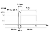
- FIG. 5 shows the transition of the change in the capacitance C accompanying the input operation for turning on the electrostatic switch 30 between the times tb and te.
- the threshold Th until the electrostatic switch 30 is turned on by an input operation is set to a reference threshold Tmin as a normal value.
- the reference threshold value Tmin is a low value that can detect an input operation of the finger F wearing a glove (see FIG. 6).
- the threshold value setting unit 53 acquires a capacitance peak value Cp (bf) from when the input operation ON time tb until a preset measurement time TP (for example, 200 milliseconds) elapses.
- TP for example, 200 milliseconds
- the threshold value setting unit 53 changes the threshold value Th from the reference threshold value Tmin to the adjustment threshold value Tar at the time tc when the measurement time TP has elapsed from the on time tb.
- the adjustment threshold value Tar is a value that is greater than or equal to the reference threshold value Tmin and that is less than the peak value Cp (bf).
- the threshold value setting unit 53 multiplies the peak value Cp (bf) by using a positive fraction less than 1 as a coefficient in order to set the adjustment threshold value Tar in a range lower than the peak value Cp (bf).
- the adjustment threshold value Tar is calculated.
- the threshold setting unit 53 continues to change the threshold Th to the adjustment threshold Tar from the off time te at which the electrostatic switch 30 switches from the on state to the off state until the time tr at which the predetermined time TA has elapsed.
- the predetermined time TA is set to about 5 seconds, for example.
- the threshold setting unit 53 returns the threshold Th from the adjustment threshold Tar to the reference threshold Tmin at time tr.
- the transition of the change in the capacitance C shown in FIG. 6 is associated with the input operation performed by the finger F with the glove attached.
- the electrostatic switch 30 is turned on at the on time tb by setting the reference threshold value Tmin assuming an input operation with the glove being worn.
- the peak value Cp (gf) acquired at the measurement time TP is lower than the peak value Cp (bf) at the time of the input operation with bare hands. Therefore, the adjustment threshold value Ton remains at a value slightly higher than the reference threshold value Tmin.
- the adjustment threshold value Tar is Are set to the same value as the reference threshold value Tmin.
- the transition of the change in the capacitance C shown in FIG. 7 is an input operation with a bare hand and is associated with an input operation performed in a time shorter than the measurement time TP.
- the threshold setting unit 53 calculates the adjustment threshold Tar by multiplying the peak value Cp (bf) measured between the on time tb and the off time te by a coefficient.
- the threshold setting unit 53 changes the threshold Th from the reference threshold Tmin to the adjustment threshold Tar at the off time te, not at the time tc (see FIG. 5) when the measurement time TP has elapsed from the time tb.
- the threshold setting unit 53 continues to change the threshold Th to the adjustment threshold Tar from time te to time tr when the predetermined time TA has elapsed.
- the threshold setting unit 53 adjusts the threshold Th for that purpose.
- the threshold setting unit 53 changes the threshold Th held for the specific electrostatic switch 30 from the reference threshold Tmin to the adjustment threshold Tar, and the threshold Th held for the non-specific electrostatic switch 30 is also changed from the reference threshold Tmin.
- the adjustment threshold value Tar is changed (see FIG. 5 and the like). The values of these adjustment threshold values Tar may differ depending on the function assigned to the specific electrostatic switch 30. Details thereof will be described below.
- the fan switches 301a and 301b, the temperature control switches 305a, 305b, 306a and 306b, and the mode change switch 302 can be subjected to continuous input operations, so-called “repetitive strikes”. Therefore, when any one of the switches 301a, 301b, 302, 305a, 305b, 306a, and 306b described above is the specific electrostatic switch 30, sensitivity adjustment for facilitating continuous hitting is performed.
- the threshold setting unit 53 associates two functionally related ones among the plurality of electrostatic switches 30 as related electrostatic switches.
- three sets of the fan switches 301a and 301b, the driver side temperature control switches 305a and 305b, and the passenger side temperature control switches 305a and 305b correspond to related electrostatic switches.
- the threshold setting unit 53 sets each adjustment threshold Ton of the two related electric switches to substantially the same value.
- the coefficient ai when calculating the adjustment threshold value Tar of the two related electrostatic switches is, for example, about 0.6.
- each adjustment threshold value Tar of other electrostatic switches (non-related electrostatic switches) excluding two related electrostatic switches is set to a value higher than each adjustment threshold value Tar of the related electric switch. Therefore, the coefficient aj when calculating the adjustment threshold value Tar of the unrelated electrostatic switch is set to about 0.8, for example.
- Each of the above coefficients is not limited to the above value as long as the relationship of 0 ⁇ ai ⁇ aj ⁇ 1 is satisfied, and may be changed as appropriate.
- the threshold setting unit 53 sets the adjustment threshold Ton of the mode changeover switch 302 to a value lower than the adjustment threshold Tar of other non-specific electrostatic switches 30. .
- a coefficient ai of about 0.6 is used.
- a coefficient aj of about 0.8 is used for calculating the adjustment threshold value Tar of the non-specific electrostatic switch 30.
- the threshold setting unit 53 substantially sets the same adjustment threshold Ton when each electrostatic switch 30 except the switches 301a, 301b, 302, 305a, 305b, 306a, and 306b is the specific electrostatic switch 30.
- the same coefficient ai (for example, about 0.8) is used to calculate each adjustment threshold value Taj.
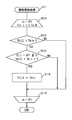
- each threshold Th [i] held for each electrostatic switch 30 [i] is initialized. Specifically, the reference threshold value Tmin is sequentially substituted for all the threshold values Th [i], and the process proceeds to S2.
- each electrostatic switch 30 is initialized to an off state. Specifically, the OFF value is sequentially substituted for all the state values S [i] indicating the on and off states of each electrostatic switch 30 [i], and the initialization process is terminated.
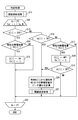
- the determination process shown in FIG. 9 is repeatedly started by the operation determination unit 52 after the initialization process (see FIG. 8).
- S11 of this determination process in order to set each threshold Th [i] of each electrostatic switch 30 [i] to the latest value, a threshold update process (see FIG. 10) described later is performed, and the process proceeds to S12.
- S12 the value to be substituted for [i] is determined, thereby selecting the electrostatic switch 30 [i] to be processed later, and the process proceeds to S13.
- the processes of S13 to S21 are performed for all the electrostatic switches 30 [i].
- S13 it is determined whether or not the state value S [i] of the electrostatic switch 30 [i] selected in S12 is OFF. If an affirmative determination is made in S13, the process proceeds to S14. In S14, it is determined whether or not the current capacitance C acquired from the capacitance measuring unit 51 is equal to or greater than the threshold Th [i]. If a negative determination is made in S14, the process proceeds to S22. On the other hand, in S15 when an affirmative determination is made in S14, the state value S [i] of the electrostatic switch 30 [i] is switched from OFF to ON. In addition, in S15, the present time t is substituted as the on time tb [i] when the electrostatic switch 30 is turned on, and the process proceeds to S22.
- the measurement time TP has just elapsed from the on time tb [i] depending on whether or not the difference between the current time t and the on time tb [i] is equal to the measurement time TP. It is determined whether or not. If an affirmative determination is made in S16 as the measurement time TP elapses from the on time tb [i], the process proceeds to S20. In S20, the peak value Cp of the capacitance from the on time tb [i] to the current time t when the measurement time TP has elapsed is calculated.
- S17 when a negative determination is made in S16, it is determined whether or not the current capacitance C is less than the threshold value Th [i]. If a negative determination is made in S17 due to the electrostatic switch 30 being kept pressed, the process proceeds to S22.
- the finger F is separated from the electrostatic switch 30, a positive determination is made in S17.
- S18 for determining the OFF state of electrostatic switch 30 is carried out.
- the state value S [i] of the electrostatic switch 30 [i] is switched from ON to OFF.
- the present time t is substituted as the off time te [i] when the electrostatic switch 30 [i] is turned off, and the process proceeds to S19.
- S19 it is determined whether or not the difference between the current time t and the on time tb [i], that is, the elapsed time from the on time tb [i] to the current time t is less than the measurement time TP. If the electrostatic switch 30 has been released within a measurement time TP by an input operation in a short time, an affirmative determination is made in S19. In S20 after an affirmative determination in S19, the peak value Cp of the capacitance due to the input operation less than the measurement time TP is calculated. On the other hand, if the electrostatic switch 30 has been pressed for the measurement time TP, a negative determination is made in S19. In this case, since the peak value Cp has been calculated by the determination process up to the previous time, the process proceeds to S22.
- the threshold value setting process (see FIG. 11) described later is performed by the threshold value setting unit 53, and the process proceeds to S22.
- the process returns to S12, and the target of processing is changed to the next electrostatic switch 30 [i + 1] by incrementing the value of [i] by one.
- This threshold value update process is a process for changing the threshold value Th [i], which has been changed from the reference threshold value Tmin to the adjustment threshold value Taj, to the reference threshold value Tmin again after a predetermined time TA has elapsed.
- S112 it is determined whether or not the threshold value Th [i] is larger than the reference threshold value Tmin. If a negative determination is made in S112, the process proceeds to S115. If it is determined in S112 that the threshold value Th [i] exceeds the reference threshold value Tmin, the process proceeds to S113.
- S113 it is determined whether or not the state value S [i] of the electrostatic switch 30 [i] is OFF and the predetermined time TA has elapsed from the OFF time te [i]. If it is determined in S113 that the predetermined time TA has not elapsed, the process proceeds to S115. On the other hand, if a positive determination is made in S113, the process proceeds to S114. In S114, the threshold setting unit 53 substitutes the reference threshold Tmin for the threshold Th [i] held in the operation determination unit 52, and the process proceeds to S115.
- the process returns to S111.
- S111 by increasing the value of [i] by 1, the processing target is changed to the next electrostatic switch 30 [i + 1].
- the threshold value update process is completed when the processes of S112 to S114 are completed for all the electrostatic switches 30. Thus, the process returns to the determination process shown in FIG. 9 and S12 (see FIG. 9) is performed.
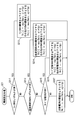
- the threshold setting process shown in FIG. 11 is performed by the operation determination unit 52 and the threshold setting unit 53.
- This threshold value setting process is a process for individually setting the value of each threshold value Th [i].
- Each coefficient used in the threshold determination process satisfies the relationship 0 ⁇ ai ⁇ aj ⁇ 1 as described above.
- S211 it is determined whether or not one of the state values S [i] of the fan switches 301a and 301b (see FIG. 2), which are related electrostatic switches, is turned on. If a negative determination is made in S211, the operation proceeds to S213. On the other hand, if an affirmative determination is made in S211, in S212, the threshold Th [i] for the fan switches 301a and 301b is selected from the value obtained by multiplying the peak value Cp by the coefficient ai and the reference threshold Tmin. Set the larger value with. Further, the threshold Th [i] of the other electrostatic switches 30 (unrelated electrostatic switches) excluding the fan switches 301a and 301b is obtained by multiplying the peak value Cp by the coefficient aj and the reference threshold Tmin. Set to the larger one.
- S213 it is determined whether or not one of the state values S [i] of the temperature adjustment switches 305a and 305b (see FIG. 2) on the driver's seat side is ON. If a negative determination is made in S213, the process proceeds to S215. On the other hand, if an affirmative determination is made in S213, in S214, the threshold Th [i] for the temperature adjustment switches 305a and 305b is calculated by multiplying the peak value Cp by the coefficient ai and the reference threshold Tmin. Set to the larger one. Further, each threshold Th [i] of the other electrostatic switches excluding the temperature adjustment switches 305a and 305b is set to a larger one of the value obtained by multiplying the peak value Cp by the coefficient aj and the reference threshold Tmin. Even when the passenger side temperature control switches 306a and 306b (see FIG. 2) are turned on, the processing corresponding to S213 and S214 is performed.
- S215 it is determined whether or not the state value S [i] of the mode switch 302 is turned on. If a negative determination is made in S215, the process proceeds to S217. On the other hand, if an affirmative determination is made in S215, the larger one of the threshold Th [i] of the mode changeover switch 302 in S216 is the value obtained by multiplying the peak value Cp by the coefficient ai and the reference threshold Tmin. Set to. Further, each threshold Th [i] of the other electrostatic switches excluding the mode changeover switch 302 is set to the larger one of the value obtained by multiplying the peak value Cp by the coefficient aj and the reference threshold Tmin.
- the threshold Th [i] of all the switches is set to the larger one of the value obtained by multiplying the peak value Cp by the coefficient aj and the reference threshold Tmin, and the threshold setting process is terminated. Thus, the process returns to the determination process shown in FIG. 9 and S22 is performed.
- the sensitivity of the electrostatic switch 30 before the input operation is increased by setting the reference threshold Tmin low. Therefore, even when a finger F wearing a glove performs an input operation as an operating body, the input operation can be detected by the electrostatic switch 30.
- the threshold Th is changed from the reference threshold Tmin to the adjustment threshold Taj. Therefore, the sensitivity of each electrostatic switch 30 is temporarily lowered during the predetermined time TA. Therefore, even when the finger F or the like not wearing gloves is the operating body, a situation in which the electrostatic switch 30 frequently causes false detections contrary to the operator's intention can be avoided.
- control panel 100 that can correctly detect the input operation corresponding to the state of the operation body is realized without separately providing a configuration for detecting the state of the operation body such as the finger F.
- the adjustment threshold value Ton is set in a range lower than the peak value Cp of the capacitance, it is determined whether there is an input operation based on the re-input operation performed within the predetermined time TA. Can be done.
- the control panel 100 avoids frequent erroneous detections and performs a reliable input operation within the predetermined time TA. It can be detected correctly.
- an adjustment threshold value Tar in a range lower than the peak value Cp is obtained.
- the adjustment threshold value Tar corresponding to the state of the operating tool can be set.
- the optimum adjustment threshold Tar is calculated according to the thickness of the glove, the strength of pressing the electrostatic switch 30, the conductivity of the surface of the finger F, and the like. Therefore, it is possible to reliably prevent the erroneous detection and to reliably detect the input operation within the predetermined time TA.
- the adjustment threshold value Tar falls below the reference threshold value Tmin, erroneous detection is likely to occur due to excessive sensitivity increase.
- the adjustment threshold value Tar is set to the same value as the reference threshold value Tmin. According to the above processing, frequent erroneous detection due to excessive sensitivity increase within the predetermined time TA can be prevented.
- the adjustment threshold Tar of the specific electrostatic switch 30 is a non-specific electrostatic switch. It is set lower than 30 adjustment threshold value Taj.
- the control panel 100 can correctly detect even when the electrostatic switch 30 is repeatedly input. It becomes possible.
- the adjustment threshold values Tar of all the electrostatic switches 30 are raised to the same value.
- the sensitivity of all the electrostatic switches 30 is temporarily lowered, so that the control panel 100 can quickly transition to a state in which it is difficult to cause erroneous detection.
- each adjustment threshold value Tar of these two related electrostatic switches is set to the value of the other unrelated electrostatic switch. It is set lower than the adjustment threshold value Tar. According to such sensitivity setting, even if an input operation is performed subsequent to the two related electrostatic switches, such a series of input operations can be correctly detected. In addition, a situation in which a series of input operations to the related electrostatic switch is erroneously detected by another electrostatic switch 30 can be prevented.
- the finger F corresponds to the “operation body” described in the claims
- the reference threshold Tmin corresponds to the “first threshold” described in the claims
- the adjustment threshold Tar is the patent. This corresponds to the “second threshold value” recited in the claims.
- the operation determination unit 52 corresponds to “determination means” described in the claims
- the threshold setting unit 53 corresponds to “threshold change means” described in the claims
- the control panel 100 claims Corresponds to “electronic device” described in the range.
- the coefficient ai corresponds to the “first coefficient” described in the claims
- the coefficient aj corresponds to the “second coefficient” described in the claims
- the air conditioner AC described in the claims. It corresponds to "equipment”.
- the adjacent electrostatic switch 30 adjacent to the specific electrostatic switch 30 is changed. Sensitivity is lowered.
- the inside / outside air changeover switch 303 shown in FIG. 2 is a specific electrostatic switch
- the auto air conditioner switch 304 and the mode changeover switch 302 correspond to adjacent electrostatic switches, and the sensitivity is lowered.
- the auto air conditioner switch 304 is likely to be close to the hand of an operator who performs an input operation to the inside / outside air changeover switch 303. Therefore, control for reducing the sensitivity of the auto air conditioner switch 304 is particularly effective for preventing erroneous detection.
- the adjustment threshold Ton of the adjacent electrostatic switch 30 is higher than the adjustment threshold Tar of the specific electrostatic switch 30.
- S217 of the threshold setting process shown in FIG. 11 is different from the above embodiment.
- the adjustment threshold value Tar of the specific electrostatic switch 30 in which an input operation has been performed is a value obtained by multiplying the peak value Cp of the capacitance by a predetermined coefficient ai (for example, about 0.6).
- the adjustment threshold value Tar of the adjacent electrostatic switch 30 is a value obtained by multiplying the coefficient aj by the peak value Cp.
- the threshold value Th of the other electrostatic switches 30 excluding the specific electrostatic switch 30 and the adjacent electrostatic switch 30 may not be changed to the adjustment threshold value Tar.
- a known technique can be appropriately applied as a method of calculating the peak value Cp of the capacitance in S21.
- the maximum value of the capacitance C within the measurement time TP may be simply set as the peak value Cp.
- the average value of the predetermined time before and behind including the maximum value of the electrostatic capacitance C may be made into the peak value Cp.
- the maximum value or an average value within a predetermined time including the maximum value may be set as the peak value Cp.
- the predetermined time TA which has been about 5 seconds, can be changed as appropriate.
- the predetermined time TA is preferably shorter than a time that does not cause a significant change in the state of the operating body, such as wearing gloves.
- the measurement time TP is not limited to 200 milliseconds, and can be appropriately changed within a range in which an input operation can be detected (for example, 40 to 200 milliseconds).
- the threshold value Th is changed from the reference threshold value Tmin to the adjustment threshold value Tar at the time tc when the measurement time TP has elapsed from the on time tb or the off time te.
- the timing at which the threshold Th is changed can be changed as appropriate.
- the adjustment threshold Tar is set in a range lower than the peak value Cp of the capacitance.
- the adjustment threshold Tar may be a value higher than the peak value Cp in order to reliably prevent erroneous detection.
- the adjustment threshold value Tar is set by the product of the peak value Cp and the coefficients ai, aj.
- the adjustment threshold value Tar is a preset fixed value that does not use the measured peak value Cp. Also good. Also in the form of using a coefficient for calculating the adjustment threshold value Taj, the value of this coefficient can be changed as appropriate.
- the functions provided by the elements 51 to 53 provided in the control circuit 50 can be provided by hardware and software different from those described above, or a combination thereof.
- the example in which the present disclosure is applied to the control panel 100 that operates the air conditioner AC mounted on the vehicle has been described.
- the sensitivity of each electrostatic switch is temporarily lowered when the finger F is separated from the specific electrostatic switch. Therefore, even if the finger F trying to move away from a specific electrostatic switch lightly touches an unintended electrostatic switch due to the vertical movement of the vehicle due to road irregularities, the false detection of the electrostatic switch with such unintended light contact Can be prevented.
- the present disclosure is not limited to the control panel 100 of the air conditioner AC, and can be applied to an operation device that operates a vehicle-mounted device or the vehicle-mounted device itself. Furthermore, the present disclosure is applicable not only to vehicles but also to all electronic devices including touch switches that detect an input operation based on a change in capacitance generated between an electrode and a finger.
Landscapes
- Input From Keyboards Or The Like (AREA)
- Position Input By Displaying (AREA)
- Switches That Are Operated By Magnetic Or Electric Fields (AREA)
Abstract
電子機器は、静電スイッチ(30)と、判定手段(52)と、閾値変更手段(53)と、を備える。静電スイッチは、操作体(F)による入力操作に伴った静電容量の変化を検出する。判定手段は、静電スイッチによって検出された静電容量(C)が閾値(Th)を超えたことに基づいて、操作体による入力操作の有り判定を行う。閾値変更手段は、判定手段によって入力操作が有ると判定された後の所定時間(TA)において、判定手段にて用いられる閾値を、通常値としての第一閾値(Tmin)から第一閾値以上の値である第二閾値(Taj)に変更する。
Description
本開示は、2013年11月28日に出願された日本出願番号2013-246236号に基づくもので、ここにその記載内容を援用する。
本開示は、静電スイッチを備える電子機器に関する。
近年、例えば特許文献1に開示のデジタルカメラのように、手指等の操作体による入力操作を静電容量の変化から検知する静電スイッチを備えた種々の電子機器が普及している。こうした静電スイッチは、入力操作に伴う静電容量の変化を検出する入力検出センサと、入力検出センサによって検出された静電容量に基づいて入力操作の有り判定を行う入力検出部を備えている。
しかし、上述したような静電スイッチは、一般に手袋を装着した状態の手指を検知することが困難である。そのため特許文献1に開示の構成は、手指に当たり易い位置に設けられた感度検出センサと、感度検出センサの検出結果に基づいて静電スイッチの感度を制御する制御部をさらに備えている。以上の構成により、手袋を装着した状態の手指による入力操作であっても、静電スイッチによる検知が可能にされている。
さて、特許文献1の感度検出センサは、電子機器を把持した手指と接触している必要があるため、把持状態にて使用されるデジタルカメラのような電子機器にしか適用できない。故に、本開示の発明者は、上述の感度検出センサのような構成を個別に設けることなく、操作体による入力操作を正しく検知可能な静電タッチスイッチの実現を試みた。
具体的には、入力操作の有り判定に用いられる閾値を、手袋を装着した状態の手指を検知できるよう低く設定することが考えられる。こうした閾値の設定によれば、静電スイッチの感度を高めることができるので、手袋を装着した手指による入力操作であっても、静電スイッチによる検知が可能になる。しかし、こうした閾値の設定では、手袋を装着していない状態の手指に対し静電スイッチが過敏に反応するため、操作者の意図に反した誤検知が頻発し得た。
こうした現象は、特に自動車の運転環境で顕著に発生する。詳記すると、操作者がコントロールパネル上にある静電スイッチを操作して手指を離そうとしたとき、車両が道路の凹凸で上下動したとする。すると手指は、操作対象としていた静電スイッチと近接する他の静電スイッチに、軽く触ることがある。こうした状況において、静電スイッチの感度が過敏だと、そのような意図しない軽い接触でも静電スイッチがオンしてしまい、誤検知となってしまう。
本開示は、操作体の状態を検出する構成を個別に設けることなく、操作体の状態に対応して、操作体による入力操作を正しく検知できる静電タッチスイッチを提供する。
本開示のある態様にかかる電子装置は、操作体による入力操作に伴った静電容量の変化を検出する静電スイッチと、静電スイッチによって検出された静電容量が閾値を超えたことに基づいて、操作体による入力操作の有り判定を行う判定手段と、判定手段によって入力操作が有ると判定された後の所定時間において、判定手段にて用いられる閾値を、通常値としての第一閾値から当該第一閾値以上の値である第二閾値に変更する閾値変更手段と、を備える。
この態様では、通常値として判定に用いられる第一閾値を低く設定することにより、入力操作の実施前における静電スイッチの感度が高くなる。故に、手袋を装着した状態の手指が操作体として入力操作を行った場合でも、この操作体による入力操作は、静電スイッチによって検知可能となる。
加えて、入力操作が有ると判定された後の所定時間では、判定手段にて用いられる閾値は、通常値である第一閾値から、第一閾値以上の第二閾値へと変更される。そのため、入力操作が実施された後の所定時間においては、静電スイッチの感度が一時的に低くされる。故に、手袋を未装着の手指等が操作体であった場合でも、操作者の意図に反した誤検知を静電スイッチが頻発させる事態は、回避され得る。
以上によれば、操作体の状態を検出する構成を個別に設けることなく、操作体の状態に対応して、操作体による入力操作を正しく検知できる電子機器が実現される。
本開示についての上記目的およびその他の目的、特徴や利点は、添付の図面を参照しながら下記の詳細な記述により、より明確になる。その図面は、
本開示の一実施形態によるコントロールパネルの車両に搭載された状態を示す図である。
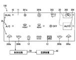
コントロールパネルの正面図である。
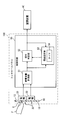
コントロールパネルの電気的な構成を示すブロック図である。
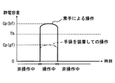
手袋の有無によって変化する静電容量のピーク値と、判定に用いられる閾値との関係を示す図である。
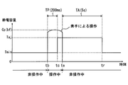
素手による入力操作によって生じる静電容量の変化と、それに伴う閾値の変化を時間の経過に沿って示す図である。
手袋を装着した状態での入力操作によって生じる静電容量の変化と、それに伴う閾値の変化を時間の経過に沿って示す図である。
計測時間よりも短い入力操作によって生じる静電容量の変化と、それに伴う閾値の変化を時間の経過に沿って示す図である。
制御回路において実施される初期化処理を示すフローチャートである。
制御回路において実施される判定処理を示すフローチャートである。
制御回路において実施される閾値更新処理を示すフローチャートである。
制御回路において実施される閾値設定処理を示すフローチャートである。
以下、本開示の一実施形態を図面に基づいて説明する。
図1,図2に示す本開示の一実施形態によるコントロールパネル100は、車両に搭載された空調装置ACを操作するための電子機器である。コントロールパネル100は、車室内のインスツルメントパネル90に設けられたセンタークラスタ90aに設置され、操作者の手指Fの届き易い範囲に複数の静電スイッチ30を露出させている。操作者は、静電スイッチ30への入力操作により、空調装置ACの動作モードの変更や設定値の調整等を行うことができる。空調装置ACの作動状態を示す情報は、センタークラスタ90aに設置されたディスプレイ91の表示によって操作者に通知される。
図2に示すように、複数の静電スイッチ30は、コントロールパネル100の左右方向及び上下方向に互いに間隔を開けて配列されている。コントロールパネル100の上段には、一組のファンスイッチ301a,301b、モード切替スイッチ302、及び内外気切替スイッチ303等が配置されている。コントロールパネル100の中段には、フロントデフロスタースイッチ及びリヤウインドゥデフォッガースイッチに加えて、オートエアコンスイッチ304等が配列されている。コントロールパネル100の下段には、二組の温度調節スイッチ305a,305b,306a,306b等が配列されている。
ファンスイッチ301a,301bには、空調装置ACの風量の設定値を調整する風量調整機能が割り当てられている。モード切替スイッチ302には、吹き出し口の動作モードを、例えばFACEモード→BiLevel→FOOTという順でサイクリックに切り替える切替機能が割り当てられている。内外気切替スイッチ303には、空調装置ACにおいて内気循環モードと外気導入モードとを切り替える切替機能が割り当てられている。
尚、吹き出し口のように、三つ以上の動作モードを循環させる切替機能を循環切替機能といい、内気循環モードと外気導入モードとの切り替えのように、二つの動作モードを変更させる切替機能を単純切替機能という。
オートエアコンスイッチ304には、オートエアコンのオン及びオフを切り替える単純切替機能が割り当てられている。温度調節スイッチ305a,305bには、空調装置ACにおける運転席側(図1参照)の温度設定値を調整する温度調整機能が割り当てられている。温度調節スイッチ306a,306bには、空調装置ACにおける助手席側(図1参照)の温度設定値を調整する温度調整機能が割り当てられている。
コントロールパネル100は、図2,3に示すように、スイッチパネル部材10、複数のスイッチ電極20、及び制御回路50等によって構成されている。
スイッチパネル部材10は、例えば板状に加工された透光性の樹脂材料を基材とし、この基材に遮光性塗料による塗装又は遮光性インクによる印刷を施すことにより形成されている。スイッチパネル部材10において操作者に向けて露出したおもて面には、複数の入力面11が形成されている。
入力面11は、静電スイッチ30の一部であり、静電スイッチ30のうちで手指Fと接触する部分である。各入力面11には、各静電スイッチ30に割り当てられた機能を抽象化したアイコン12が形成されている。アイコン12は、遮光性の塗装又は印刷に替えて施された透光性の塗装又は印刷によって形成されている。アイコン12は、スイッチパネル部材10の裏面13側に設けられた光源(図示しない)からの光を透過させることにより、発光表示される。
スイッチ電極20は、入力面11等と組み合わされることにより、静電スイッチ30を形成している。スイッチ電極20は、絶縁フィルムに塗布された導電性高分子塗料(例えばPEDOT)等によって膜状に形成されている。スイッチ電極20は、光源からの光をスイッチパネル部材10に向けて透過可能なよう、透光性を有している。各スイッチ電極20は、スイッチパネル部材10において入力面11の反対側に位置する裏面13に、各アイコン12と重畳するように、両面テープ又は接着剤等によって取り付けられおり、制御回路50と電気的に接続されている。スイッチ電極20は、入力面11に触れた手指Fとの間にて静電容量Cを生じさせる。手指F及びスイッチ電極20間に生じる静電容量Cは、入力面11から手指Fまでの距離に応じて変化する。尚、スイッチ電極20の形成材料としては、上述の材料に替えて、例えば酸化インジウムスズ、多数の透光孔を開口させた金属の膜材、カーボン等の導電性物質を含む印刷材料等が採用可能である。
制御回路50は、静電容量計測部51、操作判定部52、及び閾値設定部53等によって構成されている。これら要素51~53は、専用の集積回路の組み合わせによって構成されていてもよく、又は所定のプログラムを実行するマイクロコンピュータの機能ブロックであってもよい。制御回路50は、スイッチパネル部材10の裏面13側に配置された回路基板(図示しない)に形成されている。
静電容量計測部51は、各静電スイッチ30にて検出される静電容量Cの変化を取得する。具体的に静電容量計測部51は、各スイッチ電極20から出力される信号(例えば電位)を取得し、各静電スイッチ30において生じている静電容量Cを個別に計測する。静電容量計測部51は、静電スイッチ30によって検出された静電容量Cの値を、操作判定部52及び閾値設定部53に出力する。
操作判定部52は、静電スイッチ30にて検出された静電容量Cの計測値(図4参照)を静電容量計測部51から取得し、取得した静電容量Cと予め設定された閾値Th(図4参照)とを比較する。操作判定部52は、複数の静電スイッチ30のそれぞれに対し、入力操作の有り判定を行うための閾値Thを個別に保持している。操作判定部52は、閾値設定部53からの出力に基づいて、各閾値Thを再設定することができる。操作判定部52は、静電容量Cが閾値Thを超えたことに基づいて、手指Fによる入力操作の有り判定を行う。以下の説明では、静電容量Cが閾値Thを超えた状態を静電スイッチ30のオン状態といい、静電容量Cが閾値Th以下の状態を静電スイッチ30のオフ状態という。操作判定部52は、各静電スイッチ30のオン及びオフの状態を示す判定結果を、制御回路50の外部に出力することにより、空調装置ACの制御部に取得させる。加えて操作判定部52は、上述の判定結果を閾値設定部53に出力する。
閾値設定部53は、タイマ54を有している。タイマ54は、閾値Thを一時的に変更する処理(後述する)の適用時間の計測に用いられる構成である。タイマ54によって計測された時刻は、操作判定部52にも出力される。閾値設定部53は、静電スイッチ30にて検出される静電容量Cの計測値を静電容量計測部51から取得する。閾値設定部53は、各静電スイッチ30のオン及びオフの状態を示す判定結果を、操作判定部52から取得する。
ここで、静電スイッチ30にて検出される静電容量Cは、手指F等の操作体の状態により、顕著に変動する。例えば操作者が素手によって入力操作を行った場合では、図4に示す如く、計測される静電容量のピーク値Cp(bf)は、通常の閾値Thを確実に超える値となる。一方で、手袋を装着した状態で入力操作を行った場合では、計測される静電容量のピーク値Cp(gf)は、閾値Thを大きく下回るようになる。これは、手指F及びスイッチ電極20間の距離が手袋の介在によって拡大した結果、手指F及びスイッチ電極20間の電荷が減少することに起因している。
図3に示す閾値設定部53は、上述したような操作体の状態に適宜対応し、操作判定部52に保持された閾値Thを再設定する機能を有する。加えて操作判定部52は、閾値Thの調整により、各静電スイッチ30への入力操作の操作性を向上させることがでる。こうした効果獲得のため、閾値設定部53は、入力操作のあった静電スイッチ30にて検出される静電容量Cから、現在操作中の手指Fを検知するために最適な閾値Thを求める。そして閾値設定部53は、算出した閾値Thを操作判定部52に出力し、入力操作が有ると判定された後において操作判定部52に保持された閾値Thを一時的に変更させる。こうした閾値Thを変更させる閾値設定部53の作動の詳細を、以下図5~図7に基づいて説明する。
図5には、時刻tb~te間にて静電スイッチ30をオン状態にする入力操作に伴った静電容量Cの変化の推移が示されている。入力操作によって静電スイッチ30がオン状態となるまでの閾値Thは、通常値としての基準閾値Tminに設定されている。基準閾値Tminは、手袋を装着した手指Fの入力操作を検知可能な低い値とされている(図6参照)。閾値設定部53は、入力操作のオン時刻tbから予め設定された計測時間TP(例えば、200ミリ秒)が経過するまでの間の静電容量のピーク値Cp(bf)を取得する。
閾値設定部53は、オン時刻tbから計測時間TPが経過した時刻tcにて、閾値Thを基準閾値Tminから調整閾値Tajに変更する。調整閾値Tajは、基準閾値Tmin以上の値であり、且つ、ピーク値Cp(bf)未満の値である。閾値設定部53は、調整閾値Tajをピーク値Cp(bf)よりも低い範囲で設定するために、予め規定された1未満の正の小数を係数としてピーク値Cp(bf)に乗算することにより、調整閾値Tajを算出する。
閾値設定部53は、静電スイッチ30がオン状態からオフ状態へと切り替わるオフ時刻teから、所定時間TAの経過する時刻trまで、調整閾値Tajへの閾値Thの変更を継続する。所定時間TAは、例えば5秒程度に設定されている。閾値設定部53は、時刻trにて、閾値Thを調整閾値Tajから基準閾値Tminに戻す。
図6に示される静電容量Cの変化の推移は、手袋を装着した状態の手指Fによってなされた入力操作に伴うものである。手袋を装着した状態での入力操作を想定した基準閾値Tminの設定により、静電スイッチ30は、オン時刻tbにてオン状態となる。この入力操作では、計測時間TPにて取得されるピーク値Cp(gf)が素手による入力操作時のピーク値Cp(bf)よりも低い値となる。故に、調整閾値Tajは、基準閾値Tminよりも僅かに高い値に留まる。尚、後述の閾値設定処理(図11参照)の説明にて詳記するように、静電容量のピーク値(gf)と係数との積が基準閾値Tminよりも小さくなる場合、調整閾値Tajは、基準閾値Tminと同じ値に設定される。
図7に示される静電容量Cの変化の推移は、素手による入力操作であって、計測時間TPよりも短い時間で行われた入力操作に伴うものである。こうした短時間での入力操作でも、閾値設定部53は、オン時刻tbからオフ時刻teまでの間に計測されたピーク値Cp(bf)に係数を乗算して、調整閾値Tajを算出する。閾値設定部53は、時刻tbから計測時間TPが経過した時刻tc(図5参照)ではなく、オフ時刻teにて閾値Thを基準閾値Tminから調整閾値Tajに変更する。そして、閾値設定部53は、時刻teから所定時間TAの経過した時刻trまで、調整閾値Tajへの閾値Thの変更を継続する。
コントロールパネル100では、図2,図3に示す複数の静電スイッチ30の一つに入力操作が加えられると、この静電スイッチ(特定静電スイッチ)30の感度だけでなく、他の静電スイッチ(非特定静電スイッチ)30の感度も、連動して調整される。そのための閾値Thの調整を、閾値設定部53は実施する。閾値設定部53は、特定静電スイッチ30に対し保持される閾値Thを基準閾値Tminから調整閾値Tajに変更し、且つ、非特定静電スイッチ30に対し保持される閾値Thも基準閾値Tminから調整閾値Tajに変更する(図5等参照)。これらの調整閾値Tajの値は、特定静電スイッチ30に割り当てられた機能の違いによって異なる場合がある。その詳細を、以下説明する。
複数の静電スイッチ30のうちで、ファンスイッチ301a,301b、温度調節スイッチ305a,305b,306a,306b、及びモード切替スイッチ302には、連続した入力操作、所謂「連打」が行われ得る。そのため、上記したスイッチ301a,301b,302,305a,305b,306a,306bのいずれかが特定静電スイッチ30である場合、連打の入力を容易にするための感度調整が実施される。
具体的に閾値設定部53は、複数の静電スイッチ30のうちで、機能的に関連した二つを関連静電スイッチとして関連付けている。本実施形態では、ファンスイッチ301a,301b、運転席側の温度調節スイッチ305a,305b、並びに助手席側の温度調節スイッチ305a,305bの三組が、関連静電スイッチに該当する。
閾値設定部53は、二つの関連静電スイッチの一方が特定静電スイッチ30である場合に、二つの関連性電スイッチの各調整閾値Tajを、実質同一の値に設定する。二つの関連静電スイッチの調整閾値Tajを算出する際の係数aiは、例えば0.6程度とされる。一方で、二つの関連静電スイッチを除く他の静電スイッチ(非関連静電スイッチ)の各調整閾値Tajは、関連性電スイッチの各調整閾値Tajよりも高い値に設定される。そのため、非関連静電スイッチの調整閾値Tajを算出する際の係数ajは、例えば0.8程度とされる。以上の各係数は、0<ai<aj<1の関係を満たしていれば、上述の値に限定されず、適宜変更されてよい。
さらに閾値設定部53は、モード切替スイッチ302が特定静電スイッチ30である場合、モード切替スイッチ302の調整閾値Tajを、他の非特定静電スイッチ30の調整閾値Tajよりも低い値に設定する。モード切替スイッチ302の調整閾値Tajの算出には、0.6程度の係数aiが用いられる。一方で、非特定静電スイッチ30の調整閾値Tajの算出には、0.8程度の係数ajが用いられる。
そして閾値設定部53は、上記のスイッチ301a,301b,302,305a,305b,306a,306bを除く各静電スイッチ30が特定静電スイッチ30である場合には、全ての調整閾値Tajを実質同一の値に設定する。この場合、全ての静電スイッチ30の感度を低下させるため、各調整閾値Tajの算出には、同一の係数ai(例えば0.8程度)が用いられる。
ここまで説明したコントロールパネル100の作動を実現するために、制御回路50において実施される各処理を、図8~図11に基づき、図3を参照しつつ説明する。以下の各処理は、車両のアクセサリ(ACC)電源がオン状態とされる、又は車両のイグニッションがオン状態とされることによって開始される。以下の説明に用いられる[i]は、静電スイッチ30の識別のために割り振られた識別番号であり、1~N(Nは静電スイッチの個数)までの整数が代入される。
図8に示す初期化処理は、コントロールパネル100への電力供給の開始に基づいて、操作判定部52及び閾値設定部53の協働により実施される。この初期化処理のS1では、各静電スイッチ30[i]に対して保持される各閾値Th[i]を初期化する。具体的には、全ての閾値Th[i]に対して順に基準閾値Tminを代入し、S2に進む。S2では、各静電スイッチ30の状態をオフ状態に初期化する。具体的には、各静電スイッチ30[i]のオン及びオフ状態を示す状態値S[i]の全てに対して順にOFFの値を代入し、初期化処理を終了する。
図9に示す判定処理は、初期化処理後(図8参照)に操作判定部52によって繰り返し開始される。この判定処理のS11では、各静電スイッチ30[i]の各閾値Th[i]を最新の値に設定するため、後述する閾値更新処理(図10参照)を実施し、S12に進む。S12では、[i]に代入する値を決定することで、以降の処理の対象となる静電スイッチ30[i]を選択し、S13に進む。S12及びS22の処理により、S13~S21の処理が全ての静電スイッチ30[i]に対して行われる。
S13では、S12にて選択された静電スイッチ30[i]の状態値S[i]がOFFであるか否かを判定する。S13にて、肯定判定をした場合には、S14に進む。S14では、静電容量計測部51から取得する現在の静電容量Cが、閾値Th[i]以上か否かを判定する。S14にて否定判定をした場合には、S22に進む。一方、S14にて肯定判定をした場合のS15では、静電スイッチ30[i]の状態値S[i]をOFFからONへと切り替える。加えてS15では、静電スイッチ30がオン状態となったオン時刻tb[i]として、現在の時刻tを代入し、S22に進む。
S13にて否定判定をした場合のS16では、現在の時刻tとオン時刻tb[i]との差分が計測時間TP等しいか否かにより、オン時刻tb[i]から計測時間TPがちょうど経過したか否かを判定する。S16にて、オン時刻tb[i]からの計測時間TPの経過によって肯定判定をした場合には、S20に進む。このS20では、オン時刻tb[i]から計測時間TPの経過した現在時刻tまでの間における静電容量のピーク値Cpを計算する。
一方、S16にて否定判定をした場合のS17では、現在の静電容量Cが、閾値Th[i]未満か否かを判定する。静電スイッチ30が押し続けられていることに起因して、S17にて否定判定をした場合には、S22に進む。対して、静電スイッチ30から手指Fが離れた場合には、S17にて肯定判定を行う。そして、静電スイッチ30のオフ状態を確定させるためのS18を実施する。S18では、静電スイッチ30[i]の状態値S[i]をONからOFFへと切り替える。加えてS18では、静電スイッチ30[i]がオフ状態となったオフ時刻te[i]として、現在の時刻tを代入し、S19に進む。
S19では、現在の時刻tとオン時刻tb[i]との差分、即ちオン時刻tb[i]から現在の時刻tまでの経過時間が、計測時間TP未満か否かを判定する。短時間での入力操作により静電スイッチ30を計測時間TP未満で離していた場合には、S19において肯定判定を行う。そして、S19の肯定判定後のS20では、計測時間TP未満の入力操作による静電容量のピーク値Cpが計算される。一方、計測時間TPを超えて静電スイッチ30を押し続けていた場合には、S19において否定判定を行う。この場合、前回までの判定処理によりピーク値Cpが計算済みであるため、S22に進む。
S20の後のS21では、後述する閾値設定処理(図11参照)を閾値設定部53に実施させ、S22に進む。S22では、処理をS12に戻し、[i]の値を1つ増やすことにより、処理の対象を次の静電スイッチ30[i+1]へと変更する。全ての静電スイッチ30に対しS13~S21の処理を行うと、判定処理を終了させる。
図10に示す閾値更新処理は、操作判定部52及び閾値設定部53によって実施される。この閾値更新処理は、基準閾値Tminから調整閾値Tajへと変更された閾値Th[i]を、所定時間TAの経過後に再び基準閾値Tminに変更するための処理である。
S111では、[i]に代入する値を決定することで、以降の処理の対象となる静電スイッチ30[i]を選択し、S112に進む。S112及びS115の処理により、S112~S114の処理が全ての静電スイッチ30[i]に対して行われる。
S112では、閾値Th[i]が基準閾値Tminよりも大きいか否かを判定する。S112にて否定判定をした場合には、S115に進む。S112にて、閾値Th[i]が基準閾値Tminを超えている旨の肯定判定をした場合には、S113に進む。
S113では、静電スイッチ30[i]の状態値S[i]がOFFであり、且つ、オフ時刻te[i]から所定時間TAが経過したか否かを判定する。S113にて、所定時間TAが経過していない旨の否定判定をした場合には、S115に進む。一方、S113にて肯定判定をした場合には、S114に進む。S114では、閾値設定部53が操作判定部52に保持される閾値Th[i]に基準閾値Tminを代入し、S115に進む。
S115では、処理をS111に戻す。S111では、[i]の値を1つ増やすことで、処理の対象が次の静電スイッチ30[i+1]へと変更する。全ての静電スイッチ30に対しS112~S114の処理の完了により、閾値更新処理を終了する。以上により、図9に示す判定処理に戻り、S12(図9参照)を実施する。
図11に示す閾値設定処理は、操作判定部52及び閾値設定部53によって実施される。この閾値設定処理は、各閾値Th[i]の値を個別に設定する処理である。閾値判定処理にて用いられる各係数は、上述のように0<ai<aj<1の関係を満たしている。
S211では、関連静電スイッチであるファンスイッチ301a,301b(図2参照)のいずれかの状態値S[i]がONとなったか否かを判定する。S211にて、否定判定をした場合にはS213に進む。一方、S211にて肯定判定をした場合には、S212にて、ファンスイッチ301a,301bについての各閾値Th[i]を、ピーク値Cpに係数aiを乗算した値と、基準閾値Tminとのうちで大きい方に設定する。さらに、ファンスイッチ301a,301bを除く他の静電スイッチ30(非関連静電スイッチ)の各閾値Th[i]を、ピーク値Cpに係数ajを乗算した値と、基準閾値Tminとのうちで大きい方に設定する。
S213では、運転席側の温度調節スイッチ305a,305b(図2参照)のいずれかの状態値S[i]がONとなったか否かを判定する。S213にて、否定判定をした場合にはS215に進む。一方、S213にて肯定判定をした場合には、S214にて、温度調節スイッチ305a,305bについての各閾値Th[i]を、ピーク値Cpに係数aiを乗算した値と、基準閾値Tminとのうちで大きい方に設定する。さらに、温度調節スイッチ305a,305bを除く他の静電スイッチの各閾値Th[i]を、ピーク値Cpに係数ajを乗算した値と、基準閾値Tminとのうちで大きい方に設定する。尚、助手席側の温度調節スイッチ306a,306b(図2参照)がオン状態となった場合にも、S213及びS214に相当する処理が実施される。
S215では、モード切替スイッチ302の状態値S[i]がONとなったか否かを判定する。S215にて、否定判定をした場合には、S217に進む。一方、S215にて肯定判定をした場合には、S216にて、モード切替スイッチ302の閾値Th[i]を、ピーク値Cpに係数aiを乗算した値と、基準閾値Tminとのうちで大きい方に設定する。さらに、モード切替スイッチ302を除く他の静電スイッチの各閾値Th[i]を、ピーク値Cpに係数ajを乗算した値と、基準閾値Tminとのうちで大きい方に設定する。
S217では、全てのスイッチの閾値Th[i]をピーク値Cpに係数ajを乗算した値と、基準閾値Tminとのうちで大きい方に設定し、閾値設定処理を終了する。以上により、図9に示す判定処理に戻り、S22を実施する。
ここまで説明した本実施形態では、基準閾値Tminを低く設定することにより、入力操作前における静電スイッチ30の感度が高められている。故に、手袋を装着した状態の手指Fが操作体として入力操作を行った場合でも、この入力操作は、静電スイッチ30によって検知可能となる。
加えて、入力操作が有ると判定された後の所定時間TAにおいて、閾値Thは、基準閾値Tminから調整閾値Tajへと変更される。そのため、所定時間TAにおいては、各静電スイッチ30の感度が一時的に低くされる。故に、手袋を未装着の手指F等が操作体であった場合でも、操作者の意図に反した誤検知を静電スイッチ30が頻発させる事態は、回避され得る。
以上によれば、手指F等の操作体の状態を検出する構成を個別に設けることなく、操作体の状態に対応して、入力操作を正しく検知できるコントロールパネル100が実現される。
加えて本実施形態によれば、調整閾値Tajが静電容量のピーク値Cpよりも低い範囲で設定されるので、所定時間TA内に行われる再度の入力操作に基づいて、入力操作の有り判定が行われ得る。このように、静電容量のピーク値Cpよりも調整閾値Tajを低く設定する制御によれば、コントロールパネル100は、誤検知の頻発を回避したうえで、所定時間TA内における確実な入力操作を正しく検知できるようになる。
また本実施形態のように、静電容量のピーク値Cpに1未満の正の小数を係数として乗算すれば、ピーク値Cpよりも低い範囲の調整閾値Tajが得られる。こうした処理によれば、操作体の状態に対応した調整閾値Tajが設定可能となる。具体的には、手袋の厚み、静電スイッチ30を押す力の強弱、及び手指F表面の導電率等に応じて、最適な調整閾値Tajが算出される。したがって、誤検知の回避を可能にし、且つ、所定時間TA内における入力操作を正しく検知可能にする効果が、確実に発揮される。
ここで、計測されたピーク値Cpが低いと、ピーク値Cpと係数との積は、基準閾値Tminよりも小さい値となり得る。このように、調整閾値Tajが基準閾値Tminを下回ってしまうと、過度な感度上昇によって誤検知が生じ易くなる。こうした事態を回避するため、本実施形態では、ピーク値Cpと係数との積が基準閾値Tminよりも小さい場合に、調整閾値Tajは、基準閾値Tminと同じ値に設定される。以上の処理によれば、所定時間TA内での過度な感度上昇に起因した誤検知の頻発は、防がれ得る。
さらに本実施形態のように、複数の静電スイッチ30が並列されたコントロールパネル100では、特定の静電スイッチ30への入力操作を行う過程で、他の静電スイッチ30に誤って検知される虞がある。そこで、特定の静電スイッチ30に入力操作があった場合に、所定時間TA、この特定静電スイッチ30の閾値Thだけでなく、他の非特定静電スイッチ30の閾値Thも、基準閾値Tminから調整閾値Tajへと変更される。こうした制御が実施されることにより、所望の特定静電スイッチ30への入力操作を終えた後に、移動中の手等を他の静電スイッチ30が誤検知してしまう事態は、回避可能となる。
また加えて本実施形態では、連打の入力が想定される一部の静電スイッチ30が特定静電スイッチ30であった場合、この特定静電スイッチ30の調整閾値Tajは、非特定静電スイッチ30の調整閾値Tajよりも低く設定される。このように、特定静電スイッチ30の感度が他の非特定静電スイッチ30の感度よりも高められることによれば、静電スイッチ30を連打するような入力でも、コントロールパネル100は、正しく検知可能となる。加えて、連打の入力が他の静電スイッチ30によって誤検知される事態も、回避可能となる。
さらに加えて本実施形態によれば、連打される虞の低い静電スイッチ30が特定静電スイッチ30であった場合、全ての静電スイッチ30の各調整閾値Tajは、同じ値まで引き上げられる。こうして全ての静電スイッチ30の感度が一時的に下げられることにより、コントロールパネル100は、誤検知を生じさせ難い状態へと速やかに遷移し得る。
またさらに本実施形態では、機能的に関連した二つの関連静電スイッチの一方に入力があった場合に、これら二つの関連静電スイッチの各調整閾値Tajが、他の非関連静電スイッチの調整閾値Tajよりも低くされる。こうした感度設定によれば、二つの関連静電スイッチに続けて入力操作が行われても、こうした一連の入力操作は、正しく検知されるようになる。加えて、関連静電スイッチへの一連の入力操作が他の静電スイッチ30によって誤検知される事態も、防がれ得る。
尚、本実施形態では、手指Fが特許請求の範囲に記載の「操作体」に相当し、基準閾値Tminが特許請求の範囲に記載の「第一閾値」に相当し、調整閾値Tajが特許請求の範囲に記載の「第二閾値」に相当する。また、操作判定部52が特許請求の範囲に記載の「判定手段」に相当し、閾値設定部53が特許請求の範囲に記載の「閾値変更手段」に相当し、コントロールパネル100が特許請求の範囲に記載の「電子機器」に相当する。さらに、係数aiが特許請求の範囲に記載の「第一係数」に相当し、係数ajが特許請求の範囲に記載の「第二係数」に相当し、空調装置ACが特許請求の範囲に記載の「機器」に相当する。
(変形例)
以上、本開示による一実施形態について説明したが、本開示は、上記実施形態に限定して解釈されるものではなく、本開示の要旨を逸脱しない範囲内において種々の実施形態及び組み合わせに適用することができる。
以上、本開示による一実施形態について説明したが、本開示は、上記実施形態に限定して解釈されるものではなく、本開示の要旨を逸脱しない範囲内において種々の実施形態及び組み合わせに適用することができる。
上記実施形態の変形例1では、複数の静電スイッチ30の一つである特定静電スイッチ30に入力操作が加えられた場合に、当該特定静電スイッチ30に隣接する隣接静電スイッチ30の感度が下げられる。具体例としては、図2に示す内外気切替スイッチ303が特定静電スイッチである場合、オートエアコンスイッチ304及びモード切替スイッチ302が、隣接静電スイッチに該当し、感度を下げられる。こうした制御により、内外気切替スイッチ303への入力操作がオートエアコンスイッチ304及びモード切替スイッチ302によって誤検知される事態は、確実に回避可能となる。特に、オートエアコンスイッチ304は、内外気切替スイッチ303へ入力操作を行う操作者の手に近接し易い。故に、オートエアコンスイッチ304の感度を下げる制御は、誤検知防止に特に有効である。
以上の感度調整を実現するため、変形例1では、特定静電スイッチ30の調整閾値Tajよりも、隣接静電スイッチ30の調整閾値Tajが高い値とされる。具体的には、図11に示す閾値設定処理のS217が上記実施形態とは異なる。変形例1では、入力操作のあった特定静電スイッチ30の調整閾値Tajは、静電容量のピーク値Cpに予め規定された係数ai(例えば0.6程度)を乗算した値とされる。一方、隣接静電スイッチ30の調整閾値Tajは、係数ajにピーク値Cpを乗算した値とされる。これらの各係数は、上述のように0<ai<aj<1の関係を満たしている。尚、変形例1では、特定静電スイッチ30及び隣接静電スイッチ30を除く他の静電スイッチ30の閾値Thは、調整閾値Tajに変更されてなくてもよい。
上記実施形態において、S21の静電容量のピーク値Cpを算出する手法は、公知の技術を適宜適用可能である。例えば、単純に計測時間TP内での静電容量Cの最大値が、ピーク値Cpとされよい。又は、静電容量Cの最大値を含む前後の所定時間の平均値が、ピーク値Cpとされよい。さらに、静電容量Cの信号から高周波(ノイズ)成分を除去したうえで、最大値又は最大値を含む所定時間内の平均値がピーク値Cpとされてもよい。
上記実施形態にて、5秒程度とされていた所定時間TAは、適宜変更可能である。この所定時間TAは、例えば手袋を装着する等、操作体の状態に顕著な変化が生じない程度の時間よりも短くされることが望ましい。加えて所定時間TAは、操作者が所望の静電スイッチを押圧する一連の操作の継続時間よりも長くされることが望ましい。また、計測時間TPも、200ミリ秒に限定されず、入力操作を検知可能な範囲(例えば40~200ミリ秒)内で適宜変更可能である。
上記実施形態では、オン時刻tbから計測時間TPが経過した時刻tc又はオフ時刻teにおいて、閾値Thは、基準閾値Tminから調整閾値Tajへと変更されていた。しかし、操作判定部52によって入力操作が有ると判定された後、即ちオン時刻tb以降であれば、閾値Thの変更されるタイミングは、適宜変更可能である。
上記実施形態において、調整閾値Tajは、静電容量のピーク値Cpよりも低い範囲で設定されていた。しかし、確実な誤検知防止のために、調整閾値Tajは、ピーク値Cpより高い値であってもよい。また、上記実施形態では、ピーク値Cpと係数ai,ajの積によって調整閾値Tajを設定していたが、調整閾値Tajは、計測したピーク値Cpを用いない予め設定された固定値であってもよい。また、調整閾値Tajの算出に係数を用いる形態においても、この係数の値は適宜変更可能である。
上記実施形態において、制御回路50に設けられた各要素51~53によって提供されていた機能は、上述のものとは異なるハードウェア及びソフトウェア、或いはこれらの組み合わせによっても提供可能である。
上記実施形態では、車両に搭載された空調装置ACを操作するコントロールパネル100に、本開示を適用した例を説明した。本開示を適用したコントロールパネル100であれば、特定の静電スイッチから手指Fを離そうとしたときに、各静電スイッチの感度が一時的に引き下げられている。故に、特定の静電スイッチから離そうとした手指Fが、道路の凹凸による車両の上下動によって意図しない静電スイッチに軽く触れたとしても、こうした意図しない軽い接触での静電スイッチの誤検知は、防がれ得る。
しかし、本開示は、こうした空調装置ACのコントロールパネル100に限らず、車載された機器を操作する操作装置又は車載機器自体に適用可能である。さらに、車両用に限らず、電極と手指等との間に生じる静電容量の変化に基づいて入力操作が検知されるタッチスイッチを備えた電子機器全般に、本開示は適用可能である。
Claims (14)
- 操作体(F)による入力操作に伴った静電容量の変化を検出する静電スイッチ(30)と、
前記静電スイッチによって検出された静電容量(C)が閾値(Th)を超えたことに基づいて、前記操作体による入力操作の有り判定を行う判定手段(52)と、
前記判定手段によって入力操作が有ると判定された後の所定時間(TA)において、前記判定手段にて用いられる前記閾値を、通常値としての第一閾値(Tmin)から当該第一閾値以上の値である第二閾値(Taj)に変更する閾値変更手段(53)と、を備える電子機器。 - 前記閾値変更手段は、前記静電スイッチによって検出された静電容量のピーク値(Cp)よりも低い範囲で前記第二閾値を設定する請求項1に記載の電子機器。
- 前記閾値変更手段は、予め規定された係数を前記ピーク値に乗算した値を前記第二閾値として設定する請求項2に記載の電子機器。
- 前記閾値変更手段は、前記係数と前記ピーク値との積が前記第一閾値よりも小さい場合、前記第二閾値を前記第一閾値と同じ値に設定する請求項3に記載の電子機器。
- 並列された複数の前記静電スイッチを備える電子機器であって、
前記判定手段は、複数の前記静電スイッチのそれぞれに対し、入力操作の有り判定を行うための前記閾値を個別に保持する請求項1~4のいずれか一項に記載の電子機器。 - 前記閾値変更手段は、複数の前記静電スイッチの一つである特定静電スイッチに入力操作が有ると判定された場合に、前記所定時間において、当該特定静電スイッチに対し保持される前記閾値を前記第一閾値から前記第二閾値に変更し、且つ、前記特定静電スイッチとは異なる他の非特定静電スイッチに対し保持される前記閾値を前記第一閾値から前記第二閾値に変更する請求項5に記載の電子機器。
- 接続された機器(AC)の設定値を調整する入力操作及び当該機器の動作モードを変更する入力操作が前記静電スイッチに対し行われる電子機器であって、
前記閾値変更手段は、前記設定値を調整する調整機能又は前記動作モードを複数のうちで順に切り替える循環切替機能が前記特定静電スイッチに割り当てられていた場合に、当該特定静電スイッチの前記第二閾値を前記非特定静電スイッチの前記第二閾値よりも低い値に設定する請求項6に記載の電子機器。 - 前記閾値変更手段は、
前記静電スイッチによって検出された静電容量のピーク値(Cp)に予め規定された第一係数(ai)を乗算した値を前記特定静電スイッチの前記第二閾値として設定し、
予め規定された第二係数(aj)を前記ピーク値に乗算した値を前記非特定静電スイッチの前記第二閾値として設定し、
前記第一係数及び前記第二係数は共に、0よりも大きく且つ1未満の値であり、
前記第一係数は、前記第二係数よりも小さい値である請求項7に記載の電子機器。 - 接続された機器(AC)の動作モードを変更する入力操作が前記静電スイッチに対し行われる電子機器であって、
前記閾値変更手段は、前記動作モードを二つのうちで切り替える単純切替機能が前記特定静電スイッチに割り当てられている場合に、当該特定静電スイッチ及び前記非特定静電スイッチの各前記第二閾値を同じ値に設定する請求項6~8のいずれか一項に記載の電子機器。 - 前記閾値変更手段は、0よりも大きく且つ1未満である係数(aj)を前記静電スイッチによって検出された静電容量のピーク値(Cp)に乗算した値を、前記特定静電スイッチ及び前記非特定静電スイッチの各前記第二閾値として設定する請求項9に記載の電子機器。
- 前記閾値変更手段は、
複数の前記静電スイッチのうちで、機能的に関連した二つを関連静電スイッチとして関連付け、
二つの前記関連静電スイッチの一方に入力操作があると判定された場合に、二つの前記関連静電スイッチの各前記第二閾値を、前記関連静電スイッチとは異なる他の非関連静電スイッチの前記第二閾値よりも低い値に設定する請求項5~10のいずれか一項に記載の電子機器。 - 前記閾値変更手段は、
前記静電スイッチによって検出された静電容量のピーク値(Cp)に予め規定された第一係数(ai)を乗算した値を二つの前記関連静電スイッチの前記第二閾値として設定し、
予め規定された第二係数(aj)を前記ピーク値に乗算した値を前記非関連静電スイッチの前記第二閾値として設定し、
前記第一係数及び前記第二係数は共に、0よりも大きく且つ1未満の値であり、
前記第一係数は、前記第二係数よりも小さい値である請求項11に記載の電子機器。 - 前記閾値変更手段は、複数の前記静電スイッチの一つである特定静電スイッチに入力操作が有ると判定された場合に、当該特定静電スイッチに隣接する隣接静電スイッチの前記第二閾値を、前記特定静電スイッチの前記第二閾値よりも高い値に設定する請求項5~12のいずれか一項に記載の電子機器。
- 前記閾値変更手段は、
前記静電スイッチによって検出された静電容量のピーク値(Cp)に予め規定された第一係数(ai)を乗算した値を前記特定静電スイッチの前記第二閾値として設定し、
予め規定された第二係数(aj)を前記ピーク値に乗算した値を前記隣接静電スイッチの前記第二閾値として設定し、
前記第一係数及び前記第二係数は共に、0よりも大きく且つ1未満の値であり、
前記第一係数は、前記第二係数よりも小さい値である請求項13に記載の電子機器。
Applications Claiming Priority (2)
| Application Number | Priority Date | Filing Date | Title |
|---|---|---|---|
| JP2013246236A JP5962634B2 (ja) | 2013-11-28 | 2013-11-28 | 電子機器 |
| JP2013-246236 | 2013-11-28 |
Publications (1)
| Publication Number | Publication Date |
|---|---|
| WO2015079599A1 true WO2015079599A1 (ja) | 2015-06-04 |
Family
ID=53198581
Family Applications (1)
| Application Number | Title | Priority Date | Filing Date |
|---|---|---|---|
| PCT/JP2014/003904 Ceased WO2015079599A1 (ja) | 2013-11-28 | 2014-07-24 | 電子機器 |
Country Status (2)
| Country | Link |
|---|---|
| JP (1) | JP5962634B2 (ja) |
| WO (1) | WO2015079599A1 (ja) |
Families Citing this family (9)
| Publication number | Priority date | Publication date | Assignee | Title |
|---|---|---|---|---|
| JP2016115034A (ja) * | 2014-12-12 | 2016-06-23 | 株式会社東海理化電機製作所 | 操作検出装置 |
| JP2016159882A (ja) * | 2015-03-05 | 2016-09-05 | 株式会社東海理化電機製作所 | 操作入力装置 |
| JP6704754B2 (ja) * | 2016-02-29 | 2020-06-03 | アルプスアルパイン株式会社 | 判定装置及び判定方法 |
| JP2018063802A (ja) * | 2016-10-12 | 2018-04-19 | 株式会社デンソーウェーブ | 静電容量式タッチスイッチ装置 |
| WO2019030822A1 (ja) * | 2017-08-08 | 2019-02-14 | 三菱電機株式会社 | タッチパネル付き表示装置 |
| JP2019121219A (ja) * | 2018-01-09 | 2019-07-22 | 株式会社東海理化電機製作所 | 触覚呈示装置 |
| JP2019121218A (ja) * | 2018-01-09 | 2019-07-22 | 株式会社東海理化電機製作所 | 触覚呈示装置 |
| JP2019156263A (ja) * | 2018-03-15 | 2019-09-19 | 株式会社東海理化電機製作所 | 操作位置検出装置 |
| JP7402750B2 (ja) * | 2020-06-05 | 2023-12-21 | 株式会社東海理化電機製作所 | 静電センサ、制御装置、およびコンピュータプログラム |
Citations (3)
| Publication number | Priority date | Publication date | Assignee | Title |
|---|---|---|---|---|
| JP2008033701A (ja) * | 2006-07-31 | 2008-02-14 | Mitsubishi Motors Corp | タッチパネル装置 |
| JP2012098828A (ja) * | 2010-10-29 | 2012-05-24 | Minebea Co Ltd | 電子機器の入力装置及び入力制御方法 |
| JP2013088982A (ja) * | 2011-10-17 | 2013-05-13 | Rohm Co Ltd | タッチ式入力装置およびそのコントローラ、制御方法、電子機器 |
Family Cites Families (1)
| Publication number | Priority date | Publication date | Assignee | Title |
|---|---|---|---|---|
| JP6177660B2 (ja) * | 2013-10-26 | 2017-08-09 | アルパイン株式会社 | 入力装置 |
-
2013
- 2013-11-28 JP JP2013246236A patent/JP5962634B2/ja not_active Expired - Fee Related
-
2014
- 2014-07-24 WO PCT/JP2014/003904 patent/WO2015079599A1/ja not_active Ceased
Patent Citations (3)
| Publication number | Priority date | Publication date | Assignee | Title |
|---|---|---|---|---|
| JP2008033701A (ja) * | 2006-07-31 | 2008-02-14 | Mitsubishi Motors Corp | タッチパネル装置 |
| JP2012098828A (ja) * | 2010-10-29 | 2012-05-24 | Minebea Co Ltd | 電子機器の入力装置及び入力制御方法 |
| JP2013088982A (ja) * | 2011-10-17 | 2013-05-13 | Rohm Co Ltd | タッチ式入力装置およびそのコントローラ、制御方法、電子機器 |
Also Published As
| Publication number | Publication date |
|---|---|
| JP2015106162A (ja) | 2015-06-08 |
| JP5962634B2 (ja) | 2016-08-03 |
Similar Documents
| Publication | Publication Date | Title |
|---|---|---|
| JP5962634B2 (ja) | 電子機器 | |
| CN105991120B (zh) | 具有触觉反馈的接近开关总成和方法 | |
| CN103378841B (zh) | 具有探索模式的接近开关总成及开启方法 | |
| US20140306724A1 (en) | Proximity switch assembly having groove between adjacent proximity sensors | |
| WO2014020376A1 (en) | Capacitive sensing node integration to a surface of a mechanical part | |
| JPWO2011101894A1 (ja) | タッチパネル装置 | |
| WO2015075874A1 (ja) | 操作装置 | |
| CN104467788A (zh) | 触摸开关模块 | |
| US10126862B2 (en) | Operation device | |
| US12447911B2 (en) | Operation panel | |
| CN106059556B (zh) | 具有信号漂移抑制的接近开关总成及方法 | |
| US9344084B2 (en) | Touch sensor | |
| JP2021026286A (ja) | On/off検知装置及び車両用内装部品 | |
| US11711078B2 (en) | On/off detection device and vehicle interior component | |
| WO2015104752A1 (ja) | 静電容量式操作装置 | |
| RU2676921C2 (ru) | Бесконтактный переключатель и способ его активации | |
| JP6996355B2 (ja) | 静電容量式操作装置 | |
| JP2015130122A (ja) | 静電容量式操作装置 | |
| US10461746B2 (en) | Proximity switch assembly and method therefor | |
| CN107209587B (zh) | 用于机动车辆的命令装置和方法 | |
| KR20120053787A (ko) | 정전용량 감지형 터치스위치 | |
| RU2669655C2 (ru) | Способ активации бесконтактного переключателя в транспортном средстве | |
| US20260050349A1 (en) | Operating Panel | |
| JP2024072623A (ja) | 照明装置 | |
| CN120677079A (zh) | 用于机动车辆的、在第一次触摸的情况下力阈值被抑制的输入装置以及用于操作这种输入装置的方法 |
Legal Events
| Date | Code | Title | Description |
|---|---|---|---|
| 121 | Ep: the epo has been informed by wipo that ep was designated in this application |
Ref document number: 14866577 Country of ref document: EP Kind code of ref document: A1 |
|
| NENP | Non-entry into the national phase |
Ref country code: DE |
|
| 122 | Ep: pct application non-entry in european phase |
Ref document number: 14866577 Country of ref document: EP Kind code of ref document: A1 |