WO2015072525A1 - 作業工具 - Google Patents
作業工具 Download PDFInfo
- Publication number
- WO2015072525A1 WO2015072525A1 PCT/JP2014/080113 JP2014080113W WO2015072525A1 WO 2015072525 A1 WO2015072525 A1 WO 2015072525A1 JP 2014080113 W JP2014080113 W JP 2014080113W WO 2015072525 A1 WO2015072525 A1 WO 2015072525A1
- Authority
- WO
- WIPO (PCT)
- Prior art keywords
- output shaft
- shaft
- drive
- blade
- reciprocating motion
- Prior art date
- Legal status (The legal status is an assumption and is not a legal conclusion. Google has not performed a legal analysis and makes no representation as to the accuracy of the status listed.)
- Ceased
Links
Images










Classifications
-
- A—HUMAN NECESSITIES
- A01—AGRICULTURE; FORESTRY; ANIMAL HUSBANDRY; HUNTING; TRAPPING; FISHING
- A01G—HORTICULTURE; CULTIVATION OF VEGETABLES, FLOWERS, RICE, FRUIT, VINES, HOPS OR SEAWEED; FORESTRY; WATERING
- A01G3/00—Cutting implements specially adapted for horticultural purposes; Delimbing standing trees
- A01G3/08—Other tools for pruning, branching or delimbing standing trees
Definitions
- the present invention relates to a work tool, and more particularly to a work tool for cutting a branch or the like located at a height of a standing tree.
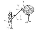
- the pole saw 500 mainly includes a long operation rod 501, an engine 502 provided on one end side of the operation rod 501, and a gear case 503 provided on the other end side of the operation rod 501.
- the force is transmitted to a gear in the gear case 503 through a shaft disposed in the operation rod 501, and the saw chain 504 attached to the gear case 503 is driven to circulate, thereby cutting the workpiece W such as a branch located at a high place. I do.
- a long operation rod with a shaft arranged inside, an engine provided on one end side of the operation rod, and the vicinity of the engine Mainly equipped with a throttle provided on the other end of the operation rod, and an output shaft provided on the gear case to which the tip tool can be attached and detached, and the user operates the throttle after driving the engine.
- a pruning machine is known in which the driving force of the engine is transmitted by the shaft and the output shaft starts to be driven, and the cutting work can be performed by driving the tip tool attached to the output shaft (Patent Document 2). ).
- the saw chain 504 for cutting the workpiece W is generally wider than a saw blade or the like, there is a problem that a large amount of chips are generated.
- the replacement of the saw chain 504 is not easy, and filling the oil tank (the chain oil for preventing seizure of the saw chain 504) takes time. It was.
- the axial extension line of the operation rod 501 and the saw chain 504 are displaced from each other, so that a moment is generated around the axis of the operation rod 501 and the operation may become difficult. There is a problem that an intuitive operation is difficult because the cutting work is performed by visually recognizing the workpiece W at a position shifted from the extension line 501.
- the throttle since the user who attaches / detaches the tip tool and the throttle which drives the output shaft are separated by the length of the operating rod, the user can move the throttle tool while the tip tool is attached / detached. It is not easy to pay attention. For this reason, when a user who attaches / detaches the tip tool while the engine is idling, tilts or moves the entire pruning machine, the throttle may be touched and operated by an unexpected obstacle. When the throttle is unexpectedly operated, there is a problem that the output shaft is driven and it is difficult to attach and detach the tip tool.
- a drive switch for driving the tip tool is not intended while the user is attaching or detaching the tip tool.
- the output shaft starts to be turned on and it becomes difficult to attach and detach the end tool.
- the output shaft may be driven unintentionally during the attachment / detachment of the tip tool, and the output shaft must be securely stopped when the tip tool is attached / detached. Was desired.
- the present invention can be operated intuitively, can suppress the generation of chips, does not need to be filled with oil (chain oil) in the oil tank, and can be replaced by a simple operation.
- the object is to provide possible work tools.
- the present invention also provides a work tool that prevents unintentional driving of the output shaft by stopping the drive source when the user attaches / detaches the tip tool, thereby improving convenience in attaching / detaching the tip tool.
- the purpose is to provide.
- the present invention provides a drive source, a drive shaft having one end connected to the drive source, which is rotationally driven by the drive force of the drive source, and a housing that covers the other end of the drive shaft. And a reciprocating motion conversion mechanism that is provided in the housing and converts the rotation of the drive shaft into a reciprocating motion, and is connected to the reciprocating motion converting mechanism and is reciprocated by the reciprocating motion converting mechanism.
- An output shaft capable of supporting the drive source on one end side, supporting the reciprocating motion conversion mechanism on the other end side, and disposing the drive shaft inside the output shaft.
- the side surface of the saw blade is substantially parallel to the plane in a state where the saw blade is attached to the output shaft.
- the moment centering on the operation rod can be suppressed, so that the operability can be improved.
- the reciprocating motion conversion mechanism is connected to the drive shaft, is rotationally driven by the drive shaft, and has a drive transmission shaft having an inclined shaft, and an oscillating portion attached to the inclined shaft and reciprocatingly driving the output shaft It is preferable to have.
- the output shaft can be reciprocated with a simple configuration.
- a guide sleeve that is swingably supported in the housing, and a guide member that is disposed in the housing and has a track surface that extends along the reciprocating direction of the output shaft.
- the shaft has a swing roller that is slidably reciprocated in the guide sleeve and can roll on the raceway surface, and a tip portion of the saw blade attached to the output shaft is provided with the swing roller. It is preferable that a trajectory according to the shape of the raceway surface is drawn by rolling on the raceway surface and the output shaft being driven to reciprocate.
- a vibration absorbing mechanism for reducing vibration generated due to the reciprocating motion of the output shaft is disposed in the casing.
- Such a configuration can reduce the vibration generated due to the reciprocating motion of the output shaft, so that the operability can be further improved.
- an attachment / detachment mechanism is provided at the end of the output shaft so that the saw blade can be attached / detached to / from the output shaft by being operated in a single direction.
- the present invention further includes a first housing, a long operation rod having one end connected to the first housing, a second housing connected to the other end of the operation rod, and the first housing
- a drive source housed in the housing, a drive shaft rotatably supported in the operation rod and driven to rotate by the drive source, and a drive shaft provided in the second housing, reciprocating the rotation of the drive shaft
- a reciprocating motion converting mechanism for converting into motion and an output shaft connected to the reciprocating motion converting mechanism, reciprocatingly driven by the reciprocating motion converting mechanism, and capable of attaching a saw blade, the saw blade being attached to the output shaft.
- a work tool characterized in that a side surface of the saw blade is substantially parallel to a plane including the operating rod and the output shaft in the attached state.
- the cutting operation can be performed with the saw blade, the amount of chips after cutting the material to be cut can be suppressed. Further, since it is not necessary to fill the oil tank with oil, the burden on the user can be reduced. Furthermore, since the moment around the operating rod can be suppressed, the operability can be improved.
- the present invention further includes a drive source, a drive shaft that is rotationally driven by the drive source being driven, a reciprocating motion conversion mechanism that converts the rotational force of the drive shaft into a reciprocating motion, An output shaft connected to the reciprocating motion conversion mechanism and driven to reciprocate by the rotational force of the drive shaft via the reciprocating motion converting mechanism, and provided on the output shaft, and fixing a tip tool to the output shaft A tool fixing mechanism; a fixing mechanism detection unit that detects a state of the tool fixing mechanism; and a stopping unit that stops driving of the drive source when the fixing mechanism detection unit detects a release operation.
- a work tool characterized by the above is provided.
- the tool fixing mechanism has an operation unit for releasing the fixing of the tip tool, and the fixing mechanism detecting unit releases the fixing of the tip tool when the operation unit is operated. It is preferable to be configured to detect this.
- the tool fixing mechanism includes a locking member that fixes the tip tool to the output shaft, and the locking member fixes the tip tool to the output shaft at a first position, The fixing of the tip tool to the output shaft is released at a position, and the fixing mechanism detection unit is configured to detect that the fixing of the tip tool is released by the position of the locking member. preferable.
- the stop means has a switch mechanism, and the fixing mechanism detection unit is pressed by the locking member when the locking member is in the first position, and the locking member
- the tool has a button that is not pressed by the locking member when in the second position, and the tool is not pressed by the locking member, so that the fixing of the tip tool is released. It is preferable that it is comprised so that it may detect.
- the drive source is an engine including an ignition coil having a primary winding and a secondary winding, and a power generator that supplies current to the primary winding.
- the current generated by the power generator is caused to flow through the primary winding by disconnecting the secondary winding and the ground, allowing the engine to be driven, and the fixing mechanism detection unit being released.
- the current generated by the power generation device is caused to flow through the ground by connecting the primary winding and the ground, and the supply of current to the primary winding is shut off.
- the engine is preferably configured to stop driving.
- the drive source is an electric motor connected to a power source through the stop unit, and the stop unit is in a state where it is not detected that the fixing mechanism detection unit has been released.
- the electric motor is supplied from the power source to the electric motor. It is preferable that the power supply is cut off and the driving of the electric motor is stopped or maintained in a stopped state.
- the present invention further includes a drive source, a drive shaft having one end connected to the drive source and driven to rotate when the drive source is driven, a housing covering the other end of the drive shaft, and one end side
- the driving source is supported at the other end
- the casing is supported at the other end
- a long operating rod is disposed inside the driving shaft, and is provided in the casing and is driven by the rotational force of the driving shaft.
- Output shaft, a tool fixing mechanism that is provided on the output shaft and fixes the tip tool to the output shaft, a fixing mechanism detection unit that detects the state of the tool fixing mechanism, and the fixing mechanism detection unit is released Provided is a work tool comprising stop means for stopping the drive of the drive source when it is detected that it has been operated.
- the work tool of the present invention it is possible to provide a work tool that improves operability and convenience and enables intuitive operation. Further, according to the work tool of the present invention, when the user attaches / detaches the tip tool, the drive source is stopped, the unintentional driving of the output shaft is prevented, and the convenience in attaching / detaching the tip tool is improved. be able to
- AA sectional drawing which shows the state by which the braid
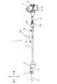
- a pole saver saw 1 as a work tool includes a housing 2 that covers a part of an internal combustion engine 2A, an operating rod 3 having a handle 33, The gear housing 4, the reciprocating motion conversion mechanism 5, the plunger 6, and the blade holder 7 are mainly configured, and are used in a state where the blade 8 is attached to the plunger 6.
- the direction in which the operating rod 3 extends with respect to the housing 2 is defined as the front direction, and the reverse direction is defined as the rear direction.
- the direction in which the handle 33 extends with respect to the operating rod 3 is defined as the upward direction, and the reverse direction is defined as the downward direction.
- the right when the pole saver saw 1 is viewed from the rear is defined as the right direction, and the reverse direction is defined as the left direction.
- the housing 2 covers a part of the internal combustion engine 2A corresponding to a drive source, and mainly includes a fuel tank 21 and a starter handle 22, and includes components necessary for driving the internal combustion engine 2A. Yes.
- the housing 2 is an example of the first housing of the present invention.
- the internal combustion engine 2A includes a rotating shaft (not shown) and a centrifugal clutch (not shown).
- a rotating shaft (not shown) is driven to rotate when the internal combustion engine 2A is driven.
- a centrifugal clutch (not shown) is connected to a rotating shaft (not shown).
- the fuel tank 21 is provided at the lower part of the housing 2, and contains fuel for driving the internal combustion engine 2A.
- the starter handle 22 is provided on the left side of the rear end portion of the housing 2.
- the operating rod 3 is a long cylindrical member extending in the front-rear direction, and is connected to the front part of the housing 2 and connected to the rear part of the gear housing 4, and the length in the front-rear direction is about 1 to 4 m. Designed. In other words, the operating rod 3 supports the housing 2 and the internal combustion engine 2A partially covered with the housing 2 at one end side (rear end side), and the gear housing 4 and the other end side (front end side). The reciprocating motion conversion mechanism 5 in the gear housing 4 is supported.
- the operating rod 3 includes a grip 31, a hanger 32, and a handle 33, and a drive shaft 34 shown in FIG.
- the grip 31 is a part that is gripped by the user, and is provided at the rear part of the operation rod 3.
- the grip 31 includes a throttle 31A and a stop switch 31B.
- the throttle 31A is provided on the lower side of the grip 31, and can adjust the fuel injection amount by making the amount pushed in the direction of the operating rod 3 variable.
- the stop switch 31B is a switch that is connected between, for example, an ignition plug and a power generator and can be switched between an operation position and a stop position.
- the internal combustion engine is pulled by switching the stop switch 31B to the operation position and pulling the starter handle 22. 2A can be driven. Further, the internal combustion engine 2A can be stopped by switching the stop switch 31B to the stop position while the internal combustion engine 2A is being driven.
- the hanger 32 is a part to which a shoulder band (not shown) is attached, and is provided in front of the grip 31. In a state where the shoulder band is attached to the hanger 32, the user uses the pole saver saw 1 by placing the shoulder band on the shoulder.
- the handle 33 is a so-called loop handle that is provided in front of the hanger 32 and has a ring shape when viewed from the front, and includes a gripping portion 33A and a connecting portion 33B.
- the gripping portion 33A is a portion that is gripped by a hand opposite to the hand that grips the grip 31, and has a bar shape extending in the left-right direction, and is positioned above the operation rod 3.
- the connecting portion 33B connects the left and right end portions of the gripping portion 33A and both side surfaces of the operating rod 3 respectively.
- the user uses the pole saver saw 1 while holding the shoulder band on the shoulder, holding the grip 31 with one hand, and holding the approximate center in the left-right direction of the holding portion 33A with the other hand.
- the gripping portion 33 ⁇ / b> A gripped by the user and the grip 31 are positioned on the axis of the operating rod 3 in a top view, so that stable operability is ensured.
- the drive shaft 34 is a shaft extending from the gear housing 4 to the housing 2 through the inside of the operation rod 3 in the front-rear direction, and is rotationally driven by the driving force of the internal combustion engine 2A.
- a rear end portion of the drive shaft 34 is connected to the internal combustion engine 2 ⁇ / b> A via a centrifugal clutch in the housing 2, and a front end portion is connected to the reciprocating motion conversion mechanism 5.
- the drive shaft 34 is rotatably supported by a ball bearing 4 ⁇ / b> A in the gear housing 4, a ball bearing (not shown) in the operation rod 3, and a ball bearing (not shown) in the housing 2.
- the portion is provided with a pinion 34A.
- the gear housing 4 corresponding to the housing is connected to the front end portion of the operation rod 3, and a reciprocating motion conversion mechanism 5 and a plunger 6 are mainly accommodated therein.
- the gear housing 4 is an example of the second housing of the present invention.
- the reciprocating motion conversion mechanism 5 is disposed in the lower part inside the gear housing 4 and includes a drive transmission shaft 51 and a reciprocating plate 52 corresponding to a swinging portion.
- the drive transmission shaft 51 extends in the front-rear direction substantially parallel to the drive shaft 34, and is positioned in front of and below the drive shaft 34, and is rotatably supported by the ball bearing 4B and the ball bearing 4C supported by the gear housing 4. Has been.
- the drive transmission shaft 51 includes a drive transmission gear 51A and an inclined shaft 51B.
- the drive transmission gear 51A is coaxially fixed to the rear portion of the drive transmission shaft 51 and meshes with the pinion 34A of the drive shaft 34.
- the rotational force of the drive shaft 34 is transmitted to the drive transmission shaft 51 via the pinion 34A and the drive transmission gear 51A.
- the inclined shaft 51B is provided on the drive transmission shaft 51 in a state where the axis of the inclined shaft 51B is inclined with respect to the axis of the drive transmission shaft 51.
- the inclined shaft 51B is configured to rotate with the drive transmission shaft 51 around the axis of the drive transmission shaft 51.
- the reciprocating plate 52 is rotatably attached to the inclined shaft 51B via two ball bearings 5A that are in contact with the inclined shaft 51B and extends in a direction perpendicular to the axis of the inclined shaft 51B. 52A.
- the tip of the swing arm 52A is connected to the plunger 6.
- the plunger 6 corresponding to the output shaft has a substantially cylindrical shape extending in the front-rear direction, is positioned in front of and above the drive shaft 34, and has a substantially parallel positional relationship with the drive shaft 34.
- the plunger 6 is supported by the gear housing 4 so as to be reciprocally slidable in the front-rear direction via a metal bearing 4D. Further, the plunger 6 is formed with an insertion hole 6 a and a blade attachment portion 61.
- the insertion hole 6a is formed in a substantially circular shape in the bottom view of the rear portion of the plunger 6, and a part of the swing arm portion 52A of the reciprocating plate 52 is inserted therethrough.
- the tip of the swing arm part 52A is rotatably connected to the plunger 6 by a connector pin 6A penetrating the rear part of the plunger 6 left and right.
- the blade attachment portion 61 is formed at the front end portion of the plunger 6, and a slit 61a, an attachment hole 61b, and a pin insertion hole portion 61c are formed.
- the slit 61a is a hole penetrating in the up-down direction extending rearward from the front end surface of the blade mounting portion 61, and is configured such that the rear end portion of the blade 8 can be inserted.
- the mounting hole 61b is a hole penetrating in the left-right direction behind the slit 61a, and allows a fastening member 7A described later to pass therethrough.
- the pin insertion hole 61c is a circular hole in a side view that penetrates from the front left side of the blade mounting portion 61 to the slit 61a, and has a reduced diameter hole portion 61d having a small hole diameter in the vicinity of the slit 61a. is doing.
- a stepped portion 61A is formed on the outer periphery of the reduced diameter hole portion 61d.
- the blade holder 7 is fixed to the blade mounting portion 61 by a fastening member 7A, and includes a locking pin 71, a knob 72, and a holder case 73.
- a blade 8 corresponding to a saw blade attached to the plunger 6 extends in the front-rear direction and includes a blade portion for cutting a material to be cut at a front lower end portion.
- the blade 8 has a thickness of about 0.9 to 1.6 mm, and a locking hole 8a is formed at the rear end thereof.
- the locking pin 71 includes a first cylindrical portion 71A, a second cylindrical portion 71B, and a conical portion 71C.
- the first cylindrical portion 71A has a cylindrical shape extending in the left-right direction, and the length in the left-right direction is designed to be shorter than the width in the left-right direction of the slit 61a.
- the first cylindrical portion 71 ⁇ / b> A is inserted through the locking hole 8 a of the blade 8 and fixes the blade 8 to the blade mounting portion 61.
- the second cylindrical portion 71B has a cylindrical shape having a diameter larger than the diameter of the first cylindrical portion 71A, and the diameter is configured to be slightly smaller than the diameter of the reduced diameter hole portion 61d.
- the conical portion 71C has a shape in which a conical shape is connected to a cylindrical shape, and a portion on the cylindrical shape is larger than the diameter of the second cylindrical portion 71B and slightly smaller than the diameter of the pin insertion hole portion 61c. have.
- a spring 7B is provided on the outer side in the radial direction of the second cylindrical portion 71B. One end portion in the left-right direction contacts the conical portion 71C, and the other end contacts the stepped portion 61A of the pin insertion hole portion 61c. It touches.
- the spring 7B biases the locking pin 71 in a direction (left direction) in which the blade 8 is not fixed to the blade mounting portion 61.
- the knob 72 includes a spring accommodating portion 72A, an arm portion 72B, a protruding portion 72C, and an operation portion 72D.
- the spring accommodating portion 72A has a substantially circular shape when viewed from the side, and a coil spring 72E is accommodated therein, and a through hole 72a that allows the fastening member 7A to penetrate is formed on the left side surface.
- the arm portion 72B extends forward from the front upper portion of the spring accommodating portion 72A, and the surface facing the pin insertion hole portion 61c of the blade mounting portion 61 is inclined to the left as it goes from below to above.
- a surface 71F is defined.
- the inclined surface 71F is in contact with the conical portion 71C of the locking pin 71, and restricts the locking pin 71 from moving to the left than in the state of FIG.
- the coil spring 72E biases the arm portion 72B upward. That is, the coil spring 72E maintains a state where the arm portion 72B restricts the movement of the locking pin 71 in the left direction (the state shown in FIG. 4).
- the protruding portion 72C protrudes leftward from the front left side surface of the arm portion 72B, and an operation portion 72D is provided at the left end portion thereof.
- the holder case 73 is formed so as to cover the entire blade mounting portion 61, and a portion facing the slit 61a on the front end surface is opened in the vertical direction.
- a portion of the knob 72 that faces the protruding portion 72C is formed with a hole that allows the protruding portion 72C to protrude leftward.
- a through hole 73 a that allows the fastening member 7 ⁇ / b> A to pass therethrough is formed in the rear portion of the right side surface of the holder case 73.
- the blade 8 is attached to the blade attachment portion 61.
- the knob 72 is pushed downward, the locking pin 71 is moved leftward along the inclined portion 72F by the urging force of the spring 7B.
- the first cylindrical portion 71A moves out of the locking hole 8a, and the blade 8 is fixed to the blade mounting portion 61. That is, the blade 8 can be removed from the blade mounting portion 61 only by an operation of pushing down the knob 72 downward.
- the knob 72 is pushed downward, the blade 8 is inserted into the slit 61a with the locking pin 71 moved to the left, and the knob 72 is released.
- the knob 72 is returned to the state shown in FIG. 4 by the coil spring 72E, and the blade 8 is fixed to the blade mounting portion 61.
- the blade attachment portion 61 and the blade holder 7 constitute an attachment / detachment mechanism, and the blade 8 can be attached to and detached from the plunger 6 by a simple procedure of operating the knob 72 in a single direction, so-called one-touch. Yes.
- the thin blade 8 can be attached to the plunger 6 to perform the cutting operation, the amount of chips generated can be suppressed as compared with a work tool that performs the cutting operation by attaching a saw chain or the like.
- the blade 8 may be cut by mistake other than the material to be cut located on the opposite side of the material to be cut with respect to the saw chain or the like. Since the blade portion is formed only on the surface, it is possible to suppress erroneous cutting other than the material to be cut.
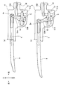
- the plane B represents a plane including the operation rod 3 and the plunger 6, and the plane B and the side surface 8 ⁇ / b> A of the blade 8 are in a parallel positional relationship.
- the straight line A represents a straight line including the axis of the operation rod 3, and the straight line A and the blade 8 are separated from each other in a side view.
- the drive transmission shaft 51 When the drive shaft 34 rotates, the drive transmission shaft 51 is rotationally driven via the pinion 34A and the drive transmission gear 51A, and the inclined shaft 51B rotates around the axis of the drive transmission shaft 51.
- a pole saver saw 200 according to a second embodiment of the present invention will be described with reference to FIGS.
- symbol is attached
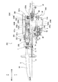
- a guide sleeve 201 is disposed in front of and above the drive shaft 34 so as to be swingable by a predetermined angle around the shaft bolt 202. Further, guide rails 209 are supported by the gear housing 204 on the outer sides of the guide sleeve 201 in the left-right direction.
- the gear housing 204 is an example of a housing of the present invention and an example of a second housing.
- the guide sleeve 201 has a substantially cylindrical shape extending in the front-rear direction, and a bearing metal 203 is press-fitted inside the front thereof.
- Guide holes 201a extending in the front-rear direction are formed in the left and right side surfaces at the center of the guide sleeve 201 in the front-rear direction, and rectangular through holes 201b having a rectangular shape in side view are formed in the left and right side surfaces of the rear end portion.
- elongated holes 201c extending in the front-rear direction are formed on both upper and lower surfaces of the guide sleeve 201.
- the guide sleeve 201 supports a plunger 206 in the interior thereof via a bearing metal 203 so as to be slidable in the front-rear direction.
- the plunger 206 corresponding to the output shaft extends in the front-rear direction, the blade holder 7 is fixed to the front end thereof, and the blade 8 is detachable.
- Guide shafts 206A extending in the left-right direction from the left and right side surfaces of the rear portion of the plunger 206 are inserted through the guide holes 201a on the left and right side surfaces of the guide sleeve 201 and extend to the outside of the guide sleeves 201.
- a swing roller 206B is provided that is rotatable about the axis of the guide shaft 206A.
- a plunger through hole 206a extending in the front-rear direction is formed on the lower surface of the plunger 206, and a substantially circular circular hole 206b is formed on the upper surface when viewed from the top.
- the swing arm portion 52A of the reciprocating plate 52 passes through the elongated hole 201c and the plunger through hole 206a, and a spherical portion 252B formed at the end of the swing arm portion 52A engages with the circular hole 206b in a rollable manner. Yes.
- a change shaft 205 that passes through the respective rectangular through holes 201b on the left and right side surfaces of the guide sleeve 201 is supported by the gear housing 204 so as to be rotatable about its own axis.
- the portion of the change shaft 205 that passes through the rectangular through hole 201b has a flat plate shape having a flat portion.
- a change lever 205A connected to the change shaft 205 is provided at the rear side of the right side surface of the gear housing 204.
- the state in FIG. 7 is a state in which the swing operation of the guide sleeve 201 is allowed.
- the guide rail 209 corresponding to the guide member is configured by a lower rail 209B having a raceway surface 209A that can come into contact with the swing roller 206B and an upper rail 209D having a raceway surface 209C that can come into contact with the swing roller 206B.
- the lower rail 209B and the upper rail 209D are connected at their front end portions.
- the raceway surface 209A extends in the front-rear direction (reciprocating direction), and gradually inclines downward from the rear toward the front. Further, the raceway surface 209C extends in the front-rear direction (reciprocating direction), and gradually inclines upward from the rear part toward the front part.
- pole saver saw 200 The operation of the pole saver saw 200 according to the second embodiment of the present invention will be described with reference to FIG.
- the drive shaft 34 rotates as in the pole saver saw 1 according to the first embodiment of the present invention.
- the rotational force of the drive shaft 34 is transmitted to the reciprocating plate 52 via the drive transmission shaft 51 and the inclined shaft 51B, and the swing arm portion 52A swings in the front-rear direction.
- the swinging arm portion 52A swings, the spherical portion 252B engaged with the inside of the circular hole 206b so as to be able to roll with a slight gap performs a reciprocating motion in the front-rear direction while rolling.
- the blade 8 is reciprocally driven. Cutting operation is enabled by the reciprocating drive of the blade 8.
- the blade 8 and the plunger 206 are reciprocated similarly to the pole saver saw 1 according to the first embodiment of the present invention. I do. That is, only the movement in the front-rear direction is performed, and the movement in the vertical direction is not added.
- the blade 8 receives an upward reaction force F from the material X to be cut. Moves upward. Further, since the guide sleeve 201 can swing around the shaft bolt 202, the rear end portion of the guide sleeve 201 is pressed downward, and the swing roller 206B contacts the raceway surface 209A of the guide rail 209.
- the pole saver saw 200 is provided with an orbital mechanism for realizing so-called orbital cutting that adds a downward movement to the tip of the blade 8 when returning from the front dead center to the rear dead center. Therefore, the cutting force can be improved.
- a pole saver saw 300 according to a third embodiment of the present invention will be described with reference to FIGS.
- symbol is attached
- the configuration will be described.
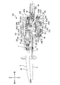
- a reciprocating motion conversion mechanism 305 and a counterweight 301 are disposed in the gear housing 304 of the pole saver saw 300.
- the gear housing 304 is an example of a housing of the present invention and an example of a second housing.
- the reciprocating motion conversion mechanism 305 is disposed in the lower part inside the gear housing 304 and includes a drive transmission shaft 51 and a counter reciprocating plate 352.
- the drive transmission shaft 51 includes a counter tilt shaft 351B behind the tilt shaft 51B, and the counter tilt shaft 351B is configured to rotate around the axis of the drive transmission shaft 51 with the drive transmission shaft 51.
- the counter reciprocating plate 352 is rotatably attached to the counter tilt shaft 351B via two ball bearings 305A that contact the counter tilt shaft 351B, and extends in a direction perpendicular to the axis of the counter tilt shaft 351B.
- a counter swing arm 352A is provided.
- a counter spherical portion 352B is provided at the tip of the counter swing arm portion 352A, and the counter spherical portion 352B is connected to the counter weight 301.
- the counter reciprocating plate 352 is tilted to the right by a predetermined angle with respect to the reciprocating plate 52.
- the inclination of the counter inclination shaft 351B with respect to the drive transmission shaft 51 is determined in consideration of the above-mentioned predetermined angle so that the swinging motion of the counter reciprocating plate 352 and the reciprocating plate 52 is in reverse phase. .
- the counterweight 301 has a substantially bowl shape that opens downward in a rear view and includes a guide sleeve 201. Further, the cross-sectional shape of the counterweight 301 is designed so that the center of gravity of the counterweight 301 and the center of gravity of the plunger 206 substantially coincide with each other in the rear view. Furthermore, in order to substantially eliminate the vibration in the axial direction of the plunger 206, it is achieved by making the product of the mass of the counterweight 301 and the reciprocating amount equal to the product of the mass of the plunger 206 and the reciprocating amount.
- the counterweight 301 is an example of the vibration absorbing mechanism of the present invention.
- the counterweight 301 is supported by a countershaft 302 provided in the gear housing 304 so as to be slidable in the front-rear direction.
- a connecting recess recessed upward is formed at the lower rear lower end of the counterweight 301, and the counter spherical portion 352B of the counter reciprocating plate 352 engages with a slight gap so that it can roll.
- the drive shaft 34 rotates as in the pole saver saw 1 according to the first embodiment of the present invention.
- the rotational force of the drive shaft 34 is transmitted to the reciprocating plate 52 and the counter reciprocating plate 352 via the drive transmission shaft 51, the tilt shaft 51B, and the counter tilt shaft 351B, and the swing arm portion 52A and the counter swing arm portion 352A are moved in the front-rear direction. Swing. Since the swinging arm portion 52A swings, the spherical portion 252B engaged with the inside of the circular hole 206b so as to be able to roll with a slight gap performs a reciprocating motion in the front-rear direction while rolling. 206 and the blade 8 are driven to reciprocate.
- the pole saver saw 300 is provided with a counterweight mechanism in which the plunger 206 and the counterweight 301 reciprocate in opposite phases, so that vibrations caused by the reciprocating motion of the plunger 206 are reduced. Therefore, the operability can be further improved.
- a pole saver saw 400 according to a fourth embodiment of the present invention will be described with reference to FIG.
- symbol is attached
- the pole saver saw 400 houses an electric motor 401 corresponding to a drive source in the housing 2.
- the electric motor 401 has a rotating shaft (not shown). When the electric motor 401 is driven, the rotating shaft (not shown) is driven to rotate.
- the grip 31 includes a trigger 431A and a power switch 431B.
- a pole saver saw 601 that is a work tool according to a fifth embodiment of the present invention includes an internal combustion engine 602, an operating rod 603 having a handle 633, a gear housing 604, a plunger 606,
- the blade holder 607 is mainly used, and is used in a state where the blade 608 is attached to the plunger 606.
- the direction in which the operating rod 603 extends with respect to the internal combustion engine 602 is defined as the front direction, and the reverse direction is defined as the rear direction.
- the direction in which the handle 633 extends with respect to the operating rod 603 is defined as the upward direction, and the reverse direction is defined as the downward direction.
- the right is defined as the right direction
- the reverse direction is defined as the left direction.
- the internal combustion engine 602 is a two-cycle small engine, and includes a crankshaft 621, a magnet rotor 622, a centrifugal clutch 623, an ignition coil 624, a spark plug 625, a starter handle 626, and the like. And a fuel tank 627 and parts necessary for driving the internal combustion engine 602 such as a piston (not shown), a crank mechanism (not shown), and a carburetor (not shown).
- the internal combustion engine 602 corresponds to a drive source.
- the crankshaft 621 is an axis extending in the front-rear direction, and is connected to a crank mechanism (not shown) that converts a reciprocating motion of a piston (not shown) into a rotational motion.
- a crank mechanism not shown
- the crankshaft 621 is rotated by transmitting a driving force of a piston (not shown) via a crank mechanism (not shown).
- the magnet rotor 622 is configured in a substantially disc shape and is fixed to the front portion of the crankshaft 621 so as to rotate coaxially and integrally, and includes a magnet 622A, a magnetic pole piece 622B, Counter weight 622C.
- the magnet 622A is composed of a permanent magnet, and is sandwiched between a pair of magnetic pole pieces 622B slightly inside the peripheral edge of the magnet rotor 622.
- the counterweight 622C is provided on the opposite side of the magnet 622A with respect to the center of the magnet rotor 622, and corrects the mass distribution bias of the entire magnet rotor 622 by the magnet 622A.
- 17 is a known current generator mainly composed of a current generating coil (not shown) provided in the vicinity of the magnet rotor 622 and the magnet rotor 622.
- a current generating coil (not shown) provided in the vicinity of the magnet rotor 622 and the magnet rotor 622.
- the centrifugal clutch 623 is attached to the front side of the magnet rotor 622, and mainly includes a clutch weight 623A, a clutch drum 623B, and a clutch shaft 623C.
- the centrifugal clutch 623 is connected to the clutch drum 623B by moving the clutch weight 623A radially outward of the rotation center axis by centrifugal force when the rotational speed of the magnet rotor 622 exceeds a predetermined rotational speed.
- This is a known device in which the rotational force of the magnet rotor 622 is transmitted to the clutch drum 623B, and the clutch shaft 623C provided in the front center of the clutch drum 623B and extending in the front-rear direction is rotationally driven.
- the ignition coil 624 is provided above the magnet rotor 622, and has a primary winding 624A and a secondary winding 624B inside. Yes.
- Primary winding 624A is connected to a current generating coil (not shown) of power generation device 628, and secondary winding 624B is connected to spark plug 625.
- a current generated by a current generating coil (not shown) flows in the primary winding 624A, and a high voltage is induced in the secondary winding 624B by the mutual induction action, and the spark plug 625 is activated to ignite.
- the spark plug 625 is provided in the upper part of the internal combustion engine 602.
- the spark plug 625 ignites once every rotation of the magnet rotor 622 and pushes down a piston (not shown).
- the ignition coil 624 is an example of the ignition coil of the present invention.
- the starter handle 626 is provided on the left side of the rear end of the internal combustion engine 602 and is connected to one end of a rope (not shown). The other end of the rope is wound around a reel (not shown) that can be connected to the crankshaft 621 via a clutch. When the user pulls the starter handle 626, the reel rotates in accordance with the amount of the rope that is pulled out.
- the magnet rotor 622 can be rotated together with the shaft 621.
- the fuel tank 627 is provided in the lower part of the internal combustion engine 602, and contains fuel for driving the internal combustion engine 602.
- the operating rod 603 is a long cylindrical member extending in the front-rear direction, and is connected to the front portion of the internal combustion engine 602, in other words, the operating rod 603 has one end side thereof.
- the internal combustion engine 602 is supported on the (rear end side), and the length in the front-rear direction is designed to be about 1 to 4 m.
- the operating rod 603 includes a grip 631, a hanger 632, and a handle 633, and a drive shaft 634 is disposed therein.
- the grip 631 is a part gripped by the user, and is provided at the rear part of the operation rod 603.
- the grip 631 includes a throttle 631A, a stop switch 631B, a machine-side terminal block 631C, and a ground-side terminal block 631D.
- the throttle 631A is provided on the lower side of the grip 631, and is connected to a carburetor (not shown) via a wire 631E.
- the throttle 631A can adjust the fuel injection amount by changing the amount pushed upward.
- the machine-side terminal block 631 ⁇ / b> C and the ground-side terminal block 631 ⁇ / b> D are provided inside the grip 631.
- the machine-side terminal block 631C is connected between the ignition coil 624 and the power generator 628 by a connection line 631H.
- the ground side terminal block 631D is connected to the body ground of the internal combustion engine 602 by a connection line 631I.
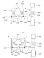
- the stop switch 631B is a switch that can be switched between an operation position and a stop position, and includes connection points 631a and 631b that are provided on the upper front side of the grip 631 and configured to be connected to each other.
- the connection point 631a of the stop switch 631B is connected to the machine-side terminal block 631C by a connection line 631F, and the connection point 631a between the ignition coil 624 and the power generator 628 is connected to the connection line 631F, the machine-side terminal block 631C, and The connection is made via the connection line 631H.
- connection point 631b of the stop switch 631B is connected to the ground side terminal block 631D by the connection line 631G, and the body ground of the internal combustion engine 602 and the connection point 631b are connected to the connection line 631G, the ground side terminal block 631D, and the connection line. 631I is connected.
- connection point 631a and the connection point 631b are electrically connected, and there is a connection line 631H between the ignition coil 624 and the power generator 628, the machine side.
- the terminal block 631C, the connection line 631F, the stop switch 631B, the connection line 631G, the ground side terminal block 631D, and the connection line 631I are electrically connected to the body ground.
- the connection point 631a and the connection point 631b are electrically disconnected, and the ignition coil 624 and the power generator 628 are not electrically connected to the body ground. Connected.
- the hanger 632 is a portion to which a shoulder band (not shown) is attached, and is provided in front of the grip 631. With the shoulder band attached to the hanger 632, the user uses the pole saver saw 601 with the shoulder band on the shoulder.
- the handle 633 is a so-called loop handle that is provided in front of the hanger 632 and has a ring shape when viewed from the front, and includes a grip portion 633A and a connection portion 633B.
- the grip portion 633A is a portion that is gripped by the other hand when the user grips the grip 631, and has a bar shape extending in the left-right direction, and is positioned above the operation rod 603.
- the connection portion 633B connects the left and right end portions of the grip portion 633A and the both side surfaces of the operating rod 603, respectively.
- the user uses the pole saver saw 601 in a state where the shoulder band is hung on the shoulder, the grip 631 is gripped by one hand, and the gripping portion 633A is gripped at the approximate center in the left-right direction.
- the drive shaft 634 is a shaft extending in the front-rear direction from the gear housing 604 through the inside of the operation rod 603 to the internal combustion engine 602, and the rear end portion is connected to the clutch shaft 623 ⁇ / b> C of the centrifugal clutch 623.
- the front end is connected to the reciprocating motion conversion mechanism 605.
- the drive shaft 634 is configured to rotate with the clutch shaft 623C.
- the drive shaft 634 is rotatably supported by a ball bearing 604A in the gear housing 604 and a ball bearing (not shown) in the operation rod 603, and a pinion 634A is provided at the front end of the drive shaft 634. Yes.
- the gear housing 604 is connected to a front end portion of the operation rod 603, and a reciprocating motion conversion mechanism 605 and a plunger 606 are mainly accommodated therein.
- the gear housing 604 is supported by the operation rod 603 on the other end side (front end side) of the operation rod 603.
- the gear housing 604 corresponds to a housing.
- the reciprocating motion conversion mechanism 605 is disposed on the lower side inside the gear housing 604, and includes a drive transmission shaft 651 and a reciprocating plate 652 as a swinging portion.
- the drive transmission shaft 651 extends in the front-rear direction substantially parallel to the drive shaft 634, is positioned in front of and below the drive shaft 634, and is rotatably supported by the ball bearing 604B and the ball bearing 604C supported by the gear housing 604. Has been.
- the drive transmission shaft 651 includes a drive transmission gear 651A and an inclined shaft 651B.
- the drive transmission gear 651A is coaxially fixed to the rear part of the drive transmission shaft 651 and meshes with the pinion 634A of the drive shaft 634.
- the rotational force of the drive shaft 634 is transmitted to the drive transmission shaft 651 via the pinion 634A and the drive transmission gear 651A.
- the inclined shaft 651B is provided on the drive transmission shaft 651 in a state where the axis of the inclined shaft 651B is inclined with respect to the axis of the drive transmission shaft 651.
- the inclined shaft 651B is configured to rotate with the drive transmission shaft 651 around the axis of the drive transmission shaft 651.
- the reciprocating plate 652 is rotatably attached to the inclined shaft 651B via two ball bearings 605A that abut against the inclined shaft 651B and extends in a direction substantially perpendicular to the axis of the inclined shaft 651B.
- a portion 652A is provided.
- the distal end portion of the swing arm portion 652 ⁇ / b> A is connected to the plunger 606.
- the plunger 606 has a substantially cylindrical shape extending in the front-rear direction, is located in front of and above the drive shaft 634, and has a substantially parallel positional relationship with the drive shaft 634.
- the plunger 606 is supported by the gear housing 604 so as to be slidable back and forth in the front-rear direction via a metal bearing 604D. Further, the plunger 606 is formed with an insertion hole 606a and a blade attachment portion 661.
- the plunger 606 corresponds to an output shaft.
- the insertion hole 606a is formed in a substantially circular shape when viewed from the bottom on the lower rear side of the plunger 606, and a part of the swing arm portion 652A of the reciprocating plate 652 is inserted therethrough.
- the distal end portion of the swing arm portion 652A is rotatably connected to the plunger 606 by a connector pin 606A penetrating the rear portion of the plunger 606 left and right.
- the blade attachment portion 661 is formed at the front end portion of the plunger 606, and has a slit 661a, a fastening hole 661b, a pin insertion hole portion 661c, and a through hole 661e.
- the slit 661a is a hole penetrating in the vertical direction extending rearward from the front end surface of the blade mounting portion 661, and is configured such that the rear end portion of the blade 608 can be inserted.
- the fastening hole 661b is a hole that is formed in the left-right direction and is formed behind the slit 661a, and allows a fastening member 607A described later to pass therethrough.
- the pin insertion hole 661c is a circular hole in a side view that penetrates from the front left side of the blade mounting portion 661 to the slit 661a, and has a reduced-diameter hole portion 661d having a small hole diameter in the vicinity of the slit 661a. is doing. Further, a stepped portion 661A is formed on the outer side in the radial direction of the reduced diameter hole portion 661d.
- the through hole 661e is a hole that penetrates from the right side surface of the blade mounting portion 661 to the slit 661a, and is opposed to the reduced diameter hole portion 661d, and the push button 673A of the micro switch 673 described later protrudes to the left. Allowed.
- the blade holder 607 is fixed to the blade attachment portion 661 by a fastening member 607A, and includes a locking pin 671, a knob 672, a micro switch 673, and a holder case 674.
- the blade 608 attached to the plunger 606 extends in the front-rear direction and includes a blade portion for cutting the material to be cut at the front lower end portion.
- the vertical length of the rear portion of the blade 608 inserted into the slit 661a of the blade mounting portion 661 is substantially the same as the vertical length of the blade mounting portion 661.
- the blade 608 has a thickness of about 0.9 to 1.6 mm, and a circular engagement hole 608a is formed in the rear portion thereof in a side view penetrating in the left-right direction.
- the blade holder 607 corresponds to a tool fixing mechanism, and the blade 608 corresponds to a tip tool.
- the locking pin 671 includes a first cylindrical portion 671A, a second cylindrical portion 671B, and a conical portion 671C.
- the first cylindrical portion 671A has a cylindrical shape extending in the left-right direction, and the length in the left-right direction is designed to be shorter than the width in the left-right direction of the slit 661a.
- the first cylindrical portion 671A is inserted through the locking hole 608a of the blade 608, and the blade 608 moves in the front-rear direction with respect to the blade mounting portion 661 by inserting the first cylindrical portion 671A into the locking hole 608a. Movement is regulated.
- the second cylindrical portion 671B has a cylindrical shape having a diameter larger than the diameter of the first cylindrical portion 671A, and the diameter is configured to be slightly smaller than the diameter of the reduced diameter hole portion 661d.
- the conical portion 671C has a shape in which a conical shape is connected to a cylindrical shape, and the cylindrical portion has a diameter that is larger than the diameter of the second cylindrical portion 671B and slightly smaller than the diameter of the pin insertion hole portion 661c.
- a spring 607B is provided radially outward of the second cylindrical portion 671B, one end in the left-right direction abuts on the conical portion 671C, and the other end contacts the stepped portion 661A of the pin insertion hole 661c. It touches.
- the spring 607B biases the locking pin 671 in a direction (left direction) in which the fixing (regulation) of the blade 608 with respect to the blade mounting portion 661 is released.
- the locking pin 671 corresponds to a locking member.
- the knob 672 includes a spring accommodating portion 672A, an arm portion 672B, a protruding portion 672C, and a fixing release lever 672D.
- the spring accommodating portion 672A has a substantially circular shape when viewed from the side, a coil spring 672E is accommodated therein, and a fastening hole 672a that allows the fastening member 607A to pass therethrough is formed on the left side.
- the arm portion 672B extends forward from the upper front portion of the spring accommodating portion 672A, and the surface facing the pin insertion hole portion 661c of the blade mounting portion 661 is inclined to the left as it goes upward from below.
- a surface 672F is defined.
- the inclined surface 672F is in contact with the conical portion 671C of the locking pin 671 and restricts the locking pin 671 from moving to the left than the state of FIG. 20 by the urging force of the spring 607B.
- the coil spring 672E biases the arm portion 672B upward. That is, the coil spring 672E holds the state where the arm portion 672B restricts the movement of the locking pin 671 in the left direction (the state shown in FIG. 20).
- the protruding portion 672C protrudes leftward from the front left side surface of the arm portion 672B, and a fixing release lever 672D is provided at the left end portion thereof.
- the knob 672 corresponds to an operation unit.
- the microswitch 673 is a switch mechanism having a substantially rectangular parallelepiped shape provided on the right side of the blade mounting portion 661, and includes a push button 673A, and internally includes connection points 673a and 673b.
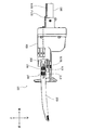
- the push button 673A is provided on the front left side surface of the micro switch 673 and protrudes leftward through a through hole 661e from a position facing the right end surface of the first cylindrical portion 671A of the locking pin 671. Yes. Further, the push button 673A has a state in which the first cylindrical portion 671A of the locking pin 671 is inserted into the locking hole 608a of the blade 608 and the blade 608 is fixed to the blade mounting portion 661 (state of FIG. 20). It is pressed by the locking pin 671.
- the micro switch 673 corresponds to a fixing mechanism detection unit, a stopping unit, and a switch mechanism.
- the push button 673A corresponds to a button.
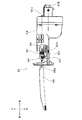
- connection points 673a and 673b are configured to be connectable to each other, the connection point 673a is connected to the machine-side terminal block 631C by a connection line 631J, and the connection point 673b is The connection line 631K is connected to the ground side terminal block 631D. Further, when the push button 673A is pressed by the locking pin 671 (the state shown in FIG. 20), the connection points 673a and 673b are not connected to each other (the state shown in FIG. 17A). When not pressed by the locking pin 671 (the state shown in FIG. 22), they are connected to each other (the state shown in FIG. 17B).
- the position of the locking pin 671 in the state where the locking pin 671 is pressing the push button 673A is an example of the first position of the present invention. Further, the position of the locking pin 671 in a state where the locking pin 671 does not press the push button 673A (the state of FIG. 22) is an example of the second position of the present invention.
- connection point 673a and the connection point 673b are in an electrically connected state. Therefore, a connection line is provided between the ignition coil 624 and the power generator 628.
- 631H, the machine side terminal block 631C, the connection line 631J, the micro switch 673, the connection line 631K, the ground side terminal block 631D, and the connection line 631I are electrically connected to the body ground.
- the connection point 673a and the connection point 673b are electrically disconnected, so that the body ground is between the ignition coil 624 and the power generator 628. And electrically disconnected.
- the holder case 674 is formed so as to cover the entire blade mounting portion 661 and the micro switch 673, and a portion facing the slit 661a on the front end surface is opened in the vertical direction. Further, in a state where the rear portion of the blade 608 is inserted into the slit 661a of the blade attachment portion 661, the upper inner side of the holder case 674 is in contact with the upper upper end surface of the blade 608, and the lower inner side of the holder case 674 is the lower end surface of the rear portion of the blade 608. By abutting, the movement of the blade 608 in the vertical direction with respect to the blade mounting portion 661 is restricted.
- a portion of the blade 608 facing the protrusion 672C of the knob 672 is formed with a hole that allows the protrusion 672C to protrude leftward and allows the protrusion 672C to move downward by a predetermined distance.
- a through hole 674a that allows the fastening member 607A to pass therethrough is formed in the rear portion of the right side surface of the holder case 674.
- the blade 608 moves in the front-rear direction with respect to the blade mounting portion 661.
- the movement in the vertical direction is restricted, and the blade 608 is fixed to the blade mounting portion 661.
- the blade 608 is attached to the blade attachment portion 661.
- the locking pin 671 is moved along the inclined surface 672F by the urging force of the spring 607B by pushing the knob 672 downward.
- the first cylindrical portion 671A comes out of the locking hole 608a, and the fixing of the blade 608 to the blade mounting portion 661 is released.
- the blade 608 can be detached from the blade mounting portion 661 only by pressing the knob 672 downward.
- the rear portion of the blade 608 is inserted into the slit 661a with the knob 672 pushed downward to move the locking pin 671 to the left, Release.
- the knob 672 biased upward by the coil spring 672E moves upward.
- the locking pin 671 moves rightward along the inclined surface 672F, so that the first cylindrical portion 671A is inserted into the locking hole 608a of the blade 608, and the push button of the micro switch 673 673A is pressed by the first cylindrical portion 671A, and the blade 608 is fixed to the blade mounting portion 661.
- the blade 608 can be attached to and detached from the plunger 606 without using a tool with a simple procedure of operating the knob 672 of the blade holder 607 in a single direction, so-called one-touch.
- the operation of the micro switch 673 is such that the push button 673A of the micro switch 673 is not pressed by the locking pin 671 when the knob 672 is operated downward and the blade 608 is not fixed to the blade mounting portion 661.
- the connection point 673a and the connection point 673b are in a connected state (the state shown in FIG. 17B).
- the stop switch 631B is switched from the stop position to the operation position.
- the electrical connection inside the pole saver saw 601 in this state is as shown in FIG. 17A, and the ignition coil 624 and the power generator 628 are not electrically connected to the body ground. Yes.
- Arrows J, K, and L shown in FIG. 17 indicate the direction of current flow in each state.
- crankshaft 621 When the internal combustion engine 602 starts driving, the crankshaft 621 is driven to rotate at a low rotational speed and enters an idling state.
- the throttle 631A When the throttle 631A is pushed upward in the idling state, the rotational speed of the crankshaft 621 increases.
- the clutch weight 623A of the centrifugal clutch 623 is connected to the clutch drum 623B.
- a clutch shaft 623C provided on the clutch drum 623B is rotationally driven.
- the drive shaft 634 connected to the clutch shaft 623C is rotationally driven.
- the drive transmission shaft 651 is rotationally driven via the pinion 634A and the drive transmission gear 651A, and the inclined shaft 651B rotates around the axis of the drive transmission shaft 651.
- the reciprocating plate 652 swings back and forth to reciprocate, and the plunger 606 and the plunger 606 connected to the swing arm portion 652A
- the attached blade 608 is also driven to reciprocate in the front-rear direction. Cutting operation is enabled by the reciprocating drive of the blade 608.
- the user When performing attachment / detachment during work, the user releases the throttle 631A to reduce the rotation speed of the crankshaft 621, cuts off the connection between the clutch weight 623A of the centrifugal clutch 623 and the clutch drum 623B, and moves the plunger 606 and the blade 608. Is stopped, and an idling state is established.
- the locking pin 671 moves to the left, and the micro switch 673
- the push button 673A is not pressed.
- the connection point 673a and the connection point 673b of the micro switch 673 are electrically connected, and the state shown in FIG. 17B is established, and the ignition coil 624 and the power generation device 628 are connected.
- the space is electrically connected to the body ground.
- connection point 673a and the connection point 673b are in a disconnected state, and the connection point 631a and the connection point 631b are in a disconnected state.
- the internal combustion engine 602 can be driven only when the push button 673A of the micro switch 673 is pressed and the stop switch 631B is in the operating position.
- the connection inside the micro switch 673 is performed. Since the point connection state is switched to stop the driving of the internal combustion engine 602, it is possible to prevent the plunger 606 from being unexpectedly driven when the user attaches / detaches the blade 608, and the smooth attachment / detachment of the blade 608 is prevented. Realized and improved convenience.
- the gear housing 604 is provided with a reciprocating motion conversion mechanism 605 that converts the rotational force of the drive shaft 634 into a reciprocating motion.
- the plunger 606 is reciprocated by the rotational force of the drive shaft 634 via the reciprocating motion converting mechanism 605. Therefore, the cutting operation or the like can be performed by driving the plunger 606 back and forth.
- the blade holder 607 has a knob 672 for releasing the fixing of the blade 608, and the micro switch 673 is configured to detect that the fixing of the blade 608 is released when the knob 672 is operated. Therefore, it can be reliably detected that the user is attaching and detaching the blade 608, the detection accuracy can be improved, and convenience is further improved.
- the blade holder 607 has a locking pin 671 for fixing the blade 608 to the plunger 606.
- the locking pin 671 fixes the blade 608 to the plunger 606 in the state of FIG.
- the micro switch 673 is configured to detect that the fixing of the blade 608 is released by the position of the locking pin 671, and thus the blade 608 is directly connected to the plunger 606. It is possible to detect that the blade 608 is being attached / detached based on the position of the locking pin 671 that is fixed to the blade. For this reason, detection accuracy can be improved more.
- the micro switch 673 can switch connection / disconnection between the connection point 673a and the connection point 673b, and the locking pin 671 is pressed in the state of FIG. 20, and the locking pin 671 is in the state of FIG.
- the push button 673A is not pressed and the push button 673A is not pressed by the locking pin 671, so that it is detected that the fixing of the blade 608 is released. With this configuration, it is possible to accurately detect that the blade 608 has been released.
- the internal combustion engine 602 includes an ignition coil 624 having a primary winding 624A and a secondary winding 624B, and a power generator 628 for supplying current to the primary winding 624A, and a connection point of the microswitch 673.
- 673a is connected between the primary winding 624A and the power generator 628
- the connection point 673b is connected to the body ground
- the microswitch 673 is in a state where the push button 673A is pressed by the locking pin 671.
- the power generator 628 In a state in which the power generator 628 is not pressed by the 671, the power generator 628 is connected by connecting the primary winding 624A and the ground. Since the generated current is supplied to the ground and the supply of the current to the primary winding 624A is cut off to stop the driving of the internal combustion engine 602, the push button 673A of the micro switch 673 is pressed.
- the blade 608 When the blade 608 is not attached, that is, when the blade 608 is not fixed to the plunger 606, the current does not flow from the power generator 628 to the primary winding 624A. Therefore, no voltage is induced in the secondary winding 624B. In other words, the ignition coil 624 does not operate and the spark plug 625 does not operate.
- the internal combustion engine 602 is in a stopped state (the stopped state is maintained), and it is possible to reliably prevent the plunger 606 from being driven unintentionally when the user attaches / detaches the blade 608, and the convenience is further improved. .
- the track surface of the pole saver saw 200 may have a wave shape.
- the counter weight mechanism provided in the pole saver saw 300 has a configuration in which the counter weight 301 is driven by the drive transmission shaft 51.
- the counter weight is connected to a leaf spring or the like and disposed at the rear portion of the plunger.
- the counterweight mechanism may be used.
- the pole saver saw 601 is an electric motor connected to a power source through a micro switch 673.
- the micro switch 673 is connected to the power source in a state where the push button 673A is pressed by the locking pin 671. In the state where the electric motor is allowed to be driven and the electric motor is driven and the push button 673A is not pressed by the locking pin 671, the electric power supply from the power source to the electric motor is cut off. You may be comprised so that the drive of a motor may be stopped.
- the internal combustion engine 602 of the pole saver saw 601 is changed to an electric motor and a power source
- the stop switch 631B is changed to a power switch
- a micro switch 673 and a power switch are provided in series between the electric motor and the power source.
- the connection point 673a of the micro switch 673 is connected to the electric motor
- the connection point 673b is connected to one end of the power switch
- the other end of the power switch is connected to the power source.
- the micro switch 673 is disposed below the knob 672, and the push button 673A is pressed by the downward movement of the knob 672, and the internal combustion engine 602 is in a state where the push button 673A is pressed. May be configured to be stopped.
- the connection / disconnection state of the connection points 673a and 673b based on the arrangement position of the micro switch 673 and the pressing state of the push button 673A is appropriately determined.
- Reciprocating plate 652A ... Swing arm 661 ... Blade mounting part 671 ... Locking pin 672 ... Knob 672D ... Fixed release lever 672F ... Inclined surface 673 ... Micro switch 673A ... Push button 673a ..Connection point 673b Point 674 ... holder case
Landscapes
- Life Sciences & Earth Sciences (AREA)
- Biodiversity & Conservation Biology (AREA)
- Ecology (AREA)
- Forests & Forestry (AREA)
- Environmental Sciences (AREA)
- Portable Power Tools In General (AREA)
Abstract
直感的な操作が可能な操作性に優れた作業工具の提供。駆動源と、一端部が該駆動源に接続され、該駆動源の駆動力によって回転駆動される駆動軸と、該駆動軸の他端部を覆う筐体と、該筐体内に設けられ該駆動軸の回転を往復運動に変換する往復動変換機構と、該往復動変換機構に接続され該往復動変換機構によって往復駆動され鋸刃が取付可能な出力軸と、一端側において該駆動源を支持し他端側において該往復動変換機構を支持し内部に該駆動軸を配置する操作棹と、を備え、該出力軸に該鋸刃が取り付けられた状態において、該操作棹及び該出力軸を含む平面と直交する方向から見て、該操作棹の軸心を含む直線と該鋸刃とは離間している。
Description
本発明は、作業工具に関し、特に立木の高所に位置する枝等を切断する作業工具に関する。
従来、庭木や街路樹等の枝を切断する作業工具においては、例えば、図12に示すようなポールソー500及び図13に示すようなポールソーが知られている(特許文献1)。ポールソー500は、長尺な操作棹501と、操作棹501の一端側に設けられたエンジン502と、操作棹501の他端側に設けられたギヤケース503と、を主に備え、エンジン502の駆動力を操作棹501内に配置されたシャフトを介してギヤケース503内の歯車に伝達し、ギヤケース503に取り付けられたソーチェン504を周回駆動させ、高所に位置する枝等の被切断材Wの切断を行う。
また、庭木や街路樹等の高所に位置する枝等を切断する作業工具として、内部にシャフトが配置された長尺な操作棹と、操作棹の一端側に設けられたエンジンと、エンジン近傍に設けられたスロットルと、操作棹の他端側に設けられたギヤケースと、ギヤケースに設けられ先端工具が着脱可能な出力軸と、を主に備え、ユーザがエンジンを駆動させた後にスロットルを操作することで、エンジンの駆動力がシャフトによって伝達され出力軸が駆動を開始し、出力軸に取り付けられた先端工具の駆動により切断作業が可能となる枝打機が知られている(特許文献2)。
このような枝打機においては、作業中に先端工具の交換が必要となった場合、ユーザは、スロットルから手を離して出力軸の駆動を停止させ、その後更にエンジンの駆動を停止させてから、一旦、枝打機本体を地面等に置き、エンジン及びスロットル付近から操作棹の長さ程度離間した出力軸付近に移動して先端工具の着脱を行うことが一般的である。しかしながら、作業の進捗状況等によっては、迅速に先端工具の着脱を行わなければならない場合もあり、ユーザは、スロットルから手を離して出力軸の駆動を停止させるのみで、エンジンを停止させることなくアイドリング状態としたままで先端工具の着脱を行う場合が少なくなかった。
しかし、被切断材Wを切断するソーチェン504は、一般的に鋸刃等と比較して刃幅が広いため、切粉が大量に発生するという問題があった。また、ソーチェン504の交換は簡易に行えるものではなく、オイルタンクへの油(ソーチェン504の焼き付き防止のためのチェンオイル)の充填にも手間がかかるため、ポールソー500の保守及び点検はユーザの負担となっていた。さらに、ポールソー500においては、操作棹501の軸線延長線上とソーチェン504とがずれているため、操作棹501の軸心を中心としたモーメントが発生し、操作が困難となる場合があり、操作棹501の延長線上とずれた位置に被切断材Wを視認して切断作業を行うため、直感的な操作が困難であるという問題があった。
また、上述の枝打機においては、先端工具の着脱を行っているユーザと出力軸を駆動させるスロットルとが操作棹の長さ程度離間しているため、先端工具の着脱中にユーザがスロットルに注意を払うことは容易ではない。このため、エンジンをアイドリング状態にしたまま先端工具の着脱を行っているユーザが、枝打機全体を傾け又は移動させた際に、スロットルが予期せぬ障害物等に接触し操作されてしまう虞があり、スロットルが予期せず操作された場合には、出力軸は駆動状態となり先端工具の着脱が困難となるという問題があった。同様に、電動モータを駆動源として用いた長尺な操作棹を有する枝打機においても、ユーザが先端工具の着脱を行っている間に、先端工具を駆動させるための駆動スイッチが意図せずオン状態となり、出力軸が駆動を開始し先端工具の着脱が困難となるという問題があった。さらに、長尺な操作棹を有しない作業工具においても先端工具の着脱作業時に意図せず出力軸が駆動されることがあり、先端工具の着脱作業時において出力軸の停止状態を確実に保つことが望まれていた。
そこで、本発明は、直感的な操作が可能であり、切粉の発生を抑えることができ、オイルタンクへの油(チェンオイル)の充填が不必要で、また簡便な操作による刃の交換が可能な作業工具を提供することを目的とする。また、本発明は、ユーザが先端工具の着脱を行う場合に、駆動源を停止させることで、出力軸の意図せぬ駆動を防止し、先端工具の着脱における利便性の向上を図った作業工具を提供することを目的とする。
上記課題を解決するために本発明は、駆動源と、一端部が該駆動源に接続され、該駆動源の駆動力によって回転駆動される駆動軸と、該駆動軸の他端部を覆う筐体と、該筐体内に設けられ、該駆動軸の回転を往復運動に変換する往復動変換機構と、該往復動変換機構に接続され、該往復動変換機構によって往復駆動され、鋸刃が取付可能な出力軸と、一端側において該駆動源を支持し、他端側において該往復動変換機構を支持し、内部に該駆動軸を配置する操作棹と、を備え、該出力軸に該鋸刃が取り付けられた状態において、該操作棹及び該出力軸を含む平面と直交する方向から見て、該操作棹の軸心を含む直線と該鋸刃とは離間していることを特徴とする作業工具を提供する。
このような構成によると、鋸刃によって切断作業を行えるため、被切断材の切断後の切粉の量を抑制することができる。また、オイルタンクに油(チェンオイル)を充填する必要がないため、ユーザの負担を軽減することができる。さらに、操作棹の軸心を含む直線と該鋸刃とは離間しているため、被切断材を操作棹の軸心延長線上に捉えることができる。このため、ユーザが直感的に操作することでき、操作性をより向上させることができる。
また、上記構成において、該出力軸に該鋸刃が取り付けられた状態において、該平面に対して該鋸刃の側面が略平行であることが好ましい。
このような構成によると、操作棹を中心としたモーメントを抑制することがきるため、操作性を向上させることができる。
また、該往復動変換機構は、該駆動軸に接続され、該駆動軸によって回転駆動され、傾斜軸を有する駆動伝達軸と、該傾斜軸に取り付けられ、該出力軸を往復駆動させる揺動部と、を有することが好ましい。
このような構成によると、駆動伝達軸が回転することで傾斜軸に取り付けられたレシプロプレートが往復動を行うため、簡易な構成で出力軸を往復駆動させることができる。
また、該筐体内に揺動可能に支持されたガイドスリーブと、該筐体内に配置され、該出力軸の往復動方向に沿って延びた軌道面を有する案内部材と、を更に備え、該出力軸は、該ガイドスリーブ内に往復摺動可能に配置されると共に該軌道面上を転動可能なスイングローラを有し、該出力軸に取り付けられた該鋸刃の先端部分は、該スイングローラが該軌道面上を転動し、且つ該出力軸が該往復駆動することによって、該軌道面の形状に応じた軌跡を描くことが好ましい。
このような構成によると、出力軸に往復動方向とは直交する方向の動作を付加することができるため、切断力を向上させることができる。
また、該筐体内には、該出力軸の往復運動に起因して発生する振動を低減する振動吸収機構が配置されていることが好ましい。
このような構成によると、出力軸の往復運動に起因して発生する振動を低減することができるため、操作性をより向上させることがきる。
また、該出力軸の端部には、単一方向に操作されることで該鋸刃を該出力軸に着脱可能とする着脱機構が設けられていることが好ましい。
このような構成によると、簡便な操作のみによって鋸刃を出力軸に着脱できるため、利便性を向上させることができる。
本発明は更に、第1筐体と、該第1筐体に一端側が接続された長尺状の操作棹と、該操作棹の他端側に接続された第2筐体と、該第1筐体内に収容された駆動源と、該操作棹の内部に回転可能に支承され、該駆動源によって回転駆動される駆動軸と、該第2筐体内に設けられ、該駆動軸の回転を往復運動に変換する往復動変換機構と、該往復動変換機構に接続され、該往復動変換機構によって往復駆動され、鋸刃が取付可能な出力軸と、を備え、該出力軸に該鋸刃が取り付けられた状態において、該操作棹と該出力軸とを含む平面に対して該鋸刃の側面が略平行であることを特徴とする作業工具を提供する。
このような構成によると、鋸刃によって切断作業を行えるため、被切断材の切断後の切粉の量を抑制することができる。また、オイルタンクに油を充填する必要がないため、ユーザの負担を軽減することができる。さらに、操作棹を中心としたモーメントを抑制することがきるため、操作性を向上させることができる。
上記課題を解決するために本発明はさらに、駆動源と、該駆動源が駆動することによって回転駆動される駆動軸と、該駆動軸の回転力を往復動に変換する往復動変換機構と、該往復動変換機構に接続され、該往復動変換機構を介して該駆動軸の回転力によって往復駆動される出力軸と、該出力軸に設けられ、該出力軸に対して先端工具を固定する工具固定機構と、該工具固定機構の状態を検知する固定機構検知部と、該固定機構検知部が解除操作を検知した場合に、該駆動源の駆動を停止させるための停止手段と、を備えることを特徴とする作業工具を提供する。
このような構成によると、出力軸に対する先端工具の固定が解除されたことを検知することができ、ユーザが先端工具の着脱を行っている場合に、駆動源の駆動を停止することができる。このため、ユーザが先端工具の着脱を行う場合に不意に出力軸が駆動されることを抑制することができ、円滑な先端工具の着脱が実現し、利便性が向上する。
上記構成において、該工具固定機構は、該先端工具の固定を解除するための操作部を有し、該固定機構検知部は、該操作部が操作されたことによって該先端工具の固定が解除されたことを検知するように構成されていることが好ましい。
このような構成によると、出力軸に対する先端工具の固定が解除されたことをユーザによる操作部の操作によって検知することができるので、確実に先端工具の着脱を行っていることを検知することができ、検知精度を向上させることができ、より利便性が向上する。
また、該工具固定機構は、該先端工具を該出力軸に固定する係止部材を有し、該係止部材は、第1の位置において該先端工具を該出力軸に固定し、第2の位置において該先端工具の該出力軸に対する固定を解除し、該固定機構検知部は、該係止部材の位置によって該先端工具の固定が解除されたことを検知するように構成されていることが好ましい。
このような構成によると、出力軸に対する先端工具の固定が解除されたことを係止部材の位置によって検知するので、より確実に先端工具の着脱を行っていることを検知することができる。このため、より検知精度を向上させることができる。
また、該停止手段は、スイッチ機構を有し、該固定機構検知部は、該係止部材が該第1の位置にある場合に該係止部材によって押圧された状態となり、該係止部材が該第2の位置にある場合に該係止部材によって押圧されていない状態となるボタンを有し、該係止部材によって該ボタンが押圧されていないことによって該先端工具の固定が解除されたことを検知するように構成されていることが好ましい。
このような構成によると、ボタンの押圧状態により出力軸に対する先端工具の固定が解除されたことを検知するので、簡易な構成で正確に先端工具の固定が解除されたことを検知することができる。
また、該駆動源は、1次巻線と2次巻線とを有する点火コイルと、該1次巻線に電流を供給する発電装置と、を備えるエンジンであって、該停止手段は、一端部が該1次巻線と発電装置との間に接続され、他端部がアースに接続されており、該固定機構検知部が解除操作されたことを検知していない状態においては、該1次巻線とアースとを非接続状態とすることで該発電装置が発生させた電流を該1次巻線へ流して、該エンジンの駆動を許容し、該固定機構検知部が解除操作されたことを検知した状態においては、該1次巻線とアースとを接続状態とすることで該発電装置が発生させた電流をアースに流し、該1次巻線への電流の供給を遮断し、該エンジンの駆動を停止させるように構成されていることが好ましい。
このような構成によると、ユーザが先端工具の着脱を行い出力軸に対する先端工具の固定が解除されている場合においては、発電装置から1次巻線へ電流は流れ込まないため、2次巻線には電圧が誘起せず、点火コイルが作動しない。このため、エンジンは停止状態となり、ユーザが先端工具の着脱を行っている場合に意図せず出力軸が駆動することを確実に防止でき、利便性がより向上する。
また、該駆動源は、電源に該停止手段を介して接続された電動モータであって、該停止手段は、該固定機構検知部が解除操作されたことを検知していない状態においては、該電源からの該電動モータへの電力供給を許容して該電動モータの駆動を許容し、該固定機構検知部が解除操作されたことを検知した状態においては、該電源からの該電動モータへの電力供給を遮断し、該電動モータの駆動を停止または停止状態を維持するように構成されていることが好ましい。
このような構成によると、ユーザが先端工具の着脱を行い出力軸に対する先端工具の固定が解除されている場合には、電動モータへ電流が流れない。このため、ユーザが先端工具の着脱を行っている場合に意図せず出力軸が駆動することを確実に防止でき、利便性がより向上する。
本発明は更に、駆動源と、一端部が該駆動源に接続され、該駆動源が駆動することによって回転駆動される駆動軸と、該駆動軸の他端部を覆う筐体と、一端側において該駆動源を支持し、他端側において該筐体を支持し、内部に該駆動軸を配置する長尺な操作棹と、該筐体内に設けられ、該駆動軸の回転力によって駆動される出力軸と、該出力軸に設けられ、該出力軸に対して先端工具を固定する工具固定機構と、該工具固定機構の状態を検知する固定機構検知部と、該固定機構検知部が解除操作されたことを検知した場合に、該駆動源の駆動を停止させるための停止手段と、を備えることを特徴とする作業工具を提供する。
このような構成によると、出力軸に対する先端工具の固定が解除されたことを検知することができ、ユーザが先端工具の着脱を行っている場合に、駆動源の駆動を停止することができる。このため、ユーザが先端工具の着脱を行う場合に不意に出力軸が駆動されることを抑制することができ、円滑な先端工具の着脱が実現し、利便性が向上する。
本発明の作業工具によれば、操作性及び利便性を向上させ、直感的な操作を可能とした作業工具を提供することができる。また、本発明の作業工具によれば、ユーザが先端工具の着脱を行う場合に、駆動源を停止させ、出力軸の意図せぬ駆動を防止し、先端工具の着脱における利便性の向上を図ることができる
最初に本発明の第1の実施の形態による作業工具について図1乃至図6に基づき説明する。
図1乃至図3に示すように本発明の第1の実施の形態による作業工具であるポールセーバソー1は、内燃エンジン2Aの一部を覆うハウジング2と、ハンドル33を有する操作棹3と、ギヤハウジング4と、往復動変換機構5と、プランジャ6と、ブレードホルダ7とにより主に構成されており、プランジャ6にブレード8が取り付けられた状態で使用される。以下の説明において、ハウジング2に対して操作棹3が延出している方向を前方向とし、逆方向を後方向と定義する。また、操作棹3に対してハンドル33が延出している方向を上方向とし、逆方向を下方向と定義する。更に、図1において後方向からポールセーバソー1を見た場合の右を右方向とし、逆方向を左方向と定義する。
ハウジング2は、駆動源に相当する内燃エンジン2Aの一部を覆っており、燃料タンク21と、スタータハンドル22と、を主に備え、内燃エンジン2Aを駆動させるために必要な部品を有している。ハウジング2は、本発明の第1筐体の一例である。
内燃エンジン2Aは、図示せぬ回転軸及び図示せぬ遠心クラッチを備えている。図示せぬ回転軸は、内燃エンジン2Aが駆動することによって回転駆動される。図示せぬ遠心クラッチは、図示せぬ回転軸に接続されている。
燃料タンク21は、ハウジング2の下部に設けられており、その内部には、内燃エンジン2Aを駆動させるための燃料が収容されている。スタータハンドル22は、ハウジング2の後端部左側に設けられている。
操作棹3は、前後方向に延びる長尺状な筒状部材であって、ハウジング2の前部に接続され、且つギヤハウジング4の後部に接続されており、前後方向長は1~4m程度に設計されている。言い換えれば、操作棹3は、その一端側(後端側)においてハウジング2及びハウジング2にその一部を覆われている内燃エンジン2Aを支持し、他端側(前端側)においてギヤハウジング4及びギヤハウジング4内の往復動変換機構5を支持している。また、操作棹3は、グリップ31と、ハンガ32と、ハンドル33とを備えており、その内部には図3に示されている駆動軸34が配置されている。
グリップ31は、ユーザが把持する部分であり、操作棹3の後部に設けられている。また、グリップ31は、スロットル31Aと、ストップスイッチ31Bとを備えている。
スロットル31Aは、グリップ31の下側に設けられており、操作棹3方向に押し込む量を可変として燃料噴射量を調整することができる。ストップスイッチ31Bは、例えば点火プラグと発電装置との間に接続され、運転位置と停止位置とに切替え可能なスイッチであり、ストップスイッチ31Bを運転位置に切替えてスタータハンドル22を引くことによって内燃エンジン2Aを駆動させることができる。また、内燃エンジン2A駆動中にストップスイッチ31Bを停止位置に切替えることで内燃エンジン2Aを停止させることができる。
ハンガ32は、図示せぬ肩掛けバンドを取り付ける部分であり、グリップ31の前方に設けられている。ハンガ32に肩掛けバンドを取り付けた状態で、ユーザは肩掛けバンドを肩に掛けポールセーバソー1を使用する。
ハンドル33は、ハンガ32の前方に設けられ、前面視において環形状をなすいわゆるループハンドルであり、把持部33Aと接続部33Bとにより構成されている。把持部33Aは、ユーザがグリップ31を把持する手とは逆の手によって把持される部分であり、左右方向に延びる棒形状をなし、操作棹3の上方に位置している。接続部33Bは、把持部33Aの左右両端部と操作棹3の両側面とをそれぞれ接続している。ユーザは、肩掛けバンドを肩に掛け、一方の手でグリップ31を把持し、他方の手で把持部33Aの左右方向略中央を把持した状態でポールセーバソー1を使用する。図2に示すように、ユーザが把持する把持部33Aの略中央及びグリップ31は、上面視において操作棹3の軸心上に位置しているため、安定した操作性が確保される。
図3に示すように、駆動軸34は、前後方向にギヤハウジング4から操作棹3内部を介してハウジング2に亘って延びる軸であり、内燃エンジン2Aの駆動力によって回転駆動される。駆動軸34の後端部はハウジング2内の遠心クラッチを介して内燃エンジン2Aに接続され、前端部は往復動変換機構5に接続されている。また、駆動軸34は、ギヤハウジング4内のボールベアリング4A、操作棹3内の図示せぬボールベアリング及びハウジング2内の図示せぬボールベアリングに回転可能に支承されており、駆動軸34の前端部には、ピニオン34Aが設けられている。
筐体に相当するギヤハウジング4は、操作棹3の前端部に接続されており、その内部には往復動変換機構5及びプランジャ6が主に収容されている。ギヤハウジング4は、本発明の第2筐体の一例である。
往復動変換機構5は、ギヤハウジング4内部の下部に配置されており、駆動伝達軸51及び揺動部に相当するレシプロプレート52を備えている。
駆動伝達軸51は、駆動軸34と略平行に前後方向に延び、駆動軸34の前方且つ下方に位置しており、ギヤハウジング4に支持されたボールベアリング4B及びボールベアリング4Cに回転可能に支承されている。また、駆動伝達軸51は、駆動伝達ギヤ51Aと傾斜軸51Bとを備えている。
駆動伝達ギヤ51Aは、駆動伝達軸51の後部に同軸固定されており、駆動軸34のピニオン34Aと噛合している。駆動軸34の回転力はピニオン34A及び駆動伝達ギヤ51Aを介して駆動伝達軸51に伝達される。
傾斜軸51Bは、駆動伝達軸51上に、駆動伝達軸51の軸心に対して傾斜軸51Bの軸心が傾斜した状態で設けられている。傾斜軸51Bは、駆動伝達軸51の軸心を中心として駆動伝達軸51と供回りする構成となっている。
レシプロプレート52は、傾斜軸51Bに当接する2個のボールベアリング5Aを介して傾斜軸51Bに回転自在に取り付けられており、傾斜軸51Bの軸心に対して直角な方向に延びる揺動腕部52Aを備えている。揺動腕部52Aの先端部はプランジャ6と接続されている。
出力軸に相当するプランジャ6は、前後方向に延びる略円筒形状をなし、駆動軸34の前方且つ上方に位置し、駆動軸34と略平行な位置関係をなしている。また、プランジャ6は、ギヤハウジング4にメタル軸受4Dを介して前後方向に往復摺動可能に支持されている。さらに、プランジャ6には挿通孔6a、ブレード取付部61が形成されている。
挿通孔6aは、プランジャ6の後部下側に底面視において略円形状に形成されており、レシプロプレート52の揺動腕部52Aの一部が挿通している。揺動腕部52Aの一部が挿通した状態において、プランジャ6後部を左右に貫通するコネクタピン6Aによって揺動腕部52Aの先端部はプランジャ6に回動可能に接続されている。
図3及び図4に示すように、ブレード取付部61は、プランジャ6の前端部に形成されており、スリット61a、取付孔61b及びピン挿入孔部61cが形成されている。スリット61aは、ブレード取付部61の前端面から後方に延びる上下方向に貫通した孔であり、ブレード8の後端部を挿入可能に構成されている。取付孔61bは、スリット61aの後方において左右方向に貫通した孔であり、後述の締結部材7Aの貫通を許容している。ピン挿入孔部61cは、ブレード取付部61の前部左側からスリット61aまで貫通する側面視円形状の孔であり、スリット61a近傍には孔の直径が小さく構成された縮径孔部61dを有している。また、縮径孔部61dの外周には、段付部61Aが形成されている。
ブレードホルダ7は、ブレード取付部61に締結部材7Aによって固定されており、係止ピン71と、ノブ72と、ホルダケース73とを備えている。また、プランジャ6に取り付けられる鋸刃に相当するブレード8は、前後方向に延び前部下端部には、被切断材を切断するための刃部を備えている。また、ブレード8の厚みは0.9~1.6mm程度であり、その後端部には係止孔8aが形成されている。
係止ピン71は、第1円柱部71Aと、第2円柱部71Bと、円錐部71Cとにより構成されている。第1円柱部71Aは、左右方向に延びる円柱形状をなしており、左右方向の長さはスリット61aの左右方向の幅よりも短く設計されている。また、第1円柱部71Aは、ブレード8の係止孔8aに挿通されており、ブレード8をブレード取付部61に固定している。第2円柱部71Bは、第1円柱部71Aの直径よりも大きい直径を有する円柱形状をなしており、その直径は縮径孔部61dの直径よりも僅かに小さく構成されている。円錐部71Cは、円柱形状に円錐形状を接続した形状をなしており、その円柱形上の部分は第2円柱部71Bの直径よりも大きく且つピン挿入孔部61cの直径よりも僅かに小さい直径を有している。第2円柱部71Bの半径方向外方にはバネ7Bが設けられており、その左右方向の一端部は円錐部71Cと当接し、他端部はピン挿入孔部61cの段付部61Aと当接している。バネ7Bはブレード取付部61に対するブレード8の固定を解除する方向(左方向)へ係止ピン71を付勢している。
ノブ72は、バネ収容部72Aと、腕部72Bと、突出部72Cと、操作部72Dとを備えている。バネ収容部72Aは側面視略円形状をなしており、その内部にはコイルバネ72Eが収容されており、左側面には締結部材7Aの貫通を許容する貫通孔72aが形成されている。腕部72Bはバネ収容部72Aの前方上部から前方に延出しており、ブレード取付部61のピン挿入孔部61cに対向する面には、下方から上方に向かうに従って左方向に傾斜している傾斜面71Fが規定されている。傾斜面71Fは係止ピン71の円錐部71Cと当接しており、係止ピン71が図4の状態よりも左方向へ移動することを規制している。コイルバネ72Eは、腕部72Bを上方に付勢している。すなわち、コイルバネ72Eは、腕部72Bが係止ピン71の左方向への移動を規制している状態(図4の状態)を保持している。突出部72Cは、腕部72Bの前部左側面から左方向に突出しており、その左端部には操作部72Dが設けられている。
ホルダケース73は、ブレード取付部61全体を覆うように形成されており、前端面のスリット61aに対向する部分は上下方向に開口している。また、ノブ72の突出部72Cに対向する部分は突出部72Cの左方向への突出を許容する孔が形成されている。また、ホルダケース73の右側面後部には、締結部材7Aの貫通を許容する貫通孔73aが形成されている。
図4においては、ブレード8がブレード取付部61に取り付けられた状態であったが、ノブ72を下方に押し下げることでバネ7Bの付勢力により係止ピン71が傾斜部72Fに沿って左方向へ移動し、第1円柱部71Aが係止孔8aから抜け、ブレード取付部61に対するブレード8の固定が解除される。すなわち、ノブ72を下方に押し下げる操作のみでブレード8をブレード取付部61から取り外すことができる。再度、ブレード8をブレード取付部61に取り付けたい場合は、ノブ72を下方に押し下げ、係止ピン71を左方向へ移動させた状態でブレード8をスリット61aに挿入し、ノブ72から手を放すことでノブ72はコイルバネ72Eによって図4の状態に戻り、ブレード8はブレード取付部61に対して固定状態となる。
上述したように、ブレード取付部61とブレードホルダ7とにより着脱機構が構成されており、ノブ72を単一方向に操作するのみの簡便な手順、いわゆるワンタッチでブレード8をプランジャ6に着脱可能としている。また、薄いブレード8をプランジャ6に取り付けて切断作業を行うことができるため、ソーチェン等を取り付けて切断作業を行う作業工具と比較して切粉の発生量を抑制することができる。さらに、ソーチェン等を取り付けて切断作業を行う作業工具の場合には、ソーチェン等に関して被切断材の反対側に位置する被切断材以外を誤って切断する可能性があるが、ブレード8は下端部のみに刃部が形成されているため、被切断材以外を誤って切断することを抑制することができる。
ここで、ブレード8がプランジャ6に取り付けられた状態における操作棹3、プランジャ6及びブレード8の位置関係について図3及び図5に基づいて説明する。
図5において、平面Bは操作棹3とプランジャ6とを含む平面を表しており、平面Bとブレード8の側面8Aとは平行な位置関係にある。また、図3において、直線Aは操作棹3の軸心を含む直線を表しており、直線Aとブレード8とは側面視において離間している。
このような位置関係とすることで、ポールセーバソー1を操作する上で操作棹3の軸心を中心としたモーメントを抑制することができるため、操作性が向上させることができる。また、操作棹3の軸心延長線上に被切断材を捉えることができ直観的な操作が可能となる。
次にポールセーバソー1の動作を説明する。
上述したストップスイッチ31Bを停止位置から運転位置に切替え、スタータハンドルを勢いよく引くと内燃エンジン2Aが駆動を開始し、図示せぬ回転軸が回転する。次にスロットル31Aを操作棹3方向に押し込むと、図示せぬ回転軸の回転数が上昇し、回転数が所定回転数を超えると、図示せぬ遠心クラッチを介して駆動軸34に回転力が伝達される。
駆動軸34が回転することでピニオン34A及び駆動伝達ギヤ51Aを介して駆動伝達軸51が回転駆動され、傾斜軸51Bが駆動伝達軸51の軸心を中心として回転する。
図6(a)及び(b)に示すように、傾斜軸51Bが駆動伝達軸51の軸心を中心として回転することで、レシプロプレート52は駆動伝達軸51が半回転する毎に図6(a)と図6(b)の状態を繰り返す。その結果、レシプロプレート52は前後方向に揺動し、揺動腕部52Aは前後方向に往復運動を行うため、揺動腕部52Aに接続されたプランジャ6及びプランジャ6に取り付けられたブレード8も前後方向に往復駆動される。すなわち、往復動変換機構5が駆動軸34の回転を往復運動に変換することで、ブレード8が前後方向に往復駆動する。ブレード8が往復駆動することによって切断作業が可能となる。
次に、図7及び図8に基づいて本発明の第2の実施の形態によるポールセーバソー200について説明する。なお、本発明の第1の実施の形態によるポールセーバソー1と同一の構成には同一の符号を付し説明を省略し、相違する構成について説明する。
図7に示すように、ポールセーバソー200のギヤハウジング204内には、駆動軸34の前方且つ上方にガイドスリーブ201が軸ボルト202を中心に所定角度揺動可能に配置されている。また、ガイドスリーブ201の左右方向外方には、それぞれガイドレール209がギヤハウジング204に支持されている。ギヤハウジング204は、本発明の筐体の一例及び第2筐体の一例である。
ガイドスリーブ201は、前後方向に延びる略円筒形状をなしており、その前方内部には軸受メタル203が圧入されている。ガイドスリーブ201の前後方向略中央の左右両側面にはそれぞれ前後に延びるガイド孔201aが形成され、後端部の左右両側面にはそれぞれには側面視において方形状の方形貫通孔201bが形成されている。また、ガイドスリーブ201の上下両面には前後方向に延びる長穴201cが形成されている。さらに、ガイドスリーブ201は、その内部に軸受メタル203を介してプランジャ206を前後方向に摺動可能に支持している。
出力軸に相当するプランジャ206は、前後方向に延び、その前端部にはブレードホルダ7が固定されており、ブレード8が着脱可能である。プランジャ206の後部の左右両側面からは左右方向に延びるガイドシャフト206Aがガイドスリーブ201の左右両側面のガイド孔201aを挿通してガイドスリーブ201の外側に延出しており、それぞれのガイドシャフト206Aの端部にはガイドシャフト206Aの軸心を中心として回動可能なスイングローラ206Bが設けられている。また、プランジャ206の下面には前後方向に延びるプランジャ貫通孔206aが形成されており、上面には上面視において略円形状の円形孔206bが形成されている。レシプロプレート52の揺動腕部52Aは長穴201c及びプランジャ貫通孔206aを貫通し、揺動腕部52Aの端部に形成された球状部252Bが円形孔206bに転動可能に係合している。
プランジャ206の後方には、ガイドスリーブ201の左右両側面のそれぞれの方形貫通孔201bを貫通するチェンジシャフト205が自己の軸心を中心に回転可能にギヤハウジング204に支持されている。チェンジシャフト205の方形貫通孔201bを貫通している部分は、平面部を有する平板形状をなしている。チェンジシャフト205の平面部が上下方向と直交している場合には、ガイドスリーブ201の揺動動作を許容し、前後方向と直交している場合には、ガイドスリーブ201の揺動動作を規制している。ギヤハウジング204の右側面後部にはチェンジシャフト205と接続されたチェンジレバ205Aが設けられており、チェンジレバ205Aを操作することでガイドスリーブ201の揺動動作の許容と規制と切替えることができる。図7の状態は、ガイドスリーブ201の揺動動作を許容している状態である。
案内部材に相当するガイドレール209は、スイングローラ206Bと当接可能な軌道面209Aを有する下レール209Bとスイングローラ206Bと当接可能な軌道面209Cを有する上レール209Dとにより構成されており、下レール209Bと上レール209Dとはそれぞれの前端部において接続されている。
軌道面209Aは、前後方向(往復動方向)に延び、後部から前部に向かうに従って徐々に下方に傾斜している。また、軌道面209Cは、前後方向(往復動方向)に延び、後部から前部に向かうに従って徐々に上方に傾斜している。
図8に基づいて、本発明の第2の実施の形態によるポールセーバソー200の動作を説明する。
内燃エンジン2Aを駆動させると、本発明の第1の実施の形態によるポールセーバソー1と同様に駆動軸34が回転する。駆動軸34の回転力が駆動伝達軸51及び傾斜軸51Bを介してレシプロプレート52に伝達され揺動腕部52Aが前後方向に揺動する。揺動腕部52Aが揺動することで、円形孔206bの内部にわずかな隙間で転動可能に係合している球状部252Bは、転動しながら前後方向に往復運動を行い、プランジャ206及びブレード8は往復駆動される。ブレード8が往復駆動することで切断作業が可能となる。
図8(a)に示すように、被切断材Xにブレード8を押し付けていない状態において、ブレード8及びプランジャ206は、本発明の第1の実施の形態によるポールセーバソー1と同様の往復運動を行う。すなわち、前後方向の動作のみであって上下方向の動作を付加されていない。
図8(b)及び(c)に示すように、被切断材Xにブレード8を押し付けた状態において、ブレード8は被切断材Xから上方向の反力Fを受けるため、ブレード8の先端部は上方向に移動する。また、ガイドスリーブ201は、軸ボルト202を中心として揺動可能であるため、ガイドスリーブ201の後端部は下方に押し付けられ、スイングローラ206Bはガイドレール209の軌道面209Aに当接する。
スイングローラ206Bが軌道面209Aに当接した状態で前死点(図8(b)の状態)及び後死点(図8の(c)の状態)を往復するため、ブレード8の先端部分は、軌道面209Aの形状に応じた軌跡を描く。ポールセーバソー200においては、円弧状の軌跡Cを描く。
このように、ポールセーバソー200には、前死点から後死点へ戻る際にブレード8の先端部に下方向の動作を付加する、いわゆるオービタル切断を実現するためのオービタル機構を備えているため、切断力を向上させることができる。
次に、図9及び図10に基づいて本発明の第3の実施の形態によるポールセーバソー300について説明する。なお、本発明の第1の実施の形態によるポールセーバソー1及び本発明の第2の実施の形態によるポールセーバソー200と同一の構成には同一の符号を付し説明を省略し、相違する構成について説明する。
図9に示すように、ポールセーバソー300のギヤハウジング304内には、往復動変換機構305と、カウンタウェイト301とが配置されている。ギヤハウジング304は、本発明の筐体の一例及び第2筐体の一例である。
往復動変換機構305は、ギヤハウジング304内部の下部に配置されており、駆動伝達軸51及びカウンタレシプロプレート352を備えている。
駆動伝達軸51は、傾斜軸51Bの後方にカウンタ傾斜軸351Bを備えており、カウンタ傾斜軸351Bは、駆動伝達軸51の軸心を中心として駆動伝達軸51と供回りする構成となっている。カウンタレシプロプレート352は、カウンタ傾斜軸351Bに当接する2個のボールベアリング305Aを介してカウンタ傾斜軸351Bに回転自在に取り付けられており、カウンタ傾斜軸351Bの軸心に対して直角な方向に延びるカウンタ揺動腕部352Aを備えている。カウンタ揺動腕部352Aの先端部にはカウンタ球状部352Bが設けられており、カウンタ球状部352Bはカウンタウェイト301と接続されている。
カウンタレシプロプレート352の揺動運動とレシプロプレート52の揺動運動との干渉を避けるため、後方視において、カウンタレシプロプレート352は、レシプロプレート52に対して右に所定の角度傾いている。また、カウンタ傾斜軸351Bの駆動伝達軸51に対する傾斜は、カウンタレシプロプレート352とレシプロプレート52との揺動運動が逆位相となるように、上述の所定の角度をも加味して定められている。
カウンタウェイト301は、後方視において下方に開口する略鞍形状をなしており、ガイドスリーブ201を内包している。また、カウンタウェイト301の断面形状は、後方視において、カウンタウェイト301の重心とプランジャ206の重心とが略一致するように設計されている。さらに、プランジャ206の軸方向の振動を概ね消去するためには、カウンタウェイト301の質量と往復運動量の積を、プランジャ206の質量と往復運動量の積に等しくすることにより達成される。カウンタウェイト301は、本発明の振動吸収機構の一例である。
カウンタウェイト301は、ギヤハウジング304に設けられたカウンタシャフト302によって前後方向に摺動可能に支持されている。カウンタウェイト301の右側の後部下端には、上方に窪んだ連結凹部が形成されており、カウンタレシプロプレート352のカウンタ球状部352Bがわずかな隙間で転動可能に係合している。
図10(a)及び(b)に基づいて、本発明の第3の実施の形態によるポールセーバソー300の動作を説明する。
内燃エンジン2Aを駆動させると、本発明の第1の実施の形態によるポールセーバソー1と同様に駆動軸34が回転する。駆動軸34の回転力が駆動伝達軸51、傾斜軸51B及びカウンタ傾斜軸351Bを介してレシプロプレート52及びカウンタレシプロプレート352に伝達され揺動腕部52A及びカウンタ揺動腕部352Aが前後方向に揺動する。揺動腕部52Aが揺動することで、円形孔206bの内部にわずかな隙間で転動可能に係合している球状部252Bは、転動しながら前後方向に往復運動を行うため、プランジャ206及びブレード8は往復駆動される。ブレード8が往復駆動することで切断作業が可能となる。他方、カウンタ揺動腕部352Aが揺動することで、連結凹部301aの内部にわずかな隙間で転動可能に係合しているカウンタ球状部352Bは、転動しながら前後方向に往復運動を行うため、カウンタウェイト301は往復駆動される。
図10(a)に示すように、プランジャ206が後死点に位置している場合は、カウンタウェイト301は前死点に位置している。図10(b)に示すように、プランジャ206が前死点に位置している場合は、カウンタウェイト301は後死点に位置している。このように、ポールセーバソー300には、プランジャ206とカウンタウェイト301とが逆位相で往復動を行うカウンタウェイト機構が設けられているため、プランジャ206の往復運動に起因して発生する振動を低減することができるため、操作性をより向上させることがきる。
次に、図11に基づいて本発明の第4の実施の形態によるポールセーバソー400について説明する。なお、本発明の第1の実施の形態によるポールセーバソー1と同一の構成には同一の符号を付し説明を省略し、相違する構成について説明する。
図11に示すように、ポールセーバソー400は、ハウジング2内に駆動源に相当する電動モータ401を収容している。電動モータ401は図示せぬ回転軸を有しており、電動モータ401が駆動することによって図示せぬ回転軸は回転駆動される。また、グリップ31は、トリガ431Aと、電源スイッチ431Bとを備えている。
電源スイッチ431Bをオンにすることで電動モータ401が駆動を開始し、図示せぬ回転軸が回転する。図示せぬ回転軸の回転力は、駆動軸34及び往復動変換機構5を介してプランジャ6及びブレード8に伝達され、プランジャ6及びブレード8が往復駆動される。ブレード8が往復駆動されることで切断作業を行うことができる。
次に、本発明の第5の実施の形態による作業工具について、図14乃至図22に基づき説明する。
図14に示すように、本発明の第5の実施の形態による作業工具であるポールセーバソー601は、内燃エンジン602と、ハンドル633を有する操作棹603と、ギヤハウジング604と、プランジャ606と、ブレードホルダ607とにより主に構成されており、プランジャ606にブレード608が取り付けられた状態で使用される。以下の説明において、内燃エンジン602に対して操作棹603が延出している方向を前方向とし、逆方向を後方向と定義する。また、操作棹603に対してハンドル633が延出している方向を上方向とし、逆方向を下方向と定義する。更に、図14において後方向からポールセーバソー601を見た場合の右を右方向とし、逆方向を左方向と定義する。
図15に示すように、内燃エンジン602は、2サイクルの小型エンジンであって、クランクシャフト621と、マグネトロータ622と、遠心クラッチ623と、イグニションコイル624と、点火プラグ625と、スタータハンドル626と、燃料タンク627と、図示せぬピストン、図示せぬクランク機構、図示せぬキャブレタ等の内燃エンジン602を駆動させるために必要な部品を有している。内燃エンジン602は駆動源に相当する。
クランクシャフト621は、前後方向に延びる軸であって、図示せぬピストンの往復動を回転運動に変換する図示せぬクランク機構に接続されている。クランクシャフト621は、内燃エンジン602が駆動すると図示せぬクランク機構を介して図示せぬピストンの駆動力が伝達され回転する。
図15及び図16に示すように、マグネトロータ622は、略円板形状に構成され、クランクシャフト621の前部に同軸一体回転するように固定されており、マグネット622Aと、磁極片622Bと、カウンタウェイト622Cとを備えている。マグネット622Aは、永久磁石により構成され、マグネトロータ622の周縁部よりも僅かに内側において一対の磁極片622Bによって挟持されている。カウンタウェイト622Cは、マグネトロータ622の中心に関してマグネット622Aの反対側に設けられており、マグネット622Aによるマグネトロータ622全体の質量分布の偏りを補正している。また、図17に示す発電装置628は、マグネトロータ622に近接して設けられた図示せぬ電流発生コイルとマグネトロータ622とにより主に構成された公知の電流発生装置である。発電装置628のマグネトロータ622が回転し、マグネット622Aが図示せぬ電流発生コイルの近傍を通過すると、電流発生コイル内を通過する磁束が変化する。これにより、電流発生コイルに電圧が誘起され、電流発生コイルに接続されている負荷に電流が流れる。
遠心クラッチ623は、マグネトロータ622の前側に取り付けられており、クラッチウェイト623Aと、クラッチドラム623Bと、クラッチシャフト623Cと、により主に構成されている。遠心クラッチ623は、マグネトロータ622の回転数が所定回転数以上になった場合に、クラッチウェイト623Aが遠心力によって回転中心軸の半径方向外方に移動してクラッチドラム623Bと接続されることで、クラッチドラム623Bにマグネトロータ622の回転力が伝達され、クラッチドラム623Bの前側略中央に設けられた前後方向に延びるクラッチシャフト623Cが回転駆動される公知の装置である。
図15乃至図17(a)及び(b)に示すように、イグニションコイル624は、マグネトロータ622の上方に設けられており、内部に1次巻線624A及び2次巻線624Bを有している。1次巻線624Aは、発電装置628の図示せぬ電流発生コイルに接続され、2次巻線624Bは点火プラグ625に接続されている。図示せぬ電流発生コイルによって発生した電流が1次巻線624Aに流れ、相互誘導作用により2次巻線624Bに高電圧が誘起され点火プラグ625が作動し点火する。点火プラグ625は、内燃エンジン602上部に設けられており、マグネトロータ622が1回転する毎に1回点火し、図示せぬピストンを押し下げる。イグニションコイル624は、本発明の点火コイルの一例である。
スタータハンドル626は、内燃エンジン602の後端部左側に設けられており、図示せぬロープの一端と接続されている。ロープの他端は、クランクシャフト621にクラッチを介して接続可能な図示せぬリールに巻回され、ユーザがスタータハンドル626を引くことでロープの引き出し量に応じてリールが回転し、これによりクランクシャフト621とともにマグネトロータ622を回転させることができる。燃料タンク627は、内燃エンジン602の下部に設けられており、その内部には、内燃エンジン602を駆動させるための燃料が収容されている。
図14及び図15に示すように、操作棹603は、前後方向に延びる長尺な筒状部材であって、内燃エンジン602の前部に接続され、言い換えれば、操作棹603は、その一端側(後端側)において内燃エンジン602を支持しており、前後方向の長さは1~4m程度に設計されている。また、操作棹603は、グリップ631と、ハンガ632と、ハンドル633とを備えており、その内部には駆動軸634が配置されている。
グリップ631は、ユーザが把持する部分であり、操作棹603の後部に設けられている。また、グリップ631は、スロットル631Aと、ストップスイッチ631Bと、機側端子台631Cと、アース側端子台631Dとを備えている。
スロットル631Aは、グリップ631の下側に設けられており、ワイヤ631Eを介して図示せぬキャブレタに接続されている。スロットル631Aは、上方向に押し込む量を可変として燃料噴射量を調整することができる。
図15及び図17に示すように、機側端子台631C及びアース側端子台631Dは、グリップ631の内部に設けられている。機側端子台631Cは、接続線631Hによってイグニションコイル624と発電装置628との間に接続されている。他方、アース側端子台631Dは、接続線631Iによって内燃エンジン602のボディアースに接続されている。
ストップスイッチ631Bは、運転位置と停止位置とに切替え可能なスイッチであり、グリップ631の前側上部に設けられ、互いに接続可能に構成された接続点631a及び631bを備えている。ストップスイッチ631Bの接続点631aは、接続線631Fによって機側端子台631Cに接続されており、イグニションコイル624と発電装置628との間と接続点631aとが接続線631F、機側端子台631C及び接続線631Hを介して接続される構成となっている。他方、ストップスイッチ631Bの接続点631bは、接続線631Gによってアース側端子台631Dに接続されており、内燃エンジン602のボディアースと接続点631bとが接続線631G、アース側端子台631D及び接続線631Iを介して接続される構成となっている。
また、ストップスイッチ631Bを停止位置に切替えた場合には接続点631aと接続点631bとが電気的に接続された状態となり、イグニションコイル624と発電装置628との間は、接続線631H、機側端子台631C、接続線631F、ストップスイッチ631B、接続線631G、アース側端子台631D及び接続線631Iを介してボディアースと電気的に接続された状態となる。ストップスイッチ631Bを運転位置に切替えた場合には、接続点631aと接続点631bとは電気的に遮断された状態となり、イグニションコイル624と発電装置628との間は、ボディアースと電気的に非接続状態となる。
図14に示すように、ハンガ632は、図示せぬ肩掛けバンドを取り付ける部分であり、グリップ631の前方に設けられている。ハンガ632に肩掛けバンドを取り付けた状態で、ユーザは肩掛けバンドを肩に掛けポールセーバソー601を使用する。
ハンドル633は、ハンガ632の前方に設けられ、前面視において環形状をなすいわゆるループハンドルであり、把持部633Aと接続部633Bとにより構成されている。把持部633Aは、ユーザがグリップ631を一方の手で把持した場合に他方の手によって把持される部分であり、左右方向に延びる棒形状をなし、操作棹603の上方に位置している。接続部633Bは、把持部633Aの左右両端部と操作棹603の両側面とをそれぞれ接続している。ユーザは、肩掛けバンドを肩に掛け、一方の手でグリップ631を把持し、他方の手で把持部633Aの左右方向略中央を把持した状態でポールセーバソー601を使用する。
図18に示すように、駆動軸634は、ギヤハウジング604から操作棹603内部を介して内燃エンジン602に亘って前後方向に延びる軸であり、後端部は遠心クラッチ623のクラッチシャフト623Cに接続され、前端部は往復動変換機構605に接続されている。駆動軸634はクラッチシャフト623Cと供回りする構成となっている。また、駆動軸634は、ギヤハウジング604内のボールベアリング604A及び操作棹603内の図示せぬボールベアリングに回転可能に支承されており、駆動軸634の前端部には、ピニオン634Aが設けられている。
ギヤハウジング604は、操作棹603の前端部に接続されており、その内部には往復動変換機構605及びプランジャ606が主に収容されている。言い換えれば、ギヤハウジング604は、操作棹603に操作棹603の他端側(前端側)において支持されている。ギヤハウジング604は筐体に相当する。
往復動変換機構605は、ギヤハウジング604内部の下側に配置されており、駆動伝達軸651及び揺動部としてのレシプロプレート652を備えている。
駆動伝達軸651は、駆動軸634と略平行に前後方向に延び、駆動軸634の前方且つ下方に位置しており、ギヤハウジング604に支持されたボールベアリング604B及びボールベアリング604Cに回転可能に支承されている。また、駆動伝達軸651は、駆動伝達ギヤ651Aと傾斜軸651Bとを備えている。
駆動伝達ギヤ651Aは、駆動伝達軸651の後部に同軸固定されており、駆動軸634のピニオン634Aと噛合している。駆動軸634の回転力はピニオン634A及び駆動伝達ギヤ651Aを介して駆動伝達軸651に伝達される。
傾斜軸651Bは、駆動伝達軸651上に、駆動伝達軸651の軸心に対して傾斜軸651Bの軸心が傾斜した状態で設けられている。傾斜軸651Bは、駆動伝達軸651の軸心を中心として駆動伝達軸651と供回りする構成となっている。
レシプロプレート652は、傾斜軸651Bに当接する2個のボールベアリング605Aを介して傾斜軸651Bに回転自在に取り付けられており、傾斜軸651Bの軸心に対して略直角な方向に延びる揺動腕部652Aを備えている。揺動腕部652Aの先端部はプランジャ606と接続されている。
プランジャ606は、前後方向に延びる略円筒形状をなし、駆動軸634の前方且つ上方に位置し、駆動軸634と略平行な位置関係をなしている。また、プランジャ606は、ギヤハウジング604にメタル軸受604Dを介して前後方向に往復摺動可能に支持されている。さらに、プランジャ606には挿通孔606a、ブレード取付部661が形成されている。プランジャ606は出力軸に相当する。
挿通孔606aは、プランジャ606の後部下側に底面視において略円形状に形成されており、レシプロプレート652の揺動腕部652Aの一部が挿通している。揺動腕部652Aの一部が挿通した状態において、プランジャ606後部を左右に貫通するコネクタピン606Aによって揺動腕部652Aの先端部はプランジャ606に回動可能に接続されている。
図19及び図20に示すように、ブレード取付部661は、プランジャ606の前端部に形成されており、スリット661a、締結孔661b、ピン挿入孔部661c及び貫通孔661eが形成されている。スリット661aは、ブレード取付部661の前端面から後方に延びる上下方向に貫通した孔であり、ブレード608の後端部が挿入可能に構成されている。締結孔661bは、スリット661aの後方に形成された左右方向に貫通した孔であり、後述の締結部材607Aの貫通を許容している。ピン挿入孔部661cは、ブレード取付部661の前部左側からスリット661aまで貫通する側面視円形状の孔であり、スリット661a近傍には孔の直径が小さく構成された縮径孔部661dを有している。また、縮径孔部661dの半径方向外方には、段付部661Aが形成されている。貫通孔661eは、ブレード取付部661の右側面からスリット661aまで貫通する孔であり、縮径孔部661dと対向しており、後述のマイクロスイッチ673の押ボタン673Aが左方へ突出することを許容している。
ブレードホルダ607は、ブレード取付部661に締結部材607Aによって固定されており、係止ピン671と、ノブ672と、マイクロスイッチ673と、ホルダケース674と、を備えている。プランジャ606に取り付けられるブレード608は、前後方向に延び前部下端部には、被切断材を切断するための刃部を備えている。また、ブレード取付部661のスリット661aに挿入されるブレード608後部の上下方向の長さはブレード取付部661の上下方向の長さと略一致している。また、ブレード608の厚みは0.9~1.6mm程度であり、その後部には左右方向に貫通する側面視において円形状の係止孔608aが形成されている。ブレードホルダ607は工具固定機構に相当し、ブレード608は先端工具に相当する。
係止ピン671は、第1円柱部671Aと、第2円柱部671Bと、円錐部671Cとにより構成されている。第1円柱部671Aは、左右方向に延びる円柱形状をなしており、左右方向の長さはスリット661aの左右方向の幅よりも短く設計されている。また、第1円柱部671Aは、ブレード608の係止孔608aに挿通されており、第1円柱部671Aが係止孔608aに挿通されることで、ブレード608はブレード取付部661に対する前後方向への移動が規制されている。第2円柱部671Bは、第1円柱部671Aの直径よりも大きい直径を有する円柱形状をなしており、その直径は縮径孔部661dの直径よりも僅かに小さく構成されている。円錐部671Cは、円柱形状に円錐形状を接続した形状をなしており、当該円柱形状の部分は第2円柱部671Bの直径よりも大きく且つピン挿入孔部661cの直径よりも僅かに小さい直径を有している。第2円柱部671Bの半径方向外方にはバネ607Bが設けられており、その左右方向の一端部は円錐部671Cと当接し、他端部はピン挿入孔部661cの段付部661Aと当接している。バネ607Bは、ブレード取付部661に対するブレード608の固定(規制)を解除する方向(左方向)へ係止ピン671を付勢している。係止ピン671は係止部材に相当する。
ノブ672は、バネ収容部672Aと、腕部672Bと、突出部672Cと、固定解除レバー672Dとを備えている。バネ収容部672Aは側面視略円形状をなしており、その内部にはコイルバネ672Eが収容されており、左側面には締結部材607Aの貫通を許容する締結孔672aが形成されている。腕部672Bはバネ収容部672Aの前方上部から前方に延出しており、ブレード取付部661のピン挿入孔部661cに対向する面には、下方から上方に向かうに従って左方向に傾斜している傾斜面672Fが規定されている。傾斜面672Fは係止ピン671の円錐部671Cと当接しており、係止ピン671がバネ607Bによる付勢力によって図20の状態よりも左方向へ移動することを規制している。コイルバネ672Eは、腕部672Bを上方に付勢している。すなわち、コイルバネ672Eは、腕部672Bが係止ピン671の左方向への移動を規制している状態(図20の状態)を保持している。突出部672Cは、腕部672Bの前部左側面から左方向に突出しており、その左端部には固定解除レバー672Dが設けられている。ノブ672は操作部に相当する。
図17及び図20に示すように、マイクロスイッチ673は、ブレード取付部661の右側に設けられた略直方体をなすスイッチ機構であり、押ボタン673Aを備え、内部には、接続点673a及び673bを有している。押ボタン673Aは、マイクロスイッチ673の前部左側面であって、且つ係止ピン671の第1円柱部671Aの右端面と対向する位置から貫通孔661eを介して左方に突出して設けられている。また、押ボタン673Aは、係止ピン671の第1円柱部671Aがブレード608の係止孔608aに挿通され、ブレード608がブレード取付部661に固定されている状態(図20の状態)において、係止ピン671によって押圧されている。マイクロスイッチ673は固定機構検知部、停止手段及びスイッチ機構に相当する。また、押ボタン673Aはボタンに相当する。
図17、図20及び図22に示すように、接続点673a及び673bは、互いに接続可能に構成されており、接続点673aは接続線631Jによって機側端子台631Cに接続され、接続点673bは接続線631Kによってアース側端子台631Dに接続されている。また、接続点673a及び673bは押ボタン673Aが係止ピン671によって押圧されている場合(図20の状態)においては、互いに非接続状態(図17(a)の状態)となり、押ボタン673Aが係止ピン671に押圧されていない場合(図22の状態)においては、互いに接続状態(図17(b)の状態)となるように構成されている。係止ピン671が押ボタン673Aを押圧している状態(図20の状態)における係止ピン671の位置は、本発明の第1の位置の一例である。また、係止ピン671が押ボタン673Aを押圧していない状態(図22の状態)における係止ピン671の位置は、本発明の第2の位置の一例である。
押ボタン673Aが係止ピン671によって押圧されていない場合には接続点673aと接続点673bとは電気的に接続された状態となるため、イグニションコイル624と発電装置628との間は、接続線631H、機側端子台631C、接続線631J、マイクロスイッチ673、接続線631K、アース側端子台631D及び接続線631Iを介してボディアースと電気的に接続された状態となる。押ボタン673Aが係止ピン671によって押圧されている場合には接続点673aと接続点673bとは電気的に遮断された状態となるため、イグニションコイル624と発電装置628との間は、ボディアースと電気的に非接続状態となる。
ホルダケース674は、ブレード取付部661全体及びマイクロスイッチ673を覆うように形成されており、前端面のスリット661aに対向する部分は上下方向に開口している。また、ブレード608後部をブレード取付部661のスリット661aに挿入した状態において、ホルダケース674の上部内側はブレード608後部上端面と当接し、且つホルダケース674の下部内側はブレード608後部の下端面と当接することによってブレード608のブレード取付部661に対する上下方向への移動を規制している。さらに、ブレード608のノブ672の突出部672Cに対向する部分は突出部672Cの左方向への突出を許容し、且つ突出部672Cの下方向への移動を所定距離許容する孔が形成されている。ホルダケース674の右側面後部には、締結部材607Aの貫通を許容する貫通孔674aが形成されている。
このように、ブレード608後部がブレード取付部661のスリット661aに挿入され、且つブレード608の係止孔608aに係止ピン671が挿通された状態において、ブレード608はブレード取付部661に対する前後方向及び上下方向への移動を規制され、ブレード608はブレード取付部661に対して固定される。
図19及び図20においては、ブレード608がブレード取付部661に取り付けられた状態であったが、ノブ672を下方に押し下げることでバネ607Bの付勢力により係止ピン671が傾斜面672Fに沿って左方向へ移動し、第1円柱部671Aが係止孔608aから抜け、ブレード取付部661に対するブレード608の固定が解除される。このように、ノブ672を下方に押し下げる操作のみでブレード608をブレード取付部661から取り外すことができる。
図21及び図22に示すように、ブレード取付部661に対するブレード608の固定が解除された状態においては、係止ピン671は、傾斜面672Fに沿って左方向へ移動しているため、マイクロスイッチ673の押ボタン673Aは、押圧されていない状態となる。
再度、ブレード608をブレード取付部661に取り付けたい場合は、ノブ672を下方に押し下げて係止ピン671を左方向へ移動させた状態でブレード608の後部をスリット661aに挿入し、ノブ672から手を離す。手を離すことでコイルバネ672Eによって上方に付勢されているノブ672は上方に移動する。ノブ672が上方に移動するに従って、係止ピン671が傾斜面672Fに沿って右方向に移動することでブレード608の係止孔608aに第1円柱部671Aが挿通し、マイクロスイッチ673の押ボタン673Aは第1円柱部671Aによって押圧され、ブレード608はブレード取付部661に対して固定された状態となる。
上述したように、ブレードホルダ607のノブ672を単一方向に操作するのみの簡便な手順、いわゆるワンタッチで工具を使用することなくブレード608をプランジャ606に着脱可能としている。マイクロスイッチ673の動作としては、ノブ672を下方に操作し、ブレード608のブレード取付部661に対する固定を解除した状態においては、マイクロスイッチ673の押ボタン673Aは係止ピン671によって押圧されていない状態となり、接続点673aと接続点673bとは接続状態(図17(b)の状態)となる。一方、ブレード608がブレード取付部661に対して固定された状態においては、マイクロスイッチ673の押ボタン673Aは係止ピン671によって押圧された状態となり、接続点673aと接続点673bとは非接続状態(図17(a)の状態)となる。
次にポールセーバソー601の動作を内部の電気的接続と共に説明する。
まず、ブレード608がブレード取付部661に固定された状態において、ストップスイッチ631Bを停止位置から運転位置に切替える。この状態におけるポールセーバソー601内部の電気的接続は図17(a)に示す状態となっており、イグニションコイル624と発電装置628との間は、ボディアースと電気的に非接続状態となっている。図17に示す矢印J、K及びLは各状態における電流の流れる方向を示している。
当該状態において、スタータハンドル626を引くとマグネトロータ622が図16に示す矢印Rの方向に回転する。マグネトロータ622が回転することで発電装置628が電流を発生させ、イグニションコイル624の1次巻線624Aに電流(矢印J)が流れる。1次巻線624Aに電流が流れると相互誘導作用によって2次巻線624Bに高電圧が誘起され、2次巻線624Bに接続されている点火プラグ625に電流(矢印K)が流れ、点火プラグが作動し点火される。
点火プラグ625が点火されることで、図示せぬピストンが往復動を開始し、同時に図示せぬピストンの往復動によって駆動されるクランクシャフト621が回転駆動される。クランクシャフト621が回転駆動し始めると同軸固定されたマグネトロータ622も回転駆動し、点火プラグ625が点火される。このように、図示せぬピストンの動作と点火プラグ625の点火タイミングが同期して内燃エンジン602は継続して駆動される。
内燃エンジン602が駆動を開始すると、クランクシャフト621は低回転数で回転駆動され、アイドリング状態となる。当該アイドリング状態において、スロットル631Aを上方向に押し込むと、クランクシャフト621の回転数が上昇し、当該回転数が所定回転数を超えると、遠心クラッチ623のクラッチウェイト623Aがクラッチドラム623Bと接続され、クラッチドラム623Bに設けられたクラッチシャフト623Cが回転駆動される。
クラッチシャフト623Cが回転駆動されることで、クラッチシャフト623Cに接続されている駆動軸634が回転駆動される。駆動軸634が回転することでピニオン634A及び駆動伝達ギヤ651Aを介して駆動伝達軸651が回転駆動され、傾斜軸651Bが駆動伝達軸651の軸心を中心として回転する。
傾斜軸651Bが駆動伝達軸651の軸心を中心として回転することで、レシプロプレート652は前後方向に揺動して往復運動を行い、揺動腕部652Aに接続されたプランジャ606及びプランジャ606に取り付けられたブレード608も前後方向に往復駆動される。ブレード608が往復駆動することによって切断作業が可能となる。
次に、アイドリング状態においてブレード608の着脱を行った場合について説明する。
作業中に着脱を行う場合、ユーザは、スロットル631Aから手を離してクランクシャフト621の回転数を落とし、遠心クラッチ623のクラッチウェイト623Aとクラッチドラム623Bとの接続を遮断してプランジャ606及びブレード608の駆動を停止させ、アイドリング状態とする。
当該アイドリング状態において、ユーザがプランジャ606に対するブレード608の固定を解除するためにブレードホルダ607のノブ672を下方に押下げた場合には、係止ピン671は左方に移動し、マイクロスイッチ673の押ボタン673Aは押圧されていない状態となる。押ボタン673Aが押圧されていない状態となると、マイクロスイッチ673の接続点673aと接続点673bとは電気的に接続され、図17(b)に示す状態となり、イグニションコイル624と発電装置628との間は、ボディアースと電気的に接続された状態となる。
イグニションコイル624と発電装置628との間とボディアースとが電気的に接続されると、マグネトロータ622が一回転する毎に発電装置628が発生させていた電流はマイクロスイッチ673を経由して。ボディアースに流れ込むようになり(矢印L)、イグニションコイル624の1次巻線624Aには流れ込まなくなる。1次巻線624Aには電流が流れ込まなくなるため、2次巻線624Bに高電圧が発生せず点火プラグ625の点火が行われなくなり、図示せぬピストンは停止し、内燃エンジン602の駆動も停止する。
なお、マイクロスイッチ673の接続点673aと接続点673bとが接続状態のまま、スタータハンドル626を引いた場合も電流の流れは上記した流れ(矢印L)と同様となるため、内燃エンジン602は駆動されない。ストップスイッチ631Bを停止位置にしたまま、スタータハンドル626を引いた場合も内燃エンジン602は駆動されない、この場合は、発電装置628で発生した電流は、ストップスイッチ631Bを経由してボディアースに流れ込むことになる。
従って、本発明の第5の実施の形態によるポールセーバソー601においては、接続点673aと接続点673bとが非接続状態であり、且つ接続点631aと接続点631bとが非接続状態である場合、換言すれば、マイクロスイッチ673の押ボタン673Aが押圧されており、且つストップスイッチ631Bが運転位置にある場合にのみ内燃エンジン602は駆動可能である。
このように、ブレードホルダ607によるブレード608の固定が解除されたこと(解除操作)を検知するマイクロスイッチ673がブレード608の固定が解除されたことを検知した場合には、マイクロスイッチ673内部の接続点の接続状態を切替えて内燃エンジン602の駆動を停止させるため、ユーザがブレード608の着脱を行う場合に不意にプランジャ606が駆動されることを抑制することができ、円滑なブレード608の着脱が実現し、利便性が向上する。
また、ギヤハウジング604内には駆動軸634の回転力を往復動に変換する往復動変換機構605が設けられ、プランジャ606は往復動変換機構605を介して駆動軸634の回転力によって往復駆動されるため、プランジャ606を往復駆動させて切断作業等を行うことができる。
さらに、ブレードホルダ607はブレード608の固定を解除するためのノブ672を有し、マイクロスイッチ673は、ノブ672が操作されたことブレード608の固定が解除されたことを検知するように構成されているため、確実にユーザがブレード608の着脱を行っていることを検知することができ、検知精度を向上させることができ、より利便性が向上する。
また、ブレードホルダ607は、ブレード608をプランジャ606に固定する係止ピン671を有しており、係止ピン671は図20の状態においてブレード608をプランジャ606に固定し、図22の状態においてブレード608のプランジャ606に対する固定を解除し、マイクロスイッチ673は、係止ピン671の位置によってブレード608の固定が解除されたことを検知するように構成されているため、ブレード608を直接的にプランジャ606に対して固定している係止ピン671の位置によりブレード608の着脱を行っていることを検知することができる。このため、より検知精度を向上させることができる。
また、マイクロスイッチ673は、接続点673aと接続点673bとの接続/非接続を切替えることができ、係止ピン671が図20の状態において押圧された状態となり係止ピン671が図22の状態において押圧されていない状態と押ボタン673Aを有し、係止ピン671によって押ボタン673Aが押圧されていないことによってブレード608の固定が解除されたことを検知するように構成されているため、簡易な構成で正確にブレード608の固定が解除されたことを検知することができる。
また、内燃エンジン602は、1次巻線624Aと2次巻線624Bとを有するイグニションコイル624と、1次巻線624Aに電流を供給する発電装置628と、を備え、マイクロスイッチ673の接続点673aは1次巻線624Aと発電装置628との間に接続され、接続点673bはボディアースに接続されており、マイクロスイッチ673は押ボタン673Aが係止ピン671によって押圧されている状態においては、1次巻線624Aとアースとを非接続状態とすることで発電装置628が発生させた電流を1次巻線624Aへ流して内燃エンジン602の駆動を許容し、押ボタン673Aが係止ピン671によって押圧されていない状態においては、1次巻線624Aとアースとを接続状態とすることで発電装置628が発生させた電流をアースに流し、1次巻線624Aへの電流の供給を遮断して内燃エンジン602の駆動を停止させるように構成されているため、マイクロスイッチ673の押ボタン673Aが押圧されていない場合、すなわちユーザがブレード608の着脱を行いプランジャ606に対するブレード608の固定が解除されている場合においては、発電装置628から1次巻線624Aへ電流が流れ込まない。このため、2次巻線624Bには電圧が誘起せず、言い換えれば、イグニションコイル624が作動せず、点火プラグ625が作動しない。従って、内燃エンジン602は停止状態となり(停止状態が維持され)、ユーザがブレード608の着脱を行っている場合に意図せずプランジャ606が駆動することを確実に防止でき、利便性がより向上する。
このような構成によると、スイッチ機構のボタンが押圧されていない場合、すなわちユーザが先端工具の着脱を行い出力軸に対する先端工具の固定が解除されている場合には、電動モータへ電流が流れない。このため、ユーザが先端工具の着脱を行っている場合に意図せず出力軸が駆動することを確実に防止でき、利便性がより向上する。
本発明による作業工具は、上述した実施の形態に限定されず、特許請求の範囲に記載された発明の要旨の範囲内で種々の変更が可能である。例えば、ポールセーバソー200の軌道面を波形状とする構成であってもよい。
また、ポールセーバソー300に設けられたカウンタウェイト機構は、カウンタウェイト301が駆動伝達軸51によって駆動される構成であったが、板バネ等にカウンタウェイトを接続し、プランジャの後部に配置する等のカウンタウェイト機構であってもよい。
また、ポールセーバソー601においては、電源にマイクロスイッチ673を介して接続された電動モータであって、マイクロスイッチ673は、押ボタン673Aが係止ピン671によって押圧されている状態においては、電源からの電動モータへの電力供給を許容して電動モータの駆動を許容し、押ボタン673Aが係止ピン671によって押圧されていない状態においては、電源からの電動モータへの電力供給を遮断し、電動モータの駆動を停止させるように構成されてもよい。具体的には、ポールセーバソー601の内燃エンジン602を電動モータ及び電源に変更し、ストップスイッチ631Bを電源スイッチに変更し、電動モータと電源との間にマイクロスイッチ673及び電源スイッチを直列に設け、マイクロスイッチ673の接続点673aと電動モータとを接続し、接続点673bと電源スイッチの一端部とを接続し、電源スイッチの他端部と電源とを接続する構成とし、マイクロスイッチ673は、押ボタン673Aが押圧されていない場合に接続点673aと673bとを非接続状態とする構成が考えられる。このような構成とすると、ユーザがブレード608の着脱を行いプランジャ606に対するブレード608の固定が解除されている場合には、電動モータへ電流が流れない。これにより、ユーザがブレード608の着脱を行っている場合に意図せずプランジャ606が駆動することを確実に防止でき、利便性がより向上する。
また、例えば、マイクロスイッチ673をノブ672の下方に配置し、ノブ672の下方への移動によって押ボタン673Aが押圧される構成とし、押ボタン673Aが押圧されている状態にある場合に内燃エンジン602を停止される構成としてもよい。このように、マイクロスイッチ673の配置位置、押ボタン673Aの押圧状態に基づく接続点673a及び673bの接続/非接続の状態は、適宜決定されることが望ましい。
1、200、300、400・・ポールセーバソー 2・・ハウジング 3・・操作棹 4、204、304・・ギヤハウジング 5、305・・往復動変換機構 6、206・・プランジャ 6A・・コネクタピン 6a・・挿通孔 7・・ブレードホルダ 7A・・締結部材 7B・・バネ 8・・ブレード 8A・・側面 8a・・係止孔 21・・燃料タンク 22・・スタータハンドル 31・・ハンドル 31・・グリップ 31A・・スロットル 31B・・ストップスイッチ 32・・ハンガ 33・・ハンドル 33A・・把持部 34・・駆動軸 51・・駆動伝達軸 51B・・傾斜軸 52・・レシプロプレート 52A・・揺動腕部 61・・ブレード取付部 61A・・段付部 61a・・スリット 61b・・取付孔 61c・・ピン挿入孔部 61d・・縮径孔部 71・・係止ピン 71A・・第1円柱部 71B・・第2円柱部 71C・・円錐部 71F・・傾斜面 72・・ノブ 72A・・バネ収容部 72A・・バネ収納部 72B・・腕部 72C・・突出部 72D・・操作部 72E・・コイルバネ 72F・・傾斜部 72a・・貫通孔 73・・ホルダケース 73a・・貫通孔 201・・ガイドスリーブ 201a・・ガイド孔 201b・・方形貫通孔 201c・・長穴 202・・軸ボルト 205・・チェンジシャフト 205A・・チェンジレバ 206A・・ガイドシャフト 206B・・スイングローラ 206a・・プランジャ貫通孔 206b・・円形孔 209・・ガイドレール 209A、209C・・軌道面 252B・・球状部 301・・カウンタウェイト 301a・・連結凹部 302・・カウンタシャフト 351B・・カウンタ傾斜軸 352・・カウンタレシプロプレート 352A・・カウンタ揺動腕部 352B・・カウンタ球状部 401・・電動モータ 431A・・トリガ 431B・・電源スイッチ 500・・ポールソー 501・・操作棹 502・・エンジン 503・・ギヤケース 504・・ソーチェン A・・直線 B・・平面 C・・軌跡 F・・反力 W・・被切断材 X・・被切断材 601・・ポールセーバソー 602・・内燃エンジン 603・・操作棹 604・・ギヤハウジング 605・・往復動変換機構 606・・プランジャ 607・・ブレードホルダ 608・・ブレード 621・・クランクシャフト 622・・マグネトロータ 622A・・マグネット 623・・遠心クラッチ 623A・・クラッチウェイト 623B・・クラッチドラム 623C・・クラッチシャフト 624・・イグニションコイル 624A・・1次巻線 624B・・2次巻線 625・・点火プラグ 626・・スタータハンドル 627・・燃料タンク 628・・発電装置 631A・・スロットル 631B・・ストップスイッチ 631C・・機側端子台 631D・・アース側端子台 632B・・ストップスイッチ 634・・駆動軸 651・・駆動伝達軸 651A・・駆動伝達ギヤ 651B・・傾斜軸 652・・レシプロプレート 652A・・揺動腕部 661・・ブレード取付部 671・・係止ピン 672・・ノブ 672D・・固定解除レバー 672F・・傾斜面 673・・マイクロスイッチ 673A・・押ボタン 673a・・接続点 673b・・接続点 674・・ホルダケース
Claims (14)
- 駆動源と、
一端部が該駆動源に接続され、該駆動源の駆動力によって回転駆動される駆動軸と、
該駆動軸の他端部を覆う筐体と、
該筐体内に設けられ、該駆動軸の回転を往復運動に変換する往復動変換機構と、
該往復動変換機構に接続され、該往復動変換機構によって往復駆動され、鋸刃が取付可能な出力軸と、
一端側において該駆動源を支持し、他端側において該往復動変換機構を支持し、内部に該駆動軸を配置する操作棹と、を備え、
該出力軸に該鋸刃が取り付けられた状態において、該操作棹及び該出力軸を含む平面と直交する方向から見て、該操作棹の軸心を含む直線と該鋸刃とは離間していることを特徴とする作業工具。 - 該出力軸に該鋸刃が取り付けられた状態において、該平面に対して該鋸刃の側面が略平行であることを特徴とする請求項1に記載の作業工具。
- 該往復動変換機構は、
該駆動軸に接続され、該駆動軸によって回転駆動され、傾斜軸を有する駆動伝達軸と、
該傾斜軸に取り付けられ、該出力軸を往復駆動させる揺動部と、を有することを特徴とする請求項1又は2に記載の作業工具。 - 該筐体内に揺動可能に支持されたガイドスリーブと、
該筐体内に配置され、該出力軸の往復動方向に沿って延びた軌道面を有する案内部材と、を更に備え、
該出力軸は、該ガイドスリーブ内に往復摺動可能に配置されると共に該軌道面上を転動可能なスイングローラを有し、
該出力軸に取り付けられた該鋸刃の先端部分は、該スイングローラが該軌道面上を転動し、且つ該出力軸が該往復駆動することによって、該軌道面の形状に応じた軌跡を描くことを特徴とする請求項1又は2に記載の作業工具。 - 該筐体内には、該出力軸の往復運動に起因して発生する振動を低減する振動吸収機構が配置されていることを特徴とする請求項1又は2に記載の作業工具。
- 該出力軸の端部には、単一方向に操作されることで該鋸刃を該出力軸に着脱可能とする着脱機構が設けられていることを特徴とする請求項1又は2に記載の作業工具。
- 第1筐体と、
該第1筐体に一端側が接続された長尺状の操作棹と、
該操作棹の他端側に接続された第2筐体と、
該第1筐体内に収容された駆動源と、
該操作棹の内部に回転可能に支承され、該駆動源によって回転駆動される駆動軸と、
該第2筐体内に設けられ、該駆動軸の回転を往復運動に変換する往復動変換機構と、
該往復動変換機構に接続され、該往復動変換機構によって往復駆動され、鋸刃が取付可能な出力軸と、を備え、
該出力軸に該鋸刃が取り付けられた状態において、該操作棹と該出力軸とを含む平面に対して該鋸刃の側面が略平行であることを特徴とする作業工具。 - 駆動源と、
該駆動源が駆動することによって回転駆動される駆動軸と、
該駆動軸の回転力を往復動に変換する往復動変換機構と、
該往復動変換機構に接続され、該往復動変換機構を介して該駆動軸の回転力によって往復駆動される出力軸と、
該出力軸に設けられ、該出力軸に対して先端工具を固定する工具固定機構と、
該工具固定機構の状態を検知する固定機構検知部と、
該固定機構検知部が解除操作を検知した場合に、該駆動源の駆動を停止させるための停止手段と、を備えることを特徴とする作業工具。 - 該工具固定機構は、該先端工具の固定を解除するための操作部を有し、
該固定機構検知部は、該操作部が操作されたことによって該先端工具の固定が解除されたことを検知するように構成されていることを特徴とする請求項8に記載の作業工具。 - 該工具固定機構は、該先端工具を該出力軸に固定する係止部材を有し、
該係止部材は、第1の位置において該先端工具を該出力軸に固定し、第2の位置において該先端工具の該出力軸に対する固定を解除し、
該固定機構検知部は、該係止部材の位置によって該先端工具の固定が解除されたことを検知するように構成されていることを特徴とする請求項8又は9に記載の作業工具。 - 該停止手段は、スイッチ機構を有し、
該固定機構検知部は、該係止部材が該第1の位置にある場合に該係止部材によって押圧された状態となり、該係止部材が該第2の位置にある場合に該係止部材によって押圧されていない状態となるボタンを有し、該係止部材によって該ボタンが押圧されていないことによって該先端工具の固定が解除されたことを検知するように構成されていることを特徴とする請求項10に記載の作業工具。 - 該駆動源は、1次巻線と2次巻線とを有する点火コイルと、該1次巻線に電流を供給する発電装置と、を備えるエンジンであって、
該停止手段は、
一端部が該1次巻線と発電装置との間に接続され、他端部がアースに接続されており、
該固定機構検知部が解除操作されたことを検知していない状態においては、該1次巻線とアースとを非接続状態とすることで該発電装置が発生させた電流を該1次巻線へ流して、該エンジンの駆動を許容し、
該固定機構検知部が解除操作されたことを検知した状態においては、該1次巻線とアースとを接続状態とすることで該発電装置が発生させた電流をアースに流し、該1次巻線への電流の供給を遮断し、該エンジンの駆動を停止させるように構成されていることを特徴とする請求項8又は9に記載の作業工具。 - 該駆動源は、電源に該停止手段を介して接続された電動モータであって、
該停止手段は、
該固定機構検知部が解除操作されたことを検知していない状態においては、該電源からの該電動モータへの電力供給を許容して該電動モータの駆動を許容し、
該固定機構検知部が解除操作されたことを検知した状態においては、該電源からの該電動モータへの電力供給を遮断し、該電動モータの駆動を停止または停止状態を維持するように構成されていることを特徴とする請求項8又は9に記載の作業工具。 - 駆動源と、
一端部が該駆動源に接続され、該駆動源が駆動することによって回転駆動される駆動軸と、
該駆動軸の他端部を覆う筐体と、
一端側において該駆動源を支持し、他端側において該筐体を支持し、内部に該駆動軸を配置する長尺な操作棹と、
該筐体内に設けられ、該駆動軸の回転力によって駆動される出力軸と、
該出力軸に設けられ、該出力軸に対して先端工具を固定する工具固定機構と、
該工具固定機構の状態を検知する固定機構検知部と、
該固定機構検知部が解除操作されたことを検知した場合に、該駆動源の駆動を停止させるための停止手段と、を備えることを特徴とする作業工具。
Priority Applications (1)
| Application Number | Priority Date | Filing Date | Title |
|---|---|---|---|
| JP2015547792A JP6164575B2 (ja) | 2013-11-13 | 2014-11-13 | 作業工具 |
Applications Claiming Priority (4)
| Application Number | Priority Date | Filing Date | Title |
|---|---|---|---|
| JP2013235353 | 2013-11-13 | ||
| JP2013-235353 | 2013-11-13 | ||
| JP2013-261866 | 2013-12-18 | ||
| JP2013261866 | 2013-12-18 |
Publications (1)
| Publication Number | Publication Date |
|---|---|
| WO2015072525A1 true WO2015072525A1 (ja) | 2015-05-21 |
Family
ID=53057459
Family Applications (1)
| Application Number | Title | Priority Date | Filing Date |
|---|---|---|---|
| PCT/JP2014/080113 Ceased WO2015072525A1 (ja) | 2013-11-13 | 2014-11-13 | 作業工具 |
Country Status (2)
| Country | Link |
|---|---|
| JP (1) | JP6164575B2 (ja) |
| WO (1) | WO2015072525A1 (ja) |
Cited By (3)
| Publication number | Priority date | Publication date | Assignee | Title |
|---|---|---|---|---|
| CN112237104A (zh) * | 2019-07-18 | 2021-01-19 | 株式会社牧田 | 电动作业机械 |
| US11343973B2 (en) | 2018-05-23 | 2022-05-31 | Milwaukee Electric Tool Corporation | Pole saw |
| CN119234582A (zh) * | 2024-11-08 | 2025-01-03 | 国网河南省电力公司新县供电公司 | 一种用于配电线路的树木修剪装置 |
Citations (6)
| Publication number | Priority date | Publication date | Assignee | Title |
|---|---|---|---|---|
| JPS4848215A (ja) * | 1971-10-23 | 1973-07-09 | ||
| JPS5026058U (ja) * | 1973-07-11 | 1975-03-25 | ||
| JPH043379A (ja) * | 1990-04-20 | 1992-01-08 | Matsushita Electric Ind Co Ltd | フロッピーディスク |
| JP2008110410A (ja) * | 2006-10-27 | 2008-05-15 | Hitachi Koki Co Ltd | 電動工具 |
| JP2010214519A (ja) * | 2009-03-16 | 2010-09-30 | Hitachi Koki Co Ltd | セーバソー |
| JP2010233553A (ja) * | 2009-03-31 | 2010-10-21 | Hitachi Koki Co Ltd | エンジン工具 |
Family Cites Families (1)
| Publication number | Priority date | Publication date | Assignee | Title |
|---|---|---|---|---|
| JPH0719727Y2 (ja) * | 1990-12-14 | 1995-05-10 | 浦和工業株式会社 | 手持ち電動切削機 |
-
2014
- 2014-11-13 WO PCT/JP2014/080113 patent/WO2015072525A1/ja not_active Ceased
- 2014-11-13 JP JP2015547792A patent/JP6164575B2/ja not_active Expired - Fee Related
Patent Citations (6)
| Publication number | Priority date | Publication date | Assignee | Title |
|---|---|---|---|---|
| JPS4848215A (ja) * | 1971-10-23 | 1973-07-09 | ||
| JPS5026058U (ja) * | 1973-07-11 | 1975-03-25 | ||
| JPH043379A (ja) * | 1990-04-20 | 1992-01-08 | Matsushita Electric Ind Co Ltd | フロッピーディスク |
| JP2008110410A (ja) * | 2006-10-27 | 2008-05-15 | Hitachi Koki Co Ltd | 電動工具 |
| JP2010214519A (ja) * | 2009-03-16 | 2010-09-30 | Hitachi Koki Co Ltd | セーバソー |
| JP2010233553A (ja) * | 2009-03-31 | 2010-10-21 | Hitachi Koki Co Ltd | エンジン工具 |
Cited By (4)
| Publication number | Priority date | Publication date | Assignee | Title |
|---|---|---|---|---|
| US11343973B2 (en) | 2018-05-23 | 2022-05-31 | Milwaukee Electric Tool Corporation | Pole saw |
| US12137641B2 (en) | 2018-05-23 | 2024-11-12 | Milwaukee Electric Tool Corporation | Pole saw |
| CN112237104A (zh) * | 2019-07-18 | 2021-01-19 | 株式会社牧田 | 电动作业机械 |
| CN119234582A (zh) * | 2024-11-08 | 2025-01-03 | 国网河南省电力公司新县供电公司 | 一种用于配电线路的树木修剪装置 |
Also Published As
| Publication number | Publication date |
|---|---|
| JP6164575B2 (ja) | 2017-07-19 |
| JPWO2015072525A1 (ja) | 2017-03-16 |
Similar Documents
| Publication | Publication Date | Title |
|---|---|---|
| US7523600B2 (en) | Lawn mower handle drive operating mechanism | |
| EP2513941B1 (en) | Electric hand tool with activation indication device | |
| JP6164575B2 (ja) | 作業工具 | |
| CN111010977B (zh) | 打草机及打草机的放线方法 | |
| EP3718698B1 (en) | Handheld electrical power tool | |
| US20100313430A1 (en) | Method for controlling reversal of a blade of a bush cutter | |
| JP4858911B2 (ja) | 草刈り機 | |
| JP2021016330A (ja) | 電動作業機 | |
| JP2014117761A (ja) | 動力工具 | |
| JP2011244724A (ja) | 背負式作業機械 | |
| JP2022053268A (ja) | ヘッジトリマー | |
| JP2012000735A (ja) | 携帯用切断機 | |
| WO2014162803A1 (ja) | エンジン作業機 | |
| JP5739676B2 (ja) | 遠心クラッチを備えた携帯作業機のブレーキ装置 | |
| JP2014066198A (ja) | 動力工具 | |
| JP2014073568A (ja) | 動力工具 | |
| JP2012176464A (ja) | 動力工具 | |
| JP2014079240A (ja) | 動力工具 | |
| JP2015126713A (ja) | 作業工具 | |
| JP7688537B2 (ja) | 電動作業機 | |
| JP2014065113A (ja) | 動力工具 | |
| JP2014065112A (ja) | 動力工具 | |
| JP2018091353A (ja) | エンジン作業機 | |
| JP2023005977A (ja) | 作業機 | |
| JP2014065111A (ja) | 動力工具 |
Legal Events
| Date | Code | Title | Description |
|---|---|---|---|
| 121 | Ep: the epo has been informed by wipo that ep was designated in this application |
Ref document number: 14861499 Country of ref document: EP Kind code of ref document: A1 |
|
| ENP | Entry into the national phase |
Ref document number: 2015547792 Country of ref document: JP Kind code of ref document: A |
|
| NENP | Non-entry into the national phase |
Ref country code: DE |
|
| 122 | Ep: pct application non-entry in european phase |
Ref document number: 14861499 Country of ref document: EP Kind code of ref document: A1 |