WO2015072287A1 - 高電圧発生回路およびそれを用いたイオンポンプ - Google Patents
高電圧発生回路およびそれを用いたイオンポンプ Download PDFInfo
- Publication number
- WO2015072287A1 WO2015072287A1 PCT/JP2014/077772 JP2014077772W WO2015072287A1 WO 2015072287 A1 WO2015072287 A1 WO 2015072287A1 JP 2014077772 W JP2014077772 W JP 2014077772W WO 2015072287 A1 WO2015072287 A1 WO 2015072287A1
- Authority
- WO
- WIPO (PCT)
- Prior art keywords
- voltage
- value
- current
- load current
- ion pump
- Prior art date
- Legal status (The legal status is an assumption and is not a legal conclusion. Google has not performed a legal analysis and makes no representation as to the accuracy of the status listed.)
- Ceased
Links
Images




Classifications
-
- H—ELECTRICITY
- H01—ELECTRIC ELEMENTS
- H01J—ELECTRIC DISCHARGE TUBES OR DISCHARGE LAMPS
- H01J41/00—Discharge tubes for measuring pressure of introduced gas or for detecting presence of gas; Discharge tubes for evacuation by diffusion of ions
- H01J41/12—Discharge tubes for evacuating by diffusion of ions, e.g. ion pumps, getter ion pumps
- H01J41/18—Discharge tubes for evacuating by diffusion of ions, e.g. ion pumps, getter ion pumps with ionisation by means of cold cathodes
Definitions
- the present invention relates to a high voltage generation circuit and an ion pump using the same.
- Patent Document 1 states that “a power supply device corresponding to the voltage-current characteristics of a load in which the load current at high voltage is small and the load current at low voltage is large, and the ionization is small in power capacity, heat generation and device size. Provides a power supply device for a vehicle. "
- the ion pump used to make the vacuum vessel of the electron microscope into an ultra-high vacuum it was generated from the cathode by applying a high magnetic field between the anode and the cathode in the exhaust mechanism and applying a strong magnetic field from the outside. Electrons collide with gas molecules to ionize the gas molecules, and the ions are adsorbed on the cathode or trapped in the ion trap, thereby improving the degree of vacuum in the apparatus.
- a large transformer is required to boost and rectify commercial 100V (50 Hz / 60 Hz) to generate a high voltage and supply a large amount of power to the anode regardless of the degree of vacuum. Has a large proportion, and it has been difficult to reduce the size and power consumption of the device.
- a vacuum is defined as a state of a space filled with a gas having a pressure lower than a normal atmospheric pressure, an extremely high vacuum is 10 ⁇ 9 Pa or less, and an ultrahigh vacuum is 10 -5 Pa or less, high vacuum is 10 -1 Pa or less, and medium vacuum is 10 +2 Pa or less.
- a load current of the order of several hundred mA flows at the boundary between a high vacuum state and a medium vacuum state where the pressure in the device is 10 ⁇ 1 Pa or less, and the transformer causes magnetic saturation, causing a large current to flow through the primary winding. As a result, the high voltage generating circuit may be damaged. Further, in an ultrahigh vacuum state where the pressure in the apparatus is 10 ⁇ 8 Pa, an output voltage of 5 kV is required to maintain the ultrahigh vacuum.
- Patent Document 1 using the relationship, focusing on the fact that the load current flowing between the anode and the cathode is proportional to the degree of vacuum in the apparatus.
- Patent Document 1 does not consider the load current when the degree of vacuum is low and the output voltage when the degree of vacuum is high.
- the high voltage generating circuit may be damaged due to magnetic saturation of the transformer and large current flowing through the primary winding.
- the degree of vacuum reaches a high level, the load current is small, and an unnecessary high voltage is applied between the anode and the cathode of the exhaust mechanism of the ion pump.
- the present invention provides a high voltage generation circuit that reduces power consumption by controlling the load current and applied voltage according to the degree of vacuum, and that reduces the size of the electron microscope apparatus, and an ion pump including the same.
- the present invention is a voltage for supplying a DC voltage to the transformer primary side in an ion pump that evacuates the container by applying a voltage to the cathode and anode of the exhaust mechanism.
- a supply unit a pulse supply unit that supplies a voltage pulse to the switching element on the primary side of the transformer; a voltage detection unit that detects an output voltage on the secondary side of the transformer; and a current detection unit that detects a load current on the secondary side of the transformer.
- Output by the pulse supply unit based on at least one of the detected output voltage, the load current, and the output power value calculated by multiplying the detected output voltage value and the load current.
- a control unit that adjusts a pulse width or a pulse period of the pulse.
- the current when the degree of vacuum is low and the load current exceeds a predetermined current value, the current is limited so that the predetermined current value is obtained, the degree of vacuum is high, and the applied voltage is a predetermined voltage.
- the high voltage generation circuit is reduced in power consumption by stabilizing at the predetermined voltage value.
- a transformer having a small power supply capacity can be used, and the high voltage generation circuit is downsized.
- a primary-side transformer is used according to the state transition of the degree of vacuum in the apparatus from the voltage detection result and current detection result on the secondary side of the transformer using a quasi-resonant flyback method which is one of various boosting methods.
- a high voltage generating circuit characterized by adjusting a pulse width or a pulse period for switching control of the above will be described.
- FIG. 1 is an example of a configuration diagram of a high voltage generation circuit for an ion pump according to the present embodiment.
- the high voltage generation circuit 1 includes an AC-DC converter 22, a voltage supply unit 101, a transformer 102, a primary capacitor 103, a switching element 104, a secondary rectifier diode 105, and a secondary rectifier capacitor 106.
- the secondary side rectifying diode 105 and the resistor 111 are connected to the anode and the cathode of the exhaust mechanism 114 of the ion pump, respectively.
- the switching element 104 for example, a MOS transistor is used.
- the ion pump 2 includes a high voltage generation circuit 1 and an exhaust mechanism unit 114.
- the AC-DC conversion unit 22 and the exhaust mechanism unit 114 included in the high voltage generation circuit 1 include a commercial AC power source 21 and an electron microscope, respectively. It is connected to the vacuum container 20 having.
- FIG. 2 shows a voltage waveform indicating the quasi-resonant flyback operation.
- the capacitance value of the primary-side capacitor 103 and the primary-side inductance of the transformer 102 are connected in series, and when the charge accumulated in the capacitor 103 flows into the transformer 102, series resonance occurs.
- the resonance frequency is determined by the capacitance value of the primary-side capacitor 103 and the primary-side inductance of the transformer 102, and the pulse output from the pulse supply unit 113 is applied to the gate terminal 121 of the switching element 104.
- the switching element 104 is switched, a current flows from the voltage supply unit 101 through the transformer 102 between the drain and source of the switching element 104, and magnetic energy is accumulated in the transformer 102.
- the pulse OFF period is divided into the following three periods.
- a high-voltage pulse obtained by boosting the primary-side drain voltage in accordance with the winding ratio of the transformer 102 is applied to the input of the secondary-side rectifier diode 105 during the pulse OFF period.
- the smoothed DC voltage is applied to the anode 123 of the exhaust mechanism 114 by the diode 105 and the secondary rectifying capacitor 106.
- the voltage detection unit 107 that detects the voltage applied to the anode terminal 123 of the exhaust mechanism unit 114 receives the voltage value divided by the resistors 109 and 110, and the current detection unit 108 that detects the load current. The voltage value determined by the resistance value of the resistor 111 and the load current is input.
- the control unit 112 acquires the output voltage value and the load current value output from the voltage detection unit 107 and the current detection unit 108, calculates the detected power from the acquired output voltage value and the load current value, and outputs the output voltage value, The period or pulse width of the pulse output from the pulse supply unit 113 is adjusted based on the load current value and the detected power.
- FIG. 2A shows the gate terminal 121 of the switching element 104 and the transformer 102 when the pulse period (T1 + T2) is the maximum value and the pulse OFF period (T2) is one voltage pulse appearing at the drain terminal.
- a high voltage (several kV) is applied to the anode terminal of the exhaust mechanism 114.
- the voltage waveforms of the gate terminal 121, the drain terminal 122 on the primary side of the transformer 102, and the anode terminal 123 of the exhaust mechanism unit 114 connected to the secondary side of the transformer 102 are shown.
- the pulse period is changed, the pulse period is fixed and the pulse width is changed, and the pulse OFF period is fixed. For example, changing both the pulse period and the pulse width.
- FIG. 3 shows the degree of vacuum in the ion pump device and the output voltage-load current characteristics of the high voltage generation circuit 1.
- the load between the anode and the cathode connected to the output of the high voltage generation circuit 1 is large, and a large load current flows. Since the current flowing through the primary winding of the transformer 102 increases in proportion to the applied voltage of the voltage supply unit 101 and the width of the pulse output from the pulse supply unit 113, if the pulse width is sufficiently long, the transformer 102 May cause magnetic saturation, a large current flows through the primary winding, and the high voltage generating circuit 1 may be damaged.
- the load value output from the current detector 108 is assumed to be the first current value that is the boundary between the medium vacuum state and the high vacuum state in the output voltage-load current characteristic. It is necessary to limit the current so that the current value is lower than the first current value.
- the switching element 104 When the degree of vacuum in the container of the ion pump is changed from the medium vacuum state to the high vacuum state, the switching element 104 with a predetermined DC voltage output from the voltage supply unit 101 and a predetermined pulse output from the pulse supply unit 113. Is switched to change the output voltage-load current characteristic from the medium vacuum state to the high vacuum state. In a state where the vacuum state is changed, the load current decreases and the output voltage increases as the degree of vacuum increases.
- the control unit 112 outputs the output voltage value and the load current value output from the voltage detection unit 107 and the current detection unit 108, respectively.
- the switching element 104 is switched by a predetermined DC voltage output from the voltage supply unit 101 and a predetermined pulse output from the pulse supply unit 113. By switching for a long time, the output voltage-load current characteristic is changed from a high vacuum state to an ultra-high vacuum state.
- the control unit 112 is output from the voltage detection unit 107.
- the output voltage value exceeds the second voltage value and the load current value output from the current detector 108 falls below the second current value, the exhaust mechanism is stabilized by stabilizing the voltage limit and the high voltage. Application of an unnecessary high voltage to the unit 114 can be avoided.
- the first voltage value, the current value and the second voltage value, and the current value are the boundary between the high vacuum state and the intermediate vacuum state, and the boundary between the ultrahigh vacuum state and the high vacuum state, respectively.
- the voltage value and the current value are set, the present invention is not limited to this.
- the voltage value and the current value are set according to the transition state of the degree of vacuum based on the output voltage-load current characteristics.
- FIG. 4 and FIG. 5 show a flowchart for explaining the process of changing the degree of vacuum in the ion pump container from the medium vacuum state to the ultra-high vacuum state.
- the control unit 112 sets the width of the pulse output from the pulse supply unit 113 to the upper limit value (A103).
- Switching element 104 is switched by a predetermined DC voltage output from voltage supply unit 101 and a pulse whose pulse width output from pulse supply unit 113 is set to an upper limit value, and high voltage is applied to exhaust mechanism unit 114. Applied.
- the control unit 112 acquires the output voltage value and the load current value from the voltage detection unit 107 and the current detection unit 108, respectively, and the load current value and The first current values are compared (A104).
- control unit 112 stops the pulse output from the pulse supply unit 113 for overcurrent protection (A105), and informs the user that the degree of vacuum is too low. An error message is displayed (A106).
- the control unit compares the output voltage value with the first voltage value (A107). If the output voltage value does not exceed the first voltage value, the control unit 112 returns to the process A104 after a predetermined time has elapsed. If the output voltage value exceeds the first voltage value, the control unit 112 determines that the medium vacuum state has transitioned to the high vacuum state, and the detected power obtained by multiplying the output voltage value and the load current value, The first voltage value and the first power value obtained by multiplying the first current value are compared (A108).
- the control unit 112 When the detected power exceeds the first power value, the control unit 112 reduces the pulse width in order to limit the power (A109), and returns to the process A108 after a predetermined time has elapsed.
- the control unit 112 compares the output voltage value with the second voltage value, and compares the load current value with the second current value (A110). When the output voltage value exceeds the second voltage value and the load current value falls below the second current value, the control unit 112 determines that the transition from the high vacuum state to the ultra-high vacuum state is performed, and the pulse width is set. Reduce (A111).
- control unit 112 determines that the high vacuum state is continuing, and returns to the process A108 after a predetermined time has elapsed.
- the output voltage value and the second voltage value are made equal to stabilize the voltage limit and high voltage.
- the control unit 112 compares the output voltage value with the second voltage value (A112), and if the output voltage value falls below the second voltage value, the control unit 112 expands the pulse width (A113), and after a certain time has elapsed. Return to process A112.
- control unit 112 When the output voltage value exceeds the second voltage value, the control unit 112 reduces the pulse width (A114), and returns to the process A112 after a predetermined time has elapsed.
- the control unit 112 compares the load current value with the second current value (A115), and when the load current value exceeds the second current value. Is determined that the control unit 112 has transitioned from the ultra-high vacuum state to the high-vacuum state for some reason and returns to the process A108 after a predetermined time has elapsed, and the load current value falls below the second current value. The control unit 112 compares the load current value with the third current value (A116).
- the third current value is a current value when the degree of vacuum is particularly high in an ultra-high vacuum state.
- the control unit 112 determines that the maximum degree of vacuum is not reached, and returns to the process A112 after a predetermined time has elapsed.
- the control unit 112 determines that the degree of vacuum has become maximum, ends the control of the pulse width, and continues to apply a high voltage with a constant pulse width.
- a message to the effect that the degree of vacuum has become maximum is displayed to the user (A117).
- the degree of vacuum when transitioning from a medium vacuum state to an ultra-high vacuum state, the degree of vacuum is set so that the degree of vacuum is low and the load current exceeds the specified value when the load current exceeds the specified value.
- the ion pump can be stabilized at a specified voltage value, whereby the power consumption of the ion pump can be reduced.
- a transformer with a small power supply capacity can be used, and the power supply device for ionization is downsized.
- the control unit 112 sets the pulse width output from the pulse supply unit 113 to the upper limit value (A103)
- the load current is small and the transformer 102
- the load current is large, and there is a possibility that the high voltage generating circuit 1 is damaged due to magnetic saturation.
- control unit 112 sets the width of the pulse output from the pulse supply unit 113 to the lower limit value between the processing A102 and the processing A103, and outputs the output voltage value and the load current from the voltage detection unit 107 and the current detection unit 108, respectively.
- the value is obtained and it is judged whether the vacuum state in the device is extremely high vacuum state, ultra high vacuum state, high vacuum state or medium vacuum state, and the judgment result is the boundary between high vacuum state and medium vacuum state Further, by setting the pulse width to the upper limit value in the high vacuum state, the high voltage generation circuit 1 can be prevented from being damaged.
- a quasi-resonant flyback method which is one of various boosting methods, is used, and 1 is determined according to the state transition of the degree of vacuum in the apparatus from the voltage detection result and current detection result on the transformer secondary side.
- the high voltage generation circuit is characterized by adjusting the pulse width or pulse cycle for switching control of the secondary transformer.
- the boosting method is another boosting method such as push-pull method, half-bridge method, full-bridge method.
- the present invention is not limited to the quasi-resonant flyback method.
- the process of changing the degree of vacuum from the medium vacuum state to the ultra-high vacuum state has been described.
- the process of transitioning from the ultra-high vacuum state to the medium vacuum state Is also possible.
- the output voltage applied to the anode terminal 123 of the exhaust mechanism unit 114 includes the output voltage of the voltage supply unit 101 and the pulse width or pulse period output by the pulse supply unit 113. Can be adjusted.
- control unit 112 may perform rough output voltage control with the voltage supply unit 101 and perform detailed output voltage control with the pulse supply unit 113. Conversely, the control unit 112 may perform coarse output voltage control with the pulse supply unit 113 and perform detailed output voltage control with the voltage supply unit 101.
- the quasi-resonant flyback method is used to change the transformer 102 according to the state transition of the degree of vacuum in the apparatus from the secondary side voltage detection result and current detection result of the transformer 102.
- the output voltage value and the output period of the voltage supply unit 101 for supplying a voltage to the primary side of the transformer 102 are adjusted in addition to adjusting the pulse width or pulse cycle for switching control of the primary side of the transformer 102.
- a high voltage generation circuit will be described.
- FIG. 6 and FIG. 7 are flowcharts for explaining the process of changing the degree of vacuum in the ion pump container from the ultra-high vacuum state to the medium vacuum state.
- the control unit 112 adjusts the output period by intermittently operating the voltage supply unit 101 on the transformer primary side (A203).
- control unit 112 sets the width of the pulse output from the pulse supply unit 113 to the lower limit (A204). Note that the user may input the lower limit value of the pulse width.
- the switching element 104 is switched by a predetermined DC voltage output from the voltage supply unit 101 and a pulse whose pulse width output from the pulse supply unit 113 is set to the lower limit value, and the high voltage is applied to the anode terminal 123 of the exhaust mechanism unit 114. A voltage is applied.
- the control unit 112 acquires the output voltage value and the load current value from the voltage detection unit 107 and the current detection unit 108, respectively, and the acquired load current value And the first current value are compared (A205).
- control unit 112 determines that the degree of vacuum has become minimum, stops the pulse output from the pulse supply unit 113 (A206), and minimizes the degree of vacuum to the user. A message to the effect is displayed (A207).
- the control unit 112 compares the output voltage value with the first voltage value (A208). When the output voltage value exceeds the first voltage value, the control unit 112 determines that the degree of vacuum is not minimized, and returns to the process (A205) after a predetermined time has elapsed. When the output voltage value falls below the first voltage value, the control unit 112 multiplies the detected power obtained by multiplying the output voltage value and the load current value by the first voltage value and the first current value. The first power values obtained are compared (A209).
- the control unit 112 determines that the degree of vacuum is not minimized and returns to the process A205 after a predetermined time has elapsed.
- the control unit 112 confirms that the discharge continues between the anode and the cathode of the exhaust mechanism unit 114, so that the minimum required voltage for the discharge is obtained.
- a certain third voltage value is compared with the output voltage value (A210). When the output voltage value exceeds the third voltage value, the control unit 112 determines that the discharge is continued and returns to the process A205 after a predetermined time has elapsed.
- the control unit 112 determines that the discharge is stopped, stops the intermittent operation of the voltage supply unit 101 on the transformer primary side, The voltage value is output (A211), and the width of the pulse output from the pulse supply unit 113 is set to the upper limit value (A212). After a predetermined time has elapsed, the control unit 112 compares the output voltage value acquired from the voltage detection unit with the third voltage (A213).
- the control unit 112 determines that the discharge has started, and returns to the process (A203) after a predetermined time has elapsed. On the other hand, when the output voltage value falls below the third voltage value, the control unit 112 determines that the discharge is not started, stops the pulse output from the pulse supply unit 113 (A214), and starts the discharge to the user. An error message notifying that it has not been displayed is displayed (A215).
- the voltage supply unit 101 that supplies a voltage to the primary transformer is intermittently operated, and the degree of vacuum in the apparatus is periodically observed.
- the user can be informed at an early stage that the predetermined degree of vacuum has been reached. Further, it is possible to notify the user of an abnormality such as no discharge occurring in the apparatus at an early stage.
- the control unit 112 calculates a change amount of the load current value per unit time from the intermittent operation cycle, the pulse width and the pulse cycle, the output voltage value, the load current value, and the observation time, and determines the time until the predetermined vacuum degree is reached. By making the prediction possible, the usability of the apparatus is improved for the user.
- the process of changing the degree of vacuum from the ultra-high vacuum state to the medium vacuum state has been described, but the process of transitioning from the medium vacuum state to the ultra-high vacuum state as in the first embodiment is also conceivable.
- the output voltage applied to the anode terminal 123 of the exhaust mechanism unit 114 includes the output voltage of the voltage supply unit 101 and the pulse width or pulse cycle output from the pulse supply unit 113. Can be adjusted.
- control unit 112 may perform rough output voltage control with the voltage supply unit 101 and perform detailed output voltage control with the pulse supply unit 113. Conversely, the control unit 112 performs coarse output voltage control at the pulse supply unit 113 and performs detailed output voltage control at the voltage supply unit 101 to compensate for characteristic variations due to transformer manufacturing variations, temperature changes, and the like. I can do it.
- the quasi-resonant flyback method is used to change the transformer 102 according to the state transition of the degree of vacuum in the apparatus from the secondary side voltage detection result and current detection result of the transformer 102.
- a high voltage generation circuit characterized by low power consumption in a high vacuum state will be described.
- Fig. 8 shows the output voltage-load current characteristics (solid line) of a high-voltage generator that consumes less power in a high vacuum state.
- a broken line (F101) is an output voltage-load current characteristic in the high vacuum state of FIG.
- the high vacuum state is defined as 10 ⁇ 5 Pa or more and 10 ⁇ 1 Pa or less in the Japanese Industrial Standard (JIS).
- JIS Japanese Industrial Standard
- a threshold is set for the load current. For example, when the pressure in the apparatus is 10 ⁇ 1 Pa, 10 ⁇ 2 Pa, 10 ⁇ 3 Pa, 10 ⁇ 4 Pa, and 10 ⁇ 5 Pa, the threshold values of the load current are respectively the first current value and the fourth current value. The current value, the fifth current value, the sixth current value, and the second current value are used.
- the threshold value of the output voltage is set so that the product of the output voltage and the load current becomes a predetermined power. For example, a fourth voltage value that is a predetermined power at a fourth current value, a fifth voltage value that is a predetermined power at a fifth current value, and a sixth voltage that is a predetermined power at a sixth current value Value.
- the process for changing the degree of vacuum in the container of the ion pump in this embodiment from the ultra-high vacuum state to the medium vacuum state is as follows.
- the control unit 112 increases the high voltage so that the output voltage maintains the first voltage value. Stabilize. Further, when the degree of vacuum rises and falls below the fourth current value, the control unit 112 stabilizes the current so that the load current becomes the fourth current value.
- the control unit 112 stabilizes the high voltage so that the output voltage maintains the fourth voltage value. Further, when the degree of vacuum rises and falls below the fifth current value, the control unit 112 stabilizes the current so that the load current becomes the fifth current value.
- the control unit 112 stabilizes the high voltage so that the output voltage maintains the fifth voltage value. Further, when the degree of vacuum rises and falls below the sixth current value, the control unit 112 stabilizes the current so that the load current becomes the sixth current value.
- the control unit 112 stabilizes the high voltage so that the output voltage maintains the sixth voltage value. Further, when the degree of vacuum rises and falls below the sixth current value, the control unit 112 determines that the transition from the high vacuum state to the ultra-high vacuum state is made, and the current is set so that the load current becomes the second current value. To stabilize.
- control unit 112 stabilizes the high voltage so that the output voltage maintains the second voltage value.
- the load current and the output voltage threshold are set according to the pressure in the container, the load current and the output voltage are detected, and the voltage value and the current value are controlled. Low power consumption is possible.
- this invention is not limited to the above-mentioned Example, Various modifications are included.
- the above-described embodiments have been described in detail for easy understanding of the present invention, and are not necessarily limited to those having all the configurations described.
- a part of the configuration of one embodiment can be replaced with the configuration of another embodiment, and the configuration of another embodiment can be added to the configuration of one embodiment.
- Each of the above-described configurations, functions, processing units, processing means, and the like may be realized by hardware by designing a part or all of them with, for example, an integrated circuit.
- Each of the above-described configurations, functions, and the like may be realized by software by interpreting and executing a program that realizes each function by the processor.
- Information such as programs, tables, and files for realizing each function can be stored in a recording device such as a memory, a hard disk, an SSD (Solid State Drive), or a recording medium such as an IC card, an SD card, or a DVD.
- the control lines and information lines indicate what is considered necessary for the explanation, and not all the control lines and information lines on the product are necessarily shown. Actually, it may be considered that almost all the components are connected to each other.
Landscapes
- Electron Tubes For Measurement (AREA)
Abstract
真空度に応じて負荷電流と印加電圧とを制御することで低消費電力化かつ小型化したイオンポンプを提供する。 トランス(102)1次側に直流電圧を供給する電圧供給部(101)と、トランス(102)1次側のスイッチング素子(104)に電圧パルスを供給するパルス供給部(113)と、トランス(102)2次側の出力電圧を検出する電圧検出部(117)と、トランス(102)2次側の負荷電流を検出する電流検出部(108)と、前記検出した出力電圧と、前記検出した負荷電流と、前記検出した出力電圧値と負荷電流を乗算して算出した出力電力値のうち少なくともいずれか一つに基づいて、前記パルス供給部(113)が出力する電圧パルスのパルス幅またはパルス周期を調整する制御部(112)と、を備えるイオンポンプ(2)。
Description
本発明は高電圧発生回路およびそれを用いたイオンポンプに関する。
特許文献1には、「高電圧時の負荷電流は小さく、低電圧時の負荷電流は大きいという負荷の電圧―電流特性に対応した電源装置であって、電源容量、発熱及び装置サイズが小さい電離用電源装置を提供する」と記載されている。
電子顕微鏡が有する真空容器を超高真空にするために利用されるイオンポンプでは、排気機構部内の陽極と陰極の間に高電圧を印加し、外部から強い磁場をかけることにより、陰極から発生した電子が気体分子に衝突して気体分子がイオン化し、イオンは陰極に吸着あるいはイオントラップに捕獲されることによって、装置内の真空度が向上する。
電子顕微鏡装置では、商用100V(50Hz/60Hz)を昇圧・整流して高電圧を発生させ、真空度に関わらず陽極に大電力を供給するために大型トランスが必要となり、電子顕微鏡装置の電源部が占める割合が大きく、装置の小型化と低消費電力化が困難という課題があった。
また、日本工業規格(JIS)では、真空とは通常の大気圧より低い圧力の気体で満たされた空間の状態と定義されており、極高真空は10-9Pa以下、超高真空は10-5Pa以下、高真空は10-1Pa以下、中真空は10+2Pa以下と定められている。
装置内の圧力が10-1Pa以下という高真空状態と中真空状態の境界では数百mAオーダーの負荷電流が流れ、トランスが磁気飽和を起こして1次側の巻線に大電流が流れることにより、高電圧発生回路が破損する可能性がある。また装置内の圧力が10-8Paという超高真空状態では、超高真空を維持するには出力電圧5kVが必要とされている。
上記課題を解決するため、陽極と陰極の間に流れる負荷電流が装置内の真空度に比例することに着目し、その関係性を利用した特許文献1がある。しかし、特許文献1では、真空度が低い状態における負荷電流や、真空度が高い状態における出力電圧に対する考察はなされていない。
装置内の真空度が低い状態でイオンポンプを稼動させた場合、トランスが磁気飽和を起こして1次側の巻線に大電流が流れることにより、高電圧発生回路が破損する可能性がある。また、真空度が高い状態に達した場合、負荷電流が小さく、イオンポンプの排気機構部が有する陽極と陰極の間には不要な高電圧が印加されてしまう。
そこで本発明では、真空度に応じて負荷電流と印加電圧とを制御することで低消費電力化、かつ、電子顕微鏡装置を小型化する高電圧発生回路およびそれを備えたイオンポンプを提供する。
上記課題を解決するために、本発明は一例として、排気機構部が有する陰極と陽極に電圧を印加することで容器内を真空にするイオンポンプにおいて、トランス1次側に直流電圧を供給する電圧供給部と、トランス1次側のスイッチング素子に電圧パルスを供給するパルス供給部と、トランス2次側の出力電圧を検出する電圧検出部と、トランス2次側の負荷電流を検出する電流検出部と、前記検出した出力電圧と、負荷電流と、前記検出した出力電圧値と負荷電流を乗算して算出した出力電力値のうち少なくともいずれか一つに基づいて、前記パルス供給部が出力する電圧パルスのパルス幅またはパルス周期を調整する制御部と、を備える。
本発明によれば、真空度が低く、負荷電流が所定の電流値を超えた場合には、当該所定の電流値となるように電流制限をかけ、真空度が高く、印加電圧が所定の電圧値を超えた場合には当該所定の電圧値で安定化させることにより高電圧発生回路が低消費電力化する。また電源容量の小さいトランスを使用可能となり、高電圧発生回路が小型化する。
以下、本発明の実施の形態について説明する。
本実施例では、各種ある昇圧方式の一つである擬似共振フライバック方式を用いてトランス2次側の電圧検出結果と電流検出結果から装置内の真空度の状態遷移に応じて1次側トランスをスイッチング制御するパルス幅またはパルス周期を調整することを特徴とする高電圧発生回路について説明する。
図1は、本実施例のイオンポンプ向けの高電圧発生回路の構成図の例である。高電圧発生回路1は、AC―DC変換部22、電圧供給部101、トランス102、1次側のコンデンサ103、スイッチング素子104、2次側の整流用ダイオード105、2次側の整流用コンデンサ106、電圧検出部107、電流検出部108、抵抗109、110、111、制御部112、パルス供給部113、外部からの入力信号を受け付ける入力部115、外部への信号を出力する出力部116で構成され、2次側の整流用ダイオード105と抵抗111はイオンポンプの排気機構部114の陽極と陰極にそれぞれ接続される。
スイッチング素子104は、例えばMOSトランジスタが用いられる。
また、イオンポンプ2は、高電圧発生回路1、排気機構部114で構成され、高電圧発生回路1が有するAC―DC変換部22と排気機構部114は、それぞれ商用AC電源21、電子顕微鏡が有する真空容器20に接続される。
図2は、擬似共振フライバック動作を示す電圧波形を示す。
高電圧発生回路1の各構成要素の関係について、図2が示す電圧波形と合わせて以下に説明する。
1次側のコンデンサ103の容量値とトランス102の1次側のインダクタンスが直列接続されており、コンデンサ103に蓄積された電荷がトランス102に流れ込むと直列共振を起こす。共振周波数が、1次側のコンデンサ103の容量値とトランス102の1次側のインダクタンスによって決まり、パルス供給部113から出力されたパルスが、スイッチング素子104のゲート端子121に印加される。
パルスのON期間では、スイッチング素子104がスイッチングされ、電圧供給部101からトランス102を経てスイッチング素子104のドレイン-ソース間に電流が流れ、トランス102に磁気エネルギーが蓄積される。
パルスのOFF期間は、以下の3つの期間に分けられる。
第一の期間では、ドレイン-ソース間に電流が流れず、1次側のコンデンサ103に電荷が蓄積されてトランス1次側のドレイン端子122電圧が上昇する。
第二の期間では、1次側のコンデンサ103からトランス102の1次側へ電流が流れ出すため、ドレイン電圧が0Vまで下降する。
さらに、スイッチングノイズを減らすにはドレイン電圧がゼロになった時点でパルスをONさせることが有効であり、スイッチング素子104のドレインーソース間の寄生ダイオードが電流消費を開始してから電圧がゼロに復帰するまでの第三の期間がある。
1次側の電力を効率的に2次側へ伝達するためには、OFF期間に少なくとも第一の期間と第二の期間を設定することが有効である。
2次側の整流用ダイオード105の入力には、パルスのOFF期間に1次側のドレイン電圧をトランス102の巻線比に応じて昇圧した高電圧パルスが印加されており、2次側の整流用ダイオード105と2次側の整流用コンデンサ106により、排気機構部114の陽極123に平滑化されたDC電圧が印加される。
排気機構部114の陽極端子123に印加された電圧を検出する電圧検出部107には、抵抗109と抵抗110によって分圧された電圧値が入力され、負荷電流を検出する電流検出部108には、抵抗111の抵抗値と負荷電流で決まる電圧値が入力される。
制御部112は、電圧検出部107と電流検出部108からそれぞれ出力された出力電圧値と負荷電流値を取得し、取得した出力電圧値と負荷電流値から検出電力を算出し、出力電圧値、負荷電流値および検出電力に基づいてパルス供給部113から出力されるパルスの周期あるいはパルス幅を調整する。
図2(a)は、パルスの周期(T1+T2)を最大値に、パルスのOFF期間(T2)をドレイン端子に現れる電圧パルス1個分とした場合の、スイッチング素子104のゲート端子121、トランス102の1次側ドレイン端子122、トランスの2次側に接続された排気機構部114の陽極端子123の電圧波形である。排気機構部114の陽極端子には高電圧(数kV)が印加される。
図2(b)は、パルスの周期(T3+T4)を最小値に、パルスのOFF期間(T4=T2)を上記と同様にドレイン端子に現れる電圧パルス1個分とした場合の、スイッチング素子104のゲート端子121、トランス102の1次側のドレイン端子122、トランス102の2次側に接続された排気機構部114の陽極端子123の電圧波形である。
パルスのON期間が図2(a)に比べて短い、すなわちT3<T1となっているため、排気機構部114の陽極端子123には、図2(a)と比べて低い電圧が印加される。
これは、パルスのON期間で出力電圧を制御できることを示しており、ON期間を調整する方法としてパルスの周期を変える、パルスの周期を固定してパルス幅を変える、パルスのOFF期間を固定してパルス周期とパルス幅の両方を変える等が挙げられる。
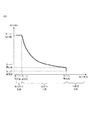
図3は、イオンポンプの装置内の真空度と、高電圧発生回路1の出力電圧―負荷電流特性について示している。
イオンポンプの装置内の真空度を中真空状態で稼動させた場合、高電圧発生回路1の出力に接続された陽極と陰極間の負荷が大きく、大きな負荷電流が流れる。電圧供給部101の印加電圧とパルス供給部113から出力されるパルスの幅に比例してトランス102の1次側の巻線に流れる電流が増加するため、パルス幅が十分に長いと、トランス102が磁気飽和を起こして1次側の巻線に大電流が流れ、高電圧発生回路1が破損する可能性がある。
高電圧発生回路1の破損を防ぐためには、出力電圧―負荷電流特性において中真空状態と高真空状態の境界となる電流値を第一の電流値とすると、電流検出部108から出力された負荷電流値が第一の電流値を下回った状態になるように電流制限をかける必要がある。
イオンポンプの容器内の真空度を中真空状態から高真空状態に遷移させる場合、電圧供給部101から出力される所定のDC電圧と、パルス供給部113から出力される所定のパルスでスイッチング素子104をスイッチングすることにより、出力電圧-負荷電流特性を中真空状態から高真空状態へ遷移させる。真空状態を遷移させている状態では、真空度が向上するほど負荷電流が低下して出力電圧が上昇する。
そこで、中真空状態と高真空状態の境界となる電圧値を第一の電圧値とすると、制御部112は、電圧検出部107と電流検出部108からそれぞれ出力された出力電圧値と負荷電流値を乗算して得た検出電力が、第一の電圧値と第一の電流値を乗算して得た電力を下回った状態になるように電力制限をかけることにより、出力電圧の上昇を抑えることができる。
さらに、真空度を高真空状態から超高真空状態へ遷移させる場合には、電圧供給部101から出力される所定のDC電圧と、パルス供給部113から出力される所定のパルスでスイッチング素子104を長時間スイッチングすることにより、出力電圧-負荷電流特性を、高真空状態から超高真空状態へ遷移させる。
この遷移状態においても、真空度が向上するほど負荷電流が低下して出力電圧が上昇する。10-8Pa程度の超高真空を維持するのに必要な出力電圧が5kVであるのに対して、更に真空度が向上すると出力電圧も更に上昇するため、不要な高電圧が排気機構部114に印加されていることになる。
そこで、真空度が高真空状態と超高真空状態の境界となる電圧値と電流値をそれぞれ第二の電圧値と第二の電流値とすると、制御部112は、電圧検出部107から出力された出力電圧値が第二の電圧値を超え、電流検出部108から出力された負荷電流値が第二の電流値を下回った時点で、電圧制限および高電圧を安定化させることにより、排気機構部114への不要な高電圧の印加を避けることができる。
なお、本実施例では一例として、第一の電圧値、電流値と第二の電圧値、電流値をそれぞれ高真空状態と中真空状態の境界、超高真空状態と高真空状態の境界となる電圧値、電流値に設定したが、それに限定されるものではなく、出力電圧―負荷電流特性に基づき、真空度の遷移状態に応じて設定される。
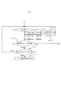
図4および図5に、イオンポンプの容器内の真空度を中真空状態から超高真空状態へ状態遷移させる処理を説明するフローチャートを示す。
高電圧発生回路1をON(A101)した後、ユーザが電子顕微鏡等の装置が備えるユーザインターフェース(図示なし)のボタンを押下する等により真空度最大への遷移を指示すると(A102)、制御部112は、パルス供給部113から出力されるパルスの幅を上限値に設定する(A103)。
電圧供給部101から出力される所定のDC電圧と、パルス供給部113から出力されるパルス幅が上限値に設定されたパルスと、でスイッチング素子104がスイッチングされ、排気機構部114に高電圧が印加される。
排気機構部114に高電圧が印加されてから一定時間が経過した後、制御部112は、電圧検出部107と電流検出部108からそれぞれ出力電圧値と負荷電流値を取得し、負荷電流値と第一の電流値を比較する(A104)。
負荷電流値が第一の電流値を上回った場合には過電流保護のため、制御部112は、パルス供給部113からのパルス出力を止め(A105)、ユーザに真空度が低すぎる旨を知らせるエラーメッセージを表示する(A106)。
一方、負荷電流値が第一の電流値を下回った場合には、制御部は出力電圧値と第一の電圧値を比較する(A107)。出力電圧値が第一の電圧値を上回っていなければ、一定時間が経過した後、制御部112は処理A104に戻る。出力電圧値が第一の電圧値を上回っていれば、制御部112は中真空状態から高真空状態へ遷移したと判断し、出力電圧値と負荷電流値を乗算して得た検出電力と、第一の電圧値と第一の電流値を乗算して得た第一の電力値とを比較する(A108)。
検出電力が第一の電力値を上回った場合には、制御部112は、電力制限をかけるため、パルス幅を縮小し(A109)、一定時間が経過した後に処理A108に戻る。検出電力が第一の電力値を下回った場合には、制御部112は出力電圧値と第二の電圧値の比較、および負荷電流値と第二の電流値の比較を行う(A110)。出力電圧値が第二の電圧値を上回り、かつ負荷電流値が第二の電流値を下回った場合、制御部112は、高真空状態から超高真空状態へ遷移したと判断し、パルス幅を縮小する(A111)。
上記以外の場合、制御部112は、高真空状態が継続していると判断し、一定時間が経過した後に処理A108に戻る。
超高真空状態では、電圧制限および高圧を安定化させるため、出力電圧値と第二の電圧値を等しくする。
制御部112は、出力電圧値と第二の電圧値を比較し(A112)、出力電圧値が第二の電圧値を下回った場合、パルス幅を拡大し(A113)、一定時間が経過した後に処理A112に戻る。
出力電圧値が第二の電圧値を上回った場合、制御部112は、パルス幅を縮小し(A114)、一定時間が経過した後に処理A112に戻る。
出力電圧値と第二の電圧値が等しくなった場合、制御部112は負荷電流値と第二の電流値を比較して(A115)、負荷電流値が第二の電流値を上回った場合には、制御部112は、何らかの要因で超高真空状態から高真空状態へ遷移したと判断し、一定時間が経過した後に処理A108に戻り、負荷電流値が第二の電流値を下回った場合には、制御部112は負荷電流値と第三の電流値を比較する(A116)。
なお、第三の電流値とは、超高真空状態において特に真空度が高い状態であるときの電流値である。
負荷電流値が第三の電流値を上回った場合、制御部112は真空度最大になっていないと判断し、一定時間が経過した後に処理A112に戻る。一方、負荷電流値が第三の電流値を下回った場合、制御部112は真空度が最大になったと判断し、パルス幅の制御を終了して一定のパルス幅で高電圧を印加し続ける。また、ユーザへ真空度が最大となった旨のメッセージを表示する(A117)。
本実施例により、中真空状態から超高真空状態へ遷移させる際に、真空度が低く、負荷電流が規定値を超えた場合には規定の電流値となるように電流制限をかけ、真空度が高く、印加電圧が規定値を超えた場合には規定の電圧値で安定化させることにより、イオンポンプの低消費電力化が可能となる。また電源容量の小さいトランスが使用可能となり、電離用電源装置が小型化する。
なお、極高真空状態および超高真空状態では、制御部112がパルス供給部113から出力されるパルスの幅を上限値に設定した(A103)場合であっても、負荷電流は小さく、トランス102が磁気飽和を起こす可能性はほとんどないが、中真空状態では負荷電流は大きく、磁気飽和を起こして高電圧発生回路1を破損させる可能性がある。
そのため、制御部112は、処理A102と処理A103の間にパルス供給部113から出力されるパルスの幅を下限値に設定し、電圧検出部107と電流検出部108からそれぞれ出力電圧値と負荷電流値を取得して装置内の真空状態が極高真空状態、超高真空状態、高真空状態あるいは中真空状態のいずれかであるか判定を行い、判定結果が高真空状態と中真空状態の境界および高真空状態である場合にパルスの幅を上限値に設定することで、高電圧発生回路1の破損を抑制できる。
また、本実施例では、各種ある昇圧方式の一つである擬似共振フライバック方式を用いて、トランス2次側の電圧検出結果と電流検出結果から装置内の真空度の状態遷移に応じて1次側トランスをスイッチング制御するパルス幅またはパルス周期を調整することを特徴とする高電圧発生回路について説明をしたが、昇圧方式をプシュプル方式、ハーフブリッジ方式、フルブリッジ方式といった他の昇圧方式を用いても本実施例と同様の効果を得ることができ、擬似共振フライバック方式に限定されるものではない。
また、本実施例では真空度を中真空状態から超高真空状態へ遷移させる処理を説明したが、例えば、電子顕微鏡内に試料を入れ替える際に、超高真空状態から中真空状態へ遷移させる処理も考えられる。
超高真空状態から中真空状態へ遷移させる場合、排気機構部114の陽極端子123に印加される出力電圧は、電圧供給部101の出力電圧と、パルス供給部113が出力するパルス幅またはパルス周期で調整することができる。
例えば、制御部112は、電圧供給部101で粗い出力電圧制御を行い、パルス供給部113で詳細な出力電圧制御を行うと良い。またその逆として、制御部112は、パルス供給部113で粗い出力電圧制御を行い、電圧供給部101で詳細な出力電圧制御を行うと良い。
本実施例では、実施例1で示したように、擬似共振フライバック方式を用いてトランス102の2次側の電圧検出結果と電流検出結果から装置内の真空度の状態遷移に応じてトランス102の1次側をスイッチング制御するパルス幅またはパルス周期を調整することに加えて、トランス102の1次側に電圧を供給する電圧供給部101の出力電圧値および出力期間を調整することを特徴とする高電圧発生回路について説明する。
本実施例における高電圧発生回路では、例えば、図1に示す制御部112と電圧供給部101の間を制御信号線で接続する構成により電圧供給部102の出力電圧値および出力期間の調整を実現できる。よって、以降の高圧発生回路の動作の説明においては、図1の符号を用いて説明する。
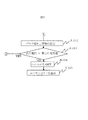
図6および図7に、イオンポンプの容器内の真空度を超高真空状態から中真空状態へ状態遷移させる処理を説明するフローチャートを示す。
高電圧発生回路の電源をON(A201)した後、ユーザが、電子顕微鏡等の装置が備えるユーザインターフェース(図示なし)のボタンを押下する等により、真空度最小への遷移を指示すると(A202)、制御部112は、トランス1次側の電圧供給部101を間欠動作させて出力期間を調整する(A203)。
続いて制御部112はパルス供給部113から出力されるパルスの幅を下限値に設定する(A204)。なお、パルス幅の下限値はユーザ自身で入力する構成でも良い。
電圧供給部101から出力される所定のDC電圧と、パルス供給部113から出力されるパルス幅が下限値に設定されたパルスでスイッチング素子104がスイッチングされて排気機構部114の陽極端子123に高電圧が印加される。
排気機構部114に高電圧が印加されて一定時間が経過した後、制御部112は、電圧検出部107と電流検出部108からそれぞれ出力電圧値と負荷電流値を取得し、取得した負荷電流値と第一の電流値を比較する(A205)。
負荷電流値が第一の電流値を上回った場合、制御部112は、真空度が最小になったと判断し、パルス供給部113からのパルス出力を止めて(A206)、ユーザに真空度が最小となった旨のメッセージを表示する(A207)。
一方、負荷電流値が第一の電流値を下回った場合には、制御部112は、出力電圧値と第一の電圧値を比較する(A208)。出力電圧値が第一の電圧値を上回った場合、制御部112は、真空度が最小になっていないと判断して一定時間が経過した後、処理(A205)に戻る。出力電圧値が第一の電圧値を下回った場合、制御部112は、出力電圧値と負荷電流値を乗算して得た検出電力と、第一の電圧値と第一の電流値を乗算して得た第一の電力値を比較する(A209)。
検出電力が第一の電力値を上回った場合、制御部112は、真空度が最小になっていないと判断して一定時間が経過した後、処理A205に戻る。検出電力が第一の電力値を下回った場合、制御部112は、排気機構部114の陽極と陰極との間で放電が継続していることを確認するため、放電に最低限必要な電圧である第三の電圧値と出力電圧値を比較する(A210)。出力電圧値が第三の電圧値を上回った場合、制御部112は、放電が継続されていると判断して一定時間が経過した後、処理A205に戻る。
一方、出力電圧値が第三の電圧値を下回った場合、制御部112は、放電が停止していると判断してトランス1次側の電圧供給部101の間欠動作を停止して、一定の電圧値を出力するようにさせ(A211)、パルス供給部113から出力されるパルスの幅を上限値に設定する(A212)。一定時間が経過した後、制御部112は電圧検出部から取得した出力電圧値と第三の電圧を比較する(A213)。
出力電圧値が第三の電圧値を上回った場合、制御部112は、放電が開始されたと判断して一定時間が経過した後、処理(A203)に戻る。一方、出力電圧値が第三の電圧値を下回った場合、制御部112は放電が開始されないと判断して、パルス供給部113から出力されるパルスを止めて(A214)、ユーザに放電が開始されない旨を知らせるエラーメッセージを表示する(A215)。
本実施例により、高真空から低真空へ状態遷移させる際に、1次側トランスに電圧を供給する電圧供給部101を間欠動作させて、定期的に装置内の真空度を観測することにより、所定の真空度に達したことを早期にユーザへ知らせることができる。また装置内で放電が発生しない等の異常を早期にユーザへ知らせることができる。
制御部112は、間欠動作周期、パルス幅およびパルス周期、出力電圧値、負荷電流値、観測時間から単位時間あたりの負荷電流値の変化量を算出し、所定の真空度に達するまでの時間を予測できるようにすることで、ユーザにとって装置の使い勝手が向上する。
また、本実施例では真空度を超高真空状態から中真空状態へ遷移させる処理を説明したが、実施例1と同様に中真空状態から超高真空状態へ遷移させる処理も考えられる。中真空状態から超高真空状態へ遷移させる場合、排気機構部114の陽極端子123に印加される出力電圧は、電圧供給部101の出力電圧と、パルス供給部113が出力するパルス幅またはパルス周期で調整することができる。
例えば、制御部112は、電圧供給部101で粗い出力電圧制御を行い、パルス供給部113で詳細な出力電圧制御を行うと良い。またその逆として、制御部112は、パルス供給部113で粗い出力電圧制御を行い、電圧供給部101で詳細な出力電圧制御を行うことで、トランスの製造ばらつき、温度変化等による特性変化を補償することが出来る。
本実施例では、実施例1で示したように、擬似共振フライバック方式を用いてトランス102の2次側の電圧検出結果と電流検出結果から装置内の真空度の状態遷移に応じてトランス102の1次側をスイッチング制御するパルス幅またはパルス周期を調整することに加えて、高真空状態で低消費電力化することを特徴とする高電圧発生回路について説明する。
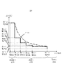
図8に、高真空状態で低消費電力化する高電圧発生回路の出力電圧―負荷電流特性(実線)を示す。破線(F101)は、図3の高真空状態における出力電圧―負荷電流特性である。
高真空状態は、日本工業規格(JIS)にて10-5Pa以上10-1Pa以下と定義されている。また、負荷電流は装置内の圧力に比例するため、負荷電流に閾値を設定する。例えば、装置内の圧力が10-1Pa、10-2Pa、10-3Pa、10-4Pa、10-5Paであるときの負荷電流の閾値をそれぞれ第一の電流値、第四の電流値、第五の電流値、第六の電流値、第二の電流値とする。
一方、低消費電力化するため、出力電圧と負荷電流の積が所定の電力となるように、出力電圧の閾値を設定する。例えば第四の電流値で所定の電力となる第四の電圧値、第五の電流値で所定の電力となる第五の電圧値、第六の電流値で所定の電力となる第六の電圧値とする。
本実施例におけるイオンポンプの容器内の真空度を超高真空状態から中真空状態へ状態遷移させる処理は、以下の通りである。
装置内の真空度が上昇して第一の電流値を下回り、中真空状態から高真空状態へ遷移した時点で、制御部112は出力電圧が第一の電圧値を維持するように高電圧を安定化させる。さらに真空度が上昇して第四の電流値を下回った時点で、制御部112は負荷電流が第四の電流値になるように電流を安定化させる。
続いて出力電圧が第四の電圧値を上回った時点で、制御部112は出力電圧が第四の電圧値を維持するように高電圧を安定化させる。更に真空度が上昇して第五の電流値を下回った時点で制御部112は負荷電流が第五の電流値になるように電流を安定化させる。
続いて出力電圧が第五の電圧値を上回った時点で、制御部112は出力電圧が第五の電圧値を維持するように高電圧を安定化させる。更に真空度が上昇して第六の電流値を下回った時点で制御部112は負荷電流が第六の電流値になるように電流を安定化させる。
続いて出力電圧が第六の電圧値を上回った時点で、制御部112は出力電圧が第六の電圧値を維持するように高電圧を安定化させる。更に真空度が上昇して第六の電流値を下回った時点で制御部112は、高真空状態から超高真空状態へ遷移したと判断し、負荷電流が第二の電流値になるように電流を安定化させる。
続いて出力電圧が第二の電圧値を上回った時点で、制御部112は出力電圧が第二の電圧値を維持するように高電圧を安定化させる。
本実施例により、高真空状態において、容器内の圧力に応じて負荷電流と出力電圧の閾値を設定し、負荷電流、出力電圧を検出して電圧値、電流値を制御することで、装置の低消費電力化が可能となる。
なお、本発明は上記した実施例に限定されるものではなく、様々な変形例が含まれる。例えば、上記した実施例は本発明を分かりやすく説明するために詳細に説明したものであり、必ずしも説明した全ての構成を備えるものに限定されるものではない。また、ある実施例の構成の一部を他の実施例の構成に置き換えることが可能であり、また、ある実施例の構成に他の実施例の構成を加えることも可能である。また、各実施例の構成の一部について、他の構成の追加・削除・置換をすることが可能である。
また、上記の各構成、機能、処理部、処理手段等は、それらの一部又は全部を、例えば集積回路で設計する等によりハードウェアで実現してもよい。また、上記の各構成、機能等は、プロセッサがそれぞれの機能を実現するプログラムを解釈し、実行することによりソフトウェアで実現してもよい。各機能を実現するプログラム、テーブル、ファイル等の情報は、メモリや、ハードディスク、SSD(Solid State Drive)等の記録装置、または、ICカード、SDカード、DVD等の記録媒体に置くことができる。
また、制御線や情報線は説明上必要と考えられるものを示しており、製品上必ずしも全ての制御線や情報線を示しているとは限らない。実際には殆ど全ての構成が相互に接続されていると考えてもよい。
また、制御線や情報線は説明上必要と考えられるものを示しており、製品上必ずしも全ての制御線や情報線を示しているとは限らない。実際には殆ど全ての構成が相互に接続されていると考えてもよい。
1 高電圧発生回路
2 イオンポンプ
20 電子顕微鏡の真空容器
21 商用AC電源
22 AC-DC変換部
101 電圧供給部
102 トランス
103 1次側のコンデンサ
104 スイッチング素子
105 2次側の整流用ダイオード
106 2次側の整流用コンデンサ
107 電圧検出部
108 電流検出部
109、110、111 抵抗
112 制御部
113 パルス供給部
114 排気機構部
115 入力部
116 出力部
2 イオンポンプ
20 電子顕微鏡の真空容器
21 商用AC電源
22 AC-DC変換部
101 電圧供給部
102 トランス
103 1次側のコンデンサ
104 スイッチング素子
105 2次側の整流用ダイオード
106 2次側の整流用コンデンサ
107 電圧検出部
108 電流検出部
109、110、111 抵抗
112 制御部
113 パルス供給部
114 排気機構部
115 入力部
116 出力部
Claims (16)
- 排気機構部が有する陰極と陽極に電圧を印加することで容器内を真空にするイオンポンプであって、
トランス1次側に直流電圧を供給する電圧供給部と、
トランス1次側のスイッチング素子に電圧パルスを供給するパルス供給部と、
トランス2次側の出力電圧を検出する電圧検出部と、
トランス2次側の負荷電流を検出する電流検出部と、
前記検出した出力電圧と、負荷電流と、前記検出した出力電圧値と負荷電流を乗算して算出した出力電力値のうち少なくともいずれか一つに基づいて、前記パルス供給部が出力する電圧パルスのパルス幅またはパルス周期を調整する制御部と、
を備えるイオンポンプ。 - 請求項1に記載のイオンポンプであって、
前記制御部は、前記検出した負荷電流と所定電流値を比較し、
前記負荷電流が前記所定電流値よりも大きい場合、前記パルス幅を縮小する、
という制御状態を有することを特徴とするイオンポンプ。 - 請求項2に記載のイオンポンプであって、
前記所定電流値とは、前記容器内の真空度が中真空状態と高真空状態の境界となる第一の電流値であることを特徴とするイオンポンプ。 - 請求項3に記載のイオンポンプであって、
前記容器内の真空度が中真空状態と高真空状態の境界となる電圧値を第一の電圧値とすると、
前記制御部は、前記負荷電流が前記第一の電流値よりも小さい場合、前記出力電圧と前記第一の電圧値を比較し、
前記出力電圧が前記第一の電圧値よりも大きい場合、前記出力電力値と、前記第一の電圧値と前記第一の電流値を乗算して算出した第一の電力値と、を比較し、
前記出力電力値が前記第一の電力値よりも大きい場合、前記パルス幅を縮小する、
という制御状態を有することを特徴とするイオンポンプ。 - 請求項4に記載のイオンポンプであって、
前記容器内の真空度が高真空状態と超高真空状態の境界となる電流値および電圧値をそれぞれ第二の電流値、第二の電圧値とすると、
前記出力電力値が前記第一の電力値よりも大きい場合、前記出力電圧と前記第二の電圧値とを比較し、
前記出力電圧が前記第二の電圧値より大きい場合、前記パルス幅を縮小する、
という制御状態を有することを特徴とするイオンポンプ。 - 請求項5に記載のイオンポンプであって、
前記制御部は、前記出力電圧と前記第二の電圧値とを比較し、
前記出力電圧が前記第二の電圧値よりも小さい場合、前記パルス幅を拡大し、
前記出力電圧が前記第二の電圧値より大きい場合、前記パルス幅を縮小する、
という制御状態を有すること特徴とするイオンポンプ。 - 請求項6に記載のイオンポンプであって、
前記容器内の真空度が超高真空状態より高くなる電流値を第三の電流値とすると、
前記制御部は、前記出力電圧と前記第二の電圧値が等しい場合、前記負荷電流と前記第二の電流値を比較し、
前記負荷電流が前記第二の電流値より小さい場合、前記負荷電流と前記第三の電流値を比較し、
前記負荷電流が前記第三の電流値よりも小さい場合、パルス幅の制御を終了する、
という制御状態を有することを特徴とするイオンポンプ。 - 請求項1に記載のイオンポンプであって、
前記制御部は、前記検出した出力電圧と、負荷電流と、前記検出した出力電圧値と負荷電流を乗算して算出した出力電力値のうち少なくともいずれか一つに基づいて、前記電圧供給部が出力する電圧を調整することを特徴とするイオンポンプ。 - 請求項8に記載のイオンポンプであって、
前記制御部は、前記電圧供給部を間欠動作させることで前記電圧供給部が出力する電圧の出力期間を調整することを特徴とするイオンポンプ。 - 請求項9に記載のイオンポンプであって、
前記制御部は、前記検出した負荷電流と所定電流値を比較し、
前記負荷電流が前記所定電流値よりも大きい場合、前記パルス幅を縮小する、
という制御状態を有することを特徴とするイオンポンプ。 - 請求項10に記載のイオンポンプであって、
前記所定電流値とは、前記容器内の真空度が中真空状態と高真空状態の境界となる第一の電流値であることを特徴とするイオンポンプ。 - 請求項11に記載のイオンポンプであって、
前記容器内の真空度が中真空状態と高真空状態の境界となる電圧値を第一の電圧値、前記排気機構部の陽極と陰極との間の放電に最低限必要な電圧値を第三の電圧値、とすると、
前記制御部は、前記負荷電流が前記第一の電流値よりも小さい場合、前記出力電圧と前記第一の電圧値を比較し、
前記出力電圧が前記第一の電圧値よりも小さい場合、前記出力電力値と、前記第一の電圧値と前記第一の電流値を乗算して算出した第一の電力値と、を比較し、
前記出力電力値が前記第一の電力値よりも小さい場合、前記出力電圧と前記第三の電圧値を比較し、
前記出力電圧が前記第三の電圧値より小さい場合、前記電圧供給部の間欠動作を停止させ、一定の電圧値を出力させる、
という制御状態を有することを特徴とするイオンポンプ。 - 請求項12に記載のイオンポンプであって、
前記電圧供給部が一定の電圧値を出力しているとき、前記出力電圧と前記第三の電圧値を比較し、前記出力電圧が前記第三の電圧値より小さい場合、
前記制御部は、前記パルス供給部に前記電圧パルスの出力を停止させることを特徴とするイオンポンプ。 - 請求項1に記載のイオンポンプであって、
前記容器内の真空度が、中真空状態と高真空状態の境界となる電流値および電圧値をそれぞれ第一の電流値、第一の電圧値と、高真空状態と超高真空状態の境界となる電流値および電圧値をそれぞれ第二の電流値、第二の電圧値と、すると、
前記制御部は、前記検出した負荷電流と前記第一の電流値とを比較し、
前記負荷電流値が前記第一の電流値より小さい場合、前記出力電圧を前記第一の電圧値となるようにし、
前記負荷電流が第二の電流値より小さい場合、前記負荷電流を前記第二の電流値となるようにし、
前記負荷電流が前記第二の電流値のときに、前記出力電圧が前記第二の電圧値より大きい場合、前記出力電圧を前記第二の電圧値となるようする、
という制御状態を有することを特徴とするイオンポンプ。 - トランス1次側に直流電圧を供給する電圧供給部と、
トランス1次側のスイッチング素子に電圧パルスを供給するパルス供給部と、
トランス2次側の出力電圧を検出する電圧検出部と、
トランス2次側の負荷電流を検出する電流検出部と、
前記検出した出力電圧と、負荷電流と、前記検出した出力電圧値と負荷電流を乗算して算出した出力電力値のうち少なくともいずれか一つに基づいて、前記パルス供給部が出力する電圧パルスのパルス幅またはパルス周期を調整する制御部と、
を備える高電圧発生回路。 - 請求項15に記載の高電圧発生回路であって、
前記制御部は、前記検出した出力電圧と、負荷電流と、前記検出した出力電圧値と負荷電流を乗算して算出した出力電力値のうち少なくともいずれか一つに基づいて、前記電圧供給部が出力する電圧を調整することを特徴とする高電圧発生回路。
Applications Claiming Priority (2)
| Application Number | Priority Date | Filing Date | Title |
|---|---|---|---|
| JP2013-234539 | 2013-11-13 | ||
| JP2013234539A JP2015095378A (ja) | 2013-11-13 | 2013-11-13 | 高電圧発生回路およびそれを用いたイオンポンプ |
Publications (1)
| Publication Number | Publication Date |
|---|---|
| WO2015072287A1 true WO2015072287A1 (ja) | 2015-05-21 |
Family
ID=53057229
Family Applications (1)
| Application Number | Title | Priority Date | Filing Date |
|---|---|---|---|
| PCT/JP2014/077772 Ceased WO2015072287A1 (ja) | 2013-11-13 | 2014-10-20 | 高電圧発生回路およびそれを用いたイオンポンプ |
Country Status (2)
| Country | Link |
|---|---|
| JP (1) | JP2015095378A (ja) |
| WO (1) | WO2015072287A1 (ja) |
Cited By (1)
| Publication number | Priority date | Publication date | Assignee | Title |
|---|---|---|---|---|
| CN120545156A (zh) * | 2025-07-25 | 2025-08-26 | 苏州博众仪器科技有限公司 | 一种离子泵电源电路 |
Citations (2)
| Publication number | Priority date | Publication date | Assignee | Title |
|---|---|---|---|---|
| JPH0146884B2 (ja) * | 1979-05-30 | 1989-10-11 | Origin Electric | |
| JP2008061420A (ja) * | 2006-08-31 | 2008-03-13 | Harison Toshiba Lighting Corp | 電源装置及び電源供給システム |
Family Cites Families (5)
| Publication number | Priority date | Publication date | Assignee | Title |
|---|---|---|---|---|
| JPS5854465B2 (ja) * | 1981-06-22 | 1983-12-05 | 東北金属工業株式会社 | イオンポンプ用電源 |
| JPS5925155A (ja) * | 1982-08-03 | 1984-02-09 | Anelva Corp | 真空放電装置用電源 |
| IT1179833B (it) * | 1984-11-28 | 1987-09-16 | Varian Spa | Dispositivo elettronico per l alimentazione di una pompa ionica a due tensioni differenziate e per la misura perfezionata della pressione vigente in detta pompa |
| JPS6354245U (ja) * | 1986-09-26 | 1988-04-12 | ||
| JP2001050845A (ja) * | 1999-08-09 | 2001-02-23 | Shimadzu Corp | 電離用電源装置 |
-
2013
- 2013-11-13 JP JP2013234539A patent/JP2015095378A/ja active Pending
-
2014
- 2014-10-20 WO PCT/JP2014/077772 patent/WO2015072287A1/ja not_active Ceased
Patent Citations (2)
| Publication number | Priority date | Publication date | Assignee | Title |
|---|---|---|---|---|
| JPH0146884B2 (ja) * | 1979-05-30 | 1989-10-11 | Origin Electric | |
| JP2008061420A (ja) * | 2006-08-31 | 2008-03-13 | Harison Toshiba Lighting Corp | 電源装置及び電源供給システム |
Cited By (1)
| Publication number | Priority date | Publication date | Assignee | Title |
|---|---|---|---|---|
| CN120545156A (zh) * | 2025-07-25 | 2025-08-26 | 苏州博众仪器科技有限公司 | 一种离子泵电源电路 |
Also Published As
| Publication number | Publication date |
|---|---|
| JP2015095378A (ja) | 2015-05-18 |
Similar Documents
| Publication | Publication Date | Title |
|---|---|---|
| US9667153B2 (en) | Switching power supply apparatus for generating control signal for lowering switching frequency of switching devices | |
| JP6447095B2 (ja) | スイッチング電源回路 | |
| JP6272691B2 (ja) | 振幅正規化回路、電源装置および電子機器 | |
| JP2006067730A (ja) | 力率改善回路 | |
| JP4963068B2 (ja) | 力率改善回路 | |
| JP5746560B2 (ja) | スイッチング電源装置 | |
| EP3079252A2 (en) | Universal input voltage dc-dc converter employing low voltage capacitor power bank | |
| JP2013251938A (ja) | スイッチング電源及びスイッチング電源を備えた電子機器 | |
| CN101199236A (zh) | 感应加热装置 | |
| WO2023243321A1 (ja) | コンバータ装置 | |
| JP2005287249A (ja) | スイッチング電源装置 | |
| US20150181675A1 (en) | Power factor correction circuit, operating device for a light-emitting means and method for controlling a power factor correction circuit | |
| KR20150137872A (ko) | 전원 공급 장치와 전원 공급 장치의 전력 변환 회로 | |
| JP2018196271A (ja) | 電力変換装置 | |
| JP7109688B2 (ja) | 電力変換装置 | |
| JP2015095378A (ja) | 高電圧発生回路およびそれを用いたイオンポンプ | |
| JP7332395B2 (ja) | 電源回路の制御装置及び制御方法 | |
| JP7825700B2 (ja) | 電力変換方法及び電力変換装置 | |
| JP4764980B2 (ja) | 直流−直流変換装置 | |
| JP2006296158A (ja) | 力率改善回路 | |
| JP2014082156A (ja) | 点灯装置 | |
| CN115995970A (zh) | 高压离子风发生器及其负输出电压控制方法、电路 | |
| JP4893120B2 (ja) | 誘導加熱装置 | |
| JP2017085793A (ja) | 電源装置およびプラズマ処理装置 | |
| JP4887681B2 (ja) | 誘導加熱装置 |
Legal Events
| Date | Code | Title | Description |
|---|---|---|---|
| 121 | Ep: the epo has been informed by wipo that ep was designated in this application |
Ref document number: 14861659 Country of ref document: EP Kind code of ref document: A1 |
|
| NENP | Non-entry into the national phase |
Ref country code: DE |
|
| 122 | Ep: pct application non-entry in european phase |
Ref document number: 14861659 Country of ref document: EP Kind code of ref document: A1 |