WO2015072027A1 - スライドファスナー排出装置 - Google Patents
スライドファスナー排出装置 Download PDFInfo
- Publication number
- WO2015072027A1 WO2015072027A1 PCT/JP2013/081002 JP2013081002W WO2015072027A1 WO 2015072027 A1 WO2015072027 A1 WO 2015072027A1 JP 2013081002 W JP2013081002 W JP 2013081002W WO 2015072027 A1 WO2015072027 A1 WO 2015072027A1
- Authority
- WO
- WIPO (PCT)
- Prior art keywords
- slide fastener
- belt conveyor
- fastener
- gripper
- discharge
- Prior art date
- Legal status (The legal status is an assumption and is not a legal conclusion. Google has not performed a legal analysis and makes no representation as to the accuracy of the status listed.)
- Ceased
Links
Images









Classifications
-
- A—HUMAN NECESSITIES
- A44—HABERDASHERY; JEWELLERY
- A44B—BUTTONS, PINS, BUCKLES, SLIDE FASTENERS, OR THE LIKE
- A44B19/00—Slide fasteners
- A44B19/42—Making by processes not fully provided for in one other class, e.g. B21D53/50, B21F45/18, B22D17/16, B29D5/00
Definitions
- This invention relates to a slide fastener discharging apparatus, and more particularly to a slide fastener discharging apparatus incorporated in a slide fastener assembling apparatus.
- a slide fastener finished in the top stopper mounting device is known to be pulled out from the top stopper mounting device with a pair of left and right grippers and discharged (see, for example, Patent Document 1). .
- the present invention has been made in view of the above-described problems, and an object of the present invention is to provide a slide fastener discharge device that can shorten the time for moving the gripper and can reduce the size of the discharge device. .
- a gripper that moves while gripping the slide fastener, a belt conveyor that is disposed below the gripper and that transfers the slide fastener released from gripping by the gripper, and the slide fastener transported by the belt conveyor to the non-defective product discharge section
- a slide fastener discharging apparatus comprising: a discharging device for discharging.
- the slide fastener discharging apparatus according to (1) further comprising a fastener dropping device that drops the slide fastener released from gripping by the gripper onto a belt conveyor.
- the discharger includes a cylinder and a fastener discharge plate that is attached to the tip of the rod of the cylinder and extends along the transfer direction of the belt conveyor, and the fastener discharge plate moves in the width direction of the belt conveyor as the rod advances and retreats.
- (1) to (3) wherein the slide fastener on the belt conveyor is pushed out of the belt conveyor and dropped to a non-defective product discharge portion by movement of the fastener discharge plate.
- the slide fastener discharging apparatus according to any one of the above.
- the slide fastener discharging apparatus according to any one of (1) to (5), further comprising an inspection device that inspects at least one of a slider and a stopper of the slide fastener.
- the non-defective product discharge portion includes a flap device that holds the slide fastener discharged from the belt conveyor for a certain period of time, and a fastener storage portion that is disposed below the flap device, and the flap device is a pair that opens and closes downward.
- the pair of flaps is set so that it receives a slide fastener discharged from the belt conveyor and opens after a certain period of time, and when the pair of flaps opens, the slide fastener is dropped into the fastener storage section.
- the slide fastener discharging apparatus according to any one of (1) to (7), characterized in that
- a gripper that moves while gripping the slide fastener, a belt conveyor that is disposed below the gripper and that transfers the slide fastener released from gripping by the gripper, and the slide fastener transferred by the belt conveyor are non-defective products. Therefore, the gripper travel distance can be shortened as compared with the case where a long slide fastener is transferred only by the gripper. Thereby, the movement time of a gripper can be shortened and a discharge device can be reduced in size. Furthermore, since the gripper moving time can be shortened, the waiting time on the slide fastener assembling apparatus side can be shortened, and the slide fastener assembling time can be shortened.
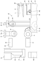
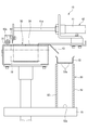
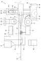
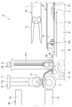
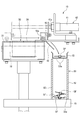
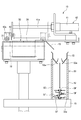
- FIG. 2 is an enlarged side view of the periphery of the inspection device, the roll device, and the fastener removing device shown in FIG. 1. It is an enlarged side view of the periphery of the belt conveyor shown in FIG.
- FIG. 5 is a sectional view taken along line AA in FIG. 4. It is a side view explaining the state where the finished slide fastener was gripped by the gripper. It is a side view explaining the state where a slide fastener is transferred by a gripper and an inspection is performed by an inspection device.
- the upper side is the upper side with respect to the paper surface of FIG. 1
- the lower side is the lower side with respect to the paper surface of FIG. 1
- the front side is with respect to the paper surface of FIG.
- the left side and the rear side are the right side with respect to the paper surface of FIG. 1
- the left side is the back side with respect to the paper surface of FIG. 1
- the right side is the front side with respect to the paper surface of FIG.
- the front side of the slide fastener discharging apparatus is also referred to as the upstream side
- the rear side is also referred to as the downstream side.
- the left-right direction of a slide fastener discharge apparatus is also called the width direction.
- the front side is the front side with respect to the paper surface of FIG. 2
- the back side is the back side with respect to the paper surface of FIG. 2
- the upper side is the upper side with respect to the paper surface of FIG.
- the lower side with respect to the paper surface the left side is the left side with respect to the paper surface of FIG. 2
- the right side is the right side with respect to the paper surface of FIG.
- the left-right direction of a slide fastener is also called the width direction.
- the vertical direction of the slide fastener is also called the length direction.
- the slide fastener discharging apparatus 10 of the present embodiment is incorporated in the slide fastener assembling apparatus, and specifically, as shown in FIG. It has been incorporated.
- symbol L in a figure is the transfer line to which slide fastener SF is transferred by the gripper 20 mentioned later.
- the slide fastener SF includes a pair of left and right fastener tapes T, a pair of left and right fastener element rows E that are respectively sewn to opposing side edges of the pair of left and right fastener tapes T, and a pair of left and right fasteners.
- the slide fastener SF includes a pair of left and right fastener tapes T, a pair of left and right fastener element rows E that are respectively sewn to opposing side edges of the pair of left and right fastener tapes T, and a pair of left and right fasteners.
- the slider S for engaging and separating the fastener element row E
- the upper stopper (stop portion) P1 attached to the upper ends of the pair of left and right fastener element rows E, respectively.
- a bottom stop P2 to be provided.
- the slide fastener discharging apparatus 10 of the present embodiment is a model suitable for discharging a long slide fastener
- the slide fastener SF is assumed to be a long slide fastener having a length of 50 cm or more, for example. ing. Further, the slide fastener discharging apparatus 10 of the present embodiment can discharge even a slide fastener that is not long.
- the slider S slides along the pair of left and right fastener element rows E to engage and separate the pair of left and right fastener element rows E.
- the upper stopper P1 and the lower stopper P2 are for stopping the slider S from sliding.
- the fastener element row E is a coil-like fastener element row in the present embodiment, but is not limited to this, and a zigzag fastener element row, a fastener element row made of synthetic resin injection molding, and a metal It may be a fastener element row.
- the bottom stop may be an opening tool or a reverse opening tool.
- the top stopper mounting device M is disposed below the transfer line L, and is disposed below the transfer line L.
- the horn M1 is disposed below the transfer line L.
- An anvil M2 provided so as to be slidable up and down, and a pressing portion M3 disposed below the transfer line L and pressing the anvil M2 from below.
- the horn M1 and the pressing part M3 are driven up and down by a cylinder (not shown).
- the anvil M2 is driven up and down together with the horn M1.
- the pressing part M3 moves upward, and the anvil M2 is pressed upward and moved upward, so that the top stopper P1 is attached to the fastener tape T.
- the upper stopper P1 is welded to the fastener tape T by the ultrasonic energy of the horn M1, and the slide fastener SF is finished.
- the slide fastener discharging device 10 of the present embodiment includes a gripper 20 that grips and transfers the slide fastener SF finished by the top stopper mounting device M, and a gripper 20.
- a belt conveyor 30 for transferring the slide fastener SF released from gripping by the gripper 20, a discharger 40 for discharging the slide fastener SF transferred by the belt conveyor 30 to the non-defective product discharge section 50, and a belt conveyor 30 is disposed on the upper surface of the upstream end of the belt 30 and drops the slide fastener SF released from gripping by the gripper 20 onto the belt conveyor 30.
- the fastener removing device 60 is disposed on the upstream side of the fastener removing device 60 and is dropped onto the belt conveyor 30.
- a roll device 70 to be transferred an inspection device 80 which is arranged upstream of the roll device 70 and inspects the slider S and the top stopper P1 of the slide fastener SF, and a pail which is arranged below the downstream end of the belt conveyor 30.
- a defective defective product discharge section 90 is arranged
- the gripper 20 grips the downstream end portion of the slide fastener SF finished by the upper stopper attaching device M and transfers the slide fastener SF to a predetermined position of the belt conveyor 30. And a pair of upper and lower grippers 21 that grip the left and right fastener tapes T of the slide fastener SF, and a moving device (not shown) that moves the pair of upper and lower grippers 21 in the upstream and downstream directions.
- the belt conveyor 30 includes a gantry 31, a driving roller 32 disposed at the upstream end of the gantry 31, a driven roller 33 disposed at the downstream end of the gantry 31, And a belt 34 wound around the driven rollers 32 and 33.
- first to third passage detection sensors 35a to 35c for detecting passage of the transferred slide fastener SF are provided on the upper surface of the gantry 31.
- a shutter device 36 is provided between the second and third passage detection sensors 35b and 35c on the upper surface of the gantry 31 to prevent the slide fastener SF from being transferred further downstream.
- the first passage detection sensor 35a detects the passage of a good slide fastener SF and reduces the transfer speed of the belt conveyor 30.
- the second passage detection sensor 35b detects passage of a non-defective slide fastener SF, stops the belt conveyor 30, and stops the slide fastener SF at a predetermined position.
- the third passage detection sensor 35c detects passage of a defective slide fastener SF. Note that the inspection device 80 determines whether the slide fastener SF is non-defective or defective.
- the shutter device 36 includes a cylinder 37 and a stop plate 38 having an L-shaped cross section that is attached to the tip of the rod 37a of the cylinder 37.
- the stop plate is moved forward and backward by the rod 37a. 38 is configured to move up and down.
- the stop plate 38 is moved downward when the belt conveyor 30 is transferring the non-defective slide fastener SF (see FIG. 11), and is stopped when the belt conveyor 30 is transferring the defective slide fastener SF. Is moved (see FIG. 15).
- the discharger 40 is attached to the tip of the cylinder 41 and the rod 41 a of the cylinder 41 and has an L-shaped fastener discharge plate 42 extending along the transfer direction of the belt conveyor 30.
- the fastener discharge plate 42 is configured to move along the width direction of the belt conveyor 30 as the rod 41a advances and retreats. Further, the fastener discharge plate 42 is provided with a pair of guide rollers 42 a that roll on the belt 34 of the belt conveyor 30 and guide the movement of the fastener discharge plate 42 in the width direction.
- the rod 41a of the cylinder 41 is retracted, and the fastener discharge plate 42 is moved to the cylinder 41 side (right side in the figure).
- the non-defective slide fastener SF is pushed out of the belt conveyor 30 and dropped onto the non-defective product discharge section 50.
- a plate-like slope portion 43 that gently drops the slide fastener SF pushed out by the fastener discharge plate 42 onto the non-defective product discharge portion 50 is provided on the upper surface of the belt conveyor 30 on the cylinder 41 side. It is provided along.
- the fastener discharge plate 42 is moved to the right side of the drawing, and the non-defective slide fastener SF is dropped on the non-defective product discharge portion 50 arranged on the right side of the drawing.
- the present invention is not limited to this, and the fastener discharge plate 42 may be moved to the left side of the drawing to drop the non-defective slide fastener SF onto the non-defective product discharge portion 50 disposed on the left side of the drawing.
- the non-defective product discharge unit 50 includes a gantry 51 disposed below the gantry 31 of the belt conveyor 30, and a pair of plate members 52 disposed below the distal end portion of the slope portion 43 on the gantry 51. And a flap device 53 that is disposed above the pair of plate members 52 and holds the slide fastener SF dropped from the belt conveyor 30 for a certain period of time.
- a space between the pair of plate members 52 serves as a fastener storage portion 52 a that stores a predetermined number of slide fasteners SF, and the fastener storage portion 52 a is disposed below the flap device 53.
- the flap device 53 has a pair of flaps 53a that open and close downward.
- the pair of flaps 53a are closed when the slide fastener SF is dropped from the belt conveyor 30, as shown in FIGS.
- the slide fastener SF is received and set to open after a predetermined time. Then, by holding the slide fastener SF once by the flap device 53, the posture of the slide fastener SF when being dropped into the fastener storage portion 52a is made constant, and the plurality of slide fasteners SF in the fastener storage portion 52a is well organized. Become.
- the fastener dropping device 60 includes a cylinder 61 and a roller 62 attached to the tip of the rod 61a of the cylinder 61, and is configured such that the roller 62 moves up and down as the rod 61a moves forward and backward. ing.
- the roller 62 is moved down after the gripper 20 releases the grip of the slide fastener SF, and the slide fastener SF is dropped onto the belt conveyor 30 by the lowered roller 62 (see FIG. 9). . Furthermore, the roller 62 that has been moved down guides the transfer of the slide fastener SF to the downstream side by the belt conveyor 30 and the roll device 70 in the lowered state (see FIG. 10). The roller 62 is moved up after guiding the transfer of the slide fastener SF.
- the roll device 70 includes a drive roller 71 disposed below the transfer line L and a guide roller 72 disposed above the transfer line L.
- the guide roller 72 is attached to the tip of the rod 73a of the cylinder 73, and is configured to move up and down as the rod 73a advances and retreats.
- the slide fastener SF is sandwiched between the drive roller 71 and the guide roller 72, and when the drive roller 71 rotates, the slide fastener SF is transferred downstream (FIG. 10). reference).
- the drive roller 71 is set to rotate in synchronization with the belt conveyor 30.
- a substantially arcuate guide plate 74 is provided between the belt conveyor 30 and the roll device 70 to guide the transfer of the slide fastener SF by the belt conveyor 30 and the roll device 70.
- the inspection device 80 includes an inspection camera 81 disposed below the transfer line L, and an illumination device 82 disposed above the transfer line L, and is attached to the slide fastener SF.
- the presence / absence of the slider S and the upper stopper P1 and the mounting position of the upper stopper P1 are inspected by an image taken by the inspection camera 81. Then, the inspection by the inspection device 80 is performed while the gripper 20 transfers the slide fastener SF to the downstream side, as shown in FIG.
- the downstream end of the slide fastener SF finished by the top stopper attaching device M is gripped by the gripper 20.
- the slide fastener SF is transferred to the downstream side by the gripper 20, and the slider S and the top stopper P1 of the slide fastener SF are inspected by the inspection device 80.
- the transfer of the slide fastener SF by the gripper 20 is stopped, and the slide fastener SF is arranged at a predetermined position.
- the gripper 20 releases the grip of the slide fastener SF, and the roller 62 of the fastener removing device 60 is moved downward, so that the slide fastener SF is dropped onto the belt 34 of the belt conveyor 30. It is.
- the belt conveyor 30 and the drive roller 71 of the roll device 70 are rotated and the guide roller 72 of the roll device 70 is moved downward, so that the slide fastener SF is transferred to the downstream side.
- the stop plate 38 of the shutter device 36 is moved down, and the first and second passage detection sensors 35a and 35b.
- the transfer of the slide fastener SF by the belt conveyor 30 is stopped, and the slide fastener SF is arranged at a predetermined position.
- the slide fastener SF is gripped by the gripper 20 in the top stopper attaching apparatus M, and the slide fastener SF is transferred to a predetermined position on the belt conveyor 30 by the gripper 20.
- the first transfer step until the gripper 20 is released from the gripper 20 (see FIGS. 6 to 9), and the released slide fastener SF is dropped onto the belt conveyor 30 by the fastener dropping device 60.
- the moving distance of the gripper 20 is shortened, the moving time of the gripper 20 can be shortened. Therefore, since the waiting time on the slide fastener assembling apparatus side can be shortened, the assembly time of the slide fastener SF can be shortened. Further, by shortening the moving distance of the gripper 20, it is possible to reduce a rail for moving the gripper 20, a case surrounding the moving area of the gripper 20, and the like, so that the discharge device 10 can be downsized.
- the stop plate 38 of the shutter device 36 is maintained in the upward movement state as shown in FIG.
- the fastener SF is transferred to the defective product discharge unit 90 and dropped into the defective product discharge unit 90.
- the passage of the defective slide fastener SF is detected by the third passage detection sensor 35c, and the rotation of the belt conveyor 30 is stopped based on this detection signal.
- the gripper 20 that moves while gripping the slide fastener SF, and the slide fastener that is disposed below the gripper 20 and released from gripping by the gripper 20 are released.
- the belt conveyor 30 for transferring SF and a discharger 40 for discharging the slide fastener SF transferred by the belt conveyor 30 to the non-defective product discharge portion 50 are provided.
- the moving distance of the gripper 20 can be shortened.
- the movement time of the gripper 20 can be shortened and the discharge device 10 can be reduced in size.
- the movement time of the gripper 20 can be shortened, the waiting time on the slide fastener assembling apparatus side can be shortened, and the assembly time of the slide fastener SF can be shortened.
- the slide fastener SF is provided on the belt conveyor 30 because the slide fastener SF is dropped on the belt conveyor 30 after the grip fastener 20 has been released. Can be dropped.
- the roll device 70 for transferring the slide fastener SF in cooperation with the belt conveyor 30 since the roll device 70 for transferring the slide fastener SF in cooperation with the belt conveyor 30 is provided, the long slide fastener SF can be efficiently and reliably secured to the belt conveyor 30. Can be transferred to.
- the fastener discharge plate 42 is configured to move along the width direction of the belt conveyor 30 by the advancement and retreat of the rod 41a of the cylinder 41, and the movement of the fastener discharge plate 42 is performed.
- the slide fastener SF on the belt conveyor 30 is pushed out of the belt conveyor 30 and dropped onto the non-defective product discharge section 50, so that the long slide fastener SF can be reliably dropped onto the non-defective product discharge section 50.
- the fastener discharge plate 42 is provided with a pair of guide rollers 42a that roll on the belt conveyor 30 and guide the movement of the fastener discharge plate 42 in the width direction.
- the fastener discharge plate 42 can be moved smoothly in the width direction.
- the inspection device 80 for inspecting the slider S and the top stopper P1 of the slide fastener SF since the inspection device 80 for inspecting the slider S and the top stopper P1 of the slide fastener SF is provided, the inspection by the operator's visual inspection becomes unnecessary. For this reason, since an operation man-hour can be decreased, the manufacturing cost of slide fastener SF can be reduced.
- the non-defective product discharging unit 50 includes the flap device 53 that holds the slide fastener SF dropped from the belt conveyor 30 for a certain period of time.
- the postures of the slide fasteners SF can be made constant, whereby the plurality of slide fasteners SF in the fastener storage portion 52a can be well organized.
- this invention is not limited to what was illustrated to the said embodiment, In the range which does not deviate from the summary of this invention, it can change suitably.
- the shutter device, the fastener removing device, the roll device, and the inspection device are provided.
- the present invention is not limited thereto, and these may not be provided.
Landscapes
- Slide Fasteners (AREA)
Abstract
Description
(1)スライドファスナーを把持しながら移送するグリッパと、グリッパの下方に配置され、グリッパによる把持が解除されたスライドファスナーを移送するベルトコンベアと、ベルトコンベアにより移送されたスライドファスナーを良品排出部に排出する排出機と、を備えることを特徴とするスライドファスナー排出装置。
(2)グリッパによる把持が解除されたスライドファスナーをベルトコンベアに落とすファスナー落し装置を備えることを特徴とする(1)に記載のスライドファスナー排出装置。
(3)スライドファスナーをベルトコンベアと協働して移送するロール装置を備えることを特徴とする(1)又は(2)に記載のスライドファスナー排出装置。
(4)排出機は、シリンダと、シリンダのロッドの先端部に取り付けられ、ベルトコンベアの移送方向に沿って延びるファスナー排出板と、を備え、ロッドの進退によりファスナー排出板がベルトコンベアの幅方向に沿って移動するように構成され、ファスナー排出板の移動により、ベルトコンベア上のスライドファスナーがベルトコンベア外に押し出され、良品排出部に落とされることを特徴とする(1)~(3)のいずれか1つに記載のスライドファスナー排出装置。
(5)ファスナー排出板に、ベルトコンベア上を転がり、ファスナー排出板の幅方向の移動を案内する一対のガイドローラが設けられることを特徴とする(4)に記載のスライドファスナー排出装置。
(6)スライドファスナーのスライダー及び止部の少なくとも一方を検査する検査装置を備えることを特徴とする(1)~(5)のいずれか1つに記載のスライドファスナー排出装置。
(7)ベルトコンベアにより移送されるスライドファスナーの通過を検出する少なくとも1つの通過検出センサーを備えることを特徴とする(1)~(6)のいずれか1つに記載のスライドファスナー排出装置。
(8)良品排出部は、ベルトコンベアから排出されたスライドファスナーを一定時間保持するフラップ装置と、フラップ装置の下方に配置されるファスナー貯留部と、を備え、フラップ装置は、下方に開閉する一対のフラップを有し、一対のフラップは、ベルトコンベアから排出されたスライドファスナーを受け取り一定時間経過後開くように設定され、一対のフラップが開くことにより、スライドファスナーがファスナー貯留部に落とされることを特徴とする(1)~(7)のいずれか1つに記載のスライドファスナー排出装置。
例えば、上記実施形態では、シャッター装置、ファスナー落し装置、ロール装置、検査装置が設けられているが、これに限定されず、これらは設けられていなくてもよい。
20 グリッパ
30 ベルトコンベア
35a 第1通過検出センサー
35b 第2通過検出センサー
35c 第3通過検出センサー
36 シャッター装置
40 排出機
41 シリンダ
41a ロッド
42 ファスナー排出板
42a ガイドローラ
50 良品排出部
53 フラップ装置
53a フラップ
60 ファスナー落し装置
70 ロール装置
80 検査装置
81 検査カメラ
82 照明装置
90 不良品排出部
Claims (8)
- スライドファスナー(SF)を把持しながら移送するグリッパ(20)と、
前記グリッパ(20)の下方に配置され、前記グリッパ(20)による把持が解除された前記スライドファスナー(SF)を移送するベルトコンベア(30)と、
前記ベルトコンベア(30)により移送された前記スライドファスナー(SF)を良品排出部(50)に排出する排出機(40)と、を備えることを特徴とするスライドファスナー排出装置(10)。 - 前記グリッパ(20)による把持が解除された前記スライドファスナー(SF)を前記ベルトコンベア(30)に落とすファスナー落し装置(60)を備えることを特徴とする請求項1に記載のスライドファスナー排出装置(10)。
- 前記スライドファスナー(SF)を前記ベルトコンベア(30)と協働して移送するロール装置(70)を備えることを特徴とする請求項1又は2に記載のスライドファスナー排出装置(10)。
- 前記排出機(40)は、シリンダ(41)と、前記シリンダ(41)のロッド(41a)の先端部に取り付けられ、前記ベルトコンベア(30)の移送方向に沿って延びるファスナー排出板(42)と、を備え、前記ロッド(41a)の進退により前記ファスナー排出板(42)が前記ベルトコンベア(30)の幅方向に沿って移動するように構成され、
前記ファスナー排出板(42)の移動により、前記ベルトコンベア(30)上の前記スライドファスナー(SF)が前記ベルトコンベア(30)外に押し出され、前記良品排出部(50)に落とされることを特徴とする請求項1~3のいずれか1項に記載のスライドファスナー排出装置(10)。 - 前記ファスナー排出板(42)に、前記ベルトコンベア(30)上を転がり、前記ファスナー排出板(42)の幅方向の移動を案内する一対のガイドローラ(42a)が設けられることを特徴とする請求項4に記載のスライドファスナー排出装置(10)。
- 前記スライドファスナー(SF)のスライダー(S)及び止部(P1)の少なくとも一方を検査する検査装置(80)を備えることを特徴とする請求項1~5のいずれか1項に記載のスライドファスナー排出装置(10)。
- 前記ベルトコンベア(30)により移送される前記スライドファスナー(SF)の通過を検出する少なくとも1つの通過検出センサー(35a~35c)を備えることを特徴とする請求項1~6のいずれか1項に記載のスライドファスナー排出装置(10)。
- 前記良品排出部(50)は、前記ベルトコンベア(30)から排出された前記スライドファスナー(SF)を一定時間保持するフラップ装置(53)と、前記フラップ装置(53)の下方に配置されるファスナー貯留部(52a)と、を備え、
前記フラップ装置(53)は、下方に開閉する一対のフラップ(53a)を有し、
前記一対のフラップ(53a)は、前記ベルトコンベア(30)から排出された前記スライドファスナー(SF)を受け取り一定時間経過後開くように設定され、
前記一対のフラップ(53a)が開くことにより、前記スライドファスナー(SF)が前記ファスナー貯留部(52a)に落とされることを特徴とする請求項1~7のいずれか1項に記載のスライドファスナー排出装置(10)。
Priority Applications (3)
| Application Number | Priority Date | Filing Date | Title |
|---|---|---|---|
| PCT/JP2013/081002 WO2015072027A1 (ja) | 2013-11-18 | 2013-11-18 | スライドファスナー排出装置 |
| CN201380074344.0A CN105025748B (zh) | 2013-11-18 | 2013-11-18 | 拉链排出装置 |
| TW103139145A TWI538636B (zh) | 2013-11-18 | 2014-11-12 | 拉鍊排出裝置 |
Applications Claiming Priority (1)
| Application Number | Priority Date | Filing Date | Title |
|---|---|---|---|
| PCT/JP2013/081002 WO2015072027A1 (ja) | 2013-11-18 | 2013-11-18 | スライドファスナー排出装置 |
Publications (1)
| Publication Number | Publication Date |
|---|---|
| WO2015072027A1 true WO2015072027A1 (ja) | 2015-05-21 |
Family
ID=53056987
Family Applications (1)
| Application Number | Title | Priority Date | Filing Date |
|---|---|---|---|
| PCT/JP2013/081002 Ceased WO2015072027A1 (ja) | 2013-11-18 | 2013-11-18 | スライドファスナー排出装置 |
Country Status (3)
| Country | Link |
|---|---|
| CN (1) | CN105025748B (ja) |
| TW (1) | TWI538636B (ja) |
| WO (1) | WO2015072027A1 (ja) |
Families Citing this family (2)
| Publication number | Priority date | Publication date | Assignee | Title |
|---|---|---|---|---|
| CN111887546B (zh) * | 2020-04-03 | 2024-08-09 | 深圳市华圣达拉链有限公司 | 一种开尾拉链生产装置 |
| CN115336844B (zh) * | 2021-05-12 | 2025-04-29 | Ykk株式会社 | 拉链制造方法 |
Citations (8)
| Publication number | Priority date | Publication date | Assignee | Title |
|---|---|---|---|---|
| JPS5590631U (ja) * | 1978-12-14 | 1980-06-23 | ||
| JPS6040011A (ja) * | 1983-08-15 | 1985-03-02 | ワイケイケイ株式会社 | スライドフアスナ−の選別方法及び装置 |
| JPS63264004A (ja) * | 1987-04-22 | 1988-10-31 | ワイケイケイ株式会社 | 長尺物加工機の製品排出装置 |
| JPH0440902A (ja) * | 1990-06-06 | 1992-02-12 | Yoshida Kogyo Kk <Ykk> | スライドフアスナーの製造方法 |
| JPH0775603A (ja) * | 1993-09-07 | 1995-03-20 | Ykk Kk | スライドファスナーの前止検査装置 |
| JPH09175633A (ja) * | 1995-12-25 | 1997-07-08 | Ykk Corp | 物品整送装置 |
| JP2004329677A (ja) * | 2003-05-09 | 2004-11-25 | Ykk Corp | スライドファスナーエレメント列の噛合状態検出装置 |
| JP2006305036A (ja) * | 2005-04-28 | 2006-11-09 | Ykk Corp | スライドファスナーの連続製造方法と同製造装置 |
Family Cites Families (2)
| Publication number | Priority date | Publication date | Assignee | Title |
|---|---|---|---|---|
| JPS6347264A (ja) * | 1986-08-11 | 1988-02-29 | Yoshida Kogyo Kk <Ykk> | 長尺テ−プ状物の積重ね方法と装置 |
| TW576341U (en) * | 2003-01-24 | 2004-02-11 | Jung-Yuan Cheng | Positioning device for a zipper machine |
-
2013
- 2013-11-18 WO PCT/JP2013/081002 patent/WO2015072027A1/ja not_active Ceased
- 2013-11-18 CN CN201380074344.0A patent/CN105025748B/zh active Active
-
2014
- 2014-11-12 TW TW103139145A patent/TWI538636B/zh active
Patent Citations (8)
| Publication number | Priority date | Publication date | Assignee | Title |
|---|---|---|---|---|
| JPS5590631U (ja) * | 1978-12-14 | 1980-06-23 | ||
| JPS6040011A (ja) * | 1983-08-15 | 1985-03-02 | ワイケイケイ株式会社 | スライドフアスナ−の選別方法及び装置 |
| JPS63264004A (ja) * | 1987-04-22 | 1988-10-31 | ワイケイケイ株式会社 | 長尺物加工機の製品排出装置 |
| JPH0440902A (ja) * | 1990-06-06 | 1992-02-12 | Yoshida Kogyo Kk <Ykk> | スライドフアスナーの製造方法 |
| JPH0775603A (ja) * | 1993-09-07 | 1995-03-20 | Ykk Kk | スライドファスナーの前止検査装置 |
| JPH09175633A (ja) * | 1995-12-25 | 1997-07-08 | Ykk Corp | 物品整送装置 |
| JP2004329677A (ja) * | 2003-05-09 | 2004-11-25 | Ykk Corp | スライドファスナーエレメント列の噛合状態検出装置 |
| JP2006305036A (ja) * | 2005-04-28 | 2006-11-09 | Ykk Corp | スライドファスナーの連続製造方法と同製造装置 |
Also Published As
| Publication number | Publication date |
|---|---|
| TW201528993A (zh) | 2015-08-01 |
| TWI538636B (zh) | 2016-06-21 |
| CN105025748B (zh) | 2018-07-06 |
| CN105025748A (zh) | 2015-11-04 |
Similar Documents
| Publication | Publication Date | Title |
|---|---|---|
| KR102758262B1 (ko) | 케이블을 케이블 처리 설비로 공급하기 위한 장치, 방법 및 시스템 | |
| KR102754400B1 (ko) | 차폐 케이블을 처리하기 위한 시스템, 방법 및 장치 | |
| CN105945547B (zh) | 汽车的车门拉索装配线和车门拉索加工方法 | |
| CN206146642U (zh) | 一种轴承检测装置 | |
| TWI663035B (zh) | 用於回收樣本空板的設備、移除站與用於加工板片形式元件的機器 | |
| JP5480809B2 (ja) | ストリングの巻取り方法 | |
| CN106063958B (zh) | 一种安全静脉针的组装工艺 | |
| US9327852B2 (en) | Tray sealer with a tray feeder and a method for a packaging facility | |
| JP2005102715A (ja) | スライドファスナーの製造装置 | |
| EP3501676A1 (de) | Flaschenreinigungsmaschine zum reinigen von flaschen | |
| CN100379366C (zh) | 拉链齿排用链齿啮合状况检测装置 | |
| WO2015029240A1 (ja) | スライドファスナー製造装置 | |
| TWI538636B (zh) | 拉鍊排出裝置 | |
| JP2021513919A (ja) | 自己貫通リベット締結機械のためのテープ給送装置及び方法 | |
| CN112704304B (zh) | 拉链切断、穿头、打上止一体机及打上止装置 | |
| JP3089337B2 (ja) | 搬送物品の区分け方法および装置 | |
| CN120651666A (zh) | 一种包装膜韧性测试装置 | |
| JP7133224B2 (ja) | 食品原木のケーシング除去方法および原木ピーラーマシン | |
| CN223258772U (zh) | 一种螺纹通止规检测机 | |
| KR102753528B1 (ko) | 스프링 정렬 장치 | |
| CN223340995U (zh) | 扎带的变形筛选机构、扎带上料装置和自动捆扎系统 | |
| DE69636443T2 (de) | Inspektionsverfahren und -vorrichtung für eine Scheibe einer Photofilmkassette | |
| CN109965462B (zh) | 拉链制造装置及拉链制造方法 | |
| CN117446301B (zh) | 一种背面撕膜机 | |
| CN115321274B (zh) | 用于绳状物的自动连续处理的装置、方法、以及计算机程序 |
Legal Events
| Date | Code | Title | Description |
|---|---|---|---|
| WWE | Wipo information: entry into national phase |
Ref document number: 201380074344.0 Country of ref document: CN |
|
| 121 | Ep: the epo has been informed by wipo that ep was designated in this application |
Ref document number: 13897393 Country of ref document: EP Kind code of ref document: A1 |
|
| WWE | Wipo information: entry into national phase |
Ref document number: 2015/12832 Country of ref document: TR |
|
| NENP | Non-entry into the national phase |
Ref country code: DE |
|
| NENP | Non-entry into the national phase |
Ref country code: JP |
|
| 122 | Ep: pct application non-entry in european phase |
Ref document number: 13897393 Country of ref document: EP Kind code of ref document: A1 |