WO2015068445A1 - 気化式空気調和機 - Google Patents
気化式空気調和機 Download PDFInfo
- Publication number
- WO2015068445A1 WO2015068445A1 PCT/JP2014/072082 JP2014072082W WO2015068445A1 WO 2015068445 A1 WO2015068445 A1 WO 2015068445A1 JP 2014072082 W JP2014072082 W JP 2014072082W WO 2015068445 A1 WO2015068445 A1 WO 2015068445A1
- Authority
- WO
- WIPO (PCT)
- Prior art keywords
- air
- water
- coolant
- air conditioner
- vaporization type
- Prior art date
- Legal status (The legal status is an assumption and is not a legal conclusion. Google has not performed a legal analysis and makes no representation as to the accuracy of the status listed.)
- Ceased
Links
Images




Classifications
-
- F—MECHANICAL ENGINEERING; LIGHTING; HEATING; WEAPONS; BLASTING
- F24—HEATING; RANGES; VENTILATING
- F24F—AIR-CONDITIONING; AIR-HUMIDIFICATION; VENTILATION; USE OF AIR CURRENTS FOR SCREENING
- F24F6/00—Air-humidification, e.g. cooling by humidification
- F24F6/02—Air-humidification, e.g. cooling by humidification by evaporation of water in the air
- F24F6/06—Air-humidification, e.g. cooling by humidification by evaporation of water in the air using moving unheated wet elements
Definitions
- the present invention relates to a vaporization type air conditioner.
- Vaporization type air conditioners are devices that utilize the phenomenon of heat of vaporization being deprived of by vaporization of water for cooling and humidification. Such a vaporization type air conditioner has been conventionally devised and implemented, and examples thereof are disclosed in Patent Documents 1 to 3.
- the conventional vaporization type air conditioner described in Patent Document 1 includes a cooling container filled with a porous material therein, a watering device for spraying water toward the porous material, and air in the cooling container facing outside. And a fan for blowing air. When the fan is operated, air flows inside the cooling container and the water on the surface of the porous material is vaporized. Cold air is generated by the cooling effect of water vaporization.
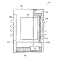
- FIG. 17 shows another example of a conventional vaporization type air conditioner.
- the vaporization type air conditioner 100 includes a water tank 102 disposed in the lower part inside the casing 101 and a water tank 103 disposed in the upper part.
- the water inside the water tank 102 is supplied to the water tank 103 by the pump 104.
- the shaded portions inside the water tank 102 and the water tank 103 represent the stored water.
- Below the water tank 103 an evaporation net 105 is arranged vertically.
- the water trough 103 drops water on the evaporation net 105 in a predetermined amount per hour. Thereby, the evaporation net
- network 105 will be in a moist state.
- the conventional vaporization type air conditioner described in Patent Document 2 includes a blower, a vaporization filter whose lower end is immersed in water in a water tank, and a filter case that holds the periphery of the vaporization filter.
- the room-dried air sucked from the suction port by the blower is passed through the heater and heated, and then passed through the vaporization filter moistened with water in the water tank and blown out from the outlet.
- the filter case is rotatable in parallel with the air passage direction, and opens in the air passage direction so that the right and left parallel to the air passage direction form a flat plate, and the upper and lower surfaces form an arc shape having the same radius as the rotation radius. Further, the upper surface of the air passage through which the filter case passes is formed in an arc shape so as to maintain a predetermined gap from the upper and lower surfaces of the filter case.
- the conventional vaporization type air conditioner described in Patent Document 3 includes a water tank, a water storage unit that stores a predetermined amount of water in the water tank, a rotatable filter member, and a fan.
- the filter member is formed of a plurality of resin plates and the like, and its fitting method is described.
- the evaporation net 105 and the general vaporization filter used in the conventional vaporization type air conditioner described with reference to FIG. 17 may cause clogging due to dust, dust, scale (scale), etc. contained in water. There is. Accordingly, there is a problem that the air permeability is hindered and the cooling efficiency is lowered.
- the evaporation net and the vaporization filter have large air resistance, and a large output is required for the motor that rotates the fan that generates the airflow passing through these. Thereby, there was a problem in power consumption.
- the amount of vaporization at a place where heat exchange is easily performed by air blowing decreases with a decrease in temperature due to vaporization.
- only the portion where the airflow was easily hit was cooled, and the cooling efficiency did not increase.
- the air flow may fluctuate. Therefore, the evaporation net and the vaporization filter are in contact with each other, and a strong air current cannot be generated.
- the evaporation net has a predetermined thickness, even if it is arranged in parallel to the air flow passage, it becomes air resistance and pressure loss increases. As a result, there has been a problem that the number of rotations of the motor that rotates the fan decreases.
- Patent Document 2 tries to overcome this problem by holding the whole with a filter case.
- this filter case has a structure that covers the upper and lower surfaces of the filter and is partially open, but there is a possibility that the air flow passage may be temporarily blocked during rotation.
- a disk structure cannot be employed to hold the filter, and there is a problem that a sufficient surface area cannot be secured for vaporization.
- the vaporization type air conditioner described in Patent Document 3 impregnates the lower part of a rotatable filter member with water and humidifies it with a fan. Since the filter member has a predetermined thickness, there is a problem that even if the filter member is arranged in parallel with the air flow passage, air resistance is generated and pressure loss is increased. Also, once the filter is dry, it will not be effective. Furthermore, the heat conductivity of the filter is poor, and due to the complicated structure, it is difficult to exchange heat with the water in the tank even if the temperature of the water contained in the filter is cooled by evaporation. Moreover, the temperature of the water contained in the filter remained lower than the water temperature of the tank, and the evaporation amount decreased, making it impossible to cool the air sufficiently.
- the present invention has been made in view of the above points, and an object of the present invention is to provide a vaporization type air conditioner that is improved in cooling efficiency when cooling air using heat of vaporization of water. .
- the vaporization type air conditioner of the present invention includes a main body housing that opens an air suction port and an air outlet, an air flow passage that communicates the air inlet and the air outlet, A blower fan that generates an air flow in the air flow passage, and a flat part that is substantially parallel to the air flow direction by the blower fan, such that the flat part faces each other in a direction that is substantially perpendicular to the air flow direction.
- the air flow passage extends in a linear or curved manner in the air flow direction, and the suction port and the blow-out port are substantially opposed to each other. .
- the air coolant is disposed adjacent to the upstream side of the air outlet in the air flow direction.
- the air coolant is made of a metal material and a polymer material having water retention.
- the surface of the metal material constituting the air coolant is subjected to a hydrophilic treatment.
- a part of the air coolant is located in the air flow passage, and is the furthest away from the water storage portion at a peripheral portion based on rotation by the rotation mechanism in the air flow passage.
- the moving direction of the spot is substantially the same as the air flow direction, and the rotation speed is such that a part of the water adhering to the surface of the air coolant is vaporized and a part of the surface of the air coolant is exposed. It is characterized by speed.
- a part of the air coolant is located in the air flow path, and the air coolant is most distant from the water storage section at a peripheral portion based on rotation by the rotation mechanism in the air flow path.
- the moving direction of the distant part is a direction opposite to the air circulation direction.
- the surface area of the air coolant immersed in the water stored in the water reservoir or the liquid containing water is 5% to 50% of the entire surface area of the air coolant. It is characterized by being.
- the plurality of air coolants are arranged substantially parallel to each other.
- the air coolant has at least one of a concave portion and a convex portion on a surface thereof.
- the thermal conductivity of the metal material constituting the air coolant is 30 W / m ⁇ k or more.
- the specific heat of the metal material constituting the air coolant is 0.1 J / g ⁇ ° C. or more and 2.0 J / g ⁇ ° C. or less.
- the vaporization type air conditioner configured as described above is characterized by comprising a water supply container that contains water or a liquid containing water and that can be attached to and detached from the water storage unit and can supply water.
- the water supply container is hermetically sealed except for a portion communicating with the water storage unit.
- the water supply container is provided with a valve at a location communicating with the water storage unit.
- the rotation mechanism is capable of changing a rotation speed and a rotation direction of the air coolant.
- the rotation mechanism changes the rotation speed of the air coolant based on at least one of ambient temperature and ambient humidity.
- the water storage section includes a water passage hole through which water flows to the surface of the air coolant.
- FIG. 13 is a horizontal sectional view taken along line XV-XV of the lid of the water storage section shown in FIG. It is a general
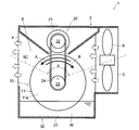
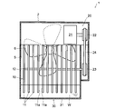
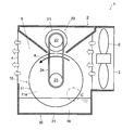
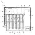
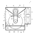
- FIGS. 1 and 2 are a schematic vertical sectional side view and a schematic vertical sectional front view of a vaporization type air conditioner.
- FIG. 3 is a schematic perspective view of the air coolant of the vaporization type air conditioner.
- the white arrow drawn in FIG.1 and FIG.3 shows the distribution path and distribution direction of the airflow produced by a ventilation fan.
- the dashed-two dotted line drawn on FIG. 1 shows the approximate center line of the up-down direction of an airflow path.
- the vaporizing air conditioner 1 includes a main body housing 2 having a rectangular box shape as shown in FIG.
- the main body housing 2 includes therein an air flow passage 5 that communicates an air suction port 3 opened at one end thereof with an air outlet 4 opened at the other end.
- the main body housing 2 includes a blower fan 6, a cooling unit 10, a rotation mechanism 20, and a water storage unit 30 inside. It is desirable that the blower fan 6 and the cooling unit 10 are arranged along an air flow direction that forms a straight line inside the main body housing 2.
- the air flow direction extends substantially linearly, and the suction port 3 and the air outlet 4 face each other. More specifically, the air flow passage 5 has an air flow direction approaching the water W of the lower water storage section 30 in the cooling section 10 as indicated by a two-dot chain line in FIG. It extends so as to be curved. Air flow such that the angle ⁇ between the path from the suction port 3 to the cooling unit 10 and the path from the cooling unit 10 to the blower outlet 4 exceeds 120 ° with respect to the substantially center line 5C in the vertical direction of the air flow passage 5. It is preferable to form the path 5. Thereby, pressure loss can be reduced. And a strong wind can be applied to the cooling part 10, and it is possible to raise the wind speed of the blower outlet 4 further.
- blower fan 6 for example, an axial fan, a cross flow fan, a sirocco fan or the like is used, and is arranged closer to the suction port 3 than the cooling unit 10.
- the blower fan 6 generates an air flow in the air flow passage 5 in the direction in which the air sucked into the main body housing 2 from the suction port 3 is blown to the cooling unit 10, that is, from the right to the left in FIG.
- the cooling unit 10 is disposed inside the main body housing 2 on the downstream side in the air flow direction with respect to the blower fan 6.
- the cooling unit 10 blows air that has been cooled by exchanging heat with the inside of the main body housing 2, that is, with air flowing through the air flow passage 5.
- the air cooled by the cooling unit 10 is blown out of the main body housing 2 from the air outlet 4. Since the cooling unit 10 is close to the air outlet 4, cooler air can be blown out of the main body housing 2.
- the cooling unit 10 is disposed on the downstream side in the air flow direction with respect to the blower fan 6, but is not limited to this arrangement, and is disposed on the upstream side with respect to the blower fan 6. May be. In this case, the air sucked into the main body housing 2 by the rotation of the blower fan 6 is cooled by the cooling unit 10, passes through the blower fan 6, and is blown out from the blower outlet 4 to the outside of the main body housing 2.
- the cooling unit 10 includes an air coolant 11 and a shaft 12 as shown in FIGS.
- FIG. 3 shows a part of the air coolant 11 and the shaft 12.
- the air coolant 11 has a circular plate shape, and a plurality of air coolants 11 are fixed to each other with a predetermined interval on a shaft 12 penetrating the center.
- the shaft 12 has an axis extending in a horizontal direction substantially perpendicular to the air flow direction.
- a part of the air coolant 11 is located inside the air flow passage 5, and the other part is immersed in the water W of the water storage unit 30.
- a portion of the air coolant 11 is immersed in the water W of the water storage unit 30 to cool the surrounding air and the air coolant 11 itself using the heat of vaporization of the water W adhering to the air coolant 11.
- the rotation mechanism 20 includes a motor 21, a first pulley 22, a second pulley 23, and a belt 24 as shown in FIGS.
- the shaft portion of the motor 21 is connected to the first pulley 22.
- the shaft 12 of the cooling unit 10 is connected to the second pulley 23.
- the belt 24 is wound around the first pulley 22 and the second pulley 23.
- the rotation mechanism 20 has a direction (arrow A in FIG. 1) in which the moving direction of the peripheral edge portion of the portion located inside the air flow passage 5 of the air coolant 11 substantially coincides with the air flow direction, or a direction that is substantially opposite (see FIG. 1 can be rotated in either direction of arrow B).
- the rotating mechanism 20 uses the first pulley 22, the second pulley 23, and the belt 24 to rotate the air coolant 11, but a gear mechanism may be used instead of the pulley or the belt.
- the water storage unit 30 includes a water storage container 31 as shown in FIGS. 1 and 2.
- the water storage container 31 is arrange
- the water storage container 31 includes a water level sensor (not shown) therein.
- the water storage container 31 is adjusted based on the water level information obtained from the water level sensor so that the stored water W maintains a predetermined amount or more.
- the water level sensor can also notify that the water W inside the water storage container 31 has been exhausted.
- a method using the principle of Trichelli can be used as another liquid level adjusting method.
- the lower part of the air coolant 11 is immersed in the water W of the water storage container 31 and comes into contact therewith.
- the method of bringing water into contact with the air coolant 1 is not limited to this, and other methods may be used. For example, a method of placing a water-retaining cloth or sponge-like member below the air coolant 11 and bringing it into contact with the air coolant 11 may be used. By such a method, the water W can be brought into contact with the air coolant 11.
- the air blowing fan 6 and the rotating mechanism 20 are driven. Thereby, the vaporization type air conditioner 1 sucks the air outside the vaporization type air conditioner 1 through the suction port 3 into the main body housing 2.
- the blower fan 6 generates an air flow in the air flow passage 5 in a direction in which air is blown against the air coolant 11 of the cooling unit 10.
- the motor 21 is driven, and the air coolant 11 having a circular plate shape rotates at a relatively low speed via the first pulley 22, the belt 24, the second pulley 23, and the shaft 12. Since the lower part of the air coolant 11 is immersed in and contacts the water W of the water storage container 31, water continuously adheres to the surface of the air coolant 11 and the like by the rotation of the rotation mechanism 20.
- the air coolant 11 continues the surrounding air and the air coolant 11 itself using the heat of vaporization when water attached to the air coolant 11 is vaporized. Cool. Furthermore, when the cooled air coolant 11 is immersed in the water W of the water storage container 31, heat exchange is performed between the water W and the water W is cooled. On the contrary, since the temperature of the air coolant 11 rises to the water temperature, when the portion that is further rotated and immersed in the water W is exposed from the water W to the air flow passage 5, the amount of evaporation is the same as the amount of evaporation before one rotation. Keep to cool the air. Since heat exchange is difficult in the conventional filter type, the filter gets cold and the amount of evaporation decreases.
- the rotation speed of the air coolant by the rotation mechanism 20 is such a speed that a part of the water film adhering to the surface of the air coolant 11 evaporates and a part of the base material of the air coolant 11 is exposed. If the speed is such that a part of the base material of the air coolant 11 is exposed, the water film attached to the surface of the air coolant 11 is the thinnest. Thereby, the fine unevenness
- the air blown to the air coolant 11 by the blower fan 6 is cooled by exchanging heat with water or the air coolant 11 when flowing through the surface of the air coolant 11.
- the air thus cooled is blown out of the vaporization type air conditioner 1 from the blowout port 4.
- the inside of the water storage container 31 and the water W can be sterilized by installing a sterilizing lamp in the upper part of the water storage unit 30 or installing a member for injecting a sterilizing component into the water W inside the water storage container 31.
- the water quality may be improved.
- Each of the plurality of air coolants 11 has a flat portion 11a that is substantially parallel to the air flow direction by the blower fan 6.
- the air coolant 11 is provided in a state where the flat surface portion 11a is erected so as to be substantially vertical.
- the flat portion 11a of the air coolant 1 may not be completely flat, and may be, for example, a corrugated plate shape, a shape obtained by bending a thin plate into a zigzag shape, or a plate irregularly formed with wrinkles. .
- the air coolant 11 is preferably made of, for example, a metal plate, and a metal material having a higher heat transfer coefficient is used.
- a metal material having a higher heat transfer coefficient As the metal, aluminum or stainless steel that hardly causes rust, or steel subjected to rust prevention treatment is used.
- a metal having high thermal conductivity for the air coolant 11 even if water is locally vaporized and cooled at a location where heat exchange is easily performed by air blowing, that is, where airflow is easily hit, the temperature of the location is decreased. Is alleviated. If it is the conventional evaporation net
- the air coolant 11 when the air coolant 11 is made of a metal material, heat is easily released from the metal to the water even if the amount of vaporization decreases when the water adhering to the surface is lower than the temperature. Furthermore, if the air coolant 11 is made of a metal material having a higher heat transfer coefficient, the transfer efficiency of latent heat when water vaporizes increases, and the air coolant 11 can be cooled more efficiently. From these things, the cooling efficiency of the vaporization type air conditioner 1 improves.
- the plurality of air coolants 11 are arranged side by side with a predetermined interval so that the plane portions 11a face each other in a direction substantially perpendicular to the air flow direction.
- the air blown to the air coolant 11 by the blower fan 6 smoothly flows between the adjacent air coolants 11.
- the air coolant 11 is made of a metal material having a high heat transfer coefficient, heat exchange is facilitated by increasing the length in the air flow direction, thereby improving the cooling efficiency.
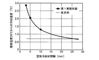
- FIG. 4 is a graph showing a difference in cooling temperature between the vaporization type air conditioner 1 of the first embodiment and the vaporization type air conditioner 100 of the conventional example
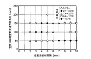
- FIG. 5 is a graph showing the distance between the air coolant 11 and the length of the air flow direction. It is a graph which shows the influence which a relationship has on cooling temperature.
- a conventional vaporization type air conditioner 100 which is a comparison target of the vaporization type air conditioner 1 of the first embodiment is an apparatus shown in FIG.
- the environmental temperature from 35 ° C under the conditions of the environmental temperature of 35 ° C and the humidity of 80% The difference in cooling temperature was verified.
- the vaporization type air conditioner 1 of 1st Embodiment it experimented by changing the space
- the vertical axis in FIG. 4 indicates the cooling temperature (° C.) of air from the ambient temperature of 35 ° C., and the horizontal axis indicates the interval (mm) between the plurality of air coolants 11.
- the cooling temperature of the air in the conventional vaporization type air conditioner 100 is 0.7 ° C. and hardly decreases.
- the cooling temperature of the air of the vaporization type air conditioner 1 of the first embodiment is 2.9 ° C. when the interval of the air coolant 11 is 3 mm, 2.0 ° C. when 5 mm, and 1.3 ° C. when 10 mm. Both show high cooling performance.
- the same cooling temperature of 0.7 ° C. as that of the vaporization type air conditioner 100 of the conventional example is shown when the interval of the air coolant 11 exceeds 26 mm. .
- the interval between the plurality of air coolants 11 is preferably 26 mm or less, and more preferably about 3 mm to 10 mm.
- the length of the air coolant 11 in the air flow direction means the length of the air coolant 11 along the air flow direction and the diameter of the air coolant 11 in FIG.
- interval of the air coolant 11 and an air distribution direction length has on cooling temperature was verified.
- the interval between the plurality of air coolants 11 is changed every 1 mm from 2 mm to 10 mm, and the length of the air flow direction of the air coolant 11 is changed every 50 mm from 50 mm to 200 mm. And experimented.
- the vertical axis in FIG. 5 indicates the length (mm) of the air coolant 11 in the air flow direction, and the horizontal axis indicates the interval (mm) between the plurality of air coolants 11.
- the cooling temperature of the air by the vaporization type air conditioner 1 of the first embodiment when the air flow direction length of the air coolant 11 is 50 mm and the interval between the plurality of air coolants 11 is 7 mm or more, the cooling temperature of the air by the vaporization type air conditioner 1 of the first embodiment. It turns out that is 0.7 degrees C or less. If the performance equal to or better than the air cooling temperature of 0.7 ° C. of the conventional vaporization type air conditioner 100 described with reference to FIG. 4 is required, the air circulation direction length of the air coolant 11 is set to 50 mm or more. It is preferable to set the interval between the plurality of air coolants 11 to about 8 mm or less. As a result, the vaporization type air conditioner 1 according to the first embodiment having the above-described configuration has improved cooling efficiency compared to the conventional vaporization type air conditioner 100.
- FIG. 6 is a schematic vertical sectional side view of the vaporization type air conditioner. Since the basic configuration of this embodiment is the same as that of the first embodiment described above, the same components as those of the first embodiment are denoted by the same reference numerals as before, and the description of the drawings and the description thereof. Shall be omitted.
- the vaporization type air conditioner 1 includes a peripheral portion of a portion where the rotation mechanism 20 is located inside the air flow passage 5 of the air coolant 11, that is, the water storage portion at the peripheral portion.
- the air coolant 11 is rotated in a direction (arrow A in FIG. 6) in which the moving direction of the part farthest from the center substantially coincides with the air circulation direction.
- Table 1 shows the results of confirming the effects of the configuration of the vaporization type air conditioner 1 according to the second embodiment by experiments.
- Table 1 shows the results of confirming the effects of the configuration of the vaporization type air conditioner 1 according to the second embodiment by experiments.
- Comparative Example 1 air is moved in a direction (see arrow B in FIG. 1) in which the movement direction of the peripheral portion of the portion located inside the air flow passage 5 of the air coolant 11 is substantially opposite to the air flow direction. The results when the coolant 11 was rotated are also shown.
- the air coolant 11 is rotated in a direction in which the moving direction of the peripheral portion of the portion located inside the air flow passage 5 of the air coolant 11 substantially coincides with the air flow direction. It can be seen that the amount of temperature decrease is greater in the second embodiment than in the first comparative example in which the air coolant 11 is rotated in a direction that is substantially opposite.
- a part of the air coolant 11 that has appeared inside the air flow passage 5 is further lowered in temperature from the same level as the water temperature due to vaporization of water, and is downstream in the air circulation direction, that is, in the vicinity of the outlet 4.
- the amount of temperature decrease is further increased.
- the humidity of air becomes comparatively high by vaporization of water in the vicinity of the blower outlet 4.
- a part of the air coolant 11 located inside the air flow passage 5 is immersed in the water W of the water storage unit 30 and has a temperature similar to the water temperature. At this time, if the temperature of the air coolant 11 is lower than the water temperature, the water W itself of the water storage unit 30 is cooled, and the air coolant 11 is heat-exchanged and the temperature rises to near the water temperature.
- the dry and warm air before cooling that has flowed into the air flow passage 5 is initially water having a relatively high temperature in the portion located inside the air flow passage 5 of the air coolant 11. It touches the part where much adheres. As a result, the amount of water vaporized increases and the cooling efficiency improves.
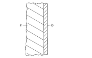
- FIG. 7 is a partial cross-sectional view of the air coolant of the vaporization type air conditioner. Since the basic configuration of this embodiment is the same as that of the first embodiment described above, the same components as those of the first embodiment are denoted by the same reference numerals and the description thereof is omitted. And
- the air coolant 11 is made of a plate-shaped metal material. And the hydrophilic process which forms the hydrophilic thin film 13 on the surface of the air-cooling material 11 which consists of metal materials is performed. On the surface of the hydrophilic thin film 13, the water that comes into contact is not repelled and tends to stay.
- the hydrophilic treatment it is conceivable to apply a highly hydrophilic coating on the surface of the metal material.
- the air coolant 11 is made of aluminum, it is hydrophilized by applying a paint containing any of silica, titanium oxide, and alumina, or by forming a sol-gel film, a sprayed film, or a plated film.
- the air coolant 11 may be formed of a metal material and a polymer material having water retention.
- a metal material may be attached to the surface of the metal material, or a polymer film having a fine structure such as a moth-eye film may be attached.
- Table 2 shows the results of confirming the effects of the configuration of the vaporization type air conditioner 1 according to the third embodiment.
- the surface temperature of the normal air cooling material 11 made of aluminum that was not subjected to hydrophilic treatment was 26.4 ° C. at an environmental temperature of 30 ° C. and a humidity of 40%.
- the surface temperature of the air cooling material 11 made of aluminum subjected to hydrophilic treatment with a contact angle of 20 ° to 30 ° was 25.0 ° C.
- the surface temperature of the air cooling material 11 made of aluminum subjected to the hydrophilic treatment having a contact angle of 10 ° or less became 22.8 ° C. It was found that the lower the contact angle, that is, the higher the degree of hydrophilicity, the lower the temperature of the aluminum air coolant 11.
- the boundary layer between the surface of the air coolant 11 and the water becomes thin. Since water vaporization (evaporation) occurs on the surface of the water film, by making the water film thinner, water vaporization transmission is promoted and heat transfer efficiency is further improved. Therefore, the air coolant 11 can be cooled more efficiently, and the cooling capacity of the vaporization type air conditioner 1 is improved.
- FIG. 8 is a graph showing the influence of the arrangement of the air coolant of the vaporization type air conditioner on the cooling temperature. Since the basic configuration of this embodiment is the same as that of the first embodiment described above, the same components as those of the first embodiment are denoted by the same reference numerals and the description thereof is omitted. And
- a plurality of air coolants 11 are arranged substantially parallel to each other.
- the result of having verified the difference in cooling temperature with respect to this vaporization type air conditioner 1 and the vaporization type air conditioner of a comparative example is shown in FIG.
- a plurality of air coolants are not arranged in parallel to each other (non-parallel arrangement), and there are narrow places and wide places.
- the vertical axis in FIG. 8 indicates the temperature difference from the environmental temperature (air cooling temperature relative to the environmental temperature) (° C.), and the horizontal axis indicates the distance (cm) from the air coolant outlet.
- the diameter of the air coolant 11 is 100 mm.
- the cooling temperature of the air of the vaporization type air conditioner of the comparative example in which the plurality of air coolants are not parallel to each other was 3.2 ° C. at the outlet.
- the cooling temperature of the air of the vaporization type air conditioner 1 of the fourth embodiment in which a plurality of air coolants 11 are arranged in parallel to each other is 4.5 ° C. at the outlet 4, indicating high cooling performance.
- the air coolant 11 in parallel as in the vaporization type air conditioner 1 of the fourth embodiment, the air flow between the adjacent air coolants 11 can be made uniform. Therefore, the air is effectively cooled as compared with the vaporization type air conditioner of the comparative example in which the plurality of air coolants are not parallel to each other, and the cooling efficiency is improved.
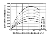
- FIG. 9 is a graph showing the influence of the immersion depth with respect to the diameter of the air coolant of the vaporization type air conditioner on the water adhesion area of the air coolant. Since the basic configuration of this embodiment is the same as that of the first embodiment described above, the same components as those of the first embodiment are denoted by the same reference numerals and the description thereof is omitted. And
- the surface area immersed in the water of the water storage section 30 of the air coolant 11 is 5% to 50% of the entire surface area of the air coolant 11.
- the surface area of the air coolant 11 where the immersion depth with respect to the diameter of the air coolant 11 having a circular plate shape is exposed to the air circulation space of the air flow passage 5, that is, the water adhesion area of the air coolant 11.
- FIG. 9 shows the results.
- the vertical axis of FIG. 9 indicates the water adhesion area (mm 2 ) of the air coolant 11, and the horizontal axis indicates the ratio (%) of the immersion depth to the diameter of the air coolant 11.
- the diameter of the air coolant 11 was verified in increments of 10 mm from 80 mm to 130 mm.
- the region where the water of the air coolant 11 is not attached and immersed is It is expressed by the following formula.
- the immersion depth with respect to the diameter of the air coolant 11 is 25%, and the interval between the air coolants 11 is 6 mm.
- the cooling temperature was about 4.5 ° C. at the maximum.
- the vaporization amount is about 6.4 times the maximum. It corresponds to. That is, it is considered that the water adhesion area in the evaporation net 105 of the vaporization type air conditioner 100 of the conventional example is about 1 / 6.4 of the vaporization type air conditioner 1 of the fifth embodiment.
- the water adhesion area of the air coolant 11 is about 55% of the entire surface area of the air coolant 11. If the adhesion area of water on the evaporation net 105 of the vaporization type air conditioner 100 of the conventional example is about 1 / 6.4 of the vaporization type air conditioner 1 of the fifth embodiment, the entire surface area of the air coolant 11 Is equivalent to about 8.5%.
- the cooling temperature can be further lowered.
- 1.6 with respect to the maximum cooling temperature of about 4.5 ° C. which is the result when the interval of the air coolant 11 of the vaporization type air conditioner of the fourth embodiment described with reference to FIG. 8 is 6 mm. It may be possible to further reduce the cooling temperature by about twice. Then, 8.5% of the entire surface area of the air coolant 11, which is the water adhesion area of the air coolant 11, is divided by 1.6 to be about 5%. Thereby, if the adhesion area of the water of the air coolant 11 is 5% of the whole surface area of the air coolant 11, it is thought that the cooling performance of the same level as the vaporization type air conditioner 100 of a prior art example is obtained.
- the water adhesion area of the air coolant 11, that is, the surface area immersed in the water of the water storage portion 30 of the air coolant 11 is 5% or more of the entire surface area of the air coolant 11, that is, the water level It is preferable to be immersed at a depth of 1.5% or more of the diameter of the material 11.
- the water adhesion area of the air coolant 11, that is, the surface area immersed in the water of the water storage portion 30 of the air coolant 11 exceeds 50% of the entire surface area of the air coolant 11, the main body starts from the location of the shaft 12. Water leaks outside the housing 2. Therefore, the water adhesion area of the air coolant 11, that is, the surface area immersed in the water of the water reservoir 30 of the air coolant 11 is preferably 5% to 50% of the entire surface area of the air coolant 11.
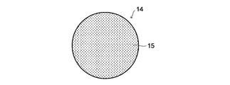
- FIG. 10 is an explanatory diagram of the air coolant of the vaporization type air conditioner and is a view seen from a direction perpendicular to the air flow direction. Since the basic configuration of this embodiment is the same as that of the first embodiment described above, the same components as those of the first embodiment are denoted by the same reference numerals and the description thereof is omitted. And
- the air coolant 14 is made of a plate-like metal material, for example, aluminum. And as shown in FIG. 10, the uneven
- the uneven portion 15 on the surface of the air coolant 14 may be provided by embossing, porous processing (including the case of using a porous material), or satin processing. According to this structure, the contact area with respect to the water and air of the air coolant 14 becomes very large for the volume, and cooling efficiency improves.
- the vaporization type air conditioner 1 of the above embodiment utilizes the effect of lowering the temperature due to vaporization (evaporation) of water adhering to the surface of the air coolant 11. At the same time, heat exchange is performed between the air coolant 11 cooled by the vaporization of water and the water inside the water storage unit 30 disposed at the lower portion, thereby cooling the water together. If the water cooled in this way comes to function as a cold storage material, even if the rotation of the air coolant 11 is stopped and the amount of vaporization is reduced, if the thermal conductivity of the air coolant 11 is relatively high, The air can be cooled for a certain time. Thereby, reduction of power consumption, adjustment of a humidification amount, etc. are realizable.
- the thermal conductivity of the air coolant 11 is preferably 50 W / m ⁇ k or more.
- the temperature of the water is about 20 ° C.
- the air coolant 11 is made of aluminum and the thermal conductivity per sheet is 237 W / m ⁇ k, the temperature difference between air and water temperature is 8 k, and the center of the air flow passage 5 is up to 2 cm.
- the cooling capacity per sheet of the air coolant 11 is expressed by the following equation.
- the cooling capacity per sheet of the air coolant 11 is 1.9 W. If the number of the air coolants 11 is 15, the vaporization type air conditioner 1 has a cooling capacity of about 29 W.
- the thermal conductivity of the metal material constituting the air coolant 11 is 30 W / m ⁇ k or more.
- the specific heat of the air coolant 11 is preferably 0.1 J / g ⁇ ° C. or more and 2.0 J / g ⁇ ° C. or less. If the specific heat of the air coolant 11 is too low, even if it is cooled by the heat of vaporization, it is immediately warmed by external air. If the specific heat of the air coolant 11 is too high, the air coolant 11 itself is hardly cooled even if the heat is taken away by the heat of vaporization. Therefore, in the vaporization type air conditioner 1 of the seventh embodiment, the specific heat of the metal material constituting the air coolant 11 is 0.1 J / g ⁇ ° C. or more and 2.0 J / g ⁇ ° C. or less.
- FIG. 11 is a schematic vertical sectional front view of the vaporization type air conditioner. Since the basic configuration of this embodiment is the same as that of the first embodiment described above, the same components as those of the first embodiment are denoted by the same reference numerals and the description thereof is omitted. And
- the vaporization type air conditioner 1 of 8th Embodiment is provided with the water supply container 40 as shown in FIG.
- the water supply container 40 accommodates water W and is detachable from the water storage unit 30 and can supply water.
- the water supply container 40 has a vertically long form, and is arranged upright with the water supply port 41 facing down so that its longitudinal direction is substantially vertical.
- the water supply port 41 communicates with the water storage container 31 and replenishes the water W inside the water supply container 40 as water W inside the water storage container 31.
- the water W inside the water supply container 40 is supplied to the water storage container 31 by the action of gravity.
- the water supply container 40 is sealed except for the water supply port 41 communicating with the water storage container 31.
- the water supply container 40 includes a valve 42 at a water supply port 41.
- the valve 42 is configured by, for example, a valve using a spring, and automatically adjusts the water level of the water storage container 31 to be constant according to the Torrichelli principle.
- the air flows into the sealed water supply container 40, and the water W is discharged from the water supply container 40.
- the water level of the water supply container 40 becomes approximately the same as the water level of the water storage container 31, that is, when the water W inside the vaporization type air conditioner 1 is almost empty, the water supply container 40 is filled with water and the vaporization type air conditioner is once again. 1 can be installed.
- the valve 42 is closed, so that the water W hardly leaks.
- the water level of the vaporizing air conditioner 1 can be stabilized for a certain period of time, and high cooling performance can be maintained.
- FIG. 12 is a schematic vertical sectional side view of a vaporization type air conditioner.
- FIG.13 and FIG.14 is the perspective view and top view of the cover of the water storage part of a vaporization type air conditioner.
- FIG. 15 is a horizontal sectional view taken along line XV-XV of the lid of the water storage section shown in FIG. Since the basic configuration of this embodiment is the same as that of the first embodiment described above, the same components as those of the first embodiment are denoted by the same reference numerals and the description thereof is omitted. And
- the water storage part 30 is provided with the lid
- the lid 32 totally closes the upper surface opening of the water storage container 31.
- the lid 32 is provided with a plate-like portion 32 a and an accommodating portion 32 b.
- the plate-like portion 32 a of the lid 32 has a rectangular shape, and is arranged so that the flat portion covers the water surface of the water storage container 31.
- the plate-like portion 32 a includes a plurality of insertion holes 32 c that have a rectangular slit shape and penetrate vertically.
- the insertion holes 32 c are provided at positions corresponding to the air coolants 11 in quantities corresponding to the plurality of air coolants 11. A part of the lower side of the air coolant 11 is inserted through the insertion holes 32c one by one.
- the housing portion 32 b of the lid 32 has a shape consisting of a part of the lower side that is cut horizontally and with a cylinder closed at both ends, and is a rectangular opening that appears on the cut surface. Is attached to the lower surface of the plate-like portion 32a.
- the accommodating part 32b covers the entrance / exit on the lower surface side of the plate-like part 32a of all the insertion holes 32c.
- the cylinder forming the accommodating portion 32b has an axis that coincides with the axis of the air coolant 11 having a circular plate shape, and the diameter thereof is larger than the diameter of the air coolant 11.
- the accommodating part 32b accommodates so that a part of air-cooling material 11 which appears on the lower side of the plate-shaped part 32a through the insertion hole 32c may be covered.
- the accommodating part 32b is provided with a plurality of water passage holes 32d at the lowermost part thereof as shown in FIGS.
- the water passage hole 32d is provided so as to penetrate from the inside to the outside of the housing portion 32b.
- the water W stored in the water storage container 31 flows between the outside and the inside of the housing portion 32b through the water passage hole 32d.
- the position of the water passage hole 32d is not limited to the lowermost part of the accommodating part 32b, and may be another part of the accommodating part 32b. Further, the quantity of the water passage holes 32d is not limited to the quantity shown in FIG.
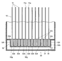
- FIG. 16 is a schematic vertical sectional front view showing a cooling unit and a water storage unit of the vaporization type air conditioner. Since the basic configuration of this embodiment is the same as that of the ninth embodiment described above, the same components as those of the ninth embodiment are denoted by the same reference numerals as those of the previous embodiment, and the description thereof is omitted. And
- the lid 32 includes a partition 32e inside the accommodating portion 32b as shown in FIG.
- the partition 32e has a plate shape that is the same as the vertical cross-sectional shape of the housing portion 32b that is orthogonal to the axis of the cylinder that forms the outer shape of the housing portion 32b, that is, the vertical cross-sectional shape of the housing portion 32b that is parallel to the depth direction in FIG. .
- a plurality of the partitions 32e are arranged between the adjacent air coolants 11 in parallel with the flat portion 11a of the air coolant 11.
- the insertion hole 32c is located between the adjacent partitions 32e or between the vertical wall 32f of the housing portion 32b and the partition 32e.
- Each of the plurality of air coolants 11 is between the partition 32e and the cylindrical wall of the accommodating portion 32b, each of which is partly adjacent to the lower side, or between the vertical wall 32f of the accommodating portion 32b, the partition 32e, and the cylindrical wall of the accommodating portion 32b. It is accommodated in a small region 32g inside the accommodating portion 32b formed in the above. Each small region 32g of the accommodating portion 32b is provided with at least one water passage hole 32d. The water W stored in the water storage container 31 flows between the outside and the inside of each of the small regions 32g of the housing portion 32b through the water passage hole 32d.
- the interval between the air coolant 11 and the partition 32e is not particularly limited, but is preferably set to about 1.0 mm to 5.0 mm.
- the amount of water W contained in the accommodation part 32b (small region 32g) is an amount necessary for the air coolant 11. To be suppressed. Thereby, the leakage of the water W which the water storage container 31 stores when the vaporization type air conditioner 1 falls is further suppressed with respect to the vaporization type air conditioner 1 of 9th Embodiment. Therefore, the safety of the vaporization type air conditioner 1 is further improved.
- the vaporization type air conditioner 1 of the present embodiment includes the main body housing 2 that opens the air inlet 3 and the air outlet 4, and the air flow passage 5 that allows the air inlet 3 and the air outlet 4 to communicate with each other. And a blower fan 6 that generates an airflow in the airflow passage 5 and a flat surface portion 11a that is substantially parallel to the air flow direction by the blower fan 6, and the flat surface portion 11a is opposed to a direction that is substantially perpendicular to the air flow direction.
- a plurality of circular plate-like air coolants 11 arranged side by side so as to be in contact with each other, and a rotation mechanism that rotates the air coolant 11 around an axis extending in a direction substantially perpendicular to the air flow direction. 20.
- the blower fan 6 and the air coolant 11 when the blower fan 6 and the air coolant 11 are rotated, air can be smoothly circulated between the plurality of plate-like air coolants 11. That is, the air flow passage is not blocked unlike the filter case found in the prior art. And by making the air-cooling material 11 into a substantially circular plate shape, the surface area can be increased, the amount of vaporization increases, and the cooling temperature associated therewith also increases. Further, if the air coolant 11 is polygonal, particularly hexagonal or octagonal, more air coolant 11 can be formed from a single plate, so that the material utilization efficiency is increased.
- the air coolant 11 by configuring the air coolant 11 with a metal material or a ceramic material, even if water is vaporized locally and cooled at a location where heat exchange is easily performed by blowing air, that is, where airflow is easily hit, The temperature drop is alleviated. If it is the conventional evaporation net
- the air coolant 11 when the air coolant 11 is made of a metal material, heat is easily released from the metal to the water even if the amount of vaporization decreases when the water adhering to the surface is lower than the temperature. Furthermore, if the air coolant 11 is made of a metal material or a ceramic material having a higher heat transfer coefficient, the transfer efficiency of latent heat when water vaporizes increases, and the air coolant 11 can be cooled more efficiently. is there. From these things, it is possible to improve the cooling efficiency of the vaporization type air conditioner 1.
- the air coolant 11 is made of a material containing a lot of metal elements. Specifically, it is desirable that it is aluminum used especially for an air conditioner. If it is aluminum, the fluttering by a wind, etc. can be suppressed. Further, since the air coolant 11 is made of a metal material, mold and the like are hardly generated. Thereby, the conventional subject can be solved at a stretch.
- the vaporization type air conditioner 1 includes a water storage unit 30 that stores the water W, and a part of the air coolant 11 is in contact with the water W of the water storage unit 30, the air cooling is performed by the rotation of the rotation mechanism 20.
- the flat portion 11a of the material 11 can be brought into contact with the water W over a wide range.
- the air coolant 11 is rotated at a relatively low speed, the water W continuously adheres to the air coolant 11.
- the heat of vaporization of water adhering to the air coolant 11 can continuously cool the air coolant 11 itself and the surrounding air.
- the cooled air coolant 11 can cool the air by exchanging heat with the air flowing around it.
- the air flow passage 5 is curved and extended so that the air flow direction approaches the water W of the lower water storage section 30 in the cooling section 10, and the suction port 3 and the outlet 4 are substantially opposed to each other. Can be reduced. And a strong wind can be applied to the cooling part 10, and it is possible to raise the wind speed of the blower outlet 4 further. In addition, you may form the airflow path 5 so that it may extend linearly.
- the air coolant 11 is disposed adjacent to the upstream side of the air outlet 4 in the air flow direction. According to this configuration, cooler air can be blown out of the main body housing 2.
- the air coolant 11 is formed of a metal material and a polymer material having water retention, it is possible to enhance the action of water remaining on the surface of the air coolant 11. Therefore, the air coolant 11 can be cooled more efficiently, and the cooling capacity of the vaporization type air conditioner 1 can be improved.
- the vaporization type air conditioner 1 performed the hydrophilic process on the surface of the air coolant 11, when water adheres to the surface of the air coolant 11, the boundary layer between the surface of the air coolant 11 and water is formed. getting thin. Since water vaporization (evaporation) occurs on the surface of the water film, by making the water film thinner, water vaporization transmission is promoted, and heat transfer efficiency can be further improved. Therefore, the air coolant 11 can be cooled more efficiently, and the cooling efficiency of the vaporization type air conditioner 1 can be improved.
- air coolant 11 by comprising the air coolant 11 with aluminum, it is easy to maintain the shape because of its high thermal conductivity despite being a thin plate. Moreover, since the hydrophilic process was performed to the surface of the air-cooling material 11, water can be hold
- the hydrophilic treatment on the surface of the air coolant 11 allows the water attached to the surface of the air coolant 11 arranged vertically to stay longer. Therefore, the air coolant 11 can be cooled more efficiently, and the cooling efficiency of the vaporization type air conditioner 1 can be improved.
- a part of the air coolant 11 is located inside the air flow passage 5, and the moving direction of the portion farthest from the water storage portion 30 at the peripheral portion based on the rotation by the rotation mechanism 20 in the air flow passage 5 is the air flow. It almost coincides with the direction. Thereby, the position where the most downstream part in the rotation direction is closest to the suction port 3 among the immersion parts of the air coolant 11 that is located outside the air flow passage 5 and is immersed in the water W of the water storage unit 30 by the rotation by the rotation mechanism 20. And appears inside the air flow passage 5. Therefore, the dry warm air before cooling that has flowed into the air flow passage 5 can first be brought into contact with the portion of the air coolant 11 where the most water adheres among the portions located inside the air flow passage 5. . As a result, the amount of water vaporized can be increased, and the cooling efficiency can be improved.
- a part of the air coolant 11 that has appeared inside the air flow passage 5 is further lowered in temperature from the same level as the water temperature due to vaporization of water, and is downstream in the air circulation direction, that is, in the vicinity of the outlet 4.
- the amount of temperature decrease is further increased.
- the humidity of air becomes comparatively high by vaporization of water in the vicinity of the blower outlet 4.
- a part of the air coolant 11 located inside the air flow passage 5 is immersed in the water W of the water storage unit 30 and has a temperature similar to the water temperature. At this time, if the temperature of the air coolant 11 is lower than the water temperature, the water W itself of the water storage unit 30 is cooled, and the air coolant 11 is heat-exchanged and the temperature rises to near the water temperature.
- the dry warm air before cooling that has flowed into the air flow passage 5 is the water having a relatively high temperature among the portions of the air coolant 11 that are located inside the air flow passage 5. It can be made to contact the location where much adheres. As a result, the amount of water vaporized can be increased, and the cooling efficiency can be improved.
- the rotation speed of the air coolant 11 is approximately the speed just before completion of vaporization at the portion of the air coolant 11 on the outlet 4 side, the water vaporization speed becomes the highest.
- the water film on the surface of the air coolant 11 is the thinnest immediately before the completion of vaporization, so that the influence of the unevenness on the surface of the air coolant 11 can be remarkably exhibited, and the cooling performance becomes the highest.
- the rotation mechanism 20 may change the rotation speed of the air coolant 11 based on at least one of the ambient temperature and the ambient humidity.
- cooling performance becomes still higher.
- the water vaporization rate is fast in high temperature or dry environments and slow in low temperature or humid environments. Therefore, if the rotation speed of the air coolant 11 is further increased in a high temperature or dry environment, the cooling efficiency is further increased.
- the temperature is 28 ° C. and the humidity is about 45%
- a part of the air coolant 11 tends to start drying at about several rpm, and the cooling performance becomes the highest.
- the rotation direction of the air coolant 11 it is most that the moving direction of the location farthest from the water storage part 30 of the peripheral part based on the rotation by the rotation mechanism 20 in the air flow passage 5 substantially coincides with the air circulation direction. preferable.
- the area where the air coolant 11 having a circular plate shape is in contact with water can be stably maintained at 10% to 50% of the diameter of the air coolant 11. More preferably, it is about 35% of the diameter of the air coolant 11.
- the air cooling material 11 having a circular plate shape rotates, the water in the water storage unit 30 adheres to the entire periphery. However, since air does not flow in the portion of the air coolant 11 that is immersed in water, it is sufficient that the area obtained by subtracting the immersion region is maximized. As a result of repeated investigations, the water adhesion area of the air coolant 11, that is, the surface area immersed in the water of the water reservoir 30 of the air coolant 11 is 5% to 50% of the entire surface area of the air coolant 11. Is preferred.
- the surface area of the air coolant 11 on which water is attached that is, the surface area immersed in the water of the water reservoir 30 of the air coolant 11 exceeds 50%, water leaks from the shaft 12 to the outside of the main body housing 2.
- the adhesion area of the water of the air coolant 11, that is, the surface area immersed in the water of the water storage portion 30 of the air coolant 11 is less than 10%, the cooling performance is reduced to half or less.
- the air flow between the adjacent air coolants 11 can be made uniform. Therefore, the air can be effectively cooled as compared with the conventional vaporization type air conditioner in which the plurality of air coolants are not parallel to each other, and the cooling efficiency can be improved.
- the uneven portion 15 is formed on the surface of the air coolant 14 made of a metal material, the contact area of the air coolant 14 with respect to water and air can be greatly increased with respect to its volume. Therefore, the air coolant 14 can be cooled more efficiently, and the cooling capacity of the vaporization type air conditioner 1 can be improved.
- the heat conductivity of the metal material constituting the air coolant 11 is 30 W / m ⁇ k or more, the heat quantity by heat conduction can be increased to 4% or more in addition to the cooling ability by water vaporization. Thereby, it is possible to improve the cooling capacity of the vaporization type air conditioner 1.
- the specific heat of the metal material constituting the air coolant 11 is 0.1 J / g ⁇ ° C. or more and 2.0 J / g ⁇ ° C. or less. If the specific heat of the air coolant 11 is too low, even if it is cooled by the heat of vaporization, it is immediately warmed by external air. If the specific heat of the air coolant 11 is too high, the air coolant 11 itself is hardly cooled even if the heat is taken away by the heat of vaporization. Therefore, the vaporization type air conditioner 1 of the above embodiment can eliminate these problems.
- the vaporization type air conditioner 1 is provided with a water supply container 40 that contains water W and is detachable from the water storage unit 30 and can supply water. Thereby, water supply to the vaporization type air conditioner 1 is facilitated, and the water level of the vaporization type air conditioner 1 can be stabilized for a certain period of time. Therefore, the vaporization type air conditioner 1 can maintain high cooling performance.
- the water supply container 40 is sealed except for the water supply port 41 communicating with the water storage unit 30. Thereby, it is possible to prevent the water W from leaking from locations other than the water supply port 41.
- the water supply container 40 is provided with a valve 42 at the location of the water supply port 41.
- the valve 42 is constituted by, for example, a valve using a spring, the water level of the water storage container 31 can be automatically adjusted to be constant according to the Torrichelli principle. Furthermore, when the water supply container 40 is removed from the vaporization type air conditioner 1, the valve 42 is closed, so that leakage of the water W can be suppressed.
- the vaporization type air conditioner 1 includes a water storage container 31 in which the water storage unit 30 stores water, a lid 32 that closes the upper surface opening of the water storage container 31, and an insertion hole that is provided in the lid 32 and into which the air coolant 11 is inserted. 32c, a storage portion 32b provided in the lid 32 and storing a part of the air coolant 11, and a water passage hole 32d through which the water W provided in the storage portion 32b and stored in the water storage container 31 flows.
- the leakage of the water W which the water storage container 31 stores when the vaporization type air conditioner 1 falls can be suppressed. Therefore, the safety of the vaporization type air conditioner 1 can be improved.
- the vaporization type air conditioner 1 when cooling air using the vaporization heat of water, the vaporization type air conditioner 1 by which the improvement of the cooling efficiency was achieved can be provided.
- the vaporization type air conditioner of the present invention can be applied to a device having a cooling function and other functions such as a humidifier.
- the present invention can be used in a vaporization type air conditioner.
Landscapes
- Engineering & Computer Science (AREA)
- Chemical & Material Sciences (AREA)
- Combustion & Propulsion (AREA)
- Mechanical Engineering (AREA)
- General Engineering & Computer Science (AREA)
- Air Humidification (AREA)
- Other Air-Conditioning Systems (AREA)
Abstract
気化式空気調和機1は本体筐体2に開口する吸込口3と吹出口4とを連通させる空気流通路5に気流を発生させる送風ファン6と、送風ファン6による空気流通方向と略平行をなす平面部11aを有して空気流通方向と略直角をなす方向に平面部11aが対向し合うように所定間隔をあけて並べて配置された複数の円形の板状の空気冷却材11と、空気流通方向と略直角をなす方向に延びる軸線を中心として空気冷却材11を回転させる回転機構20と、貯水部30と、を備える。空気冷却材11はその一部が貯水部30の水Wと接触する。
Description
本発明は気化式空気調和機に関する。
気化式空気調和機は水の気化により気化熱が奪われる現象を冷却及び加湿に利用する装置である。このような気化式空気調和機は従来多々工夫され実現されており、その例が特許文献1~3に開示されている。
特許文献1に記載された従来の気化式空気調和機は内部に多孔質材が充填された冷却容器と、多孔質材に向けて散水する散水装置と、冷却容器内の空気を外部に向けて送風するファンとを備える。ファンを作動させると、冷却容器の内部で空気が流通して多孔質材の表面の水が気化する。水の気化による冷却作用で冷風が発生する。
図17は従来の気化式空気調和機の別の一例を示す。この気化式空気調和機100は筐体101の内部の下部に配置した水タンク102と、上部に配置した給水樋103とを備える。水タンク102の内部の水はポンプ104で給水樋103に給水される。水タンク102及び給水樋103の内部の網掛け部は貯留された水を表している。給水樋103の下方には蒸発ネット105が垂直に配置される。給水樋103は蒸発ネット105に所定の時間当たり滴下量で水を滴下する。これにより、蒸発ネット105は湿潤状態となる。
クロスフローファン(図示せず)を内蔵した送風装置106を駆動すると、筐体101の背面101Rの吸込口107から吸い込まれ蒸発ネット105を通過する気流が発生する。図17の白抜き矢印は空気流通方向を示す。この気流により蒸発ネット105を湿潤させている水が気化し、冷却作用が生じる。空気は冷却されるとともに加湿され、筐体101の正面101Fのルーバー付き吹出口108から室内に吹き出される。
特許文献2に記載された従来の気化式空気調和機は送風装置と、下端部を水槽部内の水に浸漬した気化フィルタと、気化フィルタの周囲を保持するフィルタケースとを備える。送風装置によって吸込口から吸い込まれた室内の乾燥した空気をヒータを通過させて加熱した後、水槽部の水により湿潤した気化フィルタを通過させて吹出口から吹き出す。フィルタケースは風路方向と平行に回転可能であり、風路方向に開口して風路方向と平行な左右が平板をなして上下面が回転半径と同一半径の円弧状をなす。さらに、フィルタケースが回転時に通過する風路上面部はフィルタケースの上下面と所定の間隙を保持すべく円弧形状をなす。
特許文献3に記載された従来の気化式空気調和機は水タンクと、水タンク内の水を所定量溜める貯水部と、回転可能なフィルタ部材と、ファンとを備える。フィルタ部材は複数の樹脂製プレート等で形成され、その嵌合方法について記載されている。
しかしながら、特許文献1~3に記載された気化式空気調和機で使用される多孔質材や気化フィルタは熱容量が小さく、気化熱で冷却された状態で温かい空気に接触したとしても熱交換は限定的である虞がある。したがって、空気の温度低下量が僅かであることが課題となっていた。
また、上記図17を用いて説明した従来の気化式空気調和機で使用される蒸発ネット105や一般的な気化フィルタは水に含まれる塵や埃、スケール(水垢)などにより目詰まりを起こす虞がある。したがって、通気性が阻害されて冷却効率が低下する課題があった。
また、蒸発ネットや気化フィルタは空気抵抗が大きく、これらを通過する気流を発生させるファンを回転させるモータに大きな出力が必要であった。これにより、消費電力において課題があった。
また、上記従来の蒸発ネットや特許文献1に記載された気化フィルタは送風によって熱交換され易い箇所での気化量が気化による温度低下とともに減少してしまう。また、気流の当たり易い箇所しか冷却されず、冷却効率が上がらなかった。また、熱交換され易くするために例えば蒸発ネットを空気流通路に対して平行に配置すると、気流によりばたつくことがあった。したがって、蒸発ネットや気化フィルタ同士が接触してしまい、強い気流を発生させることができなかった。さらに、蒸発ネットは所定の厚みを有するため、空気流通路に対して平行に並べたとしても空気抵抗となり圧力損失が高くなる。その結果、ファンを回転させるモータの回転数が低下してしまうという課題があった。
特許文献2に記載された気化式空気調和機はフィルタケースにより全体を保持してこの課題を克服しようとしている。しかしながら、このフィルタケースはフィルタ上下面を覆う構造であり、一部で開口しているが、回転時に一時的に空気流通路を塞ぐ虞があった。また、フィルタを保持するために円盤構造を採用することができず、気化させるにあたって十分な表面積を確保できないという課題があった。
特許文献3に記載された気化式空気調和機は回転可能なフィルタ部材の下部に水を含浸させてファンによって加湿を行う。フィルタ部材は所定の厚みを有するので、空気流通路に対して平行に並べたとしても空気抵抗となって圧力損失が高くなるという課題があった。また、フィルタが一度乾いてしまうと効力を発揮しなくなる。さらに、フィルタは熱伝導率が悪く、入り組んだ構造のために蒸発によってフィルタに含まれる水の温度が冷えてもタンク内の水と熱交換し難い。また、フィルタに含まれる水の温度がタンクの水温より低いままになり、蒸発量が少なくなって空気を十分冷却させることができなかった。
これに加えて、特許文献3に記載された気化式空気調和機は空気流通路に関して吸込口と吹出口とが直角方向であるため、空気の流通がスムーズでなく空気抵抗が大きい。また、ファンの吹出口に冷却部が隣接していないため、気化フィルタへの送風量が少ない。これにより、蒸発量を増加させるためにフィルタの表面積を増加させると厚みが増大し、フィルタ同士の距離を詰める必要が生じて通風量が少なくなるといった課題があった。さらには、スケールやカビが発生することによる手入れが面倒であるといった課題や、埃や臭いがフィルタに吸着、沈着してしまうといった課題があった。
本発明は、上記の点に鑑みなされたものであり、水の気化熱を利用して空気を冷却するにあたって、冷却効率の向上が図られた気化式空気調和機を提供することを目的とする。
上記の課題を解決するため、本発明の気化式空気調和機は、空気の吸込口及び吹出口を開口する本体筐体と、前記吸込口と前記吹出口とを連通させる空気流通路と、前記空気流通路に気流を発生させる送風ファンと、前記送風ファンによる空気流通方向と略平行をなす平面部を有して前記空気流通方向と略直角をなす方向に前記平面部が対向し合うように所定間隔をあけて並べて配置された複数の多角形または略円形の板状の金属材料またはセラミック材料からなる空気冷却材と、前記空気流通方向と略直角をなす方向に延びる軸線を中心として前記空気冷却材を回転させる回転機構と、水または水を含む液体を貯留する貯水部と、を備え、前記空気冷却材はその一部が前記貯水部の水または水を含む液体と接触することを特徴とする。
また、上記構成の気化式空気調和機において、前記空気流通路は空気流通方向が直線状に延びて、または湾曲して延びて前記吸込口と前記吹出口とが略対向することを特徴とする。
また、上記構成の気化式空気調和機において、前記空気冷却材は前記吹出口の空気流通方向上流側に隣接して配置されることを特徴とする。
また、上記構成の気化式空気調和機において、前記空気冷却材は金属材料と保水性を有する高分子材料からなることを特徴とする。
また、上記構成の気化式空気調和機において、前記空気冷却材を構成する金属材料の表面に親水性処理を施したことを特徴とする。
また、上記構成の気化式空気調和機において、前記空気冷却材はその一部が前記空気流通路に位置し、前記空気流通路における前記回転機構による回転に基づく周縁部の前記貯水部から最も離れた箇所の移動方向が前記空気流通方向と略一致し、その回転速度が前記空気冷却材の表面に付着する水の一部が気化して前記空気冷却材の表面の一部が露出する程度の速度であることを特徴とする。
また、上記構成の気化式空気調和機において、前記空気冷却材はその一部が前記空気流通路に位置し、前記空気流通路における前記回転機構による回転に基づく周縁部の、前記貯水部から最も離れた箇所の移動方向が前記空気流通方向に対して逆方向であることを特徴とする。
また、上記構成の気化式空気調和機において、前記空気冷却材の、前記貯水部が貯留する水または水を含む液体に浸漬している表面積が前記空気冷却材の表面積全体の5%~50%であることを特徴とする。
また、上記構成の気化式空気調和機において、複数の前記空気冷却材は互いに略平行に配置されることを特徴とする。
また、上記構成の気化式空気調和機において、前記空気冷却材はその表面に凹部及び凸部の少なくとも一方を有することを特徴とする。
また、上記構成の気化式空気調和機において、前記空気冷却材を構成する金属材料の熱伝導率が30W/m・k以上であることを特徴とする。
また、上記構成の気化式空気調和機において、前記空気冷却材を構成する金属材料の比熱が0.1J/g・℃以上、2.0J/g・℃以下であることを特徴とする。
また、上記構成の気化式空気調和機において、水または水を含む液体を収容して前記貯水部に対して着脱可能であるとともに給水可能な給水容器を備えることを特徴とする。
また、上記構成の気化式空気調和機において、前記給水容器は前記貯水部と連通する箇所以外が密閉されていることを特徴とする。
また、上記構成の気化式空気調和機において、前記給水容器は前記貯水部と連通する箇所に弁を備えることを特徴とする。
また、上記構成の気化式空気調和機において、前記回転機構は前記空気冷却材の回転速度及び回転方向が変更可能であることを特徴とする。
また、上記構成の気化式空気調和機において、前記回転機構は周辺温度及び周辺湿度の少なくとも一方に基づき前記空気冷却材の回転速度を変更することを特徴とする。
また、上記構成の気化式空気調和機において、前記貯水部は前記空気冷却材の表面に対して水が流通する通水孔を備えることを特徴とする。
本発明の構成によれば、水の気化熱を利用して空気を冷却するにあたって、冷却効率の向上が図られた気化式空気調和機を提供することができる。
以下、本発明の実施形態を図1~図16に基づき説明する。なお、本説明における「垂直」、「平行」は方向の単なる目安であり、厳密な意味において垂直であること、平行であることを要求するものではない。
<第1実施形態>
最初に、本発明の第1実施形態の気化式空気調和機について、図1~図3を用いてその構造を説明する。図1及び図2は気化式空気調和機の概略垂直断面側面図及び概略垂直断面正面図である。図3は気化式空気調和機の空気冷却材の概略斜視図である。なお、図1及び図3に描画した白抜き矢印は送風ファンにより生じる気流の流通経路及び流通方向を示す。また、図1に描画した二点鎖線は空気流通路の上下方向の略中心線を示す。
最初に、本発明の第1実施形態の気化式空気調和機について、図1~図3を用いてその構造を説明する。図1及び図2は気化式空気調和機の概略垂直断面側面図及び概略垂直断面正面図である。図3は気化式空気調和機の空気冷却材の概略斜視図である。なお、図1及び図3に描画した白抜き矢印は送風ファンにより生じる気流の流通経路及び流通方向を示す。また、図1に描画した二点鎖線は空気流通路の上下方向の略中心線を示す。
気化式空気調和機1は、図1に示すように矩形箱形をなす本体筐体2を備える。本体筐体2はその一端に開口した空気の吸込口3と、他端に開口した吹出口4とを連通させる空気流通路5を内部に備える。本体筐体2は内部に送風ファン6、冷却部10、回転機構20、貯水部30を備える。送風ファン6及び冷却部10は本体筐体2の内部で直線をなす空気流通方向に沿って並んでいることが望ましい。
空気流通路5は空気流通方向が略直線状に延びて吸込口3と吹出口4とが対向する。より詳しく言えば、空気流通路5はその上下方向の略中心線5Cを図1に二点鎖線で示したように、空気流通方向が冷却部10において下方の貯水部30の水Wに接近するように湾曲して延びている。空気流通路5の上下方向の略中心線5Cに関して、吸込口3から冷却部10までの経路と冷却部10から吹出口4までの経路との間の角度αが120°を超えるように空気流通路5を形成することが好ましい。これにより、圧力損失を低減することができる。そして、強い風を冷却部10に当てることができ、さらに吹出口4の風速を高めることが可能である。
送風ファン6としては例えば軸流ファン、クロスフローファン、シロッコファンなどが利用され、冷却部10より吸込口3に近い側に配置される。送風ファン6は吸込口3から本体筐体2の内部に吸い込んだ空気を冷却部10に吹き当てる方向、すなわち図1における右方から左方に向かって空気流通路5に気流を発生させる。
冷却部10は本体筐体2の内部の、送風ファン6に対して空気流通方向下流側に配置される。冷却部10は本体筐体2の内部、すなわち空気流通路5を流通する空気との間で熱交換を行うことにより冷却した空気を送風する。冷却部10が冷却した空気は吹出口4から本体筐体2の外部に吹き出される。冷却部10が吹出口4に近いので、より冷たい空気を本体筐体2の外部に吹き出すことができる。
なお、本実施形態では、冷却部10を送風ファン6に対して空気流通方向下流側に配置しているが、この配置に限定されるわけではなく、送風ファン6に対して上流側に配置しても良い。この場合、送風ファン6の回転により本体筐体2の内部に吸い込まれた空気が冷却部10で冷却され、送風ファン6を通過して吹出口4から本体筐体2の外部に吹き出される。
冷却部10は、図1~図3に示すように空気冷却材11及び軸12を備える。なお、図3は空気冷却材11及び軸12の一部を描画している。空気冷却材11は円形の板状をなし、複数が各々中心を貫通する軸12に所定間隔をあけて並べて固定される。軸12は空気流通方向と略直角をなして水平方向に延びる軸線を有する。空気冷却材11はその一部が空気流通路5の内側に位置し、他の一部が貯水部30の水Wに浸かる。空気冷却材11はその一部が貯水部30の水Wに浸かることにより自身に付着した水Wの気化熱を利用して周囲の空気や空気冷却材11自身を冷却する。
回転機構20は、図1及び図2に示すようにモータ21、第一プーリ22、第二プーリ23及びベルト24を備える。モータ21はその軸部が第一プーリ22に連結される。第二プーリ23には冷却部10の軸12が連結される。ベルト24は第一プーリ22及び第二プーリ23に巻き掛けられる。モータ21を駆動すると、第一プーリ22、ベルト24、第二プーリ23及び軸12を介して円形の板状をなす空気冷却材11が回転する。回転機構20は空気冷却材11の空気流通路5の内側に位置する部分の周縁部の移動方向が空気流通方向と略一致する方向(図1の矢印A)、或いは略逆となる方向(図1の矢印B)のいずれの方向にも空気冷却材11を回転させることができる。なお、回転機構20は空気冷却材11を回転させるために第一プーリ22、第二プーリ23及びベルト24を利用しているが、プーリやベルトに代えてギア機構を利用しても良い。
貯水部30は、図1及び図2に示すように貯水容器31を備える。貯水容器31は空気冷却材11の下方に配置され、例えばタンクで構成される。貯水容器31はその内部に不図示の水位センサーを備える。貯水容器31は水位センサーから得られる水位情報に基づき貯留する水Wが所定量以上を維持するように調整される。また、水位センサーは貯水容器31の内部の水Wが枯渇したことを報知することもできる。他の液位の調整方法としては、例えばトリチェリの原理を利用した方法を用いることも可能である。
空気冷却材11はその下部が貯水容器31の水Wに浸かり、接触する。空気冷却材1に水を接触させる方法はこれに限定されるわけではなく、他の方法を用いても構わない。例えば、空気冷却材11の下方に保水性のある布やスポンジ状の部材を配置して空気冷却材11と接触させる方法などを用いても良い。このような方法により、空気冷却材11に水Wを接触させることができる。
上記構成の気化式空気調和機1において不図示の運転スイッチが操作されて送風運転が指示されると、送風ファン6及び回転機構20が駆動される。これにより、気化式空気調和機1は吸込口3を介して気化式空気調和機1の外部の空気を本体筐体2の内部に吸い込む。送風ファン6は冷却部10の空気冷却材11に空気を吹き当てる方向に空気流通路5に気流を発生させる。
回転機構20ではモータ21が駆動し、第一プーリ22、ベルト24、第二プーリ23及び軸12を介して円形の板状をなす空気冷却材11が比較的低速で回転する。空気冷却材11はその下部が貯水容器31の水Wに浸かり、接触するので、回転機構20による回転で、空気冷却材11の表面等には継続的に水が付着する。
このとき、送風ファン6により空気冷却材11に空気を吹き当てると、空気冷却材11は自身に付着した水が気化する際の気化熱を利用して周囲の空気や空気冷却材11自身を継続的に冷却する。さらに、冷却された空気冷却材11が貯水容器31の水Wに浸かることで水Wとの間で熱交換を行い、その水Wを冷却する。空気冷却材11は逆に水温まで温度上昇するため、さらに回転して水Wに浸かった部分が水Wから空気流通路5に露出したときに1回転前の蒸発量と同じ程度の蒸発量を保って空気を冷却する。従来のフィルタ式では熱交換され難いので、フィルタが冷たくなって蒸発量が減ってしまう。
回転機構20による空気冷却材の回転速度は空気冷却材11の表面に付着する水膜の一部が蒸発し、空気冷却材11の基材の一部が露出する程度の速度である。空気冷却材11の基材の一部が露出する程度の速度であれば、空気冷却材11の表面に付着する水膜が最も薄くなる。これにより、空気冷却材11の表面の微細な凹凸が顕著に現れ、空気冷却材11の表面積が増加して気化効率が最大になる。
送風ファン6により空気冷却材11に吹き当てられる空気は空気冷却材11の表面を流通するときに水または空気冷却材11との間で熱交換を行うことにより冷却される。このようにして冷却された空気が吹出口4から気化式空気調和機1の外部に吹き出される。
なお、例えば貯水部30の上部に殺菌灯を設置したり、貯水容器31の内部の水Wに対して殺菌成分を注入する部材を設置したりすることにより貯水容器31の内部及び水Wを殺菌し、水質を改善するようにしても良い。
続いて、冷却部10の詳細な構成について説明する。
複数の空気冷却材11は各々、送風ファン6による空気流通方向と略平行をなす平面部11aを有する。空気冷却材11は平面部11aが略垂直をなすように立てた状態で設けられる。空気冷却材11を垂直に配置することで、表裏をなす2箇所の平面部11aに貯水部30の水Wを付着させることができ、水の気化効率が向上する。空気冷却材1の平面部11aは完全な平坦でなくても良く、例えば波板形状であったり、薄板をジグザグに折り曲げた形状であったり、不規則に皺を形成した板であっても良い。
空気冷却材11は例えば金属板により構成され、より熱伝達率が高い金属材料を使用することが好ましい。金属としては錆を生じ難いアルミニウムやステンレス鋼、或いは防錆処理を施した鋼などが用いられる。空気冷却材11に熱伝導率が高い金属を用いることで、送風によって熱交換され易い箇所、すなわち気流の当たり易い箇所で局所的に水が気化して冷却されたとしても、当該箇所の温度低下は緩和される。従来の蒸発ネットや気化フィルタであれば、送風によって熱交換され易い箇所での水の気化量は気化による温度低下とともに減少してしまう。しかしながら、空気冷却材11に金属材料を用いることで温度分布が平準化され易いため、気流が当たり易い箇所で高い気化量を維持することができる。
また、空気冷却材11を金属材料で構成すると、表面に付着する水が気温より低い場合に気化量が少なくなっても、金属から水に対して熱放出され易くなる。さらに、空気冷却材11をより熱伝達率が高い金属材料で構成すると、水が気化する際の潜熱の伝達効率が上昇し、空気冷却材11をより効率良く冷却することが可能である。これらのことから、気化式空気調和機1の冷却効率が向上する。
また、複数の空気冷却材11は空気流通方向と略直角をなす方向に平面部11aが対向し合うように所定間隔をあけて並べて配置される。送風ファン6により空気冷却材11に吹き当てられる空気は隣り合う空気冷却材11の間をスムーズに流通する。従来の蒸発ネットや気化フィルタのように目詰まりに起因して通気性が阻害される虞がなく、高い冷却効率が期待できる。空気冷却材11は熱伝達率が高い金属材料で構成すると、空気流通方向の長さをより長くすることで熱交換され易くなり冷却効率が向上する。
さらに、従来の蒸発ネットや気化フィルタを用いた気化式空気調和機では気流が当たり易い空気流通方向上流側の部分しか冷却されず、冷却効率が向上しなかった。しかしながら、本実施形態の構成によれば、空気冷却材11の局所的な冷却が抑制される。また、従来の蒸発ネットを用いた気化式空気調和機では気流により蒸発ネットがばたつくことがあったため、蒸発ネット同士が接触してしまい、強い気流を発生させることができなかった。しかしながら、本実施形態の構成によれば、空気冷却材11がばたつかないので、強い気流を発生させることができる。
続いて、上記冷却部10の構成を具体的に変更したときの空気の冷却効果について、図4及び図5を用いて説明する。図4は第1実施形態の気化式空気調和機1と従来例の気化式空気調和機100との冷却温度の違いを示すグラフ、図5は空気冷却材11の間隔と空気流通方向長さとの関係が冷却温度に及ぼす影響を示すグラフである。
図4に関して、第1実施形態の気化式空気調和機1の比較対象となる従来例の気化式空気調和機100は図17に示す装置である。このような構成の従来例の気化式空気調和機100と、第1実施形態の気化式空気調和機1とに対して、環境温度35℃、湿度80%の条件下で環境温度35℃からの冷却温度の違いを検証した。なお、第1実施形態の気化式空気調和機1については複数の空気冷却材11の間隔を3mm、5mm、10mmに変更して実験した。図4の縦軸は環境温度35℃からの空気の冷却温度(℃)を示し、横軸は複数の空気冷却材11の間隔(mm)を示す。
図4によれば、従来例の気化式空気調和機100の空気の冷却温度は0.7℃であり、ほとんど下がらないことが分かる。一方、第1実施形態の気化式空気調和機1の空気の冷却温度は、空気冷却材11の間隔が3mmのとき2.9℃、5mmのとき2.0℃、10mmのとき1.3℃であり、いずれも高い冷却性能を示している。第1実施形態の気化式空気調和機1において従来例の気化式空気調和機100と同様の0.7℃の冷却温度を示すのは、空気冷却材11の間隔が26mmを超えたときとなる。
したがって、複数の空気冷却材11の間隔は26mm以下が好ましく、3mm~10mm程度がより好ましい。その結果、上記構成の第1実施形態の気化式空気調和機1は従来例の気化式空気調和機100より冷却効率が向上する。
図5に関して、空気冷却材11の空気流通方向長さとは、空気冷却材11の空気流通方向に沿った長さを意味し、図1における空気冷却材11の直径を意味する。第1実施形態の気化式空気調和機1において、空気冷却材11の間隔と空気流通方向長さとの関係が冷却温度に及ぼす影響を検証した。第1実施形態の気化式空気調和機1は複数の空気冷却材11の間隔を2mm~10mmで1mm毎に変更し、空気冷却材11の空気流通方向長さを50mm~200mmで50mm毎に変更して実験した。図5の縦軸は空気冷却材11の空気流通方向長さ(mm)を示し、横軸は複数の空気冷却材11の間隔(mm)を示す。
図5によれば、空気冷却材11の空気流通方向長さが50mmで、複数の空気冷却材11の間隔が7mm以上になると、第1実施形態の気化式空気調和機1による空気の冷却温度が0.7℃以下になっていることが分かる。図4を用いて説明した従来例の気化式空気調和機100の空気の冷却温度0.7℃と同等以上の性能を求めるのであれば、空気冷却材11の空気流通方向長さを50mm以上に設定し、複数の空気冷却材11の間隔を8mm程度以下に設定することが好ましい。その結果、上記構成の第1実施形態の気化式空気調和機1は従来例の気化式空気調和機100より冷却効率が向上する。
<第2実施形態>
次に、本発明の第2実施形態の気化式空気調和機について、図6を用いて説明する。図6は気化式空気調和機の概略垂直断面側面図である。なお、この実施形態の基本的な構成は先に説明した第1実施形態と同じであるので、第1実施形態と共通する構成要素には前と同じ符号を付し、図面の記載及びその説明を省略するものとする。
次に、本発明の第2実施形態の気化式空気調和機について、図6を用いて説明する。図6は気化式空気調和機の概略垂直断面側面図である。なお、この実施形態の基本的な構成は先に説明した第1実施形態と同じであるので、第1実施形態と共通する構成要素には前と同じ符号を付し、図面の記載及びその説明を省略するものとする。
第2実施形態に係る気化式空気調和機1は、図6に示すように回転機構20が空気冷却材11の空気流通路5の内側に位置する部分の周縁部、すなわち周縁部の前記貯水部から最も離れた箇所の移動方向が空気流通方向と略一致する方向(図6の矢印A)に空気冷却材11を回転させる。
第2実施形態に係る気化式空気調和機1の構成の効果を実験により確認した結果を表1に示す。表1には比較例1として、空気冷却材11の空気流通路5の内側に位置する部分の周縁部の移動方向が空気流通方向と略逆となる方向(図1の矢印B参照)に空気冷却材11を回転させたときの結果を併記した。

表1によれば、第2実施形態のように空気冷却材11の空気流通路5の内側に位置する部分の周縁部の移動方向が空気流通方向と略一致する方向に空気冷却材11を回転させた第2実施形態のほうが、略逆となる方向に空気冷却材11を回転させた比較例1より温度低下量が大きいことが分かる。
回転機構20による回転で、空気流通路5の外側に位置して貯水部30の水Wに浸かる空気冷却材11の浸漬部分のうち回転方向最下流部が吸込口3に最も近い箇所(図6の二点鎖線円Cの箇所)で空気流通路5の内側に出現する。したがって、空気流通路5に流入した冷却前の乾燥した温かい空気が最初に、空気冷却材11の空気流通路5の内側に位置する部分のうち水が最も多く付着する箇所に接触する。その結果、水の気化量が増加し、冷却効率が向上する。
さらに、空気冷却材11の一部は、貯水部30において水中に浸漬しているので、水温と同程度の温度になる。続いて、空気流通路5の内側に出現した空気冷却材11の一部は水の気化により水温と同程度の温度からさらに温度が低下し、空気流通方向の下流、すなわち吹出口4の近傍でより一層温度低下量が大きくなる。また、吹出口4の近傍では水の気化により空気の湿度も比較的高くなる。続いて、空気冷却材11の空気流通路5の内側に位置する一部は貯水部30の水Wに浸かり、水温と同程度の温度になる。このとき、空気冷却材11の温度が水温より低くなっていると、貯水部30の水Wそのものを冷却し、空気冷却材11は熱交換されて水温近くまで温度上昇する。
水の気化量を増加させるためには、水及び空気の温度が比較的高く、空気の湿度が比較的低いという条件が効果的である。したがって、本実施形態によれば、空気流通路5に流入した冷却前の乾燥した温かい空気が最初に、空気冷却材11の空気流通路5の内側に位置する部分のうち比較的温度が高い水が多く付着する箇所に接触する。その結果、水の気化量が増加し、冷却効率が向上する。
<第3実施形態>
次に、本発明の第3実施形態の気化式空気調和機について、図7を用いて説明する。図7は気化式空気調和機の空気冷却材の部分断面図である。なお、この実施形態の基本的な構成は先に説明した第1実施形態と同じであるので、第1実施形態と共通する構成要素には前と同じ符号を付してその説明を省略するものとする。
次に、本発明の第3実施形態の気化式空気調和機について、図7を用いて説明する。図7は気化式空気調和機の空気冷却材の部分断面図である。なお、この実施形態の基本的な構成は先に説明した第1実施形態と同じであるので、第1実施形態と共通する構成要素には前と同じ符号を付してその説明を省略するものとする。
第3実施形態の気化式空気調和機1では、空気冷却材11が板状の金属材料からなる。そして、金属材料からなる空気冷却材11の表面に親水性薄膜13を形成する親水性処理を施している。親水性薄膜13の表面では接触する水が弾かれず、滞留する傾向がある。
親水性処理としては、金属材料の表面に親水性の高い塗装を施すことが考えられる。空気冷却材11がアルミニウムからなる場合、シリカ、酸化チタン、アルミナのいずれかを含む塗料を塗布したり、ゾルゲル膜、溶射膜、メッキ膜を形成したりすることで親水化処理される。
また、空気冷却材11は金属材料と保水性を有する高分子材料からなるよう形成しても良い。例えば、保水性を付与するために、金属材料の表面に極薄のセルロース系の材料を貼り付けたり、モスアイフィルムといった微細構造を有する高分子系のフィルムを貼り付けたりしても良い。
第3実施形態に係る気化式空気調和機1の構成の効果を確認した結果を表2に示す。
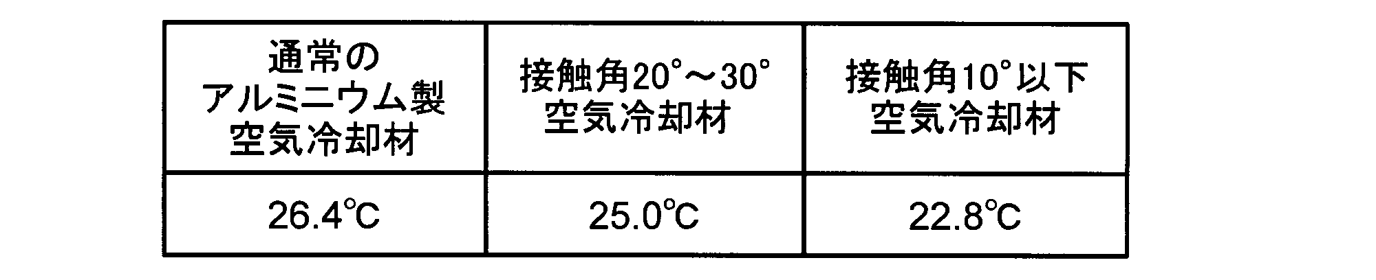
表2によれば、環境温度30℃、湿度40%において、親水性処理を施していない通常のアルミニウム製の空気冷却材11は表面温度が26.4℃であった。接触角が20°~30°である親水性処理を施したアルミニウム製の空気冷却材11は表面温度が25.0℃となった。さらに、接触角が10°以下である親水性処理を施したアルミニウム製の空気冷却材11は表面温度が22.8℃となった。接触角が小さいほど、すなわち親水性の程度が高いほどアルミニウム製の空気冷却材11の温度が低下することが分かった。
親水性処理により、空気冷却材11の表面に水が付着したとき、空気冷却材11の表面と水との境界層が薄くなる。水の気化(蒸発)は水膜表面で起こるため、水膜をより薄くすることで水の気化伝達が促進し、熱伝達効率がさらに向上する。したがって、空気冷却材11をより効率良く冷却することができ、気化式空気調和機1の冷却能力が向上する。
<第4実施形態>
次に、本発明の第4実施形態の気化式空気調和機について、図8を用いて説明する。図8は気化式空気調和機の空気冷却材の配置が冷却温度に及ぼす影響を示すグラフである。なお、この実施形態の基本的な構成は先に説明した第1実施形態と同じであるので、第1実施形態と共通する構成要素には前と同じ符号を付してその説明を省略するものとする。
次に、本発明の第4実施形態の気化式空気調和機について、図8を用いて説明する。図8は気化式空気調和機の空気冷却材の配置が冷却温度に及ぼす影響を示すグラフである。なお、この実施形態の基本的な構成は先に説明した第1実施形態と同じであるので、第1実施形態と共通する構成要素には前と同じ符号を付してその説明を省略するものとする。
第4実施形態の気化式空気調和機1では、複数の空気冷却材11が互いに略平行に配置される。この気化式空気調和機1及び比較例の気化式空気調和機に対して冷却温度の違いを検証した結果を図8に示す。
第4実施形態の気化式空気調和機1に対する比較例の気化式空気調和機は複数の空気冷却材が互いに平行に配置されず(非平行配置)、間隔に狭い場所や広い場所が存在する。図8の縦軸は環境温度との温度差(環境温度に対する空気の冷却温度)(℃)を示し、横軸は空気冷却材の吹出口からの距離(cm)を示す。第4実施形態の気化式空気調和機1及び比較例の気化式空気調和機はともに空気冷却材11の直径が100mmである。
図8によれば、複数の空気冷却材が互いに平行ではない比較例の気化式空気調和機の空気の冷却温度は吹出口において3.2℃であった。一方、複数の空気冷却材11を互いに平行に配置した第4実施形態の気化式空気調和機1の空気の冷却温度は吹出口4において4.5℃であり、高い冷却性能を示している。
複数の空気冷却材が互いに平行ではない場合、隣り合う空気冷却材の間の空気が均一に流通しない。これにより、空気冷却材の間隔が広い場所は風量が多くなり、空気冷却材の間隔が狭い場所は風量が少なくなる。特に、風量が多い場所では熱交換効率が悪くなる。
一方、第4実施形態の気化式空気調和機1のように空気冷却材11を平行に配置することにより、隣り合う空気冷却材11の間の空気の流れを均一にすることができる。したがって、複数の空気冷却材が互いに平行ではない比較例の気化式空気調和機と比較して効果的に空気が冷却され、冷却効率が向上する。
<第5実施形態>
次に、本発明の第5実施形態の気化式空気調和機について、図9を用いて説明する。図9は気化式空気調和機の空気冷却材の直径に対する浸漬深さが空気冷却材の水の付着面積に及ぼす影響を示すグラフである。なお、この実施形態の基本的な構成は先に説明した第1実施形態と同じであるので、第1実施形態と共通する構成要素には前と同じ符号を付してその説明を省略するものとする。
次に、本発明の第5実施形態の気化式空気調和機について、図9を用いて説明する。図9は気化式空気調和機の空気冷却材の直径に対する浸漬深さが空気冷却材の水の付着面積に及ぼす影響を示すグラフである。なお、この実施形態の基本的な構成は先に説明した第1実施形態と同じであるので、第1実施形態と共通する構成要素には前と同じ符号を付してその説明を省略するものとする。
第5実施形態の気化式空気調和機1では、空気冷却材11の貯水部30の水に浸漬している表面積が空気冷却材11の表面積全体の5%~50%である。ここでは、円形の板状をなす空気冷却材11の直径に対する浸漬深さが空気流通路5の空気流通空間に対して露出する空気冷却材11の表面積、すなわち空気冷却材11の水の付着面積に及ぼす影響を評価し、その結果を図9に示す。
円形の板状をなす空気冷却材11は回転するため、全周囲に貯水部30の水が付着する。しかしながら、空気冷却材11の水に浸漬している箇所は空気が流れないため、浸漬領域を差し引いた面積が最大になれば良い。図9の縦軸は空気冷却材11の水の付着面積(mm2)を示し、横軸は空気冷却材11の直径に対する浸漬深さの割合(%)を示す。空気冷却材11の直径については80mm~130mmの10mm刻みで検証した。
空気冷却材11の直径をd(mm)とし、空気冷却材11の直径に対する浸漬深さの割合をz(%)とした場合、空気冷却材11の水が付着して浸漬してない領域は次に示す式で表される。
π(d/2)2-π(d/2-z/100×d)2-[π(d/2)2×2cos-1[(d/2-z/100×d)/(d/2)]/2π-2×d/2×sin[cos-1((d/2-z/100×d)/(d/2))]×(d/2-z/100×d)/2]
この式による計算結果を図9として示す。図9によれば、空気冷却材11がいずれの直径であっても、直径に対する浸漬深さが35%であれば空気冷却材11の水の付着面積が最大値となる。
ここで、先に図8を用いて説明した第4実施形態の気化式空気調和機1は空気冷却材11の直径に対する浸漬深さが25%であり、空気冷却材11の間隔が6mmのときの結果であり、最大で4.5℃程度の冷却温度であった。先に図4を用いて説明した従来例の気化式空気調和機100が0.7℃程度の冷却温度であったことと比較すると、気化量が最大で6.4倍程度になっていることに相当する。すなわち、従来例の気化式空気調和機100の蒸発ネット105における水の付着面積は第5実施形態の気化式空気調和機1の1/6.4程度であると考えられる。
一方、図9によれば、空気冷却材11の直径に対する浸漬深さが25%である場合の空気冷却材11の水の付着面積は空気冷却材11の表面積全体の55%程度である。従来例の気化式空気調和機100の蒸発ネット105における水の付着面積は第5実施形態の気化式空気調和機1の1/6.4程度であるとすれば、空気冷却材11の表面積全体の8.5%程度に相当する。
空気冷却材11の間隔を3mm程度まで狭くすれば、冷却温度をさらに低下させることができる。この場合、図8を用いて説明した第4実施形態の気化式空気調和機の空気冷却材11の間隔が6mmのときの結果である最大4.5℃程度の冷却温度に対して1.6倍程度冷却温度をさらに低下させることが実現できる可能性がある。そして、空気冷却材11の水の付着面積である空気冷却材11の表面積全体の8.5%を1.6で割ると5%程度になる。これにより、空気冷却材11の水の付着面積が空気冷却材11の表面積全体の5%であれば、従来例の気化式空気調和機100と同等レベルの冷却性能が得られると考えられる。
以上のことから、空気冷却材11の水の付着面積、すなわち空気冷却材11の貯水部30の水に浸漬している表面積が空気冷却材11の表面積全体の5%以上、すなわち水位として空気冷却材11の直径の1.5%以上の深さで浸漬していることが好ましい。一方、空気冷却材11の水の付着面積、すなわち空気冷却材11の貯水部30の水に浸漬している表面積が空気冷却材11の表面積全体の50%を超えると、軸12の箇所から本体筐体2の外部に水が漏洩してしまう。したがって、空気冷却材11の水の付着面積、すなわち空気冷却材11の貯水部30の水に浸漬している表面積は空気冷却材11の表面積全体の5%~50%が好ましい。
<第6実施形態>
次に、本発明の第6実施形態の気化式空気調和機について、図10を用いて説明する。図10は気化式空気調和機の空気冷却材の説明図であって空気流通方向と直角をなす方向から見た図である。なお、この実施形態の基本的な構成は先に説明した第1実施形態と同じであるので、第1実施形態と共通する構成要素には前と同じ符号を付してその説明を省略するものとする。
次に、本発明の第6実施形態の気化式空気調和機について、図10を用いて説明する。図10は気化式空気調和機の空気冷却材の説明図であって空気流通方向と直角をなす方向から見た図である。なお、この実施形態の基本的な構成は先に説明した第1実施形態と同じであるので、第1実施形態と共通する構成要素には前と同じ符号を付してその説明を省略するものとする。
第6実施形態の気化式空気調和機1は空気冷却材14が板状の金属材料、例えばアルミニウムからなる。そして、図10に示すように、そのアルミニウムからなる空気冷却材14の表面に礫状体の凹凸部15を設けた。空気冷却材14の表面の凹凸部15はエンボス加工や多孔質加工(多孔質材料を用いる場合も含む)、梨地加工により設けても良い。この構成によれば、空気冷却材14の水及び空気に対する接触面積はその体積の割に非常に大きくなり冷却効率が向上する。
表面に親水性処理を施したアルミニウムからなる空気冷却材を用いた場合、継続して水が気化されるために表面にスケールが付着する。このスケールは親水性の多孔質膜として、性能の向上に貢献する。従来のフィルタ式はフィルタ表面の細かな凹凸によって性能を上げようとしているためにスケールによって目詰まりがおきてしまい、性能が悪化していた。本実施形態の方法であれば、気化式空気調和機を使用するたびに空気冷却材の表面積を大きくすることができ、性能を高めることができる。
凹凸部15は細かければ細かいほど好ましい。凹凸部15により毛細管現象が強く働き、空気冷却材14に付着した水が細部まで導かれ水膜がより薄化する。これにより、水の気化(蒸発)が一層進行し易くなり、気化冷却が促進する。また、空気との接触面が大きくなることや空気流をかき乱すことで空気の冷却を促進する効果がある。なお、凹凸部15に代えて凹部または凸部の一方であっても良い。
<第7実施形態>
次に、本発明の第7実施形態の気化式空気調和機について説明する。なお、この実施形態の基本的な構成は先に説明した第1実施形態と同じであるので、第1実施形態と共通する構成要素には前と同じ符号を付してその説明を省略するものとする。
次に、本発明の第7実施形態の気化式空気調和機について説明する。なお、この実施形態の基本的な構成は先に説明した第1実施形態と同じであるので、第1実施形態と共通する構成要素には前と同じ符号を付してその説明を省略するものとする。
上記実施形態の気化式空気調和機1は空気冷却材11の表面に付着する水が気化(蒸発)することで気温が低下する効果を利用したものである。同時に、水の気化により冷却された空気冷却材11と下部に配置された貯水部30の内部の水との間で熱交換をさせて、水も併せて冷却する効果を有している。このようにして冷却された水が蓄冷材として機能するようになれば、空気冷却材11の回転を停止させて気化量を少なくしても、空気冷却材11の熱伝導率が比較的高ければ、一定時間空気を冷却することができる。これにより、消費電力の低減、加湿量の調整などが実現可能である。
また、空気冷却材11の熱伝導率としては、50W/m・k以上であることが好ましい。例えば、気温28℃、湿度45%の環境で上記実施形態の気化式空気調和機1を使用すると、水の温度は約20℃程度になる。例えば、空気冷却材11をアルミニウムで構成して一枚当たりの熱伝導率が237W/m・kであれば、空気と水温との温度差8kで、空気流通路5の中心部となる2cmまで伝達させると、空気冷却材11の一枚当たりの冷却能力は次に示す式で表される。
237[W/m・k]×(空気冷却材11の断面積:10cm×0.02cm)
/(到達距離:2cm)/100[m]×8[k]=1.9W
/(到達距離:2cm)/100[m]×8[k]=1.9W
このようにして、空気冷却材11の一枚当たりの冷却能力は1.9Wとなる。空気冷却材11の枚数を15枚にすれば、気化式空気調和機1は約29Wの冷却能力を有することになる。
これに気化成分が加わるが、気化量が1時間で130cc(実験結果)であれば、冷却能力は81Wとなる。単純に水を気化するだけではその気化量に大きく影響するが、熱伝導率が比較的高い材料を用いると、冷却された水自体が空気の冷却に寄与することになる。これにより、空気冷却材11の熱伝導率が30W/m・k以上であれば、水の気化による冷却能力に加えて熱伝導による熱量が4%以上となり、冷却能力の向上に有効に寄与できるようになると考えられる。したがって、第7実施形態の気化式空気調和機1は空気冷却材11を構成する金属材料の熱伝導率が30W/m・k以上である。
また、空気冷却材11の比熱は0.1J/g・℃以上、2.0J/g・℃以下であることが好ましい。空気冷却材11の比熱が低過ぎると、気化熱で冷却されても、すぐに外部の空気で暖められてしまう。空気冷却材11の比熱が高過ぎると、気化熱で熱を奪われても、空気冷却材11自体が冷却され難い。したがって、第7実施形態の気化式空気調和機1は空気冷却材11を構成する金属材料の比熱が0.1J/g・℃以上、2.0J/g・℃以下である。
<第8実施形態>
次に、本発明の第8実施形態の気化式空気調和機について、図11を用いて説明する。図11は気化式空気調和機の概略垂直断面正面図である。なお、この実施形態の基本的な構成は先に説明した第1実施形態と同じであるので、第1実施形態と共通する構成要素には前と同じ符号を付してその説明を省略するものとする。
次に、本発明の第8実施形態の気化式空気調和機について、図11を用いて説明する。図11は気化式空気調和機の概略垂直断面正面図である。なお、この実施形態の基本的な構成は先に説明した第1実施形態と同じであるので、第1実施形態と共通する構成要素には前と同じ符号を付してその説明を省略するものとする。
第8実施形態の気化式空気調和機1は、図11に示すように給水容器40を備える。給水容器40は水Wを収容して貯水部30に対して着脱可能であるとともに、給水可能である。
給水容器40は縦長の形態をなし、給水口41を下にしてその長手方向が略鉛直をなすように立てて配置される。給水口41は貯水容器31に連通し、給水容器40の内部の水Wを貯水容器31の内部の水Wとして補給する。給水容器40の内部の水Wは重力の作用により貯水容器31に補給される。給水容器40は貯水容器31と連通する給水口41以外が密閉されている。
給水容器40は給水口41の箇所に弁42を備える。弁42は、例えばバネを用いた弁で構成され、トリチェリの原理によって自動的に貯水容器31の水位を一定に調節する。
水Wが気化して貯水容器31の水位が下がると、空気が密閉された給水容器40の内部に流れ込み、給水容器40から水Wが排出される。給水容器40の水位が貯水容器31の水位と同程度になる、すなわち気化式空気調和機1の内部の水Wがほぼ空になれば、給水容器40に水を入れて再度気化式空気調和機1に装着すれば良い。給水容器40を気化式空気調和機1から取り外すとき、弁42が閉じるので、水Wが漏洩することはほとんどない。
このようにして気化式空気調和機1の水位を一定時間安定させることができ、高い冷却性能を維持することが可能である。
<第9実施形態>
次に、本発明の第9実施形態の気化式空気調和機について、図12~図15を用いて説明する。図12は気化式空気調和機の概略垂直断面側面図である。図13及び図14は気化式空気調和機の貯水部の蓋の斜視図及び上面図である。図15は図12に示す貯水部の蓋のXV-XV線における水平断面図である。なお、この実施形態の基本的な構成は先に説明した第1実施形態と同じであるので、第1実施形態と共通する構成要素には前と同じ符号を付してその説明を省略するものとする。
次に、本発明の第9実施形態の気化式空気調和機について、図12~図15を用いて説明する。図12は気化式空気調和機の概略垂直断面側面図である。図13及び図14は気化式空気調和機の貯水部の蓋の斜視図及び上面図である。図15は図12に示す貯水部の蓋のXV-XV線における水平断面図である。なお、この実施形態の基本的な構成は先に説明した第1実施形態と同じであるので、第1実施形態と共通する構成要素には前と同じ符号を付してその説明を省略するものとする。
第9実施形態の気化式空気調和機1は、図12に示すように貯水部30が蓋32を備える。蓋32は貯水容器31の上面開口を全体的に閉塞する。蓋32には、図12及び図13に示すように板状部32a及び収容部32bが設けられる。
蓋32の板状部32aは長方形状をなし、その平面部が貯水容器31の水面を覆うように配置される。板状部32aは、図13及び図14に示すように長方形のスリット状をなして上下方向に貫通する複数の挿通孔32cを備える。挿通孔32cは複数の空気冷却材11に対応した数量が各々、空気冷却材11に対応した位置に設けられる。挿通孔32cには各々一枚ずつ空気冷却材11の下側の一部が挿通する。
蓋32の収容部32bは、図12及び図13に示すように両端を閉塞した円筒を横倒しにして略水平に切断した下側の一部からなる形状であって、その切断面に表れる矩形開口を塞ぐように板状部32aの下面に取り付けられる。収容部32bはすべての挿通孔32cの板状部32aの下面側の出入り口を覆う。収容部32bを形成する円筒は、その軸線が円形の板状をなす空気冷却材11の軸線と一致し、その直径が空気冷却材11の直径より大きい。これにより、収容部32bは挿通孔32cを通って板状部32aの下側に出現する空気冷却材11の一部を覆うように収容する。
収容部32bは、図12及び図15に示すようにその最下部に複数の通水孔32dを備える。通水孔32dは収容部32bの内側から外側まで貫通するよう設けられる。貯水容器31が貯留する水Wは通水孔32dを通って収容部32bの外部と内部との間を流通する。通水孔32dの位置は収容部32bの最下部に限定されるわけではなく、収容部32bの他の箇所であっても良い。また、通水孔32dの数量も図15に示した数量に限定されるわけではない。
貯水部30に蓋32を設けることにより、気化式空気調和機1が転倒した際の貯水容器31が貯留する水Wの漏洩が抑制される。したがって、気化式空気調和機1の安全性が向上する。
<第10実施形態>
次に、本発明の第10実施形態の気化式空気調和機について、図16を用いて説明する。図16は気化式空気調和機の冷却部及び貯水部を示す概略垂直断面正面図である。なお、この実施形態の基本的な構成は先に説明した第9実施形態と同じであるので、第9実施形態と共通する構成要素には前と同じ符号を付してその説明を省略するものとする。
次に、本発明の第10実施形態の気化式空気調和機について、図16を用いて説明する。図16は気化式空気調和機の冷却部及び貯水部を示す概略垂直断面正面図である。なお、この実施形態の基本的な構成は先に説明した第9実施形態と同じであるので、第9実施形態と共通する構成要素には前と同じ符号を付してその説明を省略するものとする。
第10実施形態の気化式空気調和機1は、図16に示すように蓋32が収容部32bの内部に仕切り32eを備える。仕切り32eは収容部32bの外形をなす円筒の軸線と直交する収容部32bの垂直断面形状、すなわち図16の紙面奥行き方向を平行をなす収容部32bの垂直断面形状と同形状の板状をなす。仕切り32eは複数が、空気冷却材11の平面部11aと平行にして、隣り合う空気冷却材11の間各々に配置される。挿通孔32cは隣り合う仕切り32eの間若しくは収容部32bの垂直壁32fと仕切り32eとの間に位置する。
複数の空気冷却材11は各々、下側の一部が隣り合う仕切り32eと収容部32bの円筒壁との間若しくは収容部32bの垂直壁32fと仕切り32eと収容部32bの円筒壁との間に形成された収容部32b内部の小領域32gに収容される。この収容部32bの小領域32g各々には、少なくとも1個の通水孔32dが設けられる。貯水容器31が貯留する水Wは通水孔32dを通って収容部32bの小領域32g各々の外部と内部との間を流通する。
なお、空気冷却材11と仕切り32eとの間隔は、特に制限はないが1.0mm~5.0mm程度に設定されることが好ましい。
貯水部30に蓋32を設け、且つ蓋32の収容部32bの内部に仕切り32eを設けることにより、収容部32b(小領域32g)に含まれる水Wの量が空気冷却材11にとって必要な量に抑制される。これにより、気化式空気調和機1が転倒した際の貯水容器31が貯留する水Wの漏洩が、第9実施形態の気化式空気調和機1に対してさらに抑制される。したがって、気化式空気調和機1の安全性がより一層向上する。
上記のように、本実施形態の気化式空気調和機1は、空気の吸込口3及び吹出口4を開口する本体筐体2と、吸込口3と吹出口4とを連通させる空気流通路5と、空気流通路5に気流を発生させる送風ファン6と、送風ファン6による空気流通方向と略平行をなす平面部11aを有して空気流通方向と略直角をなす方向に平面部11aが対向し合うように所定間隔をあけて並べて配置された複数の円形の板状の空気冷却材11と、空気流通方向と略直角をなす方向に延びる軸線を中心として空気冷却材11を回転させる回転機構20と、を備える。
この構成によれば、送風ファン6及び空気冷却材11を回転させると、複数の板状をなす空気冷却材11の間をスムーズに空気を流通させることができる。すなわち、従来技術で見られたフィルタケースのように空気流通路を塞ぐことがない。そして、空気冷却材11を略円形の板状にすることで表面積をより広くすることができ、気化量が増加し、それに伴う冷却温度も大きくなる。また、空気冷却材11が多角形、特に六角形または八角形であれば、一枚の板からより多くの空気冷却材11を形成することができるので、材料の利用効率が高くなる。
また、空気冷却材11を金属材料またはセラミック材料で構成することにより、送風によって熱交換され易い箇所、すなわち気流の当たり易い箇所で局所的に水が気化して冷却されたとしても、当該箇所の温度低下は緩和される。従来の蒸発ネットや気化フィルタであれば、送風によって熱交換され易い箇所での水の気化量は気化による温度低下とともに減少してしまう。しかしながら、空気冷却材11に金属材料を用いることで温度分布が平準化され易いため、気流が当たり易い箇所で高い気化量を維持することができる。
さらに、空気冷却材11を金属材料で構成すると、表面に付着する水が気温より低い場合に気化量が少なくなっても、金属から水に対して熱放出され易くなる。さらに、空気冷却材11をより熱伝達率が高い金属材料またはセラミック材料で構成すると、水が気化する際の潜熱の伝達効率が上昇し、空気冷却材11をより効率良く冷却することが可能である。これらのことから、気化式空気調和機1の冷却効率を向上させることが可能である。
また、空気冷却材11は金属元素を多く含んだ材料で構成される。具体的に言えば、特にエアコン用に使用されるアルミニウムであることが望ましい。アルミニウムであれば、風によるバタつきなどを抑制することができる。さらに、空気冷却材11は金属材料で構成されるので、カビなどが発生し難い。これにより、従来の課題を一気に解決できる。
また、気化式空気調和機1は水Wを貯留する貯水部30を備え、空気冷却材11の一部が貯水部30の水Wと接触しているので、回転機構20による回転で、空気冷却材11の平面部11aを広範囲にわたって水Wと接触させることができる。さらに、空気冷却材11を比較的低速で回転させると、空気冷却材11に継続的に水Wが付着する。空気冷却材11に付着する水の気化熱により、空気冷却材11自身やその周囲の空気を継続して冷却することができる。冷却された空気冷却材11はその周囲を流通する空気との間で熱交換を行い、空気を冷却することが可能である。
また、空気流通路5は空気流通方向が冷却部10において下方の貯水部30の水Wに接近するように湾曲して延びて吸込口3と吹出口4とが略対向するので、圧力損失を低減することができる。そして、強い風を冷却部10に当てることができ、さらに吹出口4の風速を高めることが可能である。なお、空気流通路5を直線状に延びるように形成しても良い。
また、空気冷却材11は吹出口4の空気流通方向上流側に隣接して配置される。この構成によれば、より冷たい空気を本体筐体2の外部に吹き出すことが可能である。
また、空気冷却材11を金属材料と保水性を有する高分子材料からなるよう形成すると、空気冷却材11の表面に水が滞留する作用を高めることができる。したがって、空気冷却材11をより効率良く冷却することができ、気化式空気調和機1の冷却能力を向上させることが可能である。
また、気化式空気調和機1は空気冷却材11の表面に親水性処理を施したので、空気冷却材11の表面に水が付着したとき、空気冷却材11の表面と水との境界層が薄くなる。水の気化(蒸発)は水膜表面で起こるため、水膜をより薄くすることで水の気化伝達が促進され、熱伝達効率をさらに向上させることができる。したがって、空気冷却材11をより効率良く冷却することができ、気化式空気調和機1の冷却効率を向上させることが可能である。
なお、空気冷却材11をアルミニウムで構成することにより、薄板であるにもかかわらず熱伝導性が高くて形状が保持し易い。また、空気冷却材11の表面に親水性処理を施したので、水を薄膜状に保持させることができる。また、室内機向けのエアコンフィンであれば親水性塗膜の中に抗菌剤も含まれているため、カビの心配も軽減されて悪臭が発生し難い。
さらに、空気冷却材11の表面への親水性処理により、垂直に立てて配置された空気冷却材11の表面に付着させた水をより長く留まらせることが可能である。したがって、空気冷却材11をより効率良く冷却することができ、気化式空気調和機1の冷却効率を向上させることが可能である。
また、空気冷却材11はその一部が空気流通路5の内側に位置し、空気流通路5における回転機構20による回転に基づく周縁部の貯水部30から最も離れた箇所の移動方向が空気流通方向と略一致する。これにより、回転機構20による回転で、空気流通路5の外側に位置して貯水部30の水Wに浸かる空気冷却材11の浸漬部分のうち回転方向最下流部が吸込口3に最も近い箇所で空気流通路5の内側に出現する。したがって、空気流通路5に流入した冷却前の乾燥した温かい空気を最初に、空気冷却材11の空気流通路5の内側に位置する部分のうち水が最も多く付着する箇所に接触させることができる。その結果、水の気化量を増加させることができ、冷却効率を向上させることが可能である。
さらに、空気冷却材11の一部は、貯水部30において水中に浸漬しているので、水温と同程度の温度になる。続いて、空気流通路5の内側に出現した空気冷却材11の一部は水の気化により水温と同程度の温度からさらに温度が低下し、空気流通方向の下流、すなわち吹出口4の近傍でより一層温度低下量が大きくなる。また、吹出口4の近傍では水の気化により空気の湿度も比較的高くなる。続いて、空気冷却材11の空気流通路5の内側に位置する一部は貯水部30の水Wに浸かり、水温と同程度の温度になる。このとき、空気冷却材11の温度が水温より低くなっていると、貯水部30の水Wそのものを冷却し、空気冷却材11は熱交換されて水温近くまで温度上昇する。
水の気化量を増加させるためには、水及び空気の温度が比較的高く、空気の湿度が比較的低いという条件が効果的である。したがって、上記実施形態によれば、空気流通路5に流入した冷却前の乾燥した温かい空気を最初に、空気冷却材11の空気流通路5の内側に位置する部分のうち比較的温度が高い水が多く付着する箇所に接触させることができる。その結果、水の気化量を増加させることができ、冷却効率を向上させることが可能である。
また、空気冷却材11の回転速度を、吹出口4側の空気冷却材11の部位において概ね気化完了直前程度の速度とすれば、水の気化速度が最も高くなる。空気冷却材11の表面の水膜は気化完了直前において最も薄く、空気冷却材11の表面の凹凸の影響が顕著に表れるようにすることができ、冷却性能が最も高くなる。
また、回転機構20が周辺温度及び周辺湿度の少なくとも一方に基づき空気冷却材11の回転速度を変更することにしても良い。これにより、冷却性能が一層高くなる。例えば、水の気化速度は高温または乾燥環境では速く、低温または多湿環境では遅い。したがって、高温または乾燥環境において空気冷却材11の回転速度をより速くすれば冷却効率が一層高くなる。一例として、気温28℃、湿度45%程度の環境であれば、数rpm程度において空気冷却材11の一部が乾燥し始める傾向にあり、冷却性能が最も高くなる。
なお、空気冷却材11の回転方向は、空気流通路5における回転機構20による回転に基づく周縁部の貯水部30から最も離れた箇所の移動方向が空気流通方向と略一致していることが最も好ましい。
空気冷却材11の回転に関して、例えば回転機構20のモータ21に交流で駆動するシンクロナスモータを使用すると、回転方向を選択することができなくなる。しかしながらその一方で、回路部品等が必要なくなるというメリットがあり、回転方向が逆方向でも一定の性能を有しているため、モータ21にシンクロナスモータを使用することにしても良い。
また、円形の板状をなす空気冷却材11が水に接触している領域が、空気冷却材11の直径の10%~50%で安定して維持できるようにすることが好ましい。より好ましくは、空気冷却材11の直径の35%程度である。
円形の板状をなす空気冷却材11は回転するため、全周囲に貯水部30の水が付着する。しかしながら、空気冷却材11の水に浸漬している箇所は空気が流れないため、浸漬領域を差し引いた面積が最大になれば良い。このことについて検討を重ねた結果、空気冷却材11の水の付着面積、すなわち空気冷却材11の貯水部30の水に浸漬している表面積は空気冷却材11の表面積全体の5%~50%が好ましい。空気冷却材11の水の付着面積、すなわち空気冷却材11の貯水部30の水に浸漬している表面積が50%を超えると、軸12の箇所から本体筐体2の外部に水が漏洩する。空気冷却材11の水の付着面積、すなわち空気冷却材11の貯水部30の水に浸漬している表面積が10%を下回ると、冷却性能が半分以下に低下する。
また、複数の空気冷却材11は互いに略平行に配置されるので、隣り合う空気冷却材11の間の空気の流れを均一にすることができる。したがって、複数の空気冷却材が互いに平行ではない従来例の気化式空気調和機と比較して効果的に空気を冷却することができ、冷却効率を向上させることが可能である。
また、金属材料からなる空気冷却材14の表面に凹凸部15を形成したので、空気冷却材14の水及び空気に対する接触面積をその体積の割に非常に大きくすることができる。したがって、空気冷却材14をより効率良く冷却することができ、気化式空気調和機1の冷却能力を向上させることが可能である。
また、空気冷却材11を構成する金属材料の熱伝導率が30W/m・k以上であるので、水の気化による冷却能力に加えて熱伝導による熱量を4%以上にすることができる。これにより、気化式空気調和機1の冷却能力の向上を図ることが可能である。
また、気化式空気調和機1は、空気冷却材11を構成する金属材料の比熱が0.1J/g・℃以上、2.0J/g・℃以下である。空気冷却材11の比熱が低過ぎると、気化熱で冷却されても、すぐに外部の空気で暖められてしまう。空気冷却材11の比熱が高過ぎると、気化熱で熱を奪われても、空気冷却材11自体が冷却され難い。したがって、上記実施形態の気化式空気調和機1はこれらの不具合を解消することが可能である。
また、気化式空気調和機1は水Wを収容して貯水部30に対して着脱可能であるとともに給水可能な給水容器40を備える。これにより、気化式空気調和機1に対する給水が容易になるとともに、気化式空気調和機1の水位を一定時間安定させることができる。したがって、気化式空気調和機1は高い冷却性能を維持することが可能である。
また、給水容器40は貯水部30と連通する給水口41以外が密閉されている。これにより、給水口41以外の箇所から水Wが漏洩することを防止することができる。
また、給水容器40は給水口41の箇所に弁42を備える。弁42を、例えばバネを用いた弁で構成すると、トリチェリの原理によって自動的に貯水容器31の水位を一定に調節することができる。さらに、給水容器40を気化式空気調和機1から取り外すとき、弁42が閉じるので、水Wの漏洩を抑制することが可能である。
また、気化式空気調和機1は、貯水部30が水を貯留する貯水容器31と、貯水容器31の上面開口を閉塞する蓋32と、蓋32に設けられ空気冷却材11が挿通する挿通孔32cと、蓋32に設けられ空気冷却材11の一部を収容する収容部32bと、収容部32bに設けられ貯水容器31が貯留する水Wが流通する通水孔32dと、を備える。これにより、気化式空気調和機1が転倒した際の貯水容器31が貯留する水Wの漏洩を抑制することができる。したがって、気化式空気調和機1の安全性が向上させることが可能である。
そして、本発明の上記実施形態の構成によれば、水の気化熱を利用して空気を冷却するにあたって、冷却効率の向上が図られた気化式空気調和機1を提供することができる。
以上、本発明の実施形態につき説明したが、本発明の範囲はこれに限定されるものではなく、発明の主旨を逸脱しない範囲で種々の変更を加えて実施することができる。
例えば、本発明の気化式空気調和機は、加湿器など、冷却機能と他の機能を備えた機器においても適用可能であることは勿論である。
本発明は気化式空気調和機において利用可能である。
1 気化式空気調和機
2 本体筐体
3 吸込口
4 吹出口
5 空気流通路
6 送風ファン
10 冷却部
11 空気冷却材
12 軸
13 親水性薄膜
14 空気冷却材
15 凹凸部
20 回転機構
30 貯水部
31 貯水容器
32 蓋
32b 収容部
32c 挿通孔
32d 通水孔
40 給水容器
41 給水口
42 弁
2 本体筐体
3 吸込口
4 吹出口
5 空気流通路
6 送風ファン
10 冷却部
11 空気冷却材
12 軸
13 親水性薄膜
14 空気冷却材
15 凹凸部
20 回転機構
30 貯水部
31 貯水容器
32 蓋
32b 収容部
32c 挿通孔
32d 通水孔
40 給水容器
41 給水口
42 弁
Claims (18)
- 空気の吸込口及び吹出口を開口する本体筐体と、
前記吸込口と前記吹出口とを連通させる空気流通路と、
前記空気流通路に気流を発生させる送風ファンと、
前記送風ファンによる空気流通方向と略平行をなす平面部を有して前記空気流通方向と略直角をなす方向に前記平面部が対向し合うように所定間隔をあけて並べて配置された複数の多角形または略円形の板状の金属材料またはセラミック材料からなる空気冷却材と、
前記空気流通方向と略直角をなす方向に延びる軸線を中心として前記空気冷却材を回転させる回転機構と、
水または水を含む液体を貯留する貯水部と、
を備え、
前記空気冷却材はその一部が前記貯水部の水または水を含む液体と接触することを特徴とする気化式空気調和機。 - 前記空気流通路は空気流通方向が直線状に延びて、または湾曲して延びて前記吸込口と前記吹出口とが略対向することを特徴とする請求項1に記載の気化式空気調和機。
- 前記空気冷却材は前記吹出口の空気流通方向上流側に隣接して配置されることを特徴とする請求項1または請求項2に記載の気化式空気調和機。
- 前記空気冷却材は金属材料と保水性を有する高分子材料からなることを特徴とする請求項1~請求項3のいずれかに記載の気化式空気調和機。
- 前記空気冷却材を構成する金属材料の表面に親水性処理を施したことを特徴とする請求項1~請求項4のいずれかに記載の気化式空気調和機。
- 前記空気冷却材はその一部が前記空気流通路に位置し、前記空気流通路における前記回転機構による回転に基づく周縁部の前記貯水部から最も離れた箇所の移動方向が前記空気流通方向と略一致し、その回転速度が前記空気冷却材の表面に付着する水の一部が気化して前記空気冷却材の表面の一部が露出する程度の速度であることを特徴とする請求項1~請求項5のいずれかに記載の気化式空気調和機。
- 前記空気冷却材はその一部が前記空気流通路に位置し、前記空気流通路における前記回転機構による回転に基づく周縁部の、前記貯水部から最も離れた箇所の移動方向が前記空気流通方向に対して逆方向であることを特徴とする請求項1~請求項6のいずれかに記載の気化式空気調和機。
- 前記空気冷却材の、前記貯水部が貯留する水または水を含む液体に浸漬している表面積が前記空気冷却材の表面積全体の5%~50%であることを特徴とする請求項1~請求項7のいずれかに記載の気化式空気調和機。
- 複数の前記空気冷却材は互いに略平行に配置されることを特徴とする請求項1~請求項8のいずれかに記載の気化式空気調和機。
- 前記空気冷却材はその表面に凹部及び凸部の少なくとも一方を有することを特徴とする請求項1~請求項9のいずれかに記載の気化式空気調和機。
- 前記空気冷却材を構成する金属材料の熱伝導率が30W/m・k以上であることを特徴とする請求項1~請求項10のいずれかに記載の気化式空気調和機。
- 前記空気冷却材を構成する金属材料の比熱が0.1J/g・℃以上、2.0J/g・℃以下であることを特徴とする請求項1~請求項11のいずれかに記載の気化式空気調和機。
- 水または水を含む液体を収容して前記貯水部に対して着脱可能であるとともに給水可能な給水容器を備えることを特徴とする請求項1~請求項12のいずれかに記載の気化式空気調和機。
- 前記給水容器は前記貯水部と連通する箇所以外が密閉されていることを特徴とする請求項1~請求項13のいずれかに記載の気化式空気調和機。
- 前記給水容器は前記貯水部と連通する箇所に弁を備えることを特徴とする請求項1~請求項14のいずれかに記載の気化式空気調和機。
- 前記回転機構は前記空気冷却材の回転速度及び回転方向が変更可能であることを特徴とする請求項1~請求項15のいずれかに記載の気化式空気調和機。
- 前記回転機構は周辺温度及び周辺湿度の少なくとも一方に基づき前記空気冷却材の回転速度を変更することを特徴とする請求項1~請求項16のいずれかに記載の気化式空気調和機。
- 前記貯水部は前記空気冷却材の表面に対して水が流通する通水孔を備えることを特徴とする請求項1~請求項17のいずれかに記載の気化式空気調和機。
Applications Claiming Priority (4)
| Application Number | Priority Date | Filing Date | Title |
|---|---|---|---|
| JP2013-230989 | 2013-11-07 | ||
| JP2013230989 | 2013-11-07 | ||
| JP2014-036980 | 2014-02-27 | ||
| JP2014036980A JP2015111023A (ja) | 2013-11-07 | 2014-02-27 | 気化式空気調和機 |
Publications (1)
| Publication Number | Publication Date |
|---|---|
| WO2015068445A1 true WO2015068445A1 (ja) | 2015-05-14 |
Family
ID=53041229
Family Applications (1)
| Application Number | Title | Priority Date | Filing Date |
|---|---|---|---|
| PCT/JP2014/072082 Ceased WO2015068445A1 (ja) | 2013-11-07 | 2014-08-25 | 気化式空気調和機 |
Country Status (2)
| Country | Link |
|---|---|
| JP (1) | JP2015111023A (ja) |
| WO (1) | WO2015068445A1 (ja) |
Cited By (2)
| Publication number | Priority date | Publication date | Assignee | Title |
|---|---|---|---|---|
| CN113339366A (zh) * | 2021-06-30 | 2021-09-03 | 中国科学院广州能源研究所 | 一种整体式多孔陶瓷填料 |
| EP3891440A4 (en) * | 2018-12-06 | 2022-08-17 | Intex Holdings Pty Ltd | DEVICE FOR REMOVING WATER FROM A FLUID |
Families Citing this family (1)
| Publication number | Priority date | Publication date | Assignee | Title |
|---|---|---|---|---|
| JP2022156152A (ja) * | 2021-03-31 | 2022-10-14 | セイコーエプソン株式会社 | 加湿装置および繊維体処理装置 |
Citations (7)
| Publication number | Priority date | Publication date | Assignee | Title |
|---|---|---|---|---|
| JPS6231215U (ja) * | 1985-08-09 | 1987-02-25 | ||
| JPS62131137A (ja) * | 1985-12-03 | 1987-06-13 | Mitsubishi Electric Corp | 湿度調整器 |
| JPH0614822U (ja) * | 1992-07-23 | 1994-02-25 | 石川島芝浦機械株式会社 | 冷風扇 |
| JP2009168414A (ja) * | 2008-01-21 | 2009-07-30 | Panasonic Corp | 液体微粒化装置とそれを用いたサウナ装置 |
| JP2012063138A (ja) * | 2011-12-28 | 2012-03-29 | Mitsubishi Electric Corp | 加湿装置 |
| JP2012107860A (ja) * | 2012-02-28 | 2012-06-07 | Mitsubishi Electric Corp | 加湿装置 |
| JP2013072585A (ja) * | 2011-09-27 | 2013-04-22 | Sharp Corp | 加湿装置 |
-
2014
- 2014-02-27 JP JP2014036980A patent/JP2015111023A/ja active Pending
- 2014-08-25 WO PCT/JP2014/072082 patent/WO2015068445A1/ja not_active Ceased
Patent Citations (7)
| Publication number | Priority date | Publication date | Assignee | Title |
|---|---|---|---|---|
| JPS6231215U (ja) * | 1985-08-09 | 1987-02-25 | ||
| JPS62131137A (ja) * | 1985-12-03 | 1987-06-13 | Mitsubishi Electric Corp | 湿度調整器 |
| JPH0614822U (ja) * | 1992-07-23 | 1994-02-25 | 石川島芝浦機械株式会社 | 冷風扇 |
| JP2009168414A (ja) * | 2008-01-21 | 2009-07-30 | Panasonic Corp | 液体微粒化装置とそれを用いたサウナ装置 |
| JP2013072585A (ja) * | 2011-09-27 | 2013-04-22 | Sharp Corp | 加湿装置 |
| JP2012063138A (ja) * | 2011-12-28 | 2012-03-29 | Mitsubishi Electric Corp | 加湿装置 |
| JP2012107860A (ja) * | 2012-02-28 | 2012-06-07 | Mitsubishi Electric Corp | 加湿装置 |
Cited By (2)
| Publication number | Priority date | Publication date | Assignee | Title |
|---|---|---|---|---|
| EP3891440A4 (en) * | 2018-12-06 | 2022-08-17 | Intex Holdings Pty Ltd | DEVICE FOR REMOVING WATER FROM A FLUID |
| CN113339366A (zh) * | 2021-06-30 | 2021-09-03 | 中国科学院广州能源研究所 | 一种整体式多孔陶瓷填料 |
Also Published As
| Publication number | Publication date |
|---|---|
| JP2015111023A (ja) | 2015-06-18 |
Similar Documents
| Publication | Publication Date | Title |
|---|---|---|
| JP2016020782A (ja) | 気化式空気調和機 | |
| JP4595366B2 (ja) | 加湿装置 | |
| US20170003041A1 (en) | Wall-mounted smart dehumidifier | |
| JP6076553B1 (ja) | 加湿装置及び空気調和機 | |
| JP2018036045A (ja) | 外部温度を上昇させないで殺菌機能を含む除湿装置 | |
| WO2014129027A1 (ja) | 気化式空気調和機 | |
| WO2015068445A1 (ja) | 気化式空気調和機 | |
| JP2014185829A (ja) | 加湿装置、並びに、環境試験装置 | |
| JP2006258308A (ja) | 加湿装置 | |
| JP5057958B2 (ja) | 空気調和機 | |
| CN108819255B (zh) | 一种具有循环风道结构的3d打印机成型室 | |
| JP2015034675A (ja) | 気化式冷却装置 | |
| JP2016055264A (ja) | 除湿装置 | |
| CN114151873B (zh) | 蒸发冷却装置及其控制方法、空调器 | |
| KR101228198B1 (ko) | 에어 컨디셔너 | |
| KR20120017376A (ko) | 공기청정가습기 | |
| CN113551313A (zh) | 空调器及其控制方法、控制装置、计算机可读存储介质 | |
| JP4654839B2 (ja) | 加湿装置 | |
| CN108697280A (zh) | 调温体装置以及具有这种调温体装置的前壁装置 | |
| CN110762637A (zh) | 一种加湿组件、空调冷风机及控制方法 | |
| CN217685770U (zh) | 壁挂式空调室内机 | |
| JP2008275301A (ja) | 冷蔵庫、保冷庫用加湿器 | |
| KR20200001843U (ko) | 냉각장치를 구비한 냉풍기 | |
| CN208332477U (zh) | 一种新型风机盘管 | |
| CN218650868U (zh) | 储物柜 |
Legal Events
| Date | Code | Title | Description |
|---|---|---|---|
| 121 | Ep: the epo has been informed by wipo that ep was designated in this application |
Ref document number: 14860357 Country of ref document: EP Kind code of ref document: A1 |
|
| NENP | Non-entry into the national phase |
Ref country code: DE |
|
| 122 | Ep: pct application non-entry in european phase |
Ref document number: 14860357 Country of ref document: EP Kind code of ref document: A1 |