WO2015064753A1 - シャッター装置及びシャッター装置の制御方法 - Google Patents
シャッター装置及びシャッター装置の制御方法 Download PDFInfo
- Publication number
- WO2015064753A1 WO2015064753A1 PCT/JP2014/079111 JP2014079111W WO2015064753A1 WO 2015064753 A1 WO2015064753 A1 WO 2015064753A1 JP 2014079111 W JP2014079111 W JP 2014079111W WO 2015064753 A1 WO2015064753 A1 WO 2015064753A1
- Authority
- WO
- WIPO (PCT)
- Prior art keywords
- wing
- opening
- shutter curtain
- mode
- movable
- Prior art date
- Legal status (The legal status is an assumption and is not a legal conclusion. Google has not performed a legal analysis and makes no representation as to the accuracy of the status listed.)
- Ceased
Links
Images

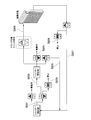


Classifications
-
- E—FIXED CONSTRUCTIONS
- E06—DOORS, WINDOWS, SHUTTERS, OR ROLLER BLINDS IN GENERAL; LADDERS
- E06B—FIXED OR MOVABLE CLOSURES FOR OPENINGS IN BUILDINGS, VEHICLES, FENCES OR LIKE ENCLOSURES IN GENERAL, e.g. DOORS, WINDOWS, BLINDS, GATES
- E06B9/00—Screening or protective devices for wall or similar openings, with or without operating or securing mechanisms; Closures of similar construction
- E06B9/02—Shutters, movable grilles, or other safety closing devices, e.g. against burglary
- E06B9/08—Roll-type closures
- E06B9/11—Roller shutters
- E06B9/15—Roller shutters with closing members formed of slats or the like
- E06B9/165—Roller shutters with closing members formed of slats or the like with slats disappearing in each other; with slats the distance between which can be altered
-
- E—FIXED CONSTRUCTIONS
- E06—DOORS, WINDOWS, SHUTTERS, OR ROLLER BLINDS IN GENERAL; LADDERS
- E06B—FIXED OR MOVABLE CLOSURES FOR OPENINGS IN BUILDINGS, VEHICLES, FENCES OR LIKE ENCLOSURES IN GENERAL, e.g. DOORS, WINDOWS, BLINDS, GATES
- E06B9/00—Screening or protective devices for wall or similar openings, with or without operating or securing mechanisms; Closures of similar construction
- E06B9/24—Screens or other constructions affording protection against light, especially against sunshine; Similar screens for privacy or appearance; Slat blinds
- E06B9/26—Lamellar or like blinds, e.g. venetian blinds
- E06B9/28—Lamellar or like blinds, e.g. venetian blinds with horizontal lamellae, e.g. non-liftable
- E06B9/34—Lamellar or like blinds, e.g. venetian blinds with horizontal lamellae, e.g. non-liftable roller-type; Roller shutters with adjustable lamellae
-
- E—FIXED CONSTRUCTIONS
- E06—DOORS, WINDOWS, SHUTTERS, OR ROLLER BLINDS IN GENERAL; LADDERS
- E06B—FIXED OR MOVABLE CLOSURES FOR OPENINGS IN BUILDINGS, VEHICLES, FENCES OR LIKE ENCLOSURES IN GENERAL, e.g. DOORS, WINDOWS, BLINDS, GATES
- E06B9/00—Screening or protective devices for wall or similar openings, with or without operating or securing mechanisms; Closures of similar construction
- E06B9/56—Operating, guiding or securing devices or arrangements for roll-type closures; Spring drums; Tape drums; Counterweighting arrangements therefor
- E06B9/68—Operating devices or mechanisms, e.g. with electric drive
-
- E—FIXED CONSTRUCTIONS
- E06—DOORS, WINDOWS, SHUTTERS, OR ROLLER BLINDS IN GENERAL; LADDERS
- E06B—FIXED OR MOVABLE CLOSURES FOR OPENINGS IN BUILDINGS, VEHICLES, FENCES OR LIKE ENCLOSURES IN GENERAL, e.g. DOORS, WINDOWS, BLINDS, GATES
- E06B9/00—Screening or protective devices for wall or similar openings, with or without operating or securing mechanisms; Closures of similar construction
- E06B9/02—Shutters, movable grilles, or other safety closing devices, e.g. against burglary
- E06B9/08—Roll-type closures
- E06B9/11—Roller shutters
- E06B9/15—Roller shutters with closing members formed of slats or the like
- E06B2009/1505—Slat details
- E06B2009/1527—Transparent slats or transparent sections in slats
-
- E—FIXED CONSTRUCTIONS
- E06—DOORS, WINDOWS, SHUTTERS, OR ROLLER BLINDS IN GENERAL; LADDERS
- E06B—FIXED OR MOVABLE CLOSURES FOR OPENINGS IN BUILDINGS, VEHICLES, FENCES OR LIKE ENCLOSURES IN GENERAL, e.g. DOORS, WINDOWS, BLINDS, GATES
- E06B9/00—Screening or protective devices for wall or similar openings, with or without operating or securing mechanisms; Closures of similar construction
- E06B9/02—Shutters, movable grilles, or other safety closing devices, e.g. against burglary
- E06B9/08—Roll-type closures
- E06B9/11—Roller shutters
- E06B9/15—Roller shutters with closing members formed of slats or the like
- E06B2009/1533—Slat connections
- E06B2009/155—Slats connected by separate elements
- E06B2009/1566—Rigid elements, e.g. hinges, hooks or profiles
-
- E—FIXED CONSTRUCTIONS
- E06—DOORS, WINDOWS, SHUTTERS, OR ROLLER BLINDS IN GENERAL; LADDERS
- E06B—FIXED OR MOVABLE CLOSURES FOR OPENINGS IN BUILDINGS, VEHICLES, FENCES OR LIKE ENCLOSURES IN GENERAL, e.g. DOORS, WINDOWS, BLINDS, GATES
- E06B9/00—Screening or protective devices for wall or similar openings, with or without operating or securing mechanisms; Closures of similar construction
- E06B9/56—Operating, guiding or securing devices or arrangements for roll-type closures; Spring drums; Tape drums; Counterweighting arrangements therefor
- E06B9/68—Operating devices or mechanisms, e.g. with electric drive
- E06B2009/6809—Control
-
- E—FIXED CONSTRUCTIONS
- E06—DOORS, WINDOWS, SHUTTERS, OR ROLLER BLINDS IN GENERAL; LADDERS
- E06B—FIXED OR MOVABLE CLOSURES FOR OPENINGS IN BUILDINGS, VEHICLES, FENCES OR LIKE ENCLOSURES IN GENERAL, e.g. DOORS, WINDOWS, BLINDS, GATES
- E06B9/00—Screening or protective devices for wall or similar openings, with or without operating or securing mechanisms; Closures of similar construction
- E06B9/56—Operating, guiding or securing devices or arrangements for roll-type closures; Spring drums; Tape drums; Counterweighting arrangements therefor
- E06B9/68—Operating devices or mechanisms, e.g. with electric drive
- E06B2009/6809—Control
- E06B2009/6818—Control using sensors
- E06B2009/6845—Control using sensors sensing position
-
- E—FIXED CONSTRUCTIONS
- E06—DOORS, WINDOWS, SHUTTERS, OR ROLLER BLINDS IN GENERAL; LADDERS
- E06B—FIXED OR MOVABLE CLOSURES FOR OPENINGS IN BUILDINGS, VEHICLES, FENCES OR LIKE ENCLOSURES IN GENERAL, e.g. DOORS, WINDOWS, BLINDS, GATES
- E06B9/00—Screening or protective devices for wall or similar openings, with or without operating or securing mechanisms; Closures of similar construction
- E06B9/56—Operating, guiding or securing devices or arrangements for roll-type closures; Spring drums; Tape drums; Counterweighting arrangements therefor
- E06B9/68—Operating devices or mechanisms, e.g. with electric drive
- E06B2009/6809—Control
- E06B2009/6872—Control using counters to determine shutter position
Definitions
- the present invention relates to a shutter device and a method for controlling the shutter device.
- a general shutter device has a shutter curtain formed by arranging a plurality of slats connected to each other in the vertical direction.
- a shutter device that can perform daylighting and ventilation in a room even when the shutter curtain is closed.
- the lower slat is pressed by the upper slat to open the movable wing provided in the lower slat, and the opening provided in the fixed wing is opened (ventilated state).
- this shutter device for example, by making the opening ventilated, it is possible to make it difficult to visually recognize the indoor state from the outdoor side by the movable wing, while allowing lighting and ventilation.
- the shutter curtain in the open state is closed and the movable wing is opened.
- the movable wings are closed without performing daylighting or ventilation, it is necessary to input an operation from the operation unit so that the shutter curtains are slightly wound up so that the slats do not press each other.
- the user inputs an instruction to wind up the shutter curtain so as to open the movable wing.
- the shutter curtain is rolled up more than necessary, and the skirting board is separated from the floor surface. May end up.
- the skirting board is separated from the floor surface, it is necessary to input an operation to close the shutter curtain, and depending on the operation input method, the shutter curtain is excessively lowered and the movable wing is opened. May end up.
- the present invention has been made in view of such circumstances, and provides a shutter device and a shutter device control method capable of easily controlling the movable feathers of the shutter curtain.
- a shutter device a fixed wing having an opening, a first position that is coupled to overlap the fixed wing, and closes the opening of the fixed wing, and the fixed wing.
- a movable wing that is movable to a second position that opens the opening, and a shutter curtain that closes the opening of the building; and the movable wing is in the first position, and the shutter curtain is moved to the building.
- the control part which has these.
- the control unit in the shutter device according to the first aspect, in the second mode, relatively moves the connected fixed wing and the movable wing to move the movable wing to the Separate from the fixed wings.
- the driving device further drives the shutter curtain in an opening direction or a closing direction, and the control unit drives the driving unit, From the second position where the movable wing and the fixed wing are separated by the second mode, the movable wing returns the movable wing to the first position where the opening of the fixed wing is closed. It further has a mode.
- the control unit can easily control the movable wing from the opened state to the closed state.
- the control device further includes an input unit that inputs an instruction to operate the shutter curtain. Based on the instruction of the first mode, after closing the building opening with the shutter curtain, the movable wing is moved to the second wing based on the instruction of the second mode from the input unit. Move to position.
- the control unit can perform control to open the movable wing based on an instruction from the input unit.
- the control unit further includes a detection unit that detects whether the shutter curtain is in the fully closed state. Based on the detection result of the detection unit, it is detected whether or not the shutter curtain is in the fully closed state. According to the shutter device of the fifth aspect, since the detection unit detects whether or not the shutter curtain is in the fully closed state, the control unit reliably grasps that the shutter curtain is in the fully closed state. In addition, the movable wings can be opened.
- the control unit determines that the mode can be changed.
- the control unit further includes a fourth mode in which the shutter curtain is fully opened.
- the control unit is set to any one of the first mode, the second mode, and the fourth mode based on an input of the input unit. Selectively move the shutter curtain.
- the control unit receives an instruction to shift from the input unit to the first mode, the second mode, or the fourth mode. After that, it accepts instructions for other modes.
- a fixed wing having an opening, a first position connected to the fixed wing so as to overlap with the fixed wing, and a second position for closing the opening of the fixed wing and the second opening of the fixed wing.
- a shutter curtain that closes a building opening, wherein the shutter is in a state in which the movable wing is in the first position.
- the shutter device is controlled according to the two modes.
- a fixed wing having an opening, a first position connected to the fixed wing so as to overlap with the fixed wing, and a second position for opening the opening of the fixed wing.
- a program for causing a computer to control the shutter device comprising a shutter curtain that closes a building opening, wherein the movable wing is in a first position.
- the computer is caused to execute the second mode of separating from the fixed wing.
- a twelfth aspect of the present invention is a shutter device, which is a fixed wing having an opening, a first position that is disposed so as to overlap the fixed wing, and closes the opening of the fixed wing, and the fixed wing.
- a movable wing that is movable to a second position that opens the opening, and includes a shutter curtain formed by connecting the fixed wing and the movable wing, and the connected fixed wing
- a control unit having a first mode in which the movable wing is located at a first position and a second mode in which the movable wing is located at the second position, based on relative movement between the movable wing and the movable wing.
- control unit can control the state where the movable wing is closed and the state where the movable wing is opened. Thereby, it is possible to easily control the closed state and the open state of the movable wing.
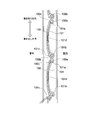
- FIG. 1 is a schematic view of a shutter device 1 according to an embodiment of the present invention. It is sectional drawing seen from the side skin
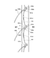
- FIG. 6 is a cross-sectional view of the slats connected to each other in a state where the movable wings are open, as viewed from the side skin side in the embodiment of the present invention.
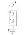
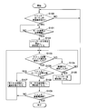
- It is a functional block diagram of the shutter apparatus 1 shown in FIG. 4 is a flowchart of the operation of the shutter curtain 20 in the embodiment of the present invention.
- FIG. 1 is a schematic view showing the appearance of a shutter device 1 according to an embodiment of the present invention.
- a shutter device 1 according to an embodiment of the present invention is configured by connecting a plurality of long slats 10 in the vertical direction, and a shutter curtain 20 capable of closing a building opening, A shutter box 30 and guide rails 40 and 50 are provided.
- the shutter box 30 is provided on the upper part of the shutter device 1 and includes a shaft 31 and a motor 32.
- the shaft 31 is connected to the upper end portion of the shutter curtain 20 and the motor 32.
- the shaft 31 is rotationally driven in the forward and reverse directions by the motor 32, and the slat 10 (shutter curtain 20) is unwound or taken up according to the rotation of the shaft 31.
- the motor 32 is a drive unit that drives the shaft 31, and is constituted by, for example, a DC motor.
- Both ends of the shutter curtain 20 in the width direction are guided by guide rails 40 and 50 erected from the floor surface to the ceiling portion, and lateral deviation of each slat 10 constituting the shutter curtain 20 is regulated by the guide rails 40 and 50. .
- the shaft 31 and the slat 10 wound around the shaft 31 are accommodated in the shutter box 30.
- FIGS. 2A and 2B are cross-sectional views of the plurality of slats 10 connected to each other as viewed from the side.
- the slat 10 has a movable wing 100 and a fixed wing 101.
- the movable wing 100 has a lower front hook 100a, an upper front hook 100b, and a middle front hook 100c formed at the upper end.
- the fixed wing 101 has an upper rear hook 101a at the upper end and a lower rear hook 101b and a protrusion 101c at the lower end.
- the fixed wing 101 has an opening 101d as shown in FIGS. 2A and 2B.
- the protrusion 101 c provided on the fixed wing 101 of the upper slat 10 and the upper front hook 100 b are engaged with the upper front hook 101 b provided on the movable wing 100 of the lower slat 10.
- the lower front hook 100 a and the middle front hook 100 c of the movable wing 100 of the lower slat 10 are engaged with the upper rear hook 101 a provided on the fixed wing 101 of the lower slat 10. Thereby, the some slat 10 is connected and the shutter curtain 20 is comprised.
- the slat provided with the movable wing 100 may be provided with at least one or more of the plurality of slats 10 constituting the shutter curtain 20.
- the opening 101d may be configured by opening a part of the width direction of the slat 10.
- a plurality of openings 101d may be provided for one slat 10.
- the opening 101d may be composed of a plurality of slit-shaped holes, or a wire mesh shape may be provided in the slit holes.
- a plurality of movable wings 100 may be provided in the width direction for each opening 101d of one slat 10 according to the opening 101d, or one movable wing 100 is provided for the plurality of openings 101d in the width direction. It may be provided.
- FIG. 2A is a cross-sectional view of the shutter curtain 20 in a state where the movable wing 100 is closed.
- a closed state a state in which the base plate of the shutter curtain 20 is in contact with the floor surface
- a pause state a state in which a part of the shutter curtain 20 is closed
- the state (closed state) in which at least a part is in contact with the fixed wing 101 so that the opening 101d is in the closed state and is positioned along the fixed wing 101 is shown.
- the opening 101d is in the closed state, so that light and wind from the outside cannot pass through the opening 101d to the indoor side.
- FIG. 2B is a cross-sectional view of the shutter curtain 20 in a state where the movable wing 100 is open.
- a closed state a state where the baseboard of the shutter curtain 20 is in contact with the floor surface
- the movable wing 100 is positioned so as to have an angle with respect to the fixed wing 101. This relative movement can be performed, for example, when the lower slat 10 is pressed by the upper slat 10.
- the opening 101d is in the open state, and light and wind from the outside can pass through the opening 101d to the indoor side.
- the motor 32 is rotated forward by a predetermined number of revolutions so as to further unwind the shutter curtain 20, whereby the tip portion x of the protrusion 101c of the upper slat 10 is moved.
- the movable wing 100 is opened with the upper end portion (upper rear hook 101a) of the fixed wing of the lower slat 10 as a fulcrum. It becomes a state.
- the motor 32 rotates reversely by a predetermined number of rotations so as to wind up the shutter curtain 20, so that the tip portion x of the protrusion 101c of the upper slat 10 is lowered.
- the movable wing 100 is in a closed state (FIG. 2A).
- FIG. 3 is a functional block diagram showing functions of the shutter device 1.
- the shutter device 1 includes an operation unit (input unit) 200, a control device 300, a detection unit 400, and a motor 32.
- the operation unit 200 is connected to the control device 300.
- the operation unit 200 is provided with an open switch 201, a stop switch 202, and a close switch 203.
- the user can perform normal operation or ventilation operation of the shutter curtain 20 by pressing these switches.
- the normal operation is an operation of closing the shutter curtain 20 and an operation of stopping the operation of the shutter curtain 20 during the opening / closing operation.
- the ventilation operation is an operation of opening the movable wing 100 of the slat 10 as described above.
- the operation unit 200 outputs a switch signal that is a signal corresponding to the switch to the control device 300.
- the communication between the operation unit 200 and the control device 300 may be wired or wireless.
- the detection unit 400 detects that the skirting board of the shutter curtain 20 is in contact with the floor surface.
- the detection unit 400 has a function of detecting, for example, the driving state (for example, load) of the motor 32.
- the detection unit 400 acquires position pulses from, for example, an encoder (not shown) built in the motor 32.
- the position pulse obtained from the encoder is output every time the motor 32 rotates by a predetermined amount. Further, the position pulse from the encoder increases in pulse width as the rotational speed of the motor 32 decreases, and decreases in pulse width as the rotational speed of the motor 32 increases. Therefore, the detection unit 400 calculates the rotational speed of the motor 32 as a load by counting the position pulses obtained from the encoder.
- the detection unit 400 may detect the rotation speed of the motor 32 as a load by obtaining the pulse width of the position pulse from the encoder.
- the detection unit 400 outputs the detection result to the control device 300.
- the control device 300 is connected to each of the operation unit 200, the motor 32, and the detection unit 400.
- the control device 300 includes, for example, a CPU (Central Processing Unit), a storage device, and the like, and controls driving of the motor 32 according to the operation of the switch of the operation unit 200.
- the control device 300 includes a control unit 301 and a driver 302.
- the control unit 301 has a first mode in which the shutter curtain 20 and the movable wing 100 are closed, a second mode in which the movable wing is opened based on relative movement from the state in which the shutter curtain is closed, There is a third mode in which the motor 32 is rotated in the reverse direction so that the movable wing opened in the second mode is closed again.
- control unit 301 can shift to the second mode when receiving an instruction to shift to the second mode from the operation unit 200 after the shutter curtain 20 is closed in the first mode. is there.
- the control unit 301 uses the driver 302 in response to a switch operation (hereinafter referred to as “switch operation”) of the operation unit 200 performed by the user in a state where the shutter curtain 20 has shifted from the open state to the closed state.
- the driving of the motor 32 is controlled. More specifically, the control unit 301 determines which switch of the operation unit 200 is pressed based on a switch signal obtained from the operation unit 200.
- the control unit 301 receives the switching signal from the operation unit 200, counted by the timer provided in itself, based on whether received continuously switch signal preset time above T 1 pressed It is determined whether or not the pressed switch is pressed and held. In addition, when the control unit 301 receives two or more different types of switch signals during a preset time T 2 ( ⁇ T 1 ) after timing, the user turns on the plurality of switches of the operation unit 200 together. It is determined that the button has been pressed.
- the control unit 301 determines that the user presses the open switch 201 of the operation unit 200 for a short time, the control unit 301 drives the motor 32 to wind the shutter curtain 20 around the shaft 31 and raises the command (hereinafter referred to as “open command”). .) To the driver 302. When the control unit 301 determines that the user has pressed the close switch 203 of the operation unit 200 for a short time, the control unit 301 drives the motor 32 to unwind the shutter curtain 20 from the shaft 31 and lowers the command (hereinafter referred to as a “close command”). .) To the driver 302.
- the control unit 301 When the user presses the stop switch 202 of the operation unit 200 for a short time, the control unit 301 outputs a command (stop command) to stop the operation of the shutter curtain 20 by stopping the driving of the motor 32 to the driver 302. . Note that, for example, the control unit 301 determines that the switch is pressed, if not received continuously switch signal preset time above T 1 is short pressed.
- the control unit 301 moves the movable wing 100 of the slat 10 to the motor 32.
- a command to operate (hereinafter referred to as “turn command”) is output to the driver 302.
- the slat selector switch operation is, for example, an operation of long-pressing any one predetermined switch of the operation unit 200 or an operation of pressing a plurality of different switches of the operation unit 200 together.
- the long pressing operation of the switch of the operation unit 200 may be any one of the open switch 201, the stop switch 202, and the close switch 203.
- the operation of pressing down a plurality of different switches of the operation unit 200 may be performed by pressing at least two of the open switch 201, the stop switch 202, and the close switch 203.
- a dedicated switch for shifting the shutter curtain 20 from the closed state to the ventilated state may be provided in the operation unit 200.
- the control unit 301 acquires the load from the detection unit 400 at regular intervals while performing the operation of closing the shutter curtain 20.
- the control unit 301 detects whether or not the shutter curtain is in a closed state by determining whether or not the acquired load is equal to or greater than a full-close threshold.
- the fully closed threshold value is a value for determining that the shutter curtain 20 is closed, and is a load value of the motor 32 when the baseboard of the shutter curtain 20 comes into contact with the floor surface.
- the fully closed threshold is determined according to the moving distance of the shutter curtain 20 from the open state to the closed state, for example.
- the position pulse obtained from the encoder becomes higher than the load of the motor during normal operation when the base plate of the shutter curtain 20 comes into contact with the floor surface, so that the pulse width increases and the rotation speed decreases.
- the control unit 301 determines that the baseboard of the shutter curtain 20 is in contact with the floor surface. In this case, the control unit 301 outputs a stop command to the driver 302, and the operation of the shutter curtain 20 is stopped.
- the control unit 301 determines that the shutter curtain 20 is not closed and continues outputting the close command to the driver 302.
- the control unit 301 determines the position of the shutter curtain 20 from the motor load and fluctuations of the load, that is, the opened state (fully opened state, fourth mode) where the shutter curtain 20 is wound up, and the closed state (fully closed state, 1 mode), a pause state, or a ventilation state (second mode).
- This temporary stop state can be determined by detecting whether or not the stop switch 202 is pressed before reaching the closed state or the open state during the closing operation or the opening operation.
- the control unit 301 specifies a preset number N and outputs a turning command to the motor 32 when the user performs a step changeover switch operation.
- the number N is the number of rotations of the motor 32 necessary to change the shutter curtain 20 from the closed state to the ventilated state, and is set in advance based on the results of experiments and the like.
- the control unit 301 specifies a preset number N and outputs a reverse turn command to the motor 32 when the user performs a step changeover switch operation.
- the reverse turning command is a command for causing the motor 32 to operate the movable wing 100 of the slat 10 in the reverse direction, that is, to make it close.
- the driver 302 controls the motor 32 by generating a drive signal for the motor 32 and outputting it to the motor 32 based on a command from the control unit 301.
- the driver 302 maintains a predetermined rotation speed regardless of the load variation during the opening operation or the closing operation of the shutter curtain 20.
- the driver 302 receives the turning command and rotates the motor 32 by the number N in the unwinding direction.
- the shutter curtain 20 enters a ventilation state.
- the driver 302 when the shutter curtain 20 is in a ventilated state, when the driver 302 receives a reverse turning command, the driver 302 rotates the motor 32 by the number N in the winding direction.
- the shutter curtain 20 is closed.
- step S ⁇ b> 100 the control unit 301 determines whether or not a closing operation switch signal is input from the operation unit 200 when the user presses the closing switch 203.
- step S100: NO the control unit 301 performs the determination in step S100 again.
- step S100: YES When the control unit 301 determines that the closing operation switch signal is input from the operation unit 200 (step S100: YES), the control unit 301 outputs a closing command to the driver 302.
- the driver 302 transmits the drive signal based on the close command to the motor 32 to drive the motor 32 in the unwinding direction. Thereby, since the shaft 31 connected to the motor 32 rotates in the unwinding direction, the slat 10 wound around the shaft 31 is unwound and the closing operation of the shutter device 1 is performed.
- step S101 the control unit 301 acquires the detection result of the motor load from the detection unit 400 at regular intervals during the closing operation of the shutter curtain 20, and determines whether or not the threshold value is equal to or greater than the full-closing threshold value.
- step S101: NO the control unit 301 continues the closing operation of the shutter curtain 20. If the motor load is equal to or greater than the fully closed threshold (step S101: YES), the process proceeds to step S102.
- the control unit 301 continues the closing operation of the shutter curtain 20 until the detection result of the motor load becomes equal to or greater than the fully closed threshold value.
- step S ⁇ b> 102 the control unit 301 outputs a stop command to the driver 302. Based on the stop command, the driver 302 stops the output of the drive signal to the motor 32 and stops the rotation of the motor 32. Thereby, the closing operation of the shutter curtain 20 is stopped.
- step S ⁇ b> 103 the control unit 301 determines whether a switch signal corresponding to the user's step changeover switch operation is detected from the operation unit 200. When the control unit 301 does not detect the user's step change switch operation (step S103: NO), the control unit 301 proceeds to step S104. On the other hand, the control part 301 progresses to step S106, when a user's step change switch operation is detected (step S103: YES).
- step S ⁇ b> 104 the control unit 301 determines whether the operation unit 200 has detected a switch signal corresponding to the opening operation from the operation unit 200. When the control unit 301 does not detect the opening operation switch signal from the operation unit 200 (step S104: NO), the control unit 301 returns to step S103. On the other hand, when the control unit 301 detects an opening operation (step S104: YES), the control unit 301 proceeds to step S105. In step S ⁇ b> 105, the control unit 301 outputs an open command to the driver 302. The driver 302 rotates the motor 32 in the winding direction by transmitting a drive signal based on the opening command to the motor 32. Here, the shutter device 1 continues the opening operation until the shutter curtain 20 is fully opened.
- step S106 the control unit 301 determines whether or not the shutter curtain 20 is in the closed state based on whether or not the load detection result of the motor 32 is equal to or greater than the fully closed threshold value.
- step S106: YES the control unit 301 proceeds to step S107.
- step S106: NO the control unit 301 proceeds to step S108.
- step S107 the control unit 301 designates a preset number of times N and outputs a turning command to the motor 32.
- the driver 302 transmits a drive signal based on the turning command to the motor 32, so that the motor 32 rotates N times in the unwinding direction. Therefore, the shaft 31 connected to the motor 32 rotates in the N rotation unwinding direction.
- the control unit 301 cannot close the shutter curtain 20 because the baseboard of the shutter curtain 20 is in contact with the floor surface. For this reason, in the shutter curtain 20, the lower slat 10 is pressed by the upper slat 10, the movable wing 100 is opened, and the ventilation is performed.
- the control unit 301 closes the shutter curtain 20, the process proceeds to step S103.
- step S ⁇ b> 108 the control unit 301 specifies a preset number N and outputs a reverse turn command to the motor 32 via the driver 302.
- the motor 32 rotates N times in the winding direction based on this signal. For this reason, in the shutter curtain 20, the lower slat 10 is not pressed by the upper slat 10, and the movable wing 100 is closed.
- step S109 the process proceeds to step S103 until the power supply to the shutter device 1 is stopped.
- the control device 300 ends the operation.
- step S201 when the user presses the open switch 201 when the shutter curtain 20 is in the open state, the shutter curtain 20 is already in the open state, and thus the closing operation is not performed.
- step S202 when the user presses the close switch 203, the shutter curtain 20 is closed and the closed state is entered (step S202).
- step S203 if the user presses the stop switch 202 during the closing operation of the shutter curtain 20, the control device 300 stops the closing operation of the shutter curtain 20. That is, the closed state is maintained halfway (step S203).
- step S204 When the shutter curtain 20 is in the closed state, when the user presses the close switch 203, the shutter curtain 20 is already in the closed state and does not operate (step S204).
- step S204 When the user presses the open switch 201, the shutter curtain 20 is opened to enter an open state (step S205).
- step S206 When the user operates the step changeover switch on the operation unit 200, the shutter curtain 20 enters the ventilation state (step S206).
- FIG. 6 is a diagram illustrating another example of the operation flow of the state transition of the switch of the operation unit 200 and the shutter curtain 20 according to the embodiment of the present invention. As shown in FIG. 6, when the shutter curtain 20 is in the ventilation state, when the user operates the step changeover switch on the switch of the operation unit 200, the shutter curtain 20 is closed.
- the shutter device 1 when the shutter curtain 20 is in the ventilation state, the shutter device 1 can shift the shutter curtain 20 to the closed state or the open state in accordance with the switch operation of the operation unit 200. Therefore, when the shutter curtain 20 is in a ventilated state, the shutter device 1 shifts the shutter curtain 20 to the closed state when the user performs an operation other than pressing the open switch 201 (for example, a step changeover switch operation). be able to.
- FIG. 7 is a diagram illustrating an operation flow of transition between the switch of the operation unit and the shutter curtain state (open state, closed state, pause state, ventilation state) in the conventional shutter device.
- the shutter curtain is closed to enter the ventilation state.
- the shutter curtain is in a ventilated state
- the shutter curtain is opened and the shutter curtain is opened.
- the conventional shutter device there is no mode in which the shutter curtain is closed. Therefore, when it is desired to close the shutter curtain, the user needs to manually press the stop switch with good timing while the shutter curtain is raised and lowered.
- the control device 300 has two modes of the first mode and the second mode, and changes the shutter curtain 20 from the open state to the closed state.
- the control device 300 can set the ventilation state in which the movable wing 100 of the slat 10 is operated based on the switch signal of the step changeover switch operation from the operation unit 200. Further, when the shutter curtain 20 is in a ventilated state, the control device 300 operates the movable wing 100 of the slat 10 in the reverse direction based on the switch signal of the step change switch operation supplied from the operation unit 200, and the shutter curtain 20. Can be closed. Thereby, when a user makes the shutter curtain 20 a closed state, operation does not become complicated. Also, the control device 300 can have further modes.
- the switch of the existing operation unit 200 is used as it is, and the switch operation of a pattern different from the normal operation of the shutter curtain 20 (for example, the operation of pressing both switches together) ), The shutter curtain 20 can be changed from the closed state to the ventilated state. Thus, it is not necessary to provide a new switch.
- the control device 300 determines whether or not the load calculated by the detection unit 400 from the encoder position pulse is equal to or greater than the full-close threshold.
- the present embodiment is not limited to this.
- a contact sensor or an optical sensor that detects contact with an object may be used. When the sensor is used, the sensor is disposed at either the lower end of the shutter curtain 20 or the lower end of the guide rails 40 and 50.
- the control device 300 stops the motor 32 by detecting this on / off state change.
- the control device 300 stores in advance in a storage unit (not shown) the number of times the motor 32 is rotated until the shutter curtain 20 changes from the open state to the closed state (hereinafter referred to as “total number of closes”). Keep it.
- the control device 300 reads the number of full closures stored in advance in the storage unit, and rotates the motor 32 until the number of rotations reaches the number of full closures. The number of full closures may be determined in advance by adjustment on site.
- the case where the instruction to open the movable feather 100 is input after the shutter curtain 20 is in the closed state has been described.
- the shutter curtain 20 is in the open state or the closing operation is performed.
- the control may be performed so that the movable wing 100 is continuously opened after the shutter curtain 20 is closed.
- the slat 10 is connected to the upper side and the lower side.
- the present invention is not limited to this configuration. For example, if it is the structure connected so that each slat 10 may adjoin, a connection direction is not limited to an up-down direction.
- control unit 301 controls the motor 32 by detecting a load change in the first mode, and opens and closes the shutter curtain 20. Further, the control unit 301 controls the motor 32 by detecting the rotation speed in the second mode, and opens and closes the movable wing 100.
- a shutter device having a drive unit that drives a shutter curtain including at least a part of a slat composed of a fixed wing and a movable wing that opens or closes an opening provided in the fixed wing in an opening direction or a closing direction.
- a control unit having a first mode for controlling the drive unit to open and close the shutter curtain and a second mode for controlling the drive unit to open and close the movable wing. Provided shutter device.
- Appendix 2 The shutter device according to appendix 1, wherein when the load of the driving unit is detected to change in the first mode, the number of rotations of the driving unit is detected in the second mode to open and close the movable wing.
- a shutter device having a drive unit that drives a shutter curtain including at least a part of a slat composed of a fixed wing and a movable wing that opens or closes an opening provided in the fixed wing in an opening direction or a closing direction.
- the control device 300 in the above-described embodiment may be realized by a computer.
- a program for realizing this function may be recorded on a computer-readable recording medium, and the program recorded on this recording medium may be read into a computer system and executed.
- the “computer system” includes an OS and hardware such as peripheral devices.
- the “computer-readable recording medium” refers to a storage device such as a flexible medium, a magneto-optical disk, a portable medium such as a ROM or a CD-ROM, and a hard disk incorporated in a computer system.
- the “computer-readable recording medium” dynamically holds a program for a short time like a communication line when transmitting a program via a network such as the Internet or a communication line such as a telephone line.
- a volatile memory inside a computer system serving as a server or a client in that case may be included and a program held for a certain period of time.
- the program may be a program for realizing a part of the above-described functions, and may be a program capable of realizing the functions described above in combination with a program already recorded in a computer system. It may be realized using a programmable logic device such as an FPGA (Field Programmable Gate Array).
Landscapes
- Engineering & Computer Science (AREA)
- Structural Engineering (AREA)
- Architecture (AREA)
- Civil Engineering (AREA)
- Operating, Guiding And Securing Of Roll- Type Closing Members (AREA)
Abstract
開口を有する固定羽と、固定羽に重なるように連結され、固定羽の開口を閉鎖する第1の位置と固定羽の開口を開放する第2の位置とに移動可能な可動羽と、を有し、建物開口部を閉鎖するシャッターカーテンと、可動羽が第1の位置にある状態で、シャッターカーテンを建物開口部を閉鎖する全閉状態とする第1のモードと、全閉状態から、可動羽が第2の位置にあるように可動羽を固定羽から離間させる第2のモードと、を有する制御部と、を備えるシャッター装置を提供する。
Description
本発明は、シャッター装置及びシャッター装置の制御方法に関する。
本願は、2013年10月31日に、日本に出願された特願2013-227682号に基づき優先権を主張し、その内容をここに援用する。
本願は、2013年10月31日に、日本に出願された特願2013-227682号に基づき優先権を主張し、その内容をここに援用する。
一般的なシャッター装置は、互いに連結されている複数のスラットが上下方向に配列して形成されるシャッターカーテンを有する。近年では、シャッターカーテンが閉まっている状態でも、室内への採光や通風ができるシャッター装置が要求されている。特許文献1には、上側のスラットによって下側のスラットを押し当てることで下側のスラットに設けられた可動羽を開け、固定羽に設けられた開口を開状態(通風状態)にする。このシャッター装置によれば、例えば、開口を通風状態とすることで、採光や通風を可能としながらも、可動羽により室外側から室内側の様子を視認しにくい状態とすることが可能となる。
上述したシャッター装置では、採光や通風をする目的から、シャッターカーテンを閉じるように操作装置から操作入力した場合には開状態のシャッターカーテンを閉状態にし、可動羽を開状態にするよう動作する。
しかしながら、採光や通風を行わず、可動羽を閉じるようにする場合には、各スラットが互いに押圧しないように、シャッターカーテンを少し巻き上げるように操作部から操作入力する必要がある。この場合、ユーザは、可動羽を開状態とするべく、シャッターカーテンを巻き上げる指示を操作入力するが、操作入力の仕方によっては、必要以上にシャッターカーテンを巻き上げてしまい、幅木が床面から離間してしまう場合がある。また、幅木が床面から離間した場合には、シャッターカーテンを閉じる操作入力をしなければならず、操作入力の仕方によっては、シャッターカーテンを巻き下げすぎてしまい、可動羽が開状態となってしまう場合がある。
しかしながら、採光や通風を行わず、可動羽を閉じるようにする場合には、各スラットが互いに押圧しないように、シャッターカーテンを少し巻き上げるように操作部から操作入力する必要がある。この場合、ユーザは、可動羽を開状態とするべく、シャッターカーテンを巻き上げる指示を操作入力するが、操作入力の仕方によっては、必要以上にシャッターカーテンを巻き上げてしまい、幅木が床面から離間してしまう場合がある。また、幅木が床面から離間した場合には、シャッターカーテンを閉じる操作入力をしなければならず、操作入力の仕方によっては、シャッターカーテンを巻き下げすぎてしまい、可動羽が開状態となってしまう場合がある。
本発明は、このような事情に鑑みてなされたもので、シャッターカーテンの可動羽を簡単に制御することができるシャッター装置及びシャッター装置の制御方法を提供する。
本発明の第1態様は、シャッター装置であって、開口を有する固定羽と、該固定羽に重なるように連結され、前記固定羽の前記開口を閉鎖する第1の位置と前記固定羽の前記開口を開放する第2の位置とに移動可能な可動羽と、を有し、建物開口部を閉鎖するシャッターカーテンと、前記可動羽が第1の位置にある状態で、前記シャッターカーテンを前記建物開口部を閉鎖する全閉状態とする第1のモードと、前記全閉状態から、前記可動羽が前記第2の位置にあるように前記可動羽を前記固定羽から離間させる第2のモードと、を有する制御部と、を備える。
本発明の第2態様は、上記第1態様のシャッター装置において、前記第2のモードにおいて、前記制御部が、連結された前記固定羽と前記可動羽とを相対移動させ、前記可動羽を前記固定羽から離間させる。
本発明の第3態様は、上記第1又は第2態様のシャッター装置において、前記シャッターカーテンを開方向または閉方向に駆動させる駆動部をさらに備え、前記制御部は、前記駆動部を駆動させ、前記第2のモードによって前記可動羽と前記固定羽とが離間された第2の位置から、前記可動羽が前記固定羽の前記開口を閉鎖する第1の位置に前記可動羽を戻す第3のモードをさらに有する。
上記第3態様のシャッター装置によれば、制御部は、可動羽を開けた状態から閉じた状態へ簡単に制御することができる。
本発明の第3態様は、上記第1又は第2態様のシャッター装置において、前記シャッターカーテンを開方向または閉方向に駆動させる駆動部をさらに備え、前記制御部は、前記駆動部を駆動させ、前記第2のモードによって前記可動羽と前記固定羽とが離間された第2の位置から、前記可動羽が前記固定羽の前記開口を閉鎖する第1の位置に前記可動羽を戻す第3のモードをさらに有する。
上記第3態様のシャッター装置によれば、制御部は、可動羽を開けた状態から閉じた状態へ簡単に制御することができる。
本発明の第4態様は、上記第1から第3態様のいずれかのシャッター装置において、前記シャッターカーテンを操作する指示を入力する入力部をさらに備え、前記制御部は、前記入力部から前記第1のモードが指示されたことに基づいて、前記シャッターカーテンで建物開口部を閉じた後に、前記入力部から前記第2のモードが指示されたことに基づいて、前記可動羽を前記第2の位置に移動させる。
上記第4態様のシャッター装置によれば、制御部は、入力部からの指示に基づいて、可動羽を開けるように制御することができる。これにより、ユーザは、入力部に指示を入力することで、可動羽を簡単に開閉することができる。
上記第4態様のシャッター装置によれば、制御部は、入力部からの指示に基づいて、可動羽を開けるように制御することができる。これにより、ユーザは、入力部に指示を入力することで、可動羽を簡単に開閉することができる。
本発明の第5態様は、上記第1から第4態様のいずれかのシャッター装置において、前記シャッターカーテンが前記全閉状態であるか否かを検出する検出部をさらに備え、前記制御部は、前記検出部の検出結果に基づいて、前記シャッターカーテンが前記全閉状態であるか否かを検出する。
上記第5態様のシャッター装置によれば、シャッターカーテンが全閉状態であるか否かを検出部が検出するようにしたので、制御部は、シャッターカーテンが全閉状態であることを確実に把握した上で、可動羽を開けることが可能となる。
本発明の第6態様は、上記第5態様のいずれかのシャッター装置において、前記制御部が、前記検出部の検出結果に基づいて、前記シャッターカーテンが前記全閉状態であれば、前記第2モードに移行可と判断する。
本発明の第7態様は、上記第1から第4態様のいずれかのシャッター装置において、前記制御部は、前記シャッターカーテンが巻き上げられた全開状態とする第4のモードをさらに備える。
本発明の第8態様は、上記第7態様のシャッター装置において、前記制御部は、前記入力部の入力に基づいて、前記第1モード、第2モード、又は第4モードのいずれかに、前記シャッターカーテンを選択的に移行させる。
本発明の第9態様は、上記第8態様のシャッター装置において、前記制御部は、前記入力部から前記第1モード、第2モード、又は第4モードのいずれかのモードへの移行指示を受け付けた後に、他のモードへの指示を受け付ける。
上記第5態様のシャッター装置によれば、シャッターカーテンが全閉状態であるか否かを検出部が検出するようにしたので、制御部は、シャッターカーテンが全閉状態であることを確実に把握した上で、可動羽を開けることが可能となる。
本発明の第6態様は、上記第5態様のいずれかのシャッター装置において、前記制御部が、前記検出部の検出結果に基づいて、前記シャッターカーテンが前記全閉状態であれば、前記第2モードに移行可と判断する。
本発明の第7態様は、上記第1から第4態様のいずれかのシャッター装置において、前記制御部は、前記シャッターカーテンが巻き上げられた全開状態とする第4のモードをさらに備える。
本発明の第8態様は、上記第7態様のシャッター装置において、前記制御部は、前記入力部の入力に基づいて、前記第1モード、第2モード、又は第4モードのいずれかに、前記シャッターカーテンを選択的に移行させる。
本発明の第9態様は、上記第8態様のシャッター装置において、前記制御部は、前記入力部から前記第1モード、第2モード、又は第4モードのいずれかのモードへの移行指示を受け付けた後に、他のモードへの指示を受け付ける。
本発明の第10態様は、開口を有する固定羽と、該固定羽に重なるように連結され、前記固定羽の前記開口を閉鎖する第1の位置と前記固定羽の前記開口を開放する第2の位置とに移動可能な可動羽と、を有し、建物開口部を閉鎖するシャッターカーテンを備える、シャッター装置の制御方法であって、前記可動羽が第1の位置にある状態で、前記シャッターカーテンを前記建物開口部を閉鎖する全閉状態とする第1のモードと、前記全閉状態から、前記可動羽が前記第2の位置にあるように前記可動羽を前記固定羽から離間させる第2のモードと、に従って前記シャッター装置を制御する。
本発明の第11態様は、開口を有する固定羽と、該固定羽に重なるように連結され、前記固定羽の前記開口を閉鎖する第1の位置と前記固定羽の前記開口を開放する第2の位置とに移動可能な可動羽と、を有し、建物開口部を閉鎖するシャッターカーテンを備える、シャッター装置の制御をコンピュータに実行させるためのプログラムであって、前記可動羽が第1の位置にある状態で、前記シャッターカーテンを前記建物開口部を閉鎖する全閉状態とする第1のモードと、前記全閉状態から、前記可動羽が前記第2の位置にあるように前記可動羽を前記固定羽から離間させる第2のモードと、をコンピュータに実行させる。
本発明の第12態様は、シャッター装置であって、開口を有する固定羽と、該固定羽に重なるように配置され、前記固定羽の前記開口を閉鎖する第1の位置と前記固定羽の前記開口を開放する第2の位置とに移動可能な可動羽と、を有し、前記固定羽と前記可動羽とが連結されて形成されるシャッターカーテンと、を備え、前記連結された前記固定羽と前記可動羽との相対移動に基づいて、前記可動羽が第1の位置に位置する第1モードと、前記可動羽が前記第2の位置に位置する第2モードと、を有する制御部と、を備える。
本発明の第11態様は、開口を有する固定羽と、該固定羽に重なるように連結され、前記固定羽の前記開口を閉鎖する第1の位置と前記固定羽の前記開口を開放する第2の位置とに移動可能な可動羽と、を有し、建物開口部を閉鎖するシャッターカーテンを備える、シャッター装置の制御をコンピュータに実行させるためのプログラムであって、前記可動羽が第1の位置にある状態で、前記シャッターカーテンを前記建物開口部を閉鎖する全閉状態とする第1のモードと、前記全閉状態から、前記可動羽が前記第2の位置にあるように前記可動羽を前記固定羽から離間させる第2のモードと、をコンピュータに実行させる。
本発明の第12態様は、シャッター装置であって、開口を有する固定羽と、該固定羽に重なるように配置され、前記固定羽の前記開口を閉鎖する第1の位置と前記固定羽の前記開口を開放する第2の位置とに移動可能な可動羽と、を有し、前記固定羽と前記可動羽とが連結されて形成されるシャッターカーテンと、を備え、前記連結された前記固定羽と前記可動羽との相対移動に基づいて、前記可動羽が第1の位置に位置する第1モードと、前記可動羽が前記第2の位置に位置する第2モードと、を有する制御部と、を備える。
上記本発明に係る態様によれば、制御部が、可動羽を閉じた状態と可動羽を開いた状態とを制御することが可能となる。これにより、可動羽の閉状態と開状態を簡単に制御することが可能となる。
以下、本発明のー実施形態におけるシャッター装置1を、図面を用いて説明する。図1は、本発明のー実施形態におけるシャッター装置1の外観を表す概略図である。
図1に示すように、本発明のー実施形態におけるシャッター装置1は、長尺な複数のスラット10が上下方向に連結されることで構成され、建物開口部を閉鎖可能なシャッターカーテン20と、シャッターボックス30と、ガイドレール40、50を有している。
図1に示すように、本発明のー実施形態におけるシャッター装置1は、長尺な複数のスラット10が上下方向に連結されることで構成され、建物開口部を閉鎖可能なシャッターカーテン20と、シャッターボックス30と、ガイドレール40、50を有している。
シャッターボックス30は、シャッター装置1の上部に設けられており、シャフト31とモータ32とを有している。シャフト31は、シャッターカーテン20の上端部とモータ32とに連結されている。シャフト31は、モータ32によって正逆方向に回転駆動され、シャフト31の回転に応じて、スラット10(シャッターカーテン20)の巻き出し、又は、巻き取りが行われる。モータ32は、シャフト31を駆動する駆動部であり、例えば直流モータから構成されている。
シャッターカーテン20の幅方向の両端は、床面から天井部分にかけて立設されるガイドレール40、50によってガイドされ、シャッターカーテン20を構成する各スラット10の横ずれがガイドレール40、50によって規制される。シャフト31及びシャフト31に巻き取られたスラット10は、シャッターボックス30内に収容されるようになっている。
次に、シャッターカーテン20の構造について、図2A、図2Bを用いて説明する。図2A、図2Bは、互いに連結された複数のスラット10の側面側から見た断面図である。
スラット10は、可動羽100と固定羽101を有している。可動羽100は、上端部に下前フック100aと上前フック100bと中前フック100cとが形成されている。
固定羽101は、上端部に上後フック101aと下端部に下後フック101bと突起部101cとが形成されている。また、固定羽101は、図2A、図2Bに示すように、開口101dが形成されている。次に上側と下側に連結されるスラット10について説明する。上側のスラット10の固定羽101に設けられた突起部101cと上前フック100bとが、下側のスラット10の可動羽100に設けられた上前フック101bに対して係合される。下側のスラット10の可動羽100の下前フック100aと中前フック100cとが、下側スラット10の固定羽101に設けられた上後フック101aに対して係合される。これにより、複数のスラット10どうしが連結され、シャッターカーテン20が構成されている。
ここでは、可動羽100が設けられたスラットは、シャッターカーテン20を構成する複数のスラット10のうち、少なくとも一つ以上設けられていればよい。また、開口101dは、スラット10の幅方向のうち、一部が開口されることによって構成されてもよい。また、開口101dは、1つのスラット10に対し複数設けられてもよい。この開口101dは、複数のスリット状の孔から構成されてもよいし、スリット孔に金網状が設けられてもよい。この場合、可動羽100は、開口101dに応じて1つのスラット10の開口101d毎に幅方向に複数設けられてもよいし、幅方向にある複数の開口101dに対して1つの可動羽100が設けられるようにしてもよい。
スラット10は、可動羽100と固定羽101を有している。可動羽100は、上端部に下前フック100aと上前フック100bと中前フック100cとが形成されている。
固定羽101は、上端部に上後フック101aと下端部に下後フック101bと突起部101cとが形成されている。また、固定羽101は、図2A、図2Bに示すように、開口101dが形成されている。次に上側と下側に連結されるスラット10について説明する。上側のスラット10の固定羽101に設けられた突起部101cと上前フック100bとが、下側のスラット10の可動羽100に設けられた上前フック101bに対して係合される。下側のスラット10の可動羽100の下前フック100aと中前フック100cとが、下側スラット10の固定羽101に設けられた上後フック101aに対して係合される。これにより、複数のスラット10どうしが連結され、シャッターカーテン20が構成されている。
ここでは、可動羽100が設けられたスラットは、シャッターカーテン20を構成する複数のスラット10のうち、少なくとも一つ以上設けられていればよい。また、開口101dは、スラット10の幅方向のうち、一部が開口されることによって構成されてもよい。また、開口101dは、1つのスラット10に対し複数設けられてもよい。この開口101dは、複数のスリット状の孔から構成されてもよいし、スリット孔に金網状が設けられてもよい。この場合、可動羽100は、開口101dに応じて1つのスラット10の開口101d毎に幅方向に複数設けられてもよいし、幅方向にある複数の開口101dに対して1つの可動羽100が設けられるようにしてもよい。
図2Aは、可動羽100が閉じている状態におけるシャッターカーテン20の断面図である。この図において、シャッターカーテン20が閉状態(シャッターカーテン20の幅木が床面に当接している状態)あるいは、シャッターカーテン20の一部を閉じた状態(一時停止状態)において、可動羽100は、開口101dが閉状態となるように固定羽101に対して少なくとも一部分が当接し、かつ固定羽101に沿うように位置している状態(閉状態)を表している。可動羽100が閉状態である場合、開口101dが閉状態となるため、室外からの光や風は、開口101dから室内側に通過することができない。
図2Bは、可動羽100が開いている状態におけるシャッターカーテン20の断面図である。この図において、シャッターカーテン20が閉状態(シャッターカーテン20の幅木が床面に当接している状態)である場合において、上側のスラット10と下側のスラット10との相対移動に基づいて、可動羽100が開状態となる状態を表している。可動羽100は、固定羽101に対して角度を有するように位置している。
この相対移動は、例えば、上側のスラット10によって下側のスラット10が押圧されることで、行うことができる。
可動羽100が開状態である場合、開口101dが開状態となり、室外からの光や風が、開口101dから室内側に通過することが可能となる。
ここでは、シャッターカーテン20が閉状態となった後、さらにシャッターカーテン20を巻き出すようにモータ32が所定の回転数だけ正回転することによって、上側のスラット10の突起部101cの先端部xが、下側のスラット10の可動羽100の当接面yの室内側を押圧することにより、下側のスラット10の固定羽の上端部(上後フック101a)を支点とし、可動羽100が開状態となる。また、可動羽100が開状態となった後、シャッターカーテン20を巻き取るようにモータ32が所定の回転数だけ逆回転することによって、上側のスラット10の突起部101cの先端部xが、下側のスラット10の可動羽100の当接面yから離間することで、可動羽100が閉状態(図2A)となる。
この相対移動は、例えば、上側のスラット10によって下側のスラット10が押圧されることで、行うことができる。
可動羽100が開状態である場合、開口101dが開状態となり、室外からの光や風が、開口101dから室内側に通過することが可能となる。
ここでは、シャッターカーテン20が閉状態となった後、さらにシャッターカーテン20を巻き出すようにモータ32が所定の回転数だけ正回転することによって、上側のスラット10の突起部101cの先端部xが、下側のスラット10の可動羽100の当接面yの室内側を押圧することにより、下側のスラット10の固定羽の上端部(上後フック101a)を支点とし、可動羽100が開状態となる。また、可動羽100が開状態となった後、シャッターカーテン20を巻き取るようにモータ32が所定の回転数だけ逆回転することによって、上側のスラット10の突起部101cの先端部xが、下側のスラット10の可動羽100の当接面yから離間することで、可動羽100が閉状態(図2A)となる。
図3は、シャッター装置1の機能を表す機能ブロック図である。この図において、シャッター装置1は、操作部(入力部)200と、制御装置300と、検出部400と、モータ32を備えている。
操作部200は、制御装置300に接続されている。操作部200は、開スイッチ201、停止スイッチ202、閉スイッチ203が設けられている。ユーザは、これらのスイッチを押下することで、シャッターカーテン20の通常操作又は通風操作を行うことができる。通常動作は、シャッターカーテン20を閉める操作と開閉動作中のシャッターカーテン20の動作を停止させる操作である。通風操作は、上述したようにスラット10の可動羽100を開く操作である。操作部200は、ユーザによっていずれかのスイッチが押下されると、制御装置300にスイッチに応じた信号であるスイッチ信号を出力する。この操作部200と制御装置300との通信は、有線でもよいし、無線によって行ってもよい。
操作部200は、制御装置300に接続されている。操作部200は、開スイッチ201、停止スイッチ202、閉スイッチ203が設けられている。ユーザは、これらのスイッチを押下することで、シャッターカーテン20の通常操作又は通風操作を行うことができる。通常動作は、シャッターカーテン20を閉める操作と開閉動作中のシャッターカーテン20の動作を停止させる操作である。通風操作は、上述したようにスラット10の可動羽100を開く操作である。操作部200は、ユーザによっていずれかのスイッチが押下されると、制御装置300にスイッチに応じた信号であるスイッチ信号を出力する。この操作部200と制御装置300との通信は、有線でもよいし、無線によって行ってもよい。
検出部400は、シャッターカーテン20の幅木が床面に当接したことを検知する。検出部400は、例えば、モータ32の駆動状況(例えば負荷)を検出する機能を有する。
検出部400は、例えばモータ32に内蔵されたエンコーダ(不図示)から位置パルスを取得する。エンコーダから得られる位置パルスは、モータ32が所定量回転する毎に出力される。また、エンコーダからの位置パルスは、モータ32の回転速度が遅くなるに従ってそのパルス幅が大きくなり、モータ32の回転速度が速くなるに従ってそのパルス幅が小さくなる。よって、検出部400は、エンコーダから得られる位置パルスをカウントすることによりモータ32の回転数を負荷として算出する。また、検出部400は、エンコーダからの位置パルスのパルス幅を求めることによりモータ32の回転速度を負荷として検出しても良い。検出部400は、検出結果を制御装置300に出力する。
検出部400は、例えばモータ32に内蔵されたエンコーダ(不図示)から位置パルスを取得する。エンコーダから得られる位置パルスは、モータ32が所定量回転する毎に出力される。また、エンコーダからの位置パルスは、モータ32の回転速度が遅くなるに従ってそのパルス幅が大きくなり、モータ32の回転速度が速くなるに従ってそのパルス幅が小さくなる。よって、検出部400は、エンコーダから得られる位置パルスをカウントすることによりモータ32の回転数を負荷として算出する。また、検出部400は、エンコーダからの位置パルスのパルス幅を求めることによりモータ32の回転速度を負荷として検出しても良い。検出部400は、検出結果を制御装置300に出力する。
制御装置300は、操作部200とモータ32と検出部400との各々に接続されている。制御装置300は、例えばCPU(Central Processing Unit)や記憶装置などから構成され、操作部200のスイッチの操作に応じてモータ32の駆動を制御する。
制御装置300は、制御部301と、ドライバ302とを備えている。
制御部301は、シャッターカーテン20と可動羽100とを閉じた状態である第1のモードと、シャッターカーテンを閉じた状態から相対移動に基づいて可動羽を開状態にする第2のモードと、第2のモードによって開状態となった可動羽を再び閉状態とするためモータ32を逆回転させる第3のモードを有する。
また、制御部301は、第1のモードによってシャッターカーテン20が閉状態となった後に、操作部200から第2のモードに移行する指示の入力を受けた場合に第2のモードに移行可能である。例えば、制御部301は、シャッターカーテン20が開状態から閉状態に移行した状態において、ユーザが行った操作部200のスイッチの操作(以下、「スイッチ操作」という。)に応じて、ドライバ302によって、モータ32の駆動を制御する。より具体的に、制御部301は、操作部200から得られるスイッチ信号に基づいて操作部200のどのスイッチが押されたかを判定する。また、制御部301は、操作部200からスイッチ信号を受信すると、自身に設けられたタイマーによって計時し、スイッチ信号を予め設定された時間T1以上継続して受信したか否かに基づいて押下されたスイッチが長押しされているか否かを判定する。
また、制御部301は、計時してから予め設定された時間T2(≦T1)の間に、異なる2種類以上のスイッチ信号を受信した場合、ユーザが操作部200の複数のスイッチを共に押下したと判定する。
制御装置300は、制御部301と、ドライバ302とを備えている。
制御部301は、シャッターカーテン20と可動羽100とを閉じた状態である第1のモードと、シャッターカーテンを閉じた状態から相対移動に基づいて可動羽を開状態にする第2のモードと、第2のモードによって開状態となった可動羽を再び閉状態とするためモータ32を逆回転させる第3のモードを有する。
また、制御部301は、第1のモードによってシャッターカーテン20が閉状態となった後に、操作部200から第2のモードに移行する指示の入力を受けた場合に第2のモードに移行可能である。例えば、制御部301は、シャッターカーテン20が開状態から閉状態に移行した状態において、ユーザが行った操作部200のスイッチの操作(以下、「スイッチ操作」という。)に応じて、ドライバ302によって、モータ32の駆動を制御する。より具体的に、制御部301は、操作部200から得られるスイッチ信号に基づいて操作部200のどのスイッチが押されたかを判定する。また、制御部301は、操作部200からスイッチ信号を受信すると、自身に設けられたタイマーによって計時し、スイッチ信号を予め設定された時間T1以上継続して受信したか否かに基づいて押下されたスイッチが長押しされているか否かを判定する。
また、制御部301は、計時してから予め設定された時間T2(≦T1)の間に、異なる2種類以上のスイッチ信号を受信した場合、ユーザが操作部200の複数のスイッチを共に押下したと判定する。
制御部301は、ユーザが操作部200の開スイッチ201が短押しされたと判定した場合、モータ32の駆動によりシャッターカーテン20をシャフト31に巻き取らせて上昇させる指令(以下、「開指令」という。)をドライバ302に対して出力する。制御部301は、ユーザが操作部200の閉スイッチ203を短押しされたと判定した場合、モータ32の駆動によりシャッターカーテン20をシャフト31から巻き出させて下降させる指令(以下、「閉指令」という。)をドライバ302に対して出力する。制御部301は、ユーザが操作部200の停止スイッチ202を短押しした場合、モータ32の駆動を停止することでシャッターカーテン20の動作を停止させる指令(停止指令)をドライバ302に対して出力する。なお、例えば、制御部301は、スイッチ信号を予め設定された時間T1以上継続して受信していない場合に押下されたスイッチが短押しされていると判定する。
また、制御部301は、上述した通常操作をさせるスイッチ操作とは別のスイッチ操作(以下、「スラット切替スイッチ操作」という。)をユーザが行った場合、モータ32にスラット10の可動羽100を稼動させる指令(以下、「旋回指令」という。)をドライバ302に対して出力する。スラット切替スイッチ操作は、例えば操作部200のうち予め決められたいずれか1つのスイッチを長押しする操作や操作部200の複数の異なるスイッチを共に押下する操作である。操作部200のスイッチの長押し操作は、開スイッチ201、停止スイッチ202、閉スイッチ203のいずれかのスイッチであってもよい。
また、操作部200の複数の異なるスイッチを共に押下する操作は、開スイッチ201、停止スイッチ202、閉スイッチ203のうち少なくとも2以上のスイッチを押下すればよい。なお、シャッターカーテン20が閉状態から通風状態に移行する専用のスイッチを操作部200に設けても良い。
また、操作部200の複数の異なるスイッチを共に押下する操作は、開スイッチ201、停止スイッチ202、閉スイッチ203のうち少なくとも2以上のスイッチを押下すればよい。なお、シャッターカーテン20が閉状態から通風状態に移行する専用のスイッチを操作部200に設けても良い。
制御部301は、シャッターカーテン20を閉じる動作を行っている間、検出部400から負荷を一定周期毎に取得する。制御部301は、取得した負荷が全閉閾値以上か否かを判定することで、シャッターカーテンが閉状態であるか否かを検出する。全閉閾値は、シャッターカーテン20が閉じられたことを判定する値であり、シャッターカーテン20の幅木が床面に当接したときのモータ32の負荷の値である。この全閉閾値は、例えば開状態から閉状態になるまでのシャッターカーテン20の移動距離に応じて決められている。なお、エンコーダから得られる位置パルスは、シャッターカーテン20の幅木が床面に当接すると通常動作時のモータの負荷よりも高くなるため、パルス幅が大きくなり、回転数が低下する。
制御部301は、検出部400から取得した負荷が全閉閾値以上の場合、シャッターカーテン20の幅木が床面に当接したと判定する。この場合、制御部301はドライバ302に停止指令を出力し、シャッターカーテン20の動作が停止する。一方、制御部301は、検出部400から取得した負荷が全閉閾値未満の場合、シャッターカーテン20が閉じられていないと判定し、ドライバ302に対する閉指令の出力を継続する。なお、制御部301は、モータの負荷及びその負荷の変動からシャッターカーテン20の位置、つまりシャッターカーテン20が巻き上げられた開状態(全開状態、第4のモード)、閉状態(全閉状態、第1のモード)、一時停止状態、通風状態(第2のモード)のいずれかであるか判定することができる。この一時停止状態は、閉動作あるいは開動作を行っている途中において、閉状態あるいは開状態に到達する前に停止スイッチ202が押下されたか否かを検出することによって判定可能である。
制御部301は、検出部400から取得した負荷が全閉閾値以上の場合、シャッターカーテン20の幅木が床面に当接したと判定する。この場合、制御部301はドライバ302に停止指令を出力し、シャッターカーテン20の動作が停止する。一方、制御部301は、検出部400から取得した負荷が全閉閾値未満の場合、シャッターカーテン20が閉じられていないと判定し、ドライバ302に対する閉指令の出力を継続する。なお、制御部301は、モータの負荷及びその負荷の変動からシャッターカーテン20の位置、つまりシャッターカーテン20が巻き上げられた開状態(全開状態、第4のモード)、閉状態(全閉状態、第1のモード)、一時停止状態、通風状態(第2のモード)のいずれかであるか判定することができる。この一時停止状態は、閉動作あるいは開動作を行っている途中において、閉状態あるいは開状態に到達する前に停止スイッチ202が押下されたか否かを検出することによって判定可能である。
制御部301は、シャッターカーテン20が閉状態である場合、ユーザによってステップ切替スイッチ操作が行われると、予め設定された回数Nを指定するとともに旋回指令をモータ32に出力する。回数Nは、シャッターカーテン20を閉状態から通風状態にするのに必要なモータ32を回転させる回数であり、実験等を行った結果に基づいて予め設定されている。
また、制御部301は、シャッターカーテン20が通風状態である場合、ユーザによってステップ切替スイッチ操作が行われると、予め設定された回数Nを指定するとともに逆旋回指令をモータ32に出力する。逆旋回指令は、モータ32にスラット10の可動羽100を逆方向に稼動させる、つまり閉状態にする指令である。
また、制御部301は、シャッターカーテン20が通風状態である場合、ユーザによってステップ切替スイッチ操作が行われると、予め設定された回数Nを指定するとともに逆旋回指令をモータ32に出力する。逆旋回指令は、モータ32にスラット10の可動羽100を逆方向に稼動させる、つまり閉状態にする指令である。
ドライバ302は、制御部301からの指令に基づいて、モータ32の駆動信号を生成しモータ32に出力することでモータ32の制御を行っている。ドライバ302は、シャッターカーテン20の開動作又は閉動作中において負荷変動にかかわらず所定の回転速度を維持させている。シャッターカーテン20が閉状態の場合、ドライバ302は、旋回指令を受信すると、モータ32を巻き出し方向に回数Nだけ回転させる。これより、シャッターカーテン20は通風状態になる。一方、シャッターカーテン20が通風状態の場合、ドライバ302は逆旋回指令を受信すると、モータ32を巻き取り方向に回数Nだけ回転させる。これより、シャッターカーテン20は閉状態になる。
次に、シャッター装置の制御装置300の動作について、図4のフローチャートに基づいて説明する。図4は、本実施形態におけるシャッターカーテン20の動作のフローチャートである。ここでは、シャッターカーテン20の初期状態として、シャッターカーテン20が開状態である場合を説明する。
ステップS100において、制御部301は、ユーザが閉スイッチ203を押下することで操作部200から閉操作のスイッチ信号が入力されたか否かの判定を行う。制御部301は、操作部200から閉操作のスイッチ信号が入力されていないと判定した場合(ステップS100:NO)、制御部301は、再度ステップS100の判定を行う。制御部301は、操作部200から閉操作のスイッチ信号が入力されたと判定した場合(ステップS100:YES)、制御部301は、閉指令をドライバ302に出力する。ドライバ302は、モータ32に対し閉指令に基づいた駆動信号を送信することで、モータ32を巻き出し方向に駆動させる。これにより、モータ32に連結されたシャフト31が巻き出し方向に回転するため、シャフト31に巻かれたスラット10が巻き出され、シャッター装置1の閉動作が行われる。
ステップS100において、制御部301は、ユーザが閉スイッチ203を押下することで操作部200から閉操作のスイッチ信号が入力されたか否かの判定を行う。制御部301は、操作部200から閉操作のスイッチ信号が入力されていないと判定した場合(ステップS100:NO)、制御部301は、再度ステップS100の判定を行う。制御部301は、操作部200から閉操作のスイッチ信号が入力されたと判定した場合(ステップS100:YES)、制御部301は、閉指令をドライバ302に出力する。ドライバ302は、モータ32に対し閉指令に基づいた駆動信号を送信することで、モータ32を巻き出し方向に駆動させる。これにより、モータ32に連結されたシャフト31が巻き出し方向に回転するため、シャフト31に巻かれたスラット10が巻き出され、シャッター装置1の閉動作が行われる。
ステップS101において、制御部301は、シャッターカーテン20の閉動作中に、検出部400から一定時間毎にモータの負荷の検出結果を取得し、全閉閾値以上か否か判定する。モータの負荷が全閉閾値未満の場合(ステップS101:NO)、制御部301は、シャッターカーテン20の閉動作を継続する。モータの負荷が全閉閾値以上の場合(ステップS101:YES)、ステップS102に進む。なお、制御部301は、モータの負荷の検出結果が全閉閾値以上になるまでシャッターカーテン20の閉動作を継続する。
ステップS102において、制御部301は、停止指令をドライバ302に出力する。
ドライバ302は、停止指令に基づき、モータ32に駆動信号の出力を停止し、モータ32の回転を停止させる。これにより、シャッターカーテン20の閉動作が停止する。
ステップS103において、制御部301は、操作部200からユーザのステップ切替スイッチ操作に応じたスイッチ信号を検知したか否かを判定する。制御部301は、ユーザのステップ切替スイッチ操作を検知しない場合(ステップS103:NO)、ステップS104に進む。一方、制御部301は、ユーザのステップ切替スイッチ操作を検知した場合(ステップS103:YES)、ステップS106に進む。
ドライバ302は、停止指令に基づき、モータ32に駆動信号の出力を停止し、モータ32の回転を停止させる。これにより、シャッターカーテン20の閉動作が停止する。
ステップS103において、制御部301は、操作部200からユーザのステップ切替スイッチ操作に応じたスイッチ信号を検知したか否かを判定する。制御部301は、ユーザのステップ切替スイッチ操作を検知しない場合(ステップS103:NO)、ステップS104に進む。一方、制御部301は、ユーザのステップ切替スイッチ操作を検知した場合(ステップS103:YES)、ステップS106に進む。
ステップS104において、制御部301は、操作部200から操作部200から開操作に応じたスイッチ信号を検知したか否かを判定する。制御部301は、操作部200から開操作のスイッチ信号を検知しない場合(ステップS104:NO)、ステップS103に戻る。一方、制御部301は、開操作を検知した場合(ステップS104:YES)、ステップS105に進む。
ステップS105において、制御部301は、開指令をドライバ302に出力する。ドライバ302は、モータ32に開指令に基づいた駆動信号を送信することで、モータ32を巻き取り方向に回転させる。ここでは、シャッター装置1は、シャッターカーテン20が全開となるまで開動作を継続する。
ステップS105において、制御部301は、開指令をドライバ302に出力する。ドライバ302は、モータ32に開指令に基づいた駆動信号を送信することで、モータ32を巻き取り方向に回転させる。ここでは、シャッター装置1は、シャッターカーテン20が全開となるまで開動作を継続する。
ステップS106において、制御部301は、モータ32の負荷の検出結果が全閉閾値以上か否かに基づいて、シャッターカーテン20が閉状態か否かを判定する。制御部301は、シャッターカーテンが閉状態である場合(ステップS106:YES)、ステップS107に進む。一方、制御部301は、シャッターカーテンが閉状態でない場合(ステップS106:NO)、ステップS108に進む。
ステップS107において、制御部301は、予め設定された回数Nを指定するとともに旋回指令をモータ32に出力する。ドライバ302は、モータ32に旋回指令に基づいた駆動信号を送信することで、モータ32が巻き出し方向にN回転する。よって、モータ32に連結されたシャフト31がN回転巻き出し方向に回転する。ただし、制御部301は、シャッターカーテン20の幅木が床面に当接しているため、シャッターカーテン20の閉動作を行うことができない。このため、シャッターカーテン20は、上側のスラット10によって下側のスラット10が押圧され、可動羽100が開状態となり、通風状態となる。制御部301は、シャッターカーテン20を閉状態にすると、ステップS103に進む。
ステップS108において、制御部301は、予め設定された回数Nを指定するとともに逆旋回指令をドライバ302を介してモータ32に出力する。モータ32はこの信号に基づいて巻き取り方向にN回転する。このため、シャッターカーテン20は、上側のスラット10によって下側のスラット10が押圧されず、可動羽100が閉状態となる。
ステップS109において、シャッター装置1に対する電源の供給が停止するまでステップS103に移行し、電源の供給が停止されると、制御装置300は、動作を終了する。
次に、操作部200のスイッチとシャッターカーテン20の状態(開状態、閉状態、一時停止状態、通風状態)の関係について、図5に基づいて説明する。
ステップS201において、シャッターカーテン20が開状態の際、ユーザが開スイッチ201を押下した場合、シャッターカーテン20は既に開状態になっているため閉動作を行わない。一方、ユーザが閉スイッチ203を押下した場合、シャッターカーテン20の閉動作を行い、閉状態になる(ステップS202)。ただし、シャッターカーテン20の閉動作中に、ユーザが停止スイッチ202を押下した場合、制御装置300は、シャッターカーテン20の閉動作を停止する。すなわち、途中まで閉じた状態を維持する(ステップS203)。
ステップS201において、シャッターカーテン20が開状態の際、ユーザが開スイッチ201を押下した場合、シャッターカーテン20は既に開状態になっているため閉動作を行わない。一方、ユーザが閉スイッチ203を押下した場合、シャッターカーテン20の閉動作を行い、閉状態になる(ステップS202)。ただし、シャッターカーテン20の閉動作中に、ユーザが停止スイッチ202を押下した場合、制御装置300は、シャッターカーテン20の閉動作を停止する。すなわち、途中まで閉じた状態を維持する(ステップS203)。
シャッターカーテン20が閉状態である場合において、ユーザが閉スイッチ203を押下した場合、シャッターカーテン20は既に閉状態になっているため動作しない(ステップS204)。ユーザが開スイッチ201を押下した場合、シャッターカーテン20の開動作を行い、開状態になる(ステップS205)。ユーザが操作部200のスイッチをステップ切替スイッチ操作した場合、シャッターカーテン20が通風状態になる(ステップS206)。
シャッターカーテン20が通風状態である場合において、ユーザが開スイッチ201を押下した場合、シャッターカーテン20の開動作を行い、開状態になる(ステップS207)。ここで、シャッターカーテン20の開動作中に、ユーザが停止スイッチ202を押下した場合、制御装置300は、シャッターカーテン20の開動作を停止し、シャッターカーテン20が停止する。すなわち、途中まで閉じた状態を維持する(ステップS208)。
図6は、本発明の実施形態における操作部200のスイッチとシャッターカーテン20の状態の遷移の動作フローの他の例を示す図である。図6に示すように、シャッターカーテン20が通風状態である場合において、ユーザが操作部200のスイッチをステップ切替スイッチ操作した場合、シャッターカーテン20が閉状態になる。このように、シャッターカーテン20が通風状態である場合、シャッター装置1は、操作部200のスイッチ操作に応じて、シャッターカーテン20を閉状態又は開状態に移行することができる。したがって、シャッターカーテン20が通風状態である場合、ユーザが開スイッチ201の押下以外の操作(例えば、ステップ切替スイッチ操作)を実施することで、シャッター装置1は、シャッターカーテン20を閉状態に移行することができる。
図6は、本発明の実施形態における操作部200のスイッチとシャッターカーテン20の状態の遷移の動作フローの他の例を示す図である。図6に示すように、シャッターカーテン20が通風状態である場合において、ユーザが操作部200のスイッチをステップ切替スイッチ操作した場合、シャッターカーテン20が閉状態になる。このように、シャッターカーテン20が通風状態である場合、シャッター装置1は、操作部200のスイッチ操作に応じて、シャッターカーテン20を閉状態又は開状態に移行することができる。したがって、シャッターカーテン20が通風状態である場合、ユーザが開スイッチ201の押下以外の操作(例えば、ステップ切替スイッチ操作)を実施することで、シャッター装置1は、シャッターカーテン20を閉状態に移行することができる。
次に、本実施形態の効果について説明する。図7は、従来のシャッター装置において、操作部のスイッチとシャッターカーテンの状態(開状態、閉状態、一時停止状態、通風状態)の遷移の動作フローを示す図である。
従来のシャッター装置は、シャッターカーテンが開状態の際、ユーザが閉スイッチを押下した場合、シャッターカーテンの閉動作を行い、通風状態になる。また、シャッターカーテンが通風状態の場合、ユーザが開スイッチを押下すると、シャッターカーテンの開動作を行い、開状態になる。
このように、従来のシャッター装置では、シャッターカーテンが閉状態になるモードがない。よって、シャッターカーテンを閉状態にしたい場合、ユーザは、シャッターカーテンの昇降中に手動で停止スイッチをタイミング良く押す必要がある。
しかしながら、例えば、シャッターカーテンが通風状態から開状態に移行する場合、ユーザが停止スイッチを押すタイミングが遅れると、シャッターカーテンと床面に隙間が生じてしまう。また、シャッターカーテンが開状態から通風状態に移行する場合、ユーザが停止スイッチを押すタイミングが遅れると、スラットの可動羽100が稼動し、スラットの開口が開いてしまう。このように、ユーザがシャッターカーテンの可動羽100を閉状態あるいは開状態にする場合、従来の装置では、操作が煩雑になる。
しかしながら、上述したように、本実施形態によれば、制御装置300は、第1のモードと第2のモードの2つのモードを有し、シャッターカーテン20を開状態から閉状態にする。また、制御装置300は、シャッターカーテン20が閉状態の際に、操作部200からステップ切替スイッチ操作のスイッチ信号に基づいてスラット10の可動羽100を稼動させた通風状態にすることができる。さらに、制御装置300は、シャッターカーテン20が通風状態の際に、操作部200から供給されたステップ切替スイッチ操作のスイッチ信号に基づいてスラット10の可動羽100を逆方向に稼動させ、シャッターカーテン20を閉状態にすることができる。これにより、ユーザがシャッターカーテン20を閉状態にする場合、操作が煩雑にならない。また、制御装置300は、さらなるモードを有することができる。
また、上述したように、本実施形態によれば、既存の操作部200のスイッチをそのまま流用し、シャッターカーテン20の通常動作のスイッチ操作と異なるパターンのスイッチ操作(例えば2つのスイッチを共に押す操作)を行うことでシャッターカーテン20を閉状態から通風状態にすることができる。これより、新たなスイッチを設ける必要がない。
従来のシャッター装置は、シャッターカーテンが開状態の際、ユーザが閉スイッチを押下した場合、シャッターカーテンの閉動作を行い、通風状態になる。また、シャッターカーテンが通風状態の場合、ユーザが開スイッチを押下すると、シャッターカーテンの開動作を行い、開状態になる。
このように、従来のシャッター装置では、シャッターカーテンが閉状態になるモードがない。よって、シャッターカーテンを閉状態にしたい場合、ユーザは、シャッターカーテンの昇降中に手動で停止スイッチをタイミング良く押す必要がある。
しかしながら、例えば、シャッターカーテンが通風状態から開状態に移行する場合、ユーザが停止スイッチを押すタイミングが遅れると、シャッターカーテンと床面に隙間が生じてしまう。また、シャッターカーテンが開状態から通風状態に移行する場合、ユーザが停止スイッチを押すタイミングが遅れると、スラットの可動羽100が稼動し、スラットの開口が開いてしまう。このように、ユーザがシャッターカーテンの可動羽100を閉状態あるいは開状態にする場合、従来の装置では、操作が煩雑になる。
しかしながら、上述したように、本実施形態によれば、制御装置300は、第1のモードと第2のモードの2つのモードを有し、シャッターカーテン20を開状態から閉状態にする。また、制御装置300は、シャッターカーテン20が閉状態の際に、操作部200からステップ切替スイッチ操作のスイッチ信号に基づいてスラット10の可動羽100を稼動させた通風状態にすることができる。さらに、制御装置300は、シャッターカーテン20が通風状態の際に、操作部200から供給されたステップ切替スイッチ操作のスイッチ信号に基づいてスラット10の可動羽100を逆方向に稼動させ、シャッターカーテン20を閉状態にすることができる。これにより、ユーザがシャッターカーテン20を閉状態にする場合、操作が煩雑にならない。また、制御装置300は、さらなるモードを有することができる。
また、上述したように、本実施形態によれば、既存の操作部200のスイッチをそのまま流用し、シャッターカーテン20の通常動作のスイッチ操作と異なるパターンのスイッチ操作(例えば2つのスイッチを共に押す操作)を行うことでシャッターカーテン20を閉状態から通風状態にすることができる。これより、新たなスイッチを設ける必要がない。
なお、本発明は、上述の実施形態に限られるものではなく、本発明の趣旨を逸脱しない範囲において、上述の実施形態に種々の変更を加えたものを含む。
本実施形態では、シャッターカーテン20の幅木が底面に当接したことを検知する方法として、制御装置300は検出部400がエンコーダの位置パルスから算出した負荷が全閉閾値以上か否かを判定することを説明したが、本実施形態は、これに限られるものではない。
例えば、物体への接触を検出する接触センサや光学センサなどを用いても良い。センサを用いる場合、シャッターカーテン20の下端部あるいは、ガイドレール40、50の下端部のいずれかの位置にセンサを配置する。そして、シャッターカーテン20の閉動作により、シャッターカーテン20の下端部が床面に達すると、例えば、センサがオフ状態からオン状態に変化する。制御装置300はこのオンオフ状態変化を検出することにより、モータ32を停止させる。また、制御装置300は、シャッターカーテン20が開状態から閉状態になるまでに必要なモータ32を回転させる回数(以下、「全閉回数」という。)を予め記憶部(不図示)に記憶しておく。制御装置300は、全開状態から閉操作を行う際に、その記憶部に予め記憶してある全閉回数を読み出し、モータ32が回転した回数がその全閉回数になるまで回転させる。この全閉回数は、予め現場で調整して決められるものでも良い。
本実施形態では、シャッターカーテン20の幅木が底面に当接したことを検知する方法として、制御装置300は検出部400がエンコーダの位置パルスから算出した負荷が全閉閾値以上か否かを判定することを説明したが、本実施形態は、これに限られるものではない。
例えば、物体への接触を検出する接触センサや光学センサなどを用いても良い。センサを用いる場合、シャッターカーテン20の下端部あるいは、ガイドレール40、50の下端部のいずれかの位置にセンサを配置する。そして、シャッターカーテン20の閉動作により、シャッターカーテン20の下端部が床面に達すると、例えば、センサがオフ状態からオン状態に変化する。制御装置300はこのオンオフ状態変化を検出することにより、モータ32を停止させる。また、制御装置300は、シャッターカーテン20が開状態から閉状態になるまでに必要なモータ32を回転させる回数(以下、「全閉回数」という。)を予め記憶部(不図示)に記憶しておく。制御装置300は、全開状態から閉操作を行う際に、その記憶部に予め記憶してある全閉回数を読み出し、モータ32が回転した回数がその全閉回数になるまで回転させる。この全閉回数は、予め現場で調整して決められるものでも良い。
なお、上述した実施形態においては、シャッターカーテン20が閉状態になった後に、可動羽100を開状態にする指示を入力する場合について説明したが、シャッターカーテン20が開状態、又は閉動作を行っている途中において、可動羽100を開状態にする指示が入力された場合に、シャッターカーテン20を閉状態にした後、引き続き可動羽100を開状態にするように制御してもよい。
また、上述した実施形態においては、スラット10が上側と下側に連結される場合について説明したが、本構成に限定されるものではない。例えば、各スラット10が隣り合うように連結される構成であれば、連結方向は上下方向に限定されない。
また、上述した実施形態においては、スラット10が上側と下側に連結される場合について説明したが、本構成に限定されるものではない。例えば、各スラット10が隣り合うように連結される構成であれば、連結方向は上下方向に限定されない。
本発明の他の実施例として、以下の付記に示す構成によって実施してもよい。その場合、例えば制御部301は、第1のモードにおいて負荷変動を検知することでモータ32を制御し、シャッターカーテン20を開閉する。また、制御部301は、第2のモードにおいて回転数を検知することでモータ32を制御し、可動羽100を開閉させる。
(付記1)
固定羽と前記固定羽に設けられた開口を開状態または閉状態とする可動羽とから構成されるスラットを少なくとも一部に含むシャッターカーテンを開方向または閉方向に駆動させる駆動部を有するシャッター装置であって、前記シャッターカーテンを開閉するように前記駆動部を制御する第1のモードと、前記可動羽を開閉するように前記駆動部を制御する第2のモードとを有する制御部と、を備えたシャッター装置。
固定羽と前記固定羽に設けられた開口を開状態または閉状態とする可動羽とから構成されるスラットを少なくとも一部に含むシャッターカーテンを開方向または閉方向に駆動させる駆動部を有するシャッター装置であって、前記シャッターカーテンを開閉するように前記駆動部を制御する第1のモードと、前記可動羽を開閉するように前記駆動部を制御する第2のモードとを有する制御部と、を備えたシャッター装置。
(付記2)
前記第1のモードで前記駆動部の負荷が変動を検出した場合に、前記第2のモードで前記駆動部の回転数を検出して前記可動羽を開閉させる付記1のシャッター装置。
前記第1のモードで前記駆動部の負荷が変動を検出した場合に、前記第2のモードで前記駆動部の回転数を検出して前記可動羽を開閉させる付記1のシャッター装置。
(付記3)
固定羽と前記固定羽に設けられた開口を開状態または閉状態とする可動羽とから構成されるスラットを少なくとも一部に含むシャッターカーテンを開方向または閉方向に駆動させる駆動部を有するシャッター装置の制御方法であって、前記シャッターカーテンが閉じるように前記駆動部を制御する第1の制御工程と、前記可動羽を開状態にするように前記駆動部を制御する第2の制御工程と、を有するシャッター装置の制御方法。
固定羽と前記固定羽に設けられた開口を開状態または閉状態とする可動羽とから構成されるスラットを少なくとも一部に含むシャッターカーテンを開方向または閉方向に駆動させる駆動部を有するシャッター装置の制御方法であって、前記シャッターカーテンが閉じるように前記駆動部を制御する第1の制御工程と、前記可動羽を開状態にするように前記駆動部を制御する第2の制御工程と、を有するシャッター装置の制御方法。
上述した実施形態における制御装置300をコンピュータで実現するようにしてもよい。その場合、この機能を実現するためのプログラムをコンピュータ読み取り可能な記録媒体に記録して、この記録媒体に記録されたプログラムをコンピュータシステムに読み込ませ、実行することによって実現してもよい。なお、ここでいう「コンピュータシステム」とは、OSや周辺機器等のハードウェアを含むものとする。また、「コンピュータ読み取り可能な記録媒体」とは、フレキシブルディスク、光磁気ディスク、ROM、CD-ROM等の可搬媒体、コンピュータシステムに内蔵されるハードディスク等の記憶装置のことをいう。さらに「コンピュータ読み取り可能な記録媒体」とは、インターネット等のネットワークや電話回線等の通信回線を介してプログラムを送信する場合の通信線のように、短時間の間、動的にプログラムを保持するもの、その場合のサーバやクライアントとなるコンピュータシステム内部の揮発性メモリのように、一定時間プログラムを保持しているものも含んでもよい。また上記プログラムは、前述した機能の一部を実現するためのものであってもよく、さらに前述した機能をコンピュータシステムにすでに記録されているプログラムとの組み合わせで実現できるものであってもよく、FPGA(Field Programmable Gate Array)等のプログラマブルロジックデバイスを用いて実現されるものであってもよい。
1 シャッター装置
10 スラット
20 シャッターカーテン
30 シャッターボックス
31 シャフト
32 モータ
40、50 ガイドレール
100 可動羽
101 固定羽
100a 下前フック
100b 上前フック
100c 中前フック
101a 上後フック
101b 下後フック
101c 突起部
101d 開口
200 操作部
201 開スイッチ
202 停止スイッチ
203 閉スイッチ
300 制御装置
301 制御部
302 ドライバ
400 検出部
10 スラット
20 シャッターカーテン
30 シャッターボックス
31 シャフト
32 モータ
40、50 ガイドレール
100 可動羽
101 固定羽
100a 下前フック
100b 上前フック
100c 中前フック
101a 上後フック
101b 下後フック
101c 突起部
101d 開口
200 操作部
201 開スイッチ
202 停止スイッチ
203 閉スイッチ
300 制御装置
301 制御部
302 ドライバ
400 検出部
Claims (12)
- 開口を有する固定羽と、該固定羽に重なるように連結され、前記固定羽の前記開口を閉鎖する第1の位置と前記固定羽の前記開口を開放する第2の位置とに移動可能な可動羽と、を有し、建物開口部を閉鎖するシャッターカーテンと、
前記可動羽が第1の位置にある状態で、前記シャッターカーテンを前記建物開口部を閉鎖する全閉状態とする第1のモードと、前記全閉状態から、前記可動羽が前記第2の位置にあるように前記可動羽を前記固定羽から離間させる第2のモードと、を有する制御部と、
を備える、シャッター装置。 - 前記第2のモードにおいて、前記制御部が、連結された前記固定羽と前記可動羽とを相対移動させ、前記可動羽を前記固定羽から離間させる、請求項1に記載のシャッター装置。
- 前記シャッターカーテンを開方向または閉方向に駆動させる駆動部をさらに備え、
前記制御部は、前記駆動部を駆動させ、前記第2のモードによって前記可動羽と前記固定羽とが離間された第2の位置から、前記可動羽が前記固定羽の前記開口を閉鎖する第1の位置に前記可動羽を戻す第3のモードをさらに有する、
請求項1又は2に記載のシャッター装置。 - 前記シャッターカーテンを操作する指示を入力する入力部をさらに備え、
前記制御部は、前記入力部から前記第1のモードが指示されたことに基づいて、前記シャッターカーテンで建物開口部を閉じた後に、前記入力部から前記第2のモードが指示されたことに基づいて、前記可動羽を前記第2の位置に移動させる、
請求項1から3のいずれか1項に記載のシャッター装置。 - 前記シャッターカーテンが前記全閉状態であるか否かを検出する検出部をさらに備え、
前記制御部は、前記検出部の検出結果に基づいて、前記シャッターカーテンが前記全閉状態であるか否かを検出する、
請求項1から請求項4のいずれか1項に記載のシャッター装置。 - 前記制御部が、前記検出部の検出結果に基づいて、前記シャッターカーテンが前記全閉状態であれば、前記第2モードに移行可と判断する、請求項5に記載のシャッター装置。
- 前記制御部は、前記シャッターカーテンが巻き上げられた全開状態とする第4のモードをさらに備える、請求項1から請求項4のいずれか1項に記載のシャッター装置。
- 前記制御部は、前記入力部の入力に基づいて、前記第1モード、第2モード、又は第4モードのいずれかに、前記シャッターカーテンを選択的に移行させる、請求項7に記載のシャッター装置。
- 前記制御部は、前記入力部から前記第1モード、第2モード、又は第4モードのいずれかのモードへの移行指示を受け付けた後に、他のモードへの指示を受け付ける、請求項8に記載のシャッター装置。
- 開口を有する固定羽と、該固定羽に重なるように連結され、前記固定羽の前記開口を閉鎖する第1の位置と前記固定羽の前記開口を開放する第2の位置とに移動可能な可動羽と、を有し、建物開口部を閉鎖するシャッターカーテンを備える、シャッター装置の制御方法であって、
前記可動羽が第1の位置にある状態で、前記シャッターカーテンを前記建物開口部を閉鎖する全閉状態とする第1のモードと、前記全閉状態から、前記可動羽が前記第2の位置にあるように前記可動羽を前記固定羽から離間させる第2のモードと、に従って前記シャッター装置を制御する、
シャッター装置の制御方法。 - 開口を有する固定羽と、該固定羽に重なるように連結され、前記固定羽の前記開口を閉鎖する第1の位置と前記固定羽の前記開口を開放する第2の位置とに移動可能な可動羽と、を有し、建物開口部を閉鎖するシャッターカーテンを備える、シャッター装置の制御をコンピュータに実行させるためのプログラムであって、
前記可動羽が第1の位置にある状態で、前記シャッターカーテンを前記建物開口部を閉鎖する全閉状態とする第1のモードと、
前記全閉状態から、前記可動羽が前記第2の位置にあるように前記可動羽を前記固定羽から離間させる第2のモードと、
をコンピュータに実行させるためのプログラム。 - 開口を有する固定羽と、該固定羽に重なるように配置され、前記固定羽の前記開口を閉鎖する第1の位置と前記固定羽の前記開口を開放する第2の位置とに移動可能な可動羽と、を有し、前記固定羽と前記可動羽とが連結されて形成されるシャッターカーテンと、を備え、
前記連結された前記固定羽と前記可動羽との相対移動に基づいて、前記可動羽が第1の位置に位置する第1モードと、前記可動羽が前記第2の位置に位置する第2モードと、を有する制御部と、
を備える、シャッター装置。
Priority Applications (1)
| Application Number | Priority Date | Filing Date | Title |
|---|---|---|---|
| JP2015545331A JP6200513B2 (ja) | 2013-10-31 | 2014-10-31 | シャッター装置及びシャッター装置の制御方法 |
Applications Claiming Priority (2)
| Application Number | Priority Date | Filing Date | Title |
|---|---|---|---|
| JP2013-227682 | 2013-10-31 | ||
| JP2013227682 | 2013-10-31 |
Publications (1)
| Publication Number | Publication Date |
|---|---|
| WO2015064753A1 true WO2015064753A1 (ja) | 2015-05-07 |
Family
ID=53004348
Family Applications (1)
| Application Number | Title | Priority Date | Filing Date |
|---|---|---|---|
| PCT/JP2014/079111 Ceased WO2015064753A1 (ja) | 2013-10-31 | 2014-10-31 | シャッター装置及びシャッター装置の制御方法 |
Country Status (2)
| Country | Link |
|---|---|
| JP (1) | JP6200513B2 (ja) |
| WO (1) | WO2015064753A1 (ja) |
Cited By (5)
| Publication number | Priority date | Publication date | Assignee | Title |
|---|---|---|---|---|
| JP2017078283A (ja) * | 2015-10-20 | 2017-04-27 | 積水ハウス株式会社 | ブラインドシャッター |
| JP2020193528A (ja) * | 2019-05-30 | 2020-12-03 | 株式会社Lixil | シャッター装置 |
| JP2020193529A (ja) * | 2019-05-30 | 2020-12-03 | 株式会社Lixil | シャッター装置 |
| JP2020193530A (ja) * | 2019-05-30 | 2020-12-03 | 株式会社Lixil | シャッター装置 |
| US20220333365A1 (en) * | 2021-04-16 | 2022-10-20 | Lixil Corporation | Sanitary washing device |
Citations (2)
| Publication number | Priority date | Publication date | Assignee | Title |
|---|---|---|---|---|
| EP2039871B1 (de) * | 2007-09-20 | 2011-04-13 | Peter Bichler | Rolladen und Glied dafür |
| JP2011185018A (ja) * | 2010-03-11 | 2011-09-22 | Toyota Home Kk | シャッタ装置 |
-
2014
- 2014-10-31 JP JP2015545331A patent/JP6200513B2/ja active Active
- 2014-10-31 WO PCT/JP2014/079111 patent/WO2015064753A1/ja not_active Ceased
Patent Citations (2)
| Publication number | Priority date | Publication date | Assignee | Title |
|---|---|---|---|---|
| EP2039871B1 (de) * | 2007-09-20 | 2011-04-13 | Peter Bichler | Rolladen und Glied dafür |
| JP2011185018A (ja) * | 2010-03-11 | 2011-09-22 | Toyota Home Kk | シャッタ装置 |
Cited By (8)
| Publication number | Priority date | Publication date | Assignee | Title |
|---|---|---|---|---|
| JP2017078283A (ja) * | 2015-10-20 | 2017-04-27 | 積水ハウス株式会社 | ブラインドシャッター |
| JP2020193528A (ja) * | 2019-05-30 | 2020-12-03 | 株式会社Lixil | シャッター装置 |
| JP2020193529A (ja) * | 2019-05-30 | 2020-12-03 | 株式会社Lixil | シャッター装置 |
| JP2020193530A (ja) * | 2019-05-30 | 2020-12-03 | 株式会社Lixil | シャッター装置 |
| JP7206153B2 (ja) | 2019-05-30 | 2023-01-17 | 株式会社Lixil | シャッター装置 |
| JP7206154B2 (ja) | 2019-05-30 | 2023-01-17 | 株式会社Lixil | シャッター装置 |
| JP7250619B2 (ja) | 2019-05-30 | 2023-04-03 | 株式会社Lixil | シャッター装置 |
| US20220333365A1 (en) * | 2021-04-16 | 2022-10-20 | Lixil Corporation | Sanitary washing device |
Also Published As
| Publication number | Publication date |
|---|---|
| JPWO2015064753A1 (ja) | 2017-03-09 |
| JP6200513B2 (ja) | 2017-09-20 |
Similar Documents
| Publication | Publication Date | Title |
|---|---|---|
| JP6200513B2 (ja) | シャッター装置及びシャッター装置の制御方法 | |
| US8393378B2 (en) | Group control method for controlling motor-driven screens as a group, automatic motor control for implementing the method, and home automation installations including such automatic motor control | |
| US7982422B2 (en) | Push button control for motorized coverings with light control | |
| US20200190899A1 (en) | Motorized sheer shading system | |
| JP5909373B2 (ja) | シャッター装置の初期設定モードにおける上限位置・下限位置設定装置及び方法 | |
| JP2023038348A (ja) | シャッター装置及び設定方法 | |
| JP2013155536A (ja) | 電動シャッターの停止位置再設定装置及び方法 | |
| US20150083350A1 (en) | Motorized transitional shade system | |
| JP5217492B2 (ja) | ブラインドシャッター制御装置 | |
| CN107002462B (zh) | 住宅自动化控制设备的电动驱动装置的运行控制方法及据该方法运行的电动驱动装置 | |
| US7190139B2 (en) | Learning method for a motorized screen with orientable slats and device therefor | |
| JP2001299108A (ja) | 温室等のカーテン開閉制御システム | |
| JP5144115B2 (ja) | 通風、採光式の電動シャッター装置 | |
| JP2006177074A (ja) | 電動シャッターの制御方法及び装置 | |
| JP6012283B2 (ja) | 開閉体装置 | |
| JP6296758B2 (ja) | 開閉体装置 | |
| JP2002168073A (ja) | シャッターの採光制御装置 | |
| JP2020084642A (ja) | シャッター装置 | |
| JP2020074968A (ja) | 電動開閉装置 | |
| JP2659920B2 (ja) | 電動ブラインド装置 | |
| JP2584203B2 (ja) | 電動ブラインド装置 | |
| JP2006037469A (ja) | 駆動制御装置 | |
| JP2019085854A (ja) | 電動シャッター装置 | |
| JP3826342B2 (ja) | ポテンショメータを用いた開閉機の制御装置、及びシャッターカーテンの上限停止位置及び下限停止位置の設定方法 | |
| JP2753207B2 (ja) | 電動ブラインド装置 |
Legal Events
| Date | Code | Title | Description |
|---|---|---|---|
| 121 | Ep: the epo has been informed by wipo that ep was designated in this application |
Ref document number: 14858898 Country of ref document: EP Kind code of ref document: A1 |
|
| ENP | Entry into the national phase |
Ref document number: 2015545331 Country of ref document: JP Kind code of ref document: A |
|
| NENP | Non-entry into the national phase |
Ref country code: DE |
|
| 122 | Ep: pct application non-entry in european phase |
Ref document number: 14858898 Country of ref document: EP Kind code of ref document: A1 |