WO2015064462A1 - 撮像システム、撮像システムの作動方法 - Google Patents
撮像システム、撮像システムの作動方法 Download PDFInfo
- Publication number
- WO2015064462A1 WO2015064462A1 PCT/JP2014/078188 JP2014078188W WO2015064462A1 WO 2015064462 A1 WO2015064462 A1 WO 2015064462A1 JP 2014078188 W JP2014078188 W JP 2014078188W WO 2015064462 A1 WO2015064462 A1 WO 2015064462A1
- Authority
- WO
- WIPO (PCT)
- Prior art keywords
- image
- brightness
- unit
- focus
- switch
- Prior art date
Links
Images


Classifications
-
- G—PHYSICS
- G02—OPTICS
- G02B—OPTICAL ELEMENTS, SYSTEMS OR APPARATUS
- G02B7/00—Mountings, adjusting means, or light-tight connections, for optical elements
- G02B7/28—Systems for automatic generation of focusing signals
- G02B7/36—Systems for automatic generation of focusing signals using image sharpness techniques, e.g. image processing techniques for generating autofocus signals
-
- A—HUMAN NECESSITIES
- A61—MEDICAL OR VETERINARY SCIENCE; HYGIENE
- A61B—DIAGNOSIS; SURGERY; IDENTIFICATION
- A61B1/00—Instruments for performing medical examinations of the interior of cavities or tubes of the body by visual or photographical inspection, e.g. endoscopes; Illuminating arrangements therefor
- A61B1/00002—Operational features of endoscopes
- A61B1/00039—Operational features of endoscopes provided with input arrangements for the user
- A61B1/00042—Operational features of endoscopes provided with input arrangements for the user for mechanical operation
-
- A—HUMAN NECESSITIES
- A61—MEDICAL OR VETERINARY SCIENCE; HYGIENE
- A61B—DIAGNOSIS; SURGERY; IDENTIFICATION
- A61B1/00—Instruments for performing medical examinations of the interior of cavities or tubes of the body by visual or photographical inspection, e.g. endoscopes; Illuminating arrangements therefor
- A61B1/00002—Operational features of endoscopes
- A61B1/00043—Operational features of endoscopes provided with output arrangements
- A61B1/00045—Display arrangement
- A61B1/0005—Display arrangement combining images e.g. side-by-side, superimposed or tiled
-
- A—HUMAN NECESSITIES
- A61—MEDICAL OR VETERINARY SCIENCE; HYGIENE
- A61B—DIAGNOSIS; SURGERY; IDENTIFICATION
- A61B1/00—Instruments for performing medical examinations of the interior of cavities or tubes of the body by visual or photographical inspection, e.g. endoscopes; Illuminating arrangements therefor
- A61B1/00163—Optical arrangements
- A61B1/00188—Optical arrangements with focusing or zooming features
-
- A—HUMAN NECESSITIES
- A61—MEDICAL OR VETERINARY SCIENCE; HYGIENE
- A61B—DIAGNOSIS; SURGERY; IDENTIFICATION
- A61B1/00—Instruments for performing medical examinations of the interior of cavities or tubes of the body by visual or photographical inspection, e.g. endoscopes; Illuminating arrangements therefor
- A61B1/04—Instruments for performing medical examinations of the interior of cavities or tubes of the body by visual or photographical inspection, e.g. endoscopes; Illuminating arrangements therefor combined with photographic or television appliances
- A61B1/045—Control thereof
-
- A—HUMAN NECESSITIES
- A61—MEDICAL OR VETERINARY SCIENCE; HYGIENE
- A61B—DIAGNOSIS; SURGERY; IDENTIFICATION
- A61B1/00—Instruments for performing medical examinations of the interior of cavities or tubes of the body by visual or photographical inspection, e.g. endoscopes; Illuminating arrangements therefor
- A61B1/06—Instruments for performing medical examinations of the interior of cavities or tubes of the body by visual or photographical inspection, e.g. endoscopes; Illuminating arrangements therefor with illuminating arrangements
- A61B1/0655—Control therefor
-
- G—PHYSICS
- G02—OPTICS
- G02B—OPTICAL ELEMENTS, SYSTEMS OR APPARATUS
- G02B23/00—Telescopes, e.g. binoculars; Periscopes; Instruments for viewing the inside of hollow bodies; Viewfinders; Optical aiming or sighting devices
- G02B23/24—Instruments or systems for viewing the inside of hollow bodies, e.g. fibrescopes
- G02B23/2407—Optical details
- G02B23/2461—Illumination
- G02B23/2469—Illumination using optical fibres
-
- G—PHYSICS
- G02—OPTICS
- G02B—OPTICAL ELEMENTS, SYSTEMS OR APPARATUS
- G02B23/00—Telescopes, e.g. binoculars; Periscopes; Instruments for viewing the inside of hollow bodies; Viewfinders; Optical aiming or sighting devices
- G02B23/24—Instruments or systems for viewing the inside of hollow bodies, e.g. fibrescopes
- G02B23/2476—Non-optical details, e.g. housings, mountings, supports
- G02B23/2484—Arrangements in relation to a camera or imaging device
-
- G—PHYSICS
- G02—OPTICS
- G02B—OPTICAL ELEMENTS, SYSTEMS OR APPARATUS
- G02B7/00—Mountings, adjusting means, or light-tight connections, for optical elements
- G02B7/02—Mountings, adjusting means, or light-tight connections, for optical elements for lenses
- G02B7/04—Mountings, adjusting means, or light-tight connections, for optical elements for lenses with mechanism for focusing or varying magnification
- G02B7/09—Mountings, adjusting means, or light-tight connections, for optical elements for lenses with mechanism for focusing or varying magnification adapted for automatic focusing or varying magnification
-
- G—PHYSICS
- G02—OPTICS
- G02B—OPTICAL ELEMENTS, SYSTEMS OR APPARATUS
- G02B7/00—Mountings, adjusting means, or light-tight connections, for optical elements
- G02B7/28—Systems for automatic generation of focusing signals
-
- H—ELECTRICITY
- H04—ELECTRIC COMMUNICATION TECHNIQUE
- H04N—PICTORIAL COMMUNICATION, e.g. TELEVISION
- H04N23/00—Cameras or camera modules comprising electronic image sensors; Control thereof
- H04N23/56—Cameras or camera modules comprising electronic image sensors; Control thereof provided with illuminating means
-
- H—ELECTRICITY
- H04—ELECTRIC COMMUNICATION TECHNIQUE
- H04N—PICTORIAL COMMUNICATION, e.g. TELEVISION
- H04N23/00—Cameras or camera modules comprising electronic image sensors; Control thereof
- H04N23/60—Control of cameras or camera modules
- H04N23/63—Control of cameras or camera modules by using electronic viewfinders
- H04N23/633—Control of cameras or camera modules by using electronic viewfinders for displaying additional information relating to control or operation of the camera
-
- H—ELECTRICITY
- H04—ELECTRIC COMMUNICATION TECHNIQUE
- H04N—PICTORIAL COMMUNICATION, e.g. TELEVISION
- H04N23/00—Cameras or camera modules comprising electronic image sensors; Control thereof
- H04N23/60—Control of cameras or camera modules
- H04N23/67—Focus control based on electronic image sensor signals
- H04N23/673—Focus control based on electronic image sensor signals based on contrast or high frequency components of image signals, e.g. hill climbing method
-
- H—ELECTRICITY
- H04—ELECTRIC COMMUNICATION TECHNIQUE
- H04N—PICTORIAL COMMUNICATION, e.g. TELEVISION
- H04N23/00—Cameras or camera modules comprising electronic image sensors; Control thereof
- H04N23/70—Circuitry for compensating brightness variation in the scene
- H04N23/71—Circuitry for evaluating the brightness variation
-
- H—ELECTRICITY
- H04—ELECTRIC COMMUNICATION TECHNIQUE
- H04N—PICTORIAL COMMUNICATION, e.g. TELEVISION
- H04N23/00—Cameras or camera modules comprising electronic image sensors; Control thereof
- H04N23/70—Circuitry for compensating brightness variation in the scene
- H04N23/72—Combination of two or more compensation controls
-
- A—HUMAN NECESSITIES
- A61—MEDICAL OR VETERINARY SCIENCE; HYGIENE
- A61B—DIAGNOSIS; SURGERY; IDENTIFICATION
- A61B1/00—Instruments for performing medical examinations of the interior of cavities or tubes of the body by visual or photographical inspection, e.g. endoscopes; Illuminating arrangements therefor
- A61B1/00002—Operational features of endoscopes
- A61B1/00004—Operational features of endoscopes characterised by electronic signal processing
- A61B1/00009—Operational features of endoscopes characterised by electronic signal processing of image signals during a use of endoscope
-
- A—HUMAN NECESSITIES
- A61—MEDICAL OR VETERINARY SCIENCE; HYGIENE
- A61B—DIAGNOSIS; SURGERY; IDENTIFICATION
- A61B1/00—Instruments for performing medical examinations of the interior of cavities or tubes of the body by visual or photographical inspection, e.g. endoscopes; Illuminating arrangements therefor
- A61B1/06—Instruments for performing medical examinations of the interior of cavities or tubes of the body by visual or photographical inspection, e.g. endoscopes; Illuminating arrangements therefor with illuminating arrangements
- A61B1/0661—Endoscope light sources
- A61B1/0669—Endoscope light sources at proximal end of an endoscope
-
- G—PHYSICS
- G02—OPTICS
- G02B—OPTICAL ELEMENTS, SYSTEMS OR APPARATUS
- G02B23/00—Telescopes, e.g. binoculars; Periscopes; Instruments for viewing the inside of hollow bodies; Viewfinders; Optical aiming or sighting devices
- G02B23/24—Instruments or systems for viewing the inside of hollow bodies, e.g. fibrescopes
- G02B23/2407—Optical details
- G02B23/2423—Optical details of the distal end
- G02B23/243—Objectives for endoscopes
- G02B23/2438—Zoom objectives
-
- G—PHYSICS
- G03—PHOTOGRAPHY; CINEMATOGRAPHY; ANALOGOUS TECHNIQUES USING WAVES OTHER THAN OPTICAL WAVES; ELECTROGRAPHY; HOLOGRAPHY
- G03B—APPARATUS OR ARRANGEMENTS FOR TAKING PHOTOGRAPHS OR FOR PROJECTING OR VIEWING THEM; APPARATUS OR ARRANGEMENTS EMPLOYING ANALOGOUS TECHNIQUES USING WAVES OTHER THAN OPTICAL WAVES; ACCESSORIES THEREFOR
- G03B13/00—Viewfinders; Focusing aids for cameras; Means for focusing for cameras; Autofocus systems for cameras
- G03B13/32—Means for focusing
- G03B13/34—Power focusing
- G03B13/36—Autofocus systems
-
- G—PHYSICS
- G03—PHOTOGRAPHY; CINEMATOGRAPHY; ANALOGOUS TECHNIQUES USING WAVES OTHER THAN OPTICAL WAVES; ELECTROGRAPHY; HOLOGRAPHY
- G03B—APPARATUS OR ARRANGEMENTS FOR TAKING PHOTOGRAPHS OR FOR PROJECTING OR VIEWING THEM; APPARATUS OR ARRANGEMENTS EMPLOYING ANALOGOUS TECHNIQUES USING WAVES OTHER THAN OPTICAL WAVES; ACCESSORIES THEREFOR
- G03B15/00—Special procedures for taking photographs; Apparatus therefor
- G03B15/02—Illuminating scene
- G03B15/03—Combinations of cameras with lighting apparatus; Flash units
-
- H—ELECTRICITY
- H04—ELECTRIC COMMUNICATION TECHNIQUE
- H04N—PICTORIAL COMMUNICATION, e.g. TELEVISION
- H04N23/00—Cameras or camera modules comprising electronic image sensors; Control thereof
- H04N23/50—Constructional details
- H04N23/555—Constructional details for picking-up images in sites, inaccessible due to their dimensions or hazardous conditions, e.g. endoscopes or borescopes
Definitions
- the present invention relates to an imaging system that performs contrast AF by irradiating a subject in a dark place with illumination light, and an operation method of the imaging system.
- the distance measurement method to acquire the distance information to the subject includes the active method that detects the distance based on the time and irradiation angle until the reflected wave returns by irradiating the subject with infrared rays or ultrasonic waves, and infrared rays.
- the active method that detects the distance based on the time and irradiation angle until the reflected wave returns by irradiating the subject with infrared rays or ultrasonic waves, and infrared rays.
- a passive system that performs distance measurement using an image acquired through an optical system without using it.
- phase difference AF AF: auto focus
- contrast AF widely used in video cameras, compact cameras, and the like. Can be mentioned.
- phase difference AF has a relatively high focusing speed
- a configuration is adopted in which the light beam is branched to the phase difference AF sensor side that is different from the imaging unit that captures an image. That is, it is not so often used for small-sized imaging devices.
- contrast AF is performed using an image picked up by an image pickup unit
- a separate AF sensor or the like is not required, and is employed in a small image pickup device.
- a scan for acquiring a plurality of (generally three or more) frame images is performed while varying the position of the focus lens. Is required. In particular, when the entire scan range, which is the entire range in which the focus lens can be driven, is scanned, the number of images to be acquired increases and a shooting time is required.
- Japanese Patent Application Laid-Open No. 2008-1111897 describes an operation example in a mode in which a focus is not set on a wire mesh or a fence in the vicinity, and is based on the output of a line sensor that performs phase difference AF. Describes a technique for measuring the distance to a wire mesh, etc., eliminating the vicinity of the measured wire mesh as a distance measurement range, and performing contrast AF while changing the position of the focus lens in the other distance measurement range ing.
- a predicted focus position is calculated based on the size of an object detected by an object detection unit (such as a face detection unit).
- an object detection unit such as a face detection unit.
- a technique for performing contrast AF using the vicinity as a movement start point of the focus lens is described.
- an object that can be an object is limited to an object having an arbitrary size and shape because the size and shape are almost constant and can be recognized by image recognition or the like. It cannot be applied to things.
- the present invention has been made in view of the above circumstances, and provides an imaging system and an operation method of the imaging system capable of shortening the time until focusing is performed on a subject in a dark place by contrast AF.
- the purpose is to do.
- An imaging system includes a light source device that supplies illumination light for irradiating a subject in a dark place and an optical image of the subject, and a focus position is variable.
- a light source device that supplies illumination light for irradiating a subject in a dark place and an optical image of the subject, and a focus position is variable.
- an imaging unit that captures the optical image and outputs the image
- a brightness detection unit that detects the brightness of the image
- An auxiliary AF unit that estimates the temporary in-focus position of the optical image
- a control unit that sets a range that includes the temporary in-focus position and is narrower than the entire scan range, as a scan range for contrast AF
- the image capturing unit acquires a plurality of images while changing the focus position, calculates a contrast evaluation value of each acquired image, and the focus evaluation value takes a peak value.
- Position is provided with a contrast AF unit for adjusting.
- a method of operating an imaging system in which a light source device supplies illumination light to be irradiated on a subject in a dark place, and the imaging optical system with a variable focus position forms an image.
- the optical image of the subject is captured by the imaging unit and output, the brightness detection unit detects the brightness of the image, and the auxiliary AF unit is detected by the brightness detection unit.
- a step of the contrast evaluation value is to adjust the focus position to take a peak value.
- FIG. 1 is a block diagram showing a configuration of an imaging system in Embodiment 1 of the present invention.
- FIG. 6 is a diagram illustrating an example in which a scan range in contrast AF is set based on a brightness control condition when the brightness of an image becomes a predetermined brightness in the first embodiment.
- 5 is a flowchart showing the operation of the imaging system in the first embodiment.
- FIG. which shows the example of a display of a monitor in relation to the said Embodiment 1.
- FIG. The figure which shows operation
- FIG. The figure which shows operation
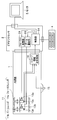
- FIG. 1 is a block diagram showing the configuration of an imaging system.
- This imaging system is for observing a subject in a dark place, and includes an endoscope 1, a video processor 2, and a light source device 3.
- the imaging system is configured as an endoscope system. It has become.
- the endoscope 1 includes an imaging optical system 11, an imaging unit 12, a lens driving unit 13, and a light guide 14.
- the imaging optical system 11 forms an optical image of the subject and is an optical system having a variable focus position equipped with a focus lens and the like.
- the imaging optical system 11 may be an optical system that further includes a zoom lens or the like and that can change the zoom position.
- the imaging unit 12 captures an optical image formed by the imaging optical system 11 and outputs an image. At this time, the exposure time when the imaging unit 12 captures an image is variable based on, for example, control of the control unit 24 described later.
- the lens driving unit 13 drives the imaging optical system 11 to change the focus position and the like. Specifically, the lens driving unit 13 changes the focus position by driving the focus lens, and a zoom lens is provided. If so, the zoom position is changed by driving the zoom lens.
- the light guide 14 transmits the illumination light supplied from the light source device 3 to the distal end of the insertion portion of the endoscope 1.
- the transmitted illumination light is irradiated from the distal end of the insertion portion of the endoscope 1 to the subject in the dark place.
- the video processor 2 controls and drives the endoscope 1 and processes an image obtained from the endoscope 1, and includes an amplification unit 21, an image processing unit 22, a control unit 24, and a contrast AF unit 26. And an auxiliary AF unit 27.
- the amplification unit 21 amplifies the image output from the imaging unit 12 in accordance with a set amplification factor.
- the image processing unit 22 performs various images such as color signal processing, color space conversion processing, edge enhancement processing, noise reduction processing, whiteout prevention processing, white balance processing, and ⁇ conversion on the image signal amplified by the amplification unit 21. Processing is performed.
- the image processed by the image processing unit 22 is output to a monitor or a recording device.
- the image processing unit 22 further includes a brightness detection unit 23 that detects the brightness of the image.
- the control unit 24 controls each unit in the video processor 2 and also controls the endoscope 1 and the light source device 3, and includes, for example, a CPU. That is, the control unit 24 sets the amplification factor, causes the amplification unit 21 to amplify the image, controls the image processing unit 22 to perform the above-described various image processing, and controls the auxiliary AF unit 27.
- a range that includes the temporary in-focus position obtained as a result of the auxiliary AF and that is narrower than the entire scan range is set as the contrast AF scan range, and the contrast AF in the set scan range is performed. To the contrast AF unit 26.
- the control unit 24 includes a brightness adjustment unit 25 that adjusts the brightness of the image based on the brightness control condition.
- the brightness adjustment unit 25 automatically adjusts the brightness of the image detected by the brightness detection unit 23 to be, for example, a predetermined brightness.
- the brightness control conditions are a light amount condition of illumination light supplied by the light source device 3, an exposure time of the imaging unit 12, an amplification factor in the amplification unit 21, and the like.
- the contrast AF unit 26 causes the imaging unit 12 to acquire a plurality of (generally three or more) images while changing the focus position within the scan range set by the control unit 24, and the contrast evaluation value of each acquired image And the focus position is adjusted so that the contrast evaluation value takes a peak value.
- the auxiliary AF unit 27 estimates the temporary in-focus position of the optical image of the subject based on the brightness of the image (and further based on the brightness control condition if necessary). Specifically, when the brightness adjustment unit 25 automatically adjusts the brightness of the image to a predetermined brightness, the auxiliary AF unit 27 sets the brightness control condition when the brightness of the image is the predetermined brightness. Based on the above, the temporary in-focus position of the optical image of the subject is estimated.
- the light source device 3 supplies illumination light for irradiating a subject in a dark place with, for example, variable light quantity, and includes a power supply 31, a current control unit 32, a light source 33, a light quantity diaphragm 34, and a light quantity.
- An aperture drive unit 35 and a collimator lens 36 are provided.
- the power supply 31 supplies a current to each part in the light source device 3, and supplies a current to the current control unit 32 and the light quantity diaphragm drive unit 35, for example.
- the current control unit 32 controls the current supplied to the light source 33 based on the control of the control unit 24 described above.
- the light source 33 emits light when supplied with current from the current control unit 32, and includes, for example, a lamp such as a halogen lamp, a xenon lamp, or a metal halide lamp, or a semiconductor light emitting element such as an LED.
- a lamp such as a halogen lamp, a xenon lamp, or a metal halide lamp
- a semiconductor light emitting element such as an LED
- the above-described current control unit 32 is configured to control the amount of illumination light by pulse width control (so-called PWM). Is done.
- PWM pulse width control
- the pulse width in the pulse width control of the current control unit 32 is one of the light quantity conditions described above.
- the light quantity diaphragm 34 is for controlling the quantity of illumination light.
- the aperture value of the light amount diaphragm 34 is one of the light amount conditions described above.
- the light amount diaphragm drive unit 35 drives and controls the light amount diaphragm 34 so that the aperture value specified by the light amount condition is obtained.
- the collimator lens 36 converts the illumination light emitted from the light source 33 and having a predetermined light amount through the light amount diaphragm 34 into a parallel light beam and irradiates the incident end of the light guide 14.
- FIG. 2 is a diagram showing an example of setting a scan range in contrast AF based on a brightness control condition when the brightness of an image becomes a predetermined brightness
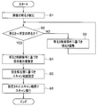
- FIG. 3 is a flowchart showing an operation of the imaging system. It is.
- the brightness detection unit 23 detects the brightness of the image (step S1).
- control unit 24 determines whether or not the detected brightness is a predetermined brightness (step S2).
- the brightness adjusting unit 25 adjusts the brightness of the image based on the brightness control condition (step S3). Specifically, when the image is darker than the predetermined brightness, the brightness adjustment unit 25 increases the aperture of the light amount diaphragm 34 (decreases the aperture value) and increases the pulse width of the pulse width control.
- the image is adjusted to have a predetermined brightness by performing at least one of, for example, increasing the exposure time of 12 and increasing the amplification factor in the amplification unit 21. Further, the brightness adjustment unit 25 performs the reverse adjustment when the image is brighter than the predetermined brightness.
- the auxiliary AF unit 27 When it is determined in step S2 that the brightness is predetermined, the auxiliary AF unit 27 temporarily focuses the optical image of the subject based on the brightness control condition when the brightness reaches the predetermined brightness. The position is estimated (step S4).
- the brightness control condition for adjusting the brightness of the image is the aperture value of the light amount aperture 34, and the brightness adjustment unit 25 adjusts the image to a predetermined brightness by changing the aperture value.
- the brightness control condition is not only the aperture value but the pulse width in the pulse width control, the exposure time of the imaging unit 12, the amplification factor in the amplification unit 21, and the like as described above, or a combination thereof. In this case, the same processing may be performed.
- the amount of illumination light supplied from the light source device 3 to the endoscope 1 is kept constant, the amount of illumination light irradiated to the subject is from the distal end surface of the insertion portion of the endoscope 1 to the subject. For example, it is inversely proportional to the square of the subject distance. Therefore, the brightness of the subject in the dark where the imaging system of the present embodiment is the observation target, and hence the brightness of the image obtained by imaging the subject, changes according to the subject distance.
- the specimen distance is expressed as a function of image brightness.
- the imaging system is provided with, for example, an automatic light control system for always imaging a subject with a constant brightness.
- the brightness adjusting unit 25 and the like have a function of the automatic light control system.
- the light quantity of the illumination light supplied from the light source device 3 increases because the aperture of the light quantity stop 34 is large if the aperture value is small. If the value is large, the amount of illumination light supplied from the light source device 3 is small because the aperture of the light amount diaphragm 34 is small.
- the brightness adjustment unit 25 reduces the aperture value to increase the amount of illumination light when the subject is far away and the brightness of the image is darker than the predetermined brightness, and the subject is close to the image. If the brightness is higher than the predetermined brightness, the aperture value is increased to reduce the amount of illumination light.
- the auxiliary AF unit 27 obtains the aperture value when the predetermined brightness is obtained in this way from the brightness control unit 24.
- the object distance is expressed as a function of the image brightness, and the image brightness is expressed as a function of the aperture value. That is, the object distance is expressed as a function of the aperture value ( More generally, as described above, the object distance is expressed by a multivariable function of the brightness control condition).
- This aperture value-distance graph shows how the illumination light quantity is reduced by increasing the aperture value (decreasing the aperture diameter of the light quantity diaphragm 34) as the subject distance approaches.
- the auxiliary AF unit 27 calculates a distance corresponding to the aperture value when the image has a predetermined brightness.
- the calculated distance is P1.
- the auxiliary AF unit 27 sets P1 calculated in this way as a temporary in-focus position.
- the auxiliary AF unit 27 determines that the scan range in the contrast AF is narrower than the entire scan range, for example, P2 to P3 so as to include the calculated temporary in-focus position P1 (step S5).
- the scan ranges P2 to P3 may be determined so as to be within a predetermined range on the near distance side and the far distance side with the provisional focus position P1 as the center, but if determined in consideration of other conditions, Even better.
- the predetermined range is increased.
- the predetermined range may be reduced.
- the predetermined range on the short distance side from the temporary focusing position is set to a predetermined range on the long distance side from the temporary focusing position. It may be made larger than the range.
- the contrast AF unit 26 receives information on the scan ranges P2 to P3 determined by the auxiliary AF unit 27, and from the current focus position P0, an appropriate scan start position within the scan ranges P2 to P3, here the focus position P0.
- the focus position is moved to P2 closest to the position (however, the movement to the scan start position may be performed by the auxiliary AF unit 27, and then the scan by the contrast AF unit 26 may be started). Since this position P2 is the farthest point in the scan range P2 to P3, the scan is started toward the short distance side, the contrast evaluation value gradually increases, and the scan direction is changed when it starts to decrease. By reversing, the focus position can be adjusted to the true in-focus position P4 where the contrast evaluation value takes the peak value (step S6).
- the auxiliary AF The unit 27 can estimate the temporary in-focus position based on the brightness of the image. Therefore, the estimation of the temporary in-focus position by the auxiliary AF unit 27 is not limited to using the brightness control condition when the image has a predetermined brightness.
- the temporary focus position is detected by performing the auxiliary AF (brightness AF) before the contrast AF is performed, and the scan range or the contrast AF in the contrast AF is detected based on the detected temporary focus position.
- the scan start position is determined.
- the determined scanning range is narrower than the entire scanning range, it is possible to shorten the time until focusing in contrast AF. Since the final focus position is obtained by contrast AF, it is possible to detect the focus with high accuracy.
- auxiliary AF since brightness AF based on an image acquired from the imaging unit 12 is used as auxiliary AF before performing contrast AF, for example, a phase difference AF sensor such as a case where phase difference AF is used as auxiliary AF.
- This configuration is unnecessary, and there is an advantage that it is suitable for the field of endoscopes and the like that require a reduction in size and diameter.
- the imaging optical system 11 is an optical system that includes a focus lens and a zoom lens and has a variable focus position and zoom position, a switch for moving the focus position to the near side, a focus position
- a switch for moving the lens to the far (far) side there are a total of four switches: a switch for moving the lens to the far (far) side, a switch for moving the zoom position to the tele (telephoto) side, and a switch for moving the zoom position to the wide (wide angle) side.
- the structure provided in the operation part of the endoscope 1 has been conventionally employed. However, in this configuration, since the number of switches is large, the operation is complicated for the operator. In addition, while using the imaging system, it is difficult to grasp the focus state and zoom state of the current image only from the observed image, and there is room for improvement in usability.
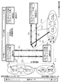
- FIG. 4 is a diagram showing a configuration of an imaging system including a focus / zoom switch.
- the imaging system includes an endoscope 1 and a video processor 2, and further includes an operation unit 4 and a monitor 5.
- the imaging system is configured as an endoscope system.
- the light source device 3 is further provided.
- the imaging optical system 11 of the endoscope 1 includes a focus lens 11a and a zoom lens 11b.
- the focus lens 11a is driven by an actuator 13a
- the zoom lens 11b is driven by an actuator 13b.
- the drive position of the focus lens 11a, and hence the focus position are detected by the position detector 13c
- the drive position of the zoom lens 11b, and consequently the zoom position are detected by the position detector 13d.
- various methods such as a method using a position sensor, a method of detecting an actuator resistance value, and a method based on a count value of the number of drive pulses can be appropriately employed. .
- an operation unit of the endoscope 1 is provided with a switch 15 that is a focus / zoom switch that performs both a focus operation and a zoom operation.
- the switch 15 is configured as, for example, a push operation type push button switch.
- the focus position information detected by the position detection unit 13c, the zoom position information detected by the position detection unit 13d, and the switch operation information from the switch 15 are provided in, for example, the operation unit of the endoscope 1. It is transmitted to the control unit 24 of the video processor 2 via the scope information transmitting / receiving unit 16.
- the video processor 2 is provided with a focus driving unit 28 and a zoom driving unit 29 in addition to the control unit 24.
- the focus drive unit 28 adjusts the focus position by driving the actuator 13a and moving the focus lens 11a in the optical axis direction based on the control of the control unit 24 that has obtained the focus position and switch operation information.
- the zoom drive unit 29 adjusts the zoom position by driving the actuator 13b and moving the zoom lens 11b in the optical axis direction based on the control of the control unit 24 that has obtained the zoom position and switch operation information.
- the operation unit 4 is connected to the control unit 24 and is configured to be able to set a priority mode related to the switch 15 and perform various other operation inputs.
- the priority mode related to the switch 15 includes a focus priority mode in which the focus function is prioritized and a zoom priority in which the zoom function is prioritized as an initial function of the switch 15 such as immediately after power-on or after a switch function reset.
- the focus function of this configuration example is a so-called two-focus switching that switches only two points, a seamless operation that can continuously change the focus position, and the focus position near and normal (a focus position that is farther than the near).
- the focus function is also selected by the operation unit 4.
- the control unit 24 is further connected to the monitor 5.
- the monitor 5 displays an image acquired from the endoscope 1 and further displays each information of the priority mode, the focus position, and the zoom position under the control of the control unit 24.
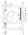
- FIG. 5 is a diagram showing a display example of the monitor 5.
- an endoscope image 51 is displayed at the center.
- a priority mode display 52 including a focus priority mode display 52a and a zoom priority mode display 52b is displayed on the upper left of the screen 5a, for example.
- the focus priority mode display is displayed. 52a is highlighted, indicating that the switch 15 is currently set to the focus priority mode.
- a focus position display 53 including a normal focus position display 53a and a near focus position display 53b is displayed on the upper right portion of the screen 5a, for example.
- the near focus position display is displayed. 53b is highlighted, indicating that the focus lens 11a is currently in the near focus position.
- a zoom position including a zoom position bar 54a, a wide position display 54b, a tele position display 54c, an index 54d, a wide direction display 54e, and a tele direction display 54f, for example, on the lower side of the screen 5a.
- the indicator 54d is displayed in the middle of the wide position display 54b and the tele position display 54c slightly closer to the wide to indicate the current zoom position, and the wide direction display.
- 54e is highlighted, indicating that the moving direction when the zoom lens 11b moves is now the wide direction.
- the focus position is so-called bifocal switching that can take only two points of normal and near, but a seamless operation in which the focus position can be changed continuously.
- display similar to the zoom position display 54 described above may be performed.
- the display mode is not limited to the example shown in FIG.
- FIGS. 6 to 9 when the longitudinal direction of the drawing is viewed as the left and right direction, the left side is the wide side, the right side is the tele side, the upper side is the normal side, and the lower side is the near side.
- the figure is arranged.
- the zoom is described on the assumption that a seamless operation is performed.
- the present invention is not limited to this, and a configuration in which a plurality of focal lengths can be taken discontinuously may be used.
- FIG. 6 is a diagram illustrating the operation of the imaging system in the focus priority mode when the focus is bifocal switching.
- the image state A is the focus at the normal end and the zoom is at the wide end
- the image state B is the focus at the near end
- the zoom is at the wide end
- the image state C is the focus at the normal end and the zoom is at the tele end.
- the image state D is a state where the focus is the near end and the zoom is the tele end.
- the image state C is not used in the focus priority mode as shown in FIG.
- the image state A is switched to the initial state. This image state A is suitable for full-view observation.
- image state A when switch 15 is pressed for a short time, it switches to image state B as shown by arrow ⁇ 1.
- the image state A when the switch 15 is pressed for a short time, the image state A is switched as indicated by the arrow ⁇ 2.
- the zoom direction is switched as shown by an arrow ⁇ 7.
- the function of the switch 15 is switched to the zoom wide direction when the switch 15 is pressed shortly in the zoom telephoto direction, and is switched to the zoom telephoto direction when the switch 15 is short pressed in the zoom wide direction.
- the operation of “two consecutive short presses” indicated by the white arrow is performed by the switch 15. Once done, return to image state A. Therefore, the same panoramic view as when the power is turned on can be quickly performed with a simple operation.
- the function of the switch 15 as a zoom switch is disabled by the processing in the CPU, and the state of functioning as a focus switch is entered.
- FIG. 7 is a diagram illustrating the operation of the imaging system in the focus priority mode when the focus is a seamless operation.
- the image states A to C are the same as described above.
- the focus is between the normal end and the near end, and the zoom is in the wide end (between the image state A and the image state B).
- the image state (BC) is a state in which the focus is between the normal end and the near end, and the zoom is in the tele end.
- the image state C is not used even in the focus priority mode when the focus is a seamless operation as shown in FIG.
- the image state A is switched to the initial state.
- the function of the switch 15 is to switch to the focus normal direction when the switch 15 is pressed shortly in the focus near direction, and to the focus near direction when the switch 15 is pressed shortly in the focus normal direction.
- the zoom state changes to the tele direction while the switch 15 is pressed and held.
- the change of the zoom state in the tele direction becomes the tele end when the image state (BC) is reached and does not proceed any further.
- the switch 15 When the function of the switch 15 is in the zoom wide direction as shown by the arrow ⁇ 9 in the image state (BC) or between the image state (B) and the image state (BC), the switch 15 is long. While pressed, the zoom status changes in the wide direction.
- the zoom direction is switched as indicated by an arrow ⁇ 10.
- the function of the switch 15 is switched to the zoom wide direction when the switch 15 is short-pressed in the zoom telephoto direction, and is switched to the zoom telephoto direction when the switch 15 is short-pressed in the zoom wide direction.
- FIG. 8 is a diagram illustrating the operation of the imaging system in the zoom priority mode when the focus is bifocal switching.
- the image states A to C are the same as described above, and the image state (C) is the state where the focus is at the normal end and the zoom is between the wide end and the tele end (between the image state A and the image state C).
- the image state (CB) is a state where the focus is at the near end and the zoom is between the wide end and the tele end. Note that the image state B is not used in the zoom priority mode when the focus is two-focus switching as shown in FIG.
- the image state A is switched to the initial state.
- the switch 15 When the function of the switch 15 is in the zoom telephoto direction in the state between the image state A or the image state A and the image state C, when the switch 15 is pressed long, the switch 15 is pressed as shown by the arrow ⁇ 1. The zoom state changes in the tele direction while the camera is on.
- the function of the switch 15 is switched to the zoom wide direction when the switch 15 is pressed shortly in the zoom telephoto direction, and switched to the zoom telephoto direction when the switch 15 is pressed shortly in the zoom wide direction.
- the zoom state is released by the processing in the CPU, and the switch 15 functions as a zoom switch, and the zoom switch function is set in the zoom telephoto direction.
- the zoom state is released only by performing an operation of “two consecutive short presses”.
- FIG. 9 is a diagram illustrating the operation of the imaging system in the zoom priority mode when the focus is a seamless operation.
- the image states A to C, (C), and (CB) are the same as described above. Note that the image state B is not used even in the zoom priority mode when the focus is a seamless operation as shown in FIG.
- the image state A is switched to the initial state.
- the switch 15 When the function of the switch 15 is in the zoom telephoto direction in the state between the image state A or the image state A and the image state C, when the switch 15 is pressed long, the switch 15 is pressed as shown by the arrow ⁇ 1. The zoom state changes in the tele direction while the camera is on.
- the function of the switch 15 is the zoom wide direction in the state between the image state C or the image state A and the image state C, pressing the switch 15 will cause the switch 15 to be pressed as shown by the arrow ⁇ 2.
- the zoom state changes in the wide direction during
- the function of the switch 15 is the zoom telephoto direction or the zoom wide direction
- the switch 15 is pressed for a short time, the focus direction is switched as shown by the arrow ⁇ 3.
- the function of the switch 15 is switched to the zoom wide direction when the switch 15 is short-pressed in the zoom telephoto direction, and switched to the zoom telephoto direction when the switch 15 is short-pressed in the zoom wide direction.
- the function of the switch 15 is to switch to the focus normal direction when the switch 15 is pressed shortly in the focus near direction, and to the focus near direction when the switch 15 is pressed shortly in the focus normal direction.
- the state returns to the image state A.
- the zoom state is released by the processing in the CPU, and the switch 15 functions as a zoom switch, and the zoom switch function is set in the zoom telephoto direction.
- the focus switch function is set in the near direction. It should be noted that once the zoom state is fixed by the processing in the CPU, the zoom state is released only by performing an operation of “two consecutive short presses”.
- the switch 15 is of a type that can detect a pressing force or the like, for example, a strong / weak push operation of the switch 15 is employed instead of the long push / short push operation of the switch 15 described above. You may do it.
- the operation conventionally performed by four switches can be performed by one switch, so the troublesome operation of a plurality of switches is eliminated, The operability of the endoscope 1 can be improved.
- the reduction in the number of switches can contribute to the miniaturization of the endoscope 1.
- the focus is automatically set to the normal end and the zoom is set to the wide end when the power is turned on, it is possible to perform a full view observation without requiring a separate operation.
- the priority mode display 52 is displayed on the monitor 5, the state of the switch 15 can be grasped. Further, since the focus position display 53 is displayed on the monitor 5, the focus state can be always grasped. In addition, since the zoom position display 54 is displayed on the monitor 5, the zoom state can be always grasped. Thus, the surgeon can easily grasp the state of the endoscope 1 at the time of observation.
- an imaging system operation method may be used, a processing program for causing a computer to execute the imaging system operation method, and a computer that records the processing program can be read. It may be a recording medium that is not temporary.
- the present invention is not limited to the above-described embodiment as it is, and can be embodied by modifying the constituent elements without departing from the scope of the invention in the implementation stage.
- various aspects of the invention can be formed by appropriately combining a plurality of components disclosed in the embodiment. For example, you may delete some components from all the components shown by embodiment.
- the constituent elements over different embodiments may be appropriately combined.
Landscapes
- Physics & Mathematics (AREA)
- Life Sciences & Earth Sciences (AREA)
- Health & Medical Sciences (AREA)
- Engineering & Computer Science (AREA)
- Surgery (AREA)
- Optics & Photonics (AREA)
- Biomedical Technology (AREA)
- Molecular Biology (AREA)
- Veterinary Medicine (AREA)
- Biophysics (AREA)
- Nuclear Medicine, Radiotherapy & Molecular Imaging (AREA)
- Pathology (AREA)
- Radiology & Medical Imaging (AREA)
- Public Health (AREA)
- Multimedia (AREA)
- Heart & Thoracic Surgery (AREA)
- Medical Informatics (AREA)
- General Health & Medical Sciences (AREA)
- Animal Behavior & Ethology (AREA)
- General Physics & Mathematics (AREA)
- Signal Processing (AREA)
- Astronomy & Astrophysics (AREA)
- Computer Vision & Pattern Recognition (AREA)
- Mechanical Engineering (AREA)
- Automatic Focus Adjustment (AREA)
- Studio Devices (AREA)
- Endoscopes (AREA)
- Focusing (AREA)
Abstract
Description
図1から図3は本発明の実施形態1を示したものであり、図1は撮像システムの構成を示すブロック図である。
Claims (8)
- 暗所にある被検体に対して照射する照明光を供給する光源装置と、
前記被検体の光学像を結像するものであり、フォーカス位置が可変な結像光学系と、
前記光学像を撮像して画像を出力する撮像部と、
前記画像の明るさを検出する明るさ検出部と、
前記明るさ検出部により検出される前記画像の明るさに基づいて、前記光学像の仮合焦位置を推定する補助AF部と、
前記仮合焦位置を含み全スキャン範囲よりも狭い範囲を、コントラストAFのスキャン範囲として設定する制御部と、
前記スキャン範囲内で前記フォーカス位置を変化させながら前記撮像部に複数の画像を取得させ、取得された各画像のコントラスト評価値を算出して、前記コントラスト評価値がピーク値を取るように前記フォーカス位置を調整するコントラストAF部と、
を具備したことを特徴とする撮像システム。 - 明るさ制御条件を調整して前記明るさ検出部により検出される前記画像の明るさが所定の明るさとなるようにする明るさ調整部と、
前記補助AF部は、前記画像の明るさが前記所定の明るさであるときの前記明るさ制御条件に基づいて、前記光学像の仮合焦位置を推定することを特徴とする請求項1に記載の撮像システム。 - 前記光源装置は、前記照明光を光量可変に供給するものであり、
前記明るさ制御条件は、前記光源装置が供給する前記照明光の光量条件であることを特徴とする請求項2に記載の撮像システム。 - 前記光源装置は、前記照明光の光量を制御するための光量絞りを有し、
前記光量条件は、前記光量絞りの絞り値であることを特徴とする請求項3に記載の撮像システム。 - 前記光源装置は、パルス幅制御により前記照明光の光量を制御するように構成されており、
前記光量条件は、前記パルス幅制御におけるパルス幅であることを特徴とする請求項3に記載の撮像システム。 - 前記撮像部は、露光時間を可変とするように構成されており、
前記明るさ制御条件は、前記露光時間であることを特徴とする請求項2に記載の撮像システム。 - 前記撮像部から出力される画像を増幅率に応じて信号増幅する増幅部をさらに具備し、
前記明るさ制御条件は、前記増幅率であることを特徴とする請求項2に記載の撮像システム。 - 光源装置が、暗所にある被検体に対して照射する照明光を供給するステップと、
フォーカス位置が可変な結像光学系が結像した前記被検体の光学像を、撮像部が撮像して画像を出力するステップと、
明るさ検出部が、前記画像の明るさを検出するステップと、
補助AF部が、前記明るさ検出部により検出される前記画像の明るさに基づいて、前記光学像の仮合焦位置を推定するステップと、
制御部が、前記仮合焦位置を含み全スキャン範囲よりも狭い範囲を、コントラストAFのスキャン範囲として設定するステップと、
コントラストAF部が、前記スキャン範囲内で前記フォーカス位置を変化させながら前記撮像部に複数の画像を取得させ、取得された各画像のコントラスト評価値を算出して、前記コントラスト評価値がピーク値を取るように前記フォーカス位置を調整するステップと、
を有する撮像システムの作動方法。
Priority Applications (4)
| Application Number | Priority Date | Filing Date | Title |
|---|---|---|---|
| EP14857563.2A EP3067727A4 (en) | 2013-10-31 | 2014-10-23 | Imaging system and imaging system operation method |
| JP2015525660A JP5857160B2 (ja) | 2013-10-31 | 2014-10-23 | 内視鏡用の撮像システム、内視鏡用の撮像システムの作動方法 |
| CN201480050144.6A CN105579880B (zh) | 2013-10-31 | 2014-10-23 | 内窥镜用摄像系统、内窥镜用摄像系统的工作方法 |
| US15/069,320 US9621814B2 (en) | 2013-10-31 | 2016-03-14 | Image pickup for endoscope and method for operating image pickup system for endoscope |
Applications Claiming Priority (2)
| Application Number | Priority Date | Filing Date | Title |
|---|---|---|---|
| JP2013227253 | 2013-10-31 | ||
| JP2013-227253 | 2013-10-31 |
Related Child Applications (1)
| Application Number | Title | Priority Date | Filing Date |
|---|---|---|---|
| US15/069,320 Continuation US9621814B2 (en) | 2013-10-31 | 2016-03-14 | Image pickup for endoscope and method for operating image pickup system for endoscope |
Publications (1)
| Publication Number | Publication Date |
|---|---|
| WO2015064462A1 true WO2015064462A1 (ja) | 2015-05-07 |
Family
ID=53004068
Family Applications (1)
| Application Number | Title | Priority Date | Filing Date |
|---|---|---|---|
| PCT/JP2014/078188 WO2015064462A1 (ja) | 2013-10-31 | 2014-10-23 | 撮像システム、撮像システムの作動方法 |
Country Status (5)
| Country | Link |
|---|---|
| US (1) | US9621814B2 (ja) |
| EP (1) | EP3067727A4 (ja) |
| JP (1) | JP5857160B2 (ja) |
| CN (1) | CN105579880B (ja) |
| WO (1) | WO2015064462A1 (ja) |
Cited By (2)
| Publication number | Priority date | Publication date | Assignee | Title |
|---|---|---|---|---|
| JP2017012666A (ja) * | 2015-07-06 | 2017-01-19 | オリンパス株式会社 | 内視鏡検査データ記録システム |
| JP2017012665A (ja) * | 2015-07-06 | 2017-01-19 | オリンパス株式会社 | 内視鏡検査データ記録システム |
Families Citing this family (9)
| Publication number | Priority date | Publication date | Assignee | Title |
|---|---|---|---|---|
| CN105939451B (zh) * | 2016-06-23 | 2018-10-02 | 安翰光电技术(武汉)有限公司 | 用于胶囊内窥镜系统的图像曝光处理系统及方法 |
| CN106161970B (zh) * | 2016-09-26 | 2019-10-11 | 宇龙计算机通信科技(深圳)有限公司 | 一种拍摄方法、装置以及移动终端 |
| CN106506973B (zh) * | 2016-12-06 | 2020-02-04 | Oppo广东移动通信有限公司 | 对焦控制方法、装置、电子设备及终端设备 |
| CN111095067B (zh) * | 2017-09-20 | 2022-03-01 | 富士胶片株式会社 | 摄像装置、摄像装置主体及摄像装置的对焦控制方法 |
| JP7093409B2 (ja) * | 2018-06-05 | 2022-06-29 | オリンパス株式会社 | 内視鏡システム |
| CN112367898B (zh) * | 2018-07-10 | 2024-09-24 | 奥林巴斯株式会社 | 内窥镜装置和内窥镜装置的工作方法 |
| WO2020026493A1 (ja) * | 2018-07-30 | 2020-02-06 | オリンパス株式会社 | 内視鏡装置、駆動方法およびプログラム |
| DE102022109399A1 (de) | 2022-04-19 | 2023-10-19 | Schölly Fiberoptic GmbH | Assistiertes Autofokus-Verfahren und zugehöriges optisches Abbildungssystem |
| DE102022109398A1 (de) | 2022-04-19 | 2023-10-19 | Schölly Fiberoptic GmbH | Autofokus-Verfahren und zugehöriges optisches Abbildungssystem |
Citations (5)
| Publication number | Priority date | Publication date | Assignee | Title |
|---|---|---|---|---|
| JP2006023652A (ja) * | 2004-07-09 | 2006-01-26 | Canon Inc | 撮像装置及びその制御方法 |
| JP2006324985A (ja) * | 2005-05-19 | 2006-11-30 | Olympus Corp | 撮像装置 |
| JP2008111897A (ja) | 2006-10-30 | 2008-05-15 | Canon Inc | オートフォーカス装置および撮像装置 |
| JP2009133903A (ja) | 2007-11-28 | 2009-06-18 | Fujifilm Corp | 撮像装置およびその撮像方法 |
| JP2009186894A (ja) * | 2008-02-08 | 2009-08-20 | Panasonic Corp | 電子カメラ及び電子カメラ用ストロボ装置 |
Family Cites Families (12)
| Publication number | Priority date | Publication date | Assignee | Title |
|---|---|---|---|---|
| JP4264920B2 (ja) * | 2001-06-22 | 2009-05-20 | ソニー株式会社 | デジタルカメラの露出制御方法および露出制御装置 |
| JP2006072384A (ja) * | 2005-10-31 | 2006-03-16 | Fuji Photo Film Co Ltd | 自動焦点調節装置及び方法 |
| EP2055224A1 (en) * | 2007-10-31 | 2009-05-06 | Orangedental GmbH & Co. KG | Autofocus method and system therefor |
| JP5669529B2 (ja) * | 2010-11-17 | 2015-02-12 | オリンパス株式会社 | 撮像装置、プログラム及びフォーカス制御方法 |
| JP2012125293A (ja) * | 2010-12-13 | 2012-07-05 | Olympus Corp | 制御装置、内視鏡装置及びフォーカス制御方法 |
| JP5948076B2 (ja) * | 2011-08-23 | 2016-07-06 | オリンパス株式会社 | フォーカス制御装置、内視鏡装置及びフォーカス制御方法 |
| JP2013076823A (ja) * | 2011-09-30 | 2013-04-25 | Olympus Corp | 画像処理装置、内視鏡システム、画像処理方法及びプログラム |
| JP5953187B2 (ja) * | 2011-10-11 | 2016-07-20 | オリンパス株式会社 | 合焦制御装置、内視鏡システム及び合焦制御方法 |
| JP5973708B2 (ja) * | 2011-10-21 | 2016-08-23 | オリンパス株式会社 | 撮像装置及び内視鏡装置 |
| JP5889010B2 (ja) * | 2012-01-31 | 2016-03-22 | キヤノン株式会社 | 撮像装置およびその制御方法 |
| JP5996218B2 (ja) * | 2012-03-07 | 2016-09-21 | オリンパス株式会社 | 内視鏡装置及び内視鏡装置の作動方法 |
| US9692954B2 (en) * | 2013-03-28 | 2017-06-27 | General Electric Company | Methods and devices for adjusting brightness of a light source |
-
2014
- 2014-10-23 WO PCT/JP2014/078188 patent/WO2015064462A1/ja active Application Filing
- 2014-10-23 CN CN201480050144.6A patent/CN105579880B/zh active Active
- 2014-10-23 JP JP2015525660A patent/JP5857160B2/ja active Active
- 2014-10-23 EP EP14857563.2A patent/EP3067727A4/en not_active Withdrawn
-
2016
- 2016-03-14 US US15/069,320 patent/US9621814B2/en active Active
Patent Citations (5)
| Publication number | Priority date | Publication date | Assignee | Title |
|---|---|---|---|---|
| JP2006023652A (ja) * | 2004-07-09 | 2006-01-26 | Canon Inc | 撮像装置及びその制御方法 |
| JP2006324985A (ja) * | 2005-05-19 | 2006-11-30 | Olympus Corp | 撮像装置 |
| JP2008111897A (ja) | 2006-10-30 | 2008-05-15 | Canon Inc | オートフォーカス装置および撮像装置 |
| JP2009133903A (ja) | 2007-11-28 | 2009-06-18 | Fujifilm Corp | 撮像装置およびその撮像方法 |
| JP2009186894A (ja) * | 2008-02-08 | 2009-08-20 | Panasonic Corp | 電子カメラ及び電子カメラ用ストロボ装置 |
Non-Patent Citations (1)
| Title |
|---|
| See also references of EP3067727A4 |
Cited By (2)
| Publication number | Priority date | Publication date | Assignee | Title |
|---|---|---|---|---|
| JP2017012666A (ja) * | 2015-07-06 | 2017-01-19 | オリンパス株式会社 | 内視鏡検査データ記録システム |
| JP2017012665A (ja) * | 2015-07-06 | 2017-01-19 | オリンパス株式会社 | 内視鏡検査データ記録システム |
Also Published As
| Publication number | Publication date |
|---|---|
| CN105579880B (zh) | 2018-06-26 |
| EP3067727A4 (en) | 2017-11-22 |
| CN105579880A (zh) | 2016-05-11 |
| US20160198076A1 (en) | 2016-07-07 |
| JP5857160B2 (ja) | 2016-02-10 |
| JPWO2015064462A1 (ja) | 2017-03-09 |
| EP3067727A1 (en) | 2016-09-14 |
| US9621814B2 (en) | 2017-04-11 |
Similar Documents
| Publication | Publication Date | Title |
|---|---|---|
| JP5857160B2 (ja) | 内視鏡用の撮像システム、内視鏡用の撮像システムの作動方法 | |
| EP2749923B1 (en) | Focus control device, endoscope device, and focus control method | |
| US6999684B2 (en) | Camera system and camera | |
| US10129454B2 (en) | Imaging device, endoscope apparatus, and method for controlling imaging device | |
| US8754979B2 (en) | Focus adjustment device and imaging device | |
| JP5988590B2 (ja) | 内視鏡装置 | |
| US20120147165A1 (en) | Control device, endoscope apparatus, and focus control method | |
| US9277111B2 (en) | Image capture apparatus and control method therefor | |
| JP5022580B2 (ja) | 内視鏡装置 | |
| US11509816B2 (en) | Image processing apparatus, image pickup apparatus, and control method of image processing apparatus | |
| US10348955B2 (en) | Imaging apparatus, control method, and storage medium for tracking an imaging target in a continuous shooting operation | |
| US8233075B2 (en) | User-aided auto-focus | |
| JP2014083352A (ja) | 撮影装置及び撮影装置における合焦方法 | |
| JP2013186293A (ja) | 画像生成装置および画像表示方法 | |
| WO2013061939A1 (ja) | 内視鏡装置及びフォーカス制御方法 | |
| JP2013042300A (ja) | 撮像装置及びフリッカー発生周波数検出方法 | |
| JP2011147043A (ja) | 口腔内カメラと、その照明の制御方法 | |
| JP2016114836A (ja) | フォーカス制御装置、光学機器およびフォーカス制御方法 | |
| JP2019095807A (ja) | 焦点検出装置および撮像装置 | |
| JP2020003759A (ja) | 焦点調節装置およびその制御方法 | |
| JP2015064521A (ja) | 焦点検出装置、焦点調節装置、および撮像装置 | |
| JP2005024858A (ja) | デジタル一眼レフカメラ | |
| JP2022050280A (ja) | 撮像制御装置、内視鏡システム、および撮像制御方法 | |
| JP2016061802A (ja) | 撮像システム、照明装置及び制御方法 | |
| JP2014164288A (ja) | 撮像装置 |
Legal Events
| Date | Code | Title | Description |
|---|---|---|---|
| WWE | Wipo information: entry into national phase |
Ref document number: 201480050144.6 Country of ref document: CN |
|
| ENP | Entry into the national phase |
Ref document number: 2015525660 Country of ref document: JP Kind code of ref document: A |
|
| 121 | Ep: the epo has been informed by wipo that ep was designated in this application |
Ref document number: 14857563 Country of ref document: EP Kind code of ref document: A1 |
|
| REEP | Request for entry into the european phase |
Ref document number: 2014857563 Country of ref document: EP |
|
| WWE | Wipo information: entry into national phase |
Ref document number: 2014857563 Country of ref document: EP |
|
| NENP | Non-entry into the national phase |
Ref country code: DE |