WO2015064396A1 - Steering device - Google Patents
Steering device Download PDFInfo
- Publication number
- WO2015064396A1 WO2015064396A1 PCT/JP2014/077732 JP2014077732W WO2015064396A1 WO 2015064396 A1 WO2015064396 A1 WO 2015064396A1 JP 2014077732 W JP2014077732 W JP 2014077732W WO 2015064396 A1 WO2015064396 A1 WO 2015064396A1
- Authority
- WO
- WIPO (PCT)
- Prior art keywords
- column
- lock member
- steering
- inner column
- fixed
- Prior art date
Links
Images


Classifications
-
- B—PERFORMING OPERATIONS; TRANSPORTING
- B62—LAND VEHICLES FOR TRAVELLING OTHERWISE THAN ON RAILS
- B62D—MOTOR VEHICLES; TRAILERS
- B62D1/00—Steering controls, i.e. means for initiating a change of direction of the vehicle
- B62D1/02—Steering controls, i.e. means for initiating a change of direction of the vehicle vehicle-mounted
- B62D1/16—Steering columns
- B62D1/18—Steering columns yieldable or adjustable, e.g. tiltable
- B62D1/19—Steering columns yieldable or adjustable, e.g. tiltable incorporating energy-absorbing arrangements, e.g. by being yieldable or collapsible
- B62D1/195—Yieldable supports for the steering column
-
- B—PERFORMING OPERATIONS; TRANSPORTING
- B62—LAND VEHICLES FOR TRAVELLING OTHERWISE THAN ON RAILS
- B62D—MOTOR VEHICLES; TRAILERS
- B62D1/00—Steering controls, i.e. means for initiating a change of direction of the vehicle
- B62D1/02—Steering controls, i.e. means for initiating a change of direction of the vehicle vehicle-mounted
- B62D1/16—Steering columns
- B62D1/18—Steering columns yieldable or adjustable, e.g. tiltable
- B62D1/184—Mechanisms for locking columns at selected positions
-
- B—PERFORMING OPERATIONS; TRANSPORTING
- B62—LAND VEHICLES FOR TRAVELLING OTHERWISE THAN ON RAILS
- B62D—MOTOR VEHICLES; TRAILERS
- B62D1/00—Steering controls, i.e. means for initiating a change of direction of the vehicle
- B62D1/02—Steering controls, i.e. means for initiating a change of direction of the vehicle vehicle-mounted
- B62D1/16—Steering columns
- B62D1/18—Steering columns yieldable or adjustable, e.g. tiltable
- B62D1/187—Steering columns yieldable or adjustable, e.g. tiltable with tilt adjustment; with tilt and axial adjustment
Definitions
- the present invention relates to a steering device.
- Patent Document 1 A technique using a capsule is widely known as a support structure of a steering device that gives a steering angle to a wheel as the steering wheel rotates.
- Patent Document 2 discloses a structure in which a telescopic fixing member slides when an impact load is generated. In this structure, since the fixing member is housed in the groove, it is necessary to lengthen the groove in order to increase the stroke amount, and the column tends to be enlarged.
- the present invention has been made in view of the above-described problem, and can suppress a situation in which a steering column falls due to a malfunction even when a set value of a separation load at which the steering column moves forward of a vehicle body is lowered.
- An object is to provide an apparatus.
- a steering device includes a cylindrical inner column that rotatably supports an input shaft connected to a steering wheel, and at least a part of the inner column inserted inside.
- An outer column having a slit cut out at one end on the insertion side of the inner column, and a column bracket fastened to the vehicle body side member and tightening the outer column with a pressing bracket sandwiching the outer column; , A pressed portion provided on the outer periphery of the inner column, a first fixing mechanism for tightening the outer column according to the rotation of the operation lever, and a tilt with respect to the pressed portion according to the rotation of the operation lever
- a second fixing mechanism for urging the lock member in the direction, and the first fixing mechanism tightens the outer column
- the inner column changes its relative position with the pressing bracket and can be detached. It is characterized by providing.
- the outer column is supported on the vehicle body via the vehicle body side member, and when a force is transmitted from the steering wheel to the steering column during the secondary collision, the inner column is inserted into the outer column. And stored in the outer column. In this case, the outer column remains fixed to the vehicle body. For this reason, even if the inner column is inserted into the outer column due to a malfunction, the steering column does not fall. Even if the pressure sandwiched between the column brackets is lowered and the friction force generated between the inner column and the outer column is lowered, the second fixing mechanism urges the lock member in the tilt direction with respect to the fixed plate portion, so The possibility of exceeding the separation load even when the load is other than the collision is reduced. For this reason, in order to relieve the impact of the secondary collision on the operator who is light in weight, the set value of the separation load at which the steering wheel moves forward of the vehicle body can be lowered.
- the pressed portion is a fixed plate portion that is disposed at least partially inside the slit of the outer column and is detachably fixed to the inner column.
- the operator's weight is light, it is better to lower the set value of the separation load at which the inner column of the steering column moves to the front of the vehicle body, and lower the pressure pinched by the column bracket so that it is between the inner column and the outer column. Reduce the resulting frictional force.
- the fixed plate portion can be detached from the inner column.
- the connection of the second fixing mechanism can be released, and the steering device receives the impact (secondary collision) of the operator with a light weight. ) Can be relaxed.
- the detachment mechanism includes a first hole of the fixing plate portion, a second hole of the inner column, and a shear pin provided so as to straddle the first hole and the second hole. It is preferable that the inner column and the fixing plate portion are detachably fixed.
- the shear pin receives a shearing force when the steering column is pushed forward of the vehicle body.
- the shear pin is broken, the connection between the fixing plate portion and the inner column is released, and the connection of the second fixing mechanism is released. For this reason, the force by which the second fixing mechanism urges the lock member in the tilt direction relative to the fixed plate portion is not transmitted.
- a tilt bolt that penetrates the pressing bracket and interlocks with the operation lever is provided, and the second fixing mechanism is provided at a position facing the slit of the outer column and interlocks with the tilt bolt. It is preferable to provide a rotating cam portion that rotates.
- the operations of the first fixing mechanism and the second fixing mechanism can be linked. Then, the operator can release the fixation of both the first fixing mechanism and the second fixing mechanism and adjust the tilt position and the telescopic position only by operating the operation lever. Further, the operator can fix both the first fixing mechanism and the second fixing mechanism by only operating the operation lever, and fix the tilt position and the telescopic position.
- the position of the lock member in the tilt direction relative to the fixed plate portion changes according to the rotation of the rotary cam portion. For this reason, the operator can release the fixation of the second fixing mechanism and adjust the tilt position and the telescopic position only by operating the operation lever. Further, the operator can fix the tilt position and the telescopic position by fixing the second fixing mechanism only by operating the operation lever.
- the rotating cam portion includes a tooth portion or an unevenness at a contact portion with the fixed plate portion. Accordingly, the second fixing mechanism is urged in the tilt direction with respect to the column bracket, and is securely fixed in the telescopic direction with respect to the fixing plate portion side.
- the lock member includes a first lock member and a second lock member that are divided in the tilt direction, and the detachment mechanism is configured to move against the first lock member that contacts the pressed portion. It is preferable that the second lock member is detachably fixed.
- the operator's weight is light, it is better to lower the set value of the separation load at which the inner column of the steering column moves to the front of the vehicle body, and lower the pressure pinched by the column bracket so that it is between the inner column and the outer column. Reduce the resulting frictional force.
- the first lock member and the second lock member can be separated.
- the connection of the second fixing mechanism can be released, and the steering device receives the impact (secondary collision) of the operator with a light weight. ) Can be relaxed.
- the separation mechanism is provided so as to straddle the first hole of the first lock member, the second hole of the second lock member, and the first hole and the second hole. It is preferable that the first lock member and the second lock member are detachably fixed.
- a tilt bolt that penetrates the pressing bracket and interlocks with the operation lever is provided, and the second fixing mechanism is provided at a position facing the slit of the outer column and interlocks with the tilt bolt.
- the second lock member has a relative tilt direction position relative to the fixed plate portion according to the rotation of the rotary cam portion.
- the first lock member has a toothed portion or an unevenness at a contact portion with the pressed portion. Accordingly, the second fixing mechanism is urged in the tilt direction with respect to the column bracket, and is securely fixed in the telescopic direction with respect to the fixing plate portion side.
- the rotating cam portion is eccentric from the axis of the tilt bolt. Accordingly, the second fixing mechanism is urged in the tilt direction with respect to the column bracket, and is securely fixed in the telescopic direction with respect to the fixing plate portion side.
- the outer column is located on the front side of the vehicle body, includes a pivot bracket, and can be inserted with a detached inner column. With this structure, even if the inner column is inserted into the outer column due to a malfunction, the steering column does not fall.
- the present invention it is possible to provide a steering device that can suppress a situation in which the steering column falls due to a malfunction even when the set value of the separation load at which the steering column moves forward of the vehicle body is lowered.
- FIG. 1 is a schematic view showing the entire steering apparatus according to the first to fourth embodiments.
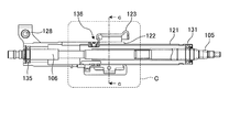
- FIG. 2 is a perspective view showing a steering column device of the steering device according to the first to fourth embodiments.
- FIG. 3 is a view showing a side surface of the steering column device according to the first to fourth embodiments.
- FIG. 4 is a view showing the front (rear side) of the steering column device according to the first to fourth embodiments.
- FIG. 5 is a view illustrating a side surface (partially cross-sectional view) of the steering column device according to the first embodiment.
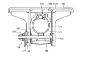
- FIG. 6 is a diagram showing a cross section along line aa in FIG.
- FIG. 7 is an enlarged view of part A in FIG.
- FIG. 8 is a view showing the bottom surface of FIG.
- FIG. 9 is a perspective view showing the fixing bracket according to the first embodiment.
- FIG. 10 is a perspective view showing the fixing bracket according to the first embodiment.
- FIG. 11 is a diagram illustrating a side surface (partially cross-sectional view) of the steering column device according to the second embodiment.
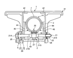
- FIG. 12 is a view showing a bb cross section of FIG.
- FIG. 13 is an enlarged view of part B of FIG.
- FIG. 14 is a diagram showing a bottom surface of FIG. 11 (a bottom view of the steering column device).
- FIG. 15 is a view similar to FIG. 13 showing a modification of the second embodiment.
- FIG. 16 is a diagram illustrating a side surface (partially cross-sectional view) of the steering column device of the third embodiment.
- FIG. 17 is a view showing a cc cross section of FIG.
- FIG. 18 is an enlarged view of part C in FIG.
- FIG. 19 is a view showing the bottom surface of FIG. 16 (bottom view of the steering column device).
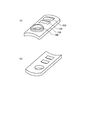
- FIG. 20 is a diagram illustrating the inner plate according to the third embodiment.
- FIG. 21 is a diagram illustrating an inner plate according to a modification of the third embodiment.
- FIG. 22 is a diagram illustrating an inner plate attachment method according to the third embodiment.
- FIG. 23 is a diagram illustrating an inner plate attachment method according to the third embodiment.
- FIG. 24 is an explanatory diagram for explaining an attachment state of the steering device according to the fifth embodiment.
- FIG. 25 is a side view schematically showing a steering column of the steering apparatus according to the fifth embodiment.
- FIG. 25 is a side view schematically showing a steering column of the steering apparatus according to the fifth embodiment.
- FIG. 26 is a sectional view taken along the line dd of FIG.
- FIG. 27 is a cross-sectional view schematically showing a cross section including the input shaft and the output shaft of FIG.
- FIG. 28 is an explanatory diagram for explaining a state in which the second fixing mechanism according to the fifth embodiment is fixed.
- FIG. 29 is an explanatory diagram for explaining a state in which the second fixing mechanism according to the fifth embodiment is unlocked.
- FIG. 30 is a plan view of the second fixing mechanism according to the fifth embodiment as viewed from the lower side in the tilt direction.
- FIG. 31 is an explanatory diagram for explaining a state of the second fixing mechanism according to the fifth embodiment when a primary collision occurs.
- FIG. 32 is an explanatory diagram for explaining a load at the time of a secondary collision that can be displaced after the primary collision of the steering column of the steering device according to the comparative example occurs.
- FIG. 33 is an explanatory diagram for explaining a load at the time of a secondary collision that can be displaced after a primary collision has occurred in the steering column of the steering apparatus according to the fifth embodiment.
- FIG. 34 is an explanatory diagram for explaining a state in which the second fixing mechanism according to the modification of the fifth embodiment is fixed.
- FIG. 35 is an explanatory diagram for explaining a state in which the second fixing mechanism according to the sixth embodiment is fixed.
- FIG. 36 is a plan view of the second fixing mechanism according to the sixth embodiment as viewed from the lower side in the tilt direction.
- FIG. 37 is an explanatory diagram for explaining a state of the second fixing mechanism according to the sixth embodiment when a primary collision occurs.
- Embodiments 1 to 4 relate to a steering device, specifically a steering column device.
- the present invention relates to a steering column of a steering apparatus, which can be tilted and telescopically operated and has an impact energy absorbing function.
- Patent Document 1 Japanese Patent Laid-Open No. 2007-69800
- a stroke mechanism constituted by an outer column and an inner column
- the left and right telescopic multi-plates are individually fixed, there is a possibility that the column will be damaged due to the left and right variations of the separation load.
- Patent Document 2 Japanese Patent Application Laid-Open No. 2009-29152 discloses a structure in which the fixed portion slides when the telescopic fixing member generates an impact load.
- the fixing member since the fixing member is housed in the groove, it is necessary to lengthen the groove in order to increase the stroke amount, and the column tends to be enlarged.
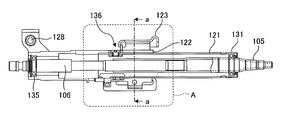
- a telescopic fitting structure consisting of an inner column and an outer column makes it possible to detach the inner column between the slits of the outer column with a T-shaped fixing bracket that fixes the friction plate (so-called telescopic multi-plate) of the fastening portion Fix it.
- a T-shaped fixing bracket that fixes the friction plate (so-called telescopic multi-plate) of the fastening portion Fix it.
- Holes are provided in the fixed bracket and inner column to insert and fix the pins.
- a multi-plate is arranged on the left and right, and the fixed surface at the center is separated (so-called T-shape).
- T-shape the fixed surface at the center is separated.
- the same fixing force is generated in the left and right fixing parts, and they are stretched when subjected to an impact load.
- the fixed surface at the center can be removed straight. Even if the load balance between the right and left fixed parts is lost, the slit of the outer column guides, so that it comes off relatively straight and strokes are possible. Also, the tightening rigidity of the column is improved.
- the shear pin when the shear pin is filled and filled using an injection method in which a resin is poured and hardened, play of the fixed portion can be suppressed. Even if it is fixed with resin pins, rivets, bolts, etc., it can be applied because the detachment load can be calculated from the material strength and the area of the sheared part.
- the second structure for solving the above problem is as follows. That is, in a telescopic fitting structure including an inner column and an outer column, the fixed side gear lock of the tightening fixing portion is fixed between the slits of the outer column so that the inner column can be detached. By detaching from the inner column, it is possible to detach at low load and absorb shock while preventing the column from falling off. Holes are provided in the fixed bracket and inner column to insert and fix the pins. When a secondary collision load is input to the steering shaft, it is transmitted to the inner column, the pin that fixes the fixed bracket shears, and the fixed surface of the fixed bracket and the inner column are displaced relative to each other, enabling a stroke greater than the telescopic stroke. To do.
- the shear pin when the shear pin is filled and filled using an injection method in which a resin is poured and hardened, play of the fixed portion can be suppressed. Even if it is fixed with resin pins, rivets, bolts, etc., it can be applied because the detachment load can be calculated from the material strength and the area of the sheared part.
- a flat plate that is not included in the gear of the known cam (for example, described in JP-A-2001-322552) and the fixed side gear lock. And the flat plate can be detached.
- the third structure for solving the above problem is as follows. That is, with a telescopic fitting structure of the inner column and outer column, a T-shaped fixing bracket that fixes the friction plate (multi-telescopic plate) of the fastening fixing portion is fixed between the slits of the outer column so that the inner column can be detached. . By detaching the fixed part from the inner column, it is possible to detach at low load and absorb shock while preventing the column from falling off. Holes are provided in the fixed bracket and inner column to insert and fix the pins.
- a method of arranging multiple plates on the left and right sides and detaching the central fixed surface is preferable.
- the same fixing force is generated in the left and right fixing parts, and they are stretched when subjected to an impact load.
- the fixed surface at the center can be removed straight. Even if the load balance between the right and left fixed parts is shifted, the slit of the outer column guides, so that it comes off relatively straight and stroke is possible. Also, the tightening rigidity of the column is improved.
- the shear pin uses an injection method in which a resin is poured and cured.
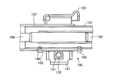
- the fixing bracket caulks and fixes the inner plate to the inner column from the inside, and temporarily closes the hole of the inner column through which the shear pin passes.
- the holes through which the shear pins of the fixed bracket pass are overlapped and positioned, and resin is injected from the holes on the fixed bracket side and cured to be fixed integrally. Since the separation load can be calculated from the area of the shearing portion, it can be applied to achieve stable separation.
- the inner plate is provided with a resin pool, and filling the resin can prevent the resin from dropping from the hole. Furthermore, when the resin is protruded and filled, the play of the fixed portion can be suppressed. Visual confirmation of the filling amount is also possible.
- FIGS. 1 to 4 schematically show the first to fourth embodiments. 5 to 10 specifically show the structure of the first embodiment.
- FIGS. 11 to 15 specifically show the structure of the second embodiment
- FIGS. 16 to 23 show the structure of the third embodiment.
- the axial direction DA indicates the axial direction of the steering shaft
- the front DF and the rear DB indicate the front and rear of the vehicle body when the steering device is attached to the vehicle body.
- the steering column device is a steering column device that supports a steering shaft, and the steering column includes an inner column and an outer column, and has a function of stroke in the axial direction so that telescopic adjustment and shock absorption are possible.
- the tilt adjustment is possible via a tilt bracket attached to the vehicle body, and the inner column is held by tightening the outer column with the tightening mechanism provided on the tilt bracket.
- the telescopic multi-plate which increases the surface is fixed to the bottom of the column and the fixed bracket provided between the slits of the outer column, and the hole on the side of the inner column matches the hole on the side of the fixed bracket
- Tsu inner column from bets is characterized in that it is supported detachably.
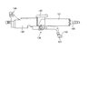
- the first embodiment is a steering column device 120 that supports a steering shaft including a male steering shaft 106 and a female steering shaft 105, and the steering column includes an inner column 121 and an outer column 122, and can be telescopically adjusted. It has a function to stroke in the axial direction so as to be able to absorb shocks, and can be adjusted for tilt via a tilt bracket 123 attached to the vehicle body.
- the inner column 121 is held and has a telescopic multi-plate 125 that increases the friction surface of the tightening mechanism 129.
- the telescopic multi-plate 125 is on the bottom side of the columns (121, 122) and the outer column. Between 122 slits The inner column 121 is detachably supported from the fixed bracket 124 by being fixed to the fixed bracket 124 provided and by inserting a shear pin with the hole of the inner column 121 and the hole of the fixed bracket 124 aligned. This is the steering column device 120.
- the steering column device is a steering column device that supports a steering shaft, and the steering column includes an inner column and an outer column, has a telescopic operation and a function capable of absorbing shock, and is relatively axial.
- Stroke is attached to the vehicle body so that the tilt can be adjusted via a tilt bracket attached to the vehicle body, and the tilt bracket has a tightening mechanism and holds the inner column by tightening the outer column.
- the outer column has a slit, and the inner column is held by a pressing bracket that presses the slit from the left and right directions by the action of a tightening mechanism, and is detachably attached to the inner column between the slits.
- a fixing plate is arranged to configure the tightening mechanism By rotation of the tilt lever that, by rotating the tilt lever center of the cam, pressing upward from below the cam to the fixing plate, and having a clamping mechanism for holding.
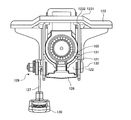
- the second embodiment is a steering column device 120 that supports a steering shaft composed of a male steering shaft 106 and a female steering shaft 105
- the steering column device 120 includes an inner column 121 and an outer column 122, and includes telescopic operation and impact. It has an absorbable function and moves in a relatively axial direction, and is attached to the vehicle body via a tilt bracket 123 attached to the vehicle body so that the tilt can be adjusted.
- the tilt bracket 123 includes a tightening mechanism 129.
- the inner column 121 is held by tightening the outer column 122.
- the outer column 122 has a slit, and the inner portion is pressed by a pressing bracket 1232 that presses the slit from the left and right directions by the action of the tightening mechanism 129.
- a tilt lever that constitutes a tightening mechanism 129 which includes a column 121, and a cam and gear mechanism 148 that functions as a fixing plate removably attached to the inner column 121 is disposed between the slits.
- a cam lock mechanism 133 which is a cam at the center of the tilt lever, is rotated to press and hold the cam portion formed on the center portion of the tilt bolt 153 from below to above the fixing plate.
- the steering column device 120 is characterized by having the following.
- the steering column device is a steering column device that supports a steering shaft, and the steering column includes an inner column and an outer column, and strokes in an axial direction so as to be capable of telescopic adjustment and shock absorption. It is equipped with a tilt bracket that can be attached to the vehicle body, and can be attached to the vehicle body so that the tilt can be adjusted.By tightening the tilt bracket, outer column, and telescopic multi-plate as a friction plate with a tightening mechanism, The inner column is held by the inner column.
- the outer column has a slit, and the clamping mechanism holds the inner column with a pressing bracket that presses the slit from the left and right.
- the fixed plate is disposed which, further fixing bracket for fixing the friction plate, characterized in that fixedly connected to the inner column by injection molding of resin.
- the third embodiment is a steering column device that supports a steering shaft.
- the steering column includes an inner column and an outer column, and has a telescopic adjustment function and a stroke in an axial direction so as to absorb shock, and is attached to a vehicle body. It is equipped with a tilt bracket and is attached to the vehicle body so that the tilt can be adjusted.
- a tilt bracket By tightening the tilt bracket, the outer column, and the telescopic multi-plate as a friction plate by a tightening mechanism, the inner fitting is fitted in the outer column. Holds the column.
- the outer column has a slit, and the tightening mechanism holds the inner column with a pressing bracket that presses the slit from the left and right.
- the inner column can be detached from the slit.
- the steering column device is characterized in that an inner plate 158 is disposed and a fixed bracket for fixing the friction plate is coupled and fixed to the inner column by shear pins 137 and 138 formed by resin injection molding. .
- Embodiment 4 is a steering device including the steering column device according to any one of Embodiments 1 to 3.
- the steering device of Embodiment 4 can be suitably used as a steering device for a vehicle.
- FIG. 24 is a configuration diagram of a steering device according to the fifth embodiment.
- the outline of the steering apparatus according to the fifth embodiment will be described with reference to FIG.
- the front of the vehicle body when the steering device 100 is attached to the vehicle body is simply referred to as the front
- the rear of the vehicle body when the steering device 100 is attached to the vehicle body is simply referred to as the rear.
- the front is the left side in the figure
- the rear is the right side in the figure.
- the steering device 100 is installed on the vehicle body VB, and includes a steering wheel 4, a steering shaft 15, a universal joint 9, a lower shaft 10, and a universal joint 11 in the order in which a force F given by an operator is transmitted. , And joined to the rack and pinion RP.
- the steering shaft 15 includes an input shaft 5 and an output shaft 8.
- the input shaft 5 has one end connected to the steering wheel 4 and the other end connected to the output shaft 8.
- the output shaft 8 has one end connected to the input shaft 5 and the other end connected to the universal joint 9 in the steering column.
- the input shaft 5 and the output shaft 8 are iron or the like.
- the lower shaft 10 has one end connected to the universal joint 9 and the other end connected to the universal joint 11.
- One end of the rack and pinion RP is connected to the universal joint 11.
- the steering device 100 includes a cylindrical inner column 3 that rotatably supports the input shaft 5 and a cylindrical outer column 7 into which at least a part of the inner column 3 is inserted inside. Is provided.
- the inner column 3 is disposed behind the outer column 7.
- the axial direction of the inner column 3 and the axial direction of the outer column 7 are simply simply referred to as axial directions.
- the steering device 100 includes a column bracket 1 that is fixed to the vehicle body side member 13 and supports the outer column 7.
- the column bracket 1 is fixed to the vehicle body side member 13 with a bolt or the like so that it cannot be detached.
- the outer column 7 has a pivot bracket 12 provided at the front end.
- the pivot bracket 12 is supported by the vehicle body VB so as to be rotatable about the rotation axis PV.
- the rotation axis PV is, for example, parallel to the horizontal direction.
- the outer column 7 is supported so as to be swingable in the vertical direction. The operator can adjust the position in the tilt direction by rotating the operation lever 6 and then swinging the steering column 14 in the vertical direction via the steering wheel 4. Further, the operator can adjust the telescopic position by rotating the operation lever 6 and then moving the inner column 3 via the steering wheel 4.
- the lower shaft 10 is disposed in the vicinity of the bulkhead BH having a partition wall that separates the vehicle compartment from the engine compartment.
- the pinion of the rack and pinion RP meshes with a rack shaft (not shown).
- the steering torque (including auxiliary steering torque) output via the output shaft 8 is transmitted to the lower shaft 10 via the universal joint 9 and further transmitted to the pinion via the universal joint 11.
- the steering force transmitted to the pinion is transmitted to a tie rod (not shown) via a steering gear (not shown) and a rack (not shown) to steer a steered wheel (not shown).
- the outer column 7 is supported by the vehicle body VB via the vehicle body side member 13, and when force is transmitted from the steering wheel 4 to the steering column 14 at the time of the secondary collision, the inner column 3 is inserted into the outer column 7 while the outer column 7 is fixed to the vehicle body VB and is accommodated in the outer column 7, and the impact received by the operator from the steering wheel 4 can be reduced.
- the weight of the operator is light, it is better to lower the set value of the separation load at which the inner column 3 of the steering column 14 moves to the front of the vehicle body.
- the frictional force generated between the column 7 is lowered.
- the steering device 100 according to the fifth embodiment includes the second fixing mechanism 2 in addition to the pressure of the first fixing mechanism 20 sandwiched by the column bracket 1.
- FIG. 25 is a side view schematically showing a steering column of the steering apparatus according to the fifth embodiment.
- FIG. 26 is a sectional view taken along the line dd of FIG.
- FIG. 27 is a cross-sectional view schematically showing a cross section including the input shaft and the output shaft of FIG.
- FIG. 28 is an explanatory diagram for explaining a state in which the second fixing mechanism according to the fifth embodiment is fixed.
- FIG. 29 is an explanatory diagram for explaining a state in which the second fixing mechanism according to the fifth embodiment is unlocked.
- FIG. 30 is a plan view of the second fixing mechanism according to the fifth embodiment as viewed from the lower side in the tilt direction.
- FIG. 30 is an arrow view in the ee direction in FIG.
- the second fixing mechanism 2 of the steering device 100 will be described with reference to FIGS.
- the input shaft 5 and the output shaft 8 are not shown.
- the inner column 3 includes a bearing 3R that rotatably supports the input shaft 5.
- the outer column 7 includes a bearing 7R that rotatably supports the output shaft 8.
- the inner column 3 is inserted so that at least a part of the outer peripheral surface thereof faces the inner surface of the outer column 7, and a power transmission mechanism SE such as serration or spline is formed at the opposite portion, and the rotation of the input shaft 5 is performed. Can be transmitted to the rotation of the output shaft 8.
- the column bracket 1 has a mounting plate portion 41 fixed to the vehicle body side member 13 shown in FIG. 24 and a mounting plate portion 41 so as to sandwich the outer column 7 therebetween. And a pressing bracket 42 fixed to the head.
- the pressing brackets 42 are disposed on both sides of the outer column 7, and the outer column 7 can be tightened via the distance bracket 43.
- the pressing bracket 42 is provided with a tilt adjusting hole which is a long hole, and the tilt bolt 21 interlocking with the rotation of the operation lever 6 can be passed therethrough.
- the distance bracket 43 includes a positioning portion 44 having a semicircular recess for positioning the outer column 7, and is fixed by a welding process or the like at a fixed position 45 in contact with the outer column 7.
- the outer column 7 and the distance bracket 43 may be integrally formed by aluminum die casting.
- the first fixing mechanism 20 is a cam mechanism, and is slidably attached to the first rotating cam portion 23 that is attached to the operation lever 6 and rotates integrally therewith, and the tilt adjustment hole of the column bracket 1. And a first fixed cam portion 24 that is not relatively rotatable so as not to interlock with the rotation of the first fixed cam portion 24.
- the first rotating cam portion 23 and the first fixed cam portion 24 are uneven in the circumferential direction. When the first rotating cam portion 23 and the first fixed cam portion 24 are rotated relative to each other, the first rotation cam portion 23 and the first fixed cam portion 24 are rotated according to the rotation position of the first rotation cam portion 23. The distance between the cam portion 23 and the first fixed cam portion 24 is changed.
- the tilt bolt 21 includes a tilt bolt head portion 21A, a bolt body 21B, a second rotating cam portion 21G, and a screw portion 21D.
- the tilt bolt 21 passes through the operation lever 6, the first rotating cam portion 23, the first fixed cam portion 24, the pressing bracket 42, the distance bracket 43, the pressing bracket 42, and the thrust bearing 26, and a screw portion 21 ⁇ / b> D is formed on the caulking nut 22. It is concluded.
- the spin stopper 25 fixed to the tilt bolt head portion 21A sandwiches the first fixed cam portion 24 and the operation lever 6, and interlocks the rotation of the operation lever 6 with the rotation of the tilt bolt 21 and the first rotation cam portion 23. I am letting.
- the thrust bearing 26 is supported so as to be movable in the axial direction of the tilt bolt 21 because the distance between the first rotating cam portion 23 and the first fixed cam portion 24 changes according to the rotational position of the first rotating cam portion 23. To do.
- the first rotating cam portion 23 and the first fixed cam portion 24 changes according to the rotational position of the first rotating cam portion 23, the first rotating cam portion 23 and the first fixed cam portion 24 When the distance becomes smaller, the pressure sandwiching the pressing brackets 42 becomes smaller. For this reason, according to the rotation of the operation lever 6, the tightening force acting between the pressing brackets 42 is loosened, and the frictional force between the pressing brackets 42 and the outer column 7 is eliminated or reduced. As a result, the operator can swing the steering column 14 in the vertical direction along the longitudinal direction of the tilt adjustment hole via the steering wheel 4 by rotating the operation lever 6. Then, the operator can adjust the tilt position of the outer column 7.
- the tilt position of the steering column 14 can be fixed by rotating the operation lever 6. Further, by rotating the operation lever 6, the pressure sandwiched between the column brackets 1 can be increased, the frictional force generated between the inner column 3 and the outer column 7 can be increased, and the telescopic position can be fixed.
- the second fixing mechanism 2 is a cam mechanism, and is provided on the outer periphery of the second rotating cam portion 21 ⁇ / b> G of the tilt bolt 21 that rotates integrally with the operation lever 6, the gear lock 27, and the inner column 3. And a fixed plate portion 28 which is a pressed portion.
- the gear lock 27 is a lock member and includes a tooth portion 27G.
- the fixed plate portion 28 is a gear lock member and includes a tooth portion 28G on the surface.
- the tooth portion 28G has an uneven shape that matches the uneven shape and pitch of the tooth portion 27G.
- the gear lock 27 is attached to the second rotating cam portion 21G so that the tooth portion 27G faces the tooth portion 28G.
- the second rotating cam portion 21G is a so-called eccentric clamp that is eccentric with respect to the axis of the bolt main body 21B.
- the gear lock 27 shown in FIG. 28 is pressed against the fixed plate portion 28 and fixed, and the gear lock 27 shown in FIG. 29 is fixed. It is possible to select a state in which the fixing is released from the plate portion 28.
- the gear lock 27 is urged toward the fixed plate portion 28 by the axial force generated in the second rotating cam portion 21G, and the tooth portion 27G meshes with the tooth portion 28G. In this case, the distance between the first rotating cam portion 23 and the first fixed cam portion 24 is reduced. Therefore, the second fixing mechanism 2 is urged in the tilt direction with respect to the column bracket 1 and is securely fixed in the telescopic direction with respect to the fixing plate portion 28 side.
- the fixed plate portion 28 is fixed to the inner column 3 at the position of the slit 7S of the outer column 7. For this reason, the width ⁇ w of the fixed plate portion 28 is smaller than the width ⁇ S of the slit 7S. Thereby, the fixed plate portion 28 does not serve as a tightening resistance acting between the pressing brackets 42.
- the fixed plate portion 28 is fixed to the inner column 3 by a detachment mechanism 30.
- the release mechanism 30 includes a first hole 28 h on the fixed plate portion 28 side, a second hole 3 h on the inner column 3 side, and a shear pin 31.
- the shear pin 31 is a mechanical fuse for receiving a shearing force and breaking when a secondary collision occurs.
- the separation load at which the shear pin 31 breaks depends on the material of the shear pin 31 and the cross-sectional area of the shear surface.
- the share pin 31 is in a position straddling the first hole 28h on the fixed plate portion 28 side and the second hole 3h on the inner column 3 side in a state before separation. As shown in FIG.
- the shear pin 31 is provided at one end of the cylindrical shear pin body, the shear pin body, the shear pin head 32 having a diameter larger than the diameter of the shear pin body, and the other end of the shear pin body.
- a hook portion 34 is provided at the edge of the second hole 3h.
- a hollow and bottomed hollow portion 33 is opened in the shear pin main body, and an elastic force to the outside is biased to the hook portion 34.
- the shear pin 31 has a pin shape, but is embedded by using resin injection or the like for pouring resin into the first hole 28h on the fixed plate portion 28 side and the second hole 3h on the inner column 3 side to cure. It may be a shared pin.
- FIG. 31 is an explanatory diagram for explaining a state of the second fixing mechanism according to the fifth embodiment when a primary collision occurs.
- FIG. 32 is an explanatory diagram for explaining a load at the time of a secondary collision that can be displaced after the steering column of the steering device according to the comparative example has a primary collision.
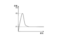
- FIG. 33 is an explanatory diagram for explaining a load at the time of a secondary collision that can be displaced after a primary collision has occurred in the steering column of the steering apparatus according to the fifth embodiment.
- the horizontal axis represents the amount of forward displacement of the inner column 3
- the vertical axis represents the load required to move the inner column 3 forward.
- the comparative example is an example in which the outer column is attached to the vehicle body via the capsule as in the technique described in Patent Document 1.
- the outer column is arranged on the rear side of the inner column, and when an excessive load is applied to the outer column, the rod contacts the end of the telescopic adjustment hole provided integrally with the outer column, and the bracket The load is transmitted to the capsule via the.
- a force F5 shown in FIG. 32 indicates the allowable shear force of the capsule.
- the outer column is supported in the axial direction by a frictional force generated between the outer column and the inner column by tightening the bracket.
- a force F4 shown in FIG. 32 indicates the friction force supporting the outer column.
- the force F4 is smaller than the force F5.
- the force F4 needs to be maintained at a predetermined value or more.
- the inner column 3 is caused by the first frictional force generated between the inner column 3 and the outer column 7 by the tightening of the column bracket 1 by the first fixing mechanism 20 and the second frictional force by the second fixing mechanism 2.
- the outer column 7 is fixed and supported in the axial direction.
- a force F1 shown in FIG. 33 indicates the first friction force
- a force F3 indicates the sum of the first friction force and the second friction force.
- a force F2 shown in FIG. 33 indicates an allowable shear force of the shear pin 31 of the detachment mechanism 30. The force F2 is smaller than the force F3 and larger than the force F1.
- Embodiment 5 when a load of force F2 or more is applied to the inner column 3, the shear pin 31 is cut and the inner column 3 is detached from the column bracket 1 (fixed plate portion 28). Thereby, since the connection of the second fixing mechanism 2 is released, the second frictional force described above does not act on the inner column 3. For this reason, after the shear pin 31 of the detachment mechanism 30 is cut, the inner column 3 moves in the axial direction while absorbing the impact by the first frictional force described above. When the first frictional force is set to a small value, the steering device 100 according to Embodiment 5 smoothes the movement of the inner column 3 and reduces the impact of the secondary collision that is given to the operator.
- the steering device 100 adjusts the added value of the first frictional force setting value and the second frictional force setting value, so that the inner column 3 is caused by a load applied during normal use. The movement can be suppressed and the impact of the secondary collision given to the operator can be reduced.
- the steering device 100 includes the cylindrical inner column 3, the cylindrical outer column 7, the column bracket 1, the fixing plate portion 28, the first fixing mechanism 20, A second fixing mechanism 2 and a release mechanism 30 are provided.
- the inner column 3 rotatably supports an input shaft 5 connected to the steering wheel 4.
- the outer column 7 is a cylindrical member into which at least a part of the inner column 3 is inserted, and has a slit 7S in which one end on the insertion side of the inner column 3 is cut out.
- the column bracket 1 is fixed to the vehicle body side member 13, and the outer column 7 is fastened by a pressing bracket 42 that sandwiches the outer column 7.
- the fixed plate portion 28 is disposed at least partially inside the slit 7 ⁇ / b> S of the outer column 7 and is provided on the outer periphery of the inner column 3.
- the first fixing mechanism 20 tightens the outer column 7 with the pressing bracket 42 according to the rotation of the operation lever 6, and increases the first frictional force generated between the inner column 3 and the outer column 7.
- the second fixing mechanism 2 biases the gear lock 27 that is a lock member in the tilt direction with respect to the fixed plate portion 28 according to the rotation of the operation lever 6.
- the inner column 3 is pressed by the pressing bracket.
- the relative position with respect to 42 is changed so that it can be detached.
- the outer column 7 is supported on the vehicle body VB via the vehicle body side member 13, and when force is transmitted from the steering wheel 4 to the steering column 14 at the time of the secondary collision, the inner column 3 Is inserted into the outer column 7 and accommodated in the outer column 7. In this case, the outer column 7 remains fixed to the vehicle body VB. Even if the inner column 3 is inserted into the outer column 7 due to a malfunction, the steering column does not fall. Even if the pressure sandwiched between the column brackets 1 is reduced and the frictional force generated between the inner column 3 and the outer column 7 is reduced, the second fixing mechanism 2 attaches the gear lock 27 to the fixing plate portion 28 in the tilt direction. Therefore, the possibility of exceeding the separation load even when the load is other than the secondary collision is reduced. For this reason, in order to relieve the impact of the secondary collision on the operator with a light weight, the set value of the separation load at which the steering wheel 4 (inner column 3) moves forward of the vehicle body can be lowered.
- the fixed plate portion 28 is at least partially disposed inside the slit 7S of the outer column 7, and is fixed to the inner column 3 so as to be detachable. For this reason, when the vehicle body VB collides (primary collision), the inner column 3 is detached from the column bracket 1 (fixing plate portion 28), and the connection of the second fixing mechanism 2 is released. Thereby, the second frictional force described above does not act on the inner column 3.
- the steering device 100 can mitigate the impact (secondary collision) of a light operator.
- the separation mechanism 30 includes a first hole 28h in the fixed plate portion 28 and a shear pin 31 provided so as to straddle the second hole 3h and the first hole 28h opened in the inner column 3.
- the shear pin 31 receives a shearing force when the steering column 14 is pushed forward of the vehicle body.
- the shear pin 31 is broken, the connection between the fixing plate portion 28 and the inner column 3 is released, and the connection of the second fixing mechanism 2 is released. For this reason, the force by which the second fixing mechanism 2 urges the gear lock 27 in the tilt direction with respect to the fixed plate portion 28 is not transmitted, and the above-described second frictional force does not act.
- the tilt bolt 21 passes through the pressing bracket 42 and rotates in conjunction with the operation lever 6.
- the second rotating cam portion 21G is provided at a position facing the slit 7S of the outer column 7 and rotates in conjunction with the tilt bolt 21.
- the position of the gear lock 27 which is a lock member changes in the tilt direction relative to the fixed plate portion 28 according to the rotation of the second rotating cam portion 21G. For this reason, the operator can release the fixation of the second fixing mechanism 2 and adjust the tilt position and the telescopic position only by operating the operation lever 6. In addition, the operator can fix the tilt position and the telescopic position by fixing the second fixing mechanism 2 only by operating the operation lever 6.
- the gear lock 27, which is a lock member, includes a tooth portion 27G at a contact portion with the fixed plate portion 28.
- the fixed plate portion 28 includes a tooth portion 28G on the surface. Thereby, the 2nd fixing mechanism 2 is reliably fixed to the telescopic direction with respect to the fixing plate part 28 side.
- the outer column 7 is positioned on the front side of the vehicle body, includes a pivot bracket 12, and the detached inner column 3 can be inserted. With this structure, even if the inner column 3 is inserted into the outer column 7 due to a malfunction, the steering column 14 does not fall.
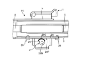
- FIG. 34 is an explanatory diagram for explaining a state in which the second fixing mechanism according to the modification of the fifth embodiment is fixed.
- symbol is attached
- the second fixing mechanism 2 is a cam mechanism, and includes a second rotating cam portion 21G of the tilt bolt 21 that rotates integrally with the operation lever 6, an eccentric cam 29, and the like. And a fixed plate portion 28 attached to the inner column 3.
- the eccentric cam 29 is a lock member and includes a sliding contact portion 29G.
- the eccentric cam 29 is fixed to the second rotating cam portion 21G by press fitting or the like, and rotates in conjunction with the rotation of the second rotating cam portion 21G.
- the sliding contact portion 29G has anti-slip processing such as knurl processing, gear processing, and uneven shape on the surface.
- the fixed plate portion 28 is a flat plate member having a smooth surface 28P, and the surface is flat.
- the fixed plate portion 28 may be knurled, geared, uneven or the like on the surface.
- the second rotating cam portion 21G may have the same diameter with respect to the axis of the bolt main body 21B or may be a so-called clamp bolt that is eccentric.
- the sliding contact portion 29G of the eccentric cam 29 shown in FIG. 34 is pressed against the fixed plate portion 28, and the eccentric cam. It is possible to select a state in which the 29 sliding contact portions 29G are separated from the fixed plate portion 28 and the fixation is released.
- the sliding contact portion 29G is urged and fixed to the fixed plate portion 28 side. In this case, the distance between the first rotating cam portion 23 and the first fixed cam portion 24 is reduced. Therefore, the second fixing mechanism 2 is urged in the tilt direction with respect to the column bracket 1 and is securely fixed in the telescopic direction with respect to the fixing plate portion 28 side.
- the eccentric cam 29 that is a lock member includes a sliding contact portion 29G at a contact portion with the fixed plate portion 28.
- the second fixing mechanism 2 is urged in the tilt direction with respect to the column bracket 1 and is securely fixed in the telescopic direction with respect to the fixing plate portion 28 side.
- the second fixing mechanism 2 biases the eccentric cam 29 that is a lock member in the tilt direction with respect to the fixed plate portion 28 according to the rotation of the operation lever 6. For this reason, even if the fixed plate portion 28 is a flat plate member having the smooth surface 28P, the eccentric cam 29 is reliably fixed in the telescopic direction to the fixed plate portion 28 side.
- FIG. 35 is an explanatory diagram for explaining a state in which the second fixing mechanism according to the sixth embodiment is fixed.
- FIG. 36 is a plan view of the second fixing mechanism according to the sixth embodiment as viewed from the lower side in the tilt direction.
- FIG. 37 is an explanatory diagram for explaining a state of the second fixing mechanism according to the sixth embodiment when a primary collision occurs.
- symbol is attached
- the steering device according to the sixth embodiment includes a first lock member 27B and a second lock member 27A in which the lock member is divided in the tilt direction.
- the detaching mechanism 30 fixes the second lock member 27A so as to be detachable with respect to the second lock member 27A that is in contact with the fixed plate portion 28 that is the pressed portion.
- the steering apparatus according to the sixth embodiment will be described in more detail with reference to FIGS. 35 to 37.
- the gear lock 27 is a lock member, and includes a first lock member 27B and a second lock member 27A.
- the first lock member 27 ⁇ / b> B includes a tooth portion 27 ⁇ / b> G that comes into contact with the fixed plate portion 28.
- the fixed plate portion 28 is a pressed portion including a tooth portion 28G on the surface.
- the tooth portion 28G has an uneven shape that matches the uneven shape and pitch of the tooth portion 27G.
- the gear lock 27 is attached to the second rotating cam portion 21G so that the tooth portion 27G faces the tooth portion 28G.
- the first lock member 27B and the second lock member 27A are fixed by the release mechanism 30.
- the opposing surfaces of the first lock member 27B and the second lock member 27A are preferably smooth flat surfaces.
- the separation mechanism 30 includes a first hole 27Bh of the first lock member 27B, a second hole 27Ah of the second lock member 27A, and a shear pin 31.
- the shear pin 31 is a mechanical fuse for receiving a shearing force and breaking when a secondary collision occurs. The separation load at which the shear pin 31 breaks depends on the material of the shear pin 31 and the cross-sectional area of the shear surface.
- the share pin 31 is in a position straddling the first hole 27Bh of the first lock member 27B and the second hole 27Ah of the second lock member 27A in a state before detachment.
- the shear pin 31 is provided at a cylindrical shear pin main body, one end of the shear pin main body, a shear pin head 32 having a diameter larger than the diameter of the shear pin main body, and provided at the other end of the shear pin main body, A hook portion 34 is provided at the edge of the second hole 27Ah.
- a hollow and bottomed hollow portion 33 is opened in the shear pin main body, and an elastic force to the outside is biased to the hook portion 34.
- the shear pin 31 has a pin shape, but resin injection or the like is performed by pouring resin into the first hole 27Bh of the first lock member 27B and the second hole 27Ah of the second lock member 27A. It may be an embedded shear pin.
- the second rotating cam portion 21G is a so-called eccentric clamp that is eccentric with respect to the axis of the bolt main body 21B.
- the first lock member 27B is pressed against the fixed plate portion 28 via the second lock member 27A and fixed, and the second lock
- the state in which the first lock member 27B is separated from the fixed plate portion 28 via the member 27A and the fixation is released can be selected.
- the second locking member 27A is biased toward the fixed plate portion 28 by the axial force generated in the second rotating cam portion 21G, and the tooth portion 27G of the first locking member 27B together with the second locking member 27A. It meshes with the tooth portion 28G.
- the second fixing mechanism 2 is urged in the tilt direction with respect to the column bracket 1 and is securely fixed in the telescopic direction with respect to the fixing plate portion 28 side.
- the first lock member 27B is separated from the fixed plate portion 28 via the second lock member 27A, and the fixing is released. Then, the pressing force applied to the fixed plate portion 28 provided by the gear lock 27 is released. In this case, the distance between the first rotating cam portion 23 and the first fixed cam portion 24 is increased. Thereby, the operator can adjust the tilt position and the telescopic position.
- the fixed plate portion 28 is fixed to the inner column 3 at the position of the slit 7S of the outer column 7.
- the inner column 3 and the fixing plate portion 28 may be fixed by bolts or the like, but is preferably fixed by welding at a welding position 28w shown in FIG.
- the width ⁇ w of the fixed plate portion 28 is smaller than the width ⁇ S of the slit 7S.
- the pressed portion of the sixth embodiment is the fixed plate portion 28, but is not limited thereto, and the pressed portion may directly form the shape of the tooth portion 28 ⁇ / b> G on the outer peripheral surface of the inner column 3.
- the steering device 100 includes the cylindrical inner column 3, the cylindrical outer column 7, the column bracket 1, the fixing plate portion 28, the first fixing mechanism 20, A second fixing mechanism 2 and a release mechanism 30 are provided.
- the inner column 3 rotatably supports an input shaft 5 connected to the steering wheel 4.
- the outer column 7 is a cylindrical member into which at least a part of the inner column 3 is inserted, and has a slit 7S in which one end on the insertion side of the inner column 3 is cut out.
- the column bracket 1 is fixed to the vehicle body side member 13, and the outer column 7 is fastened by a pressing bracket 42 that sandwiches the outer column 7.
- the fixed plate portion 28 is disposed at least partially inside the slit 7 ⁇ / b> S of the outer column 7 and is provided on the outer periphery of the inner column 3.
- the first fixing mechanism 20 tightens the outer column 7 with the pressing bracket 42 according to the rotation of the operation lever 6, and increases the first frictional force generated between the inner column 3 and the outer column 7.
- the second fixing mechanism 2 biases the gear lock 27 that is a lock member in the tilt direction with respect to the fixed plate portion 28 according to the rotation of the operation lever 6.
- the detachment mechanism 30 contacts the fixing plate portion 28.
- the outer column 7 is supported on the vehicle body VB via the vehicle body side member 13, and when force is transmitted from the steering wheel 4 to the steering column 14 at the time of the secondary collision, the inner column 3 Is inserted into the outer column 7 and accommodated in the outer column 7. In this case, the outer column 7 remains fixed to the vehicle body VB. Even if the inner column 3 is inserted into the outer column 7 due to a malfunction, the steering column 14 does not fall. Even if the pressure sandwiched between the column brackets 1 is reduced and the frictional force generated between the inner column 3 and the outer column 7 is reduced, the second fixing mechanism 2 attaches the gear lock 27 to the fixing plate portion 28 in the tilt direction.
- the set value of the separation load at which the steering wheel 4 (inner column 3) moves forward of the vehicle body can be lowered.
- the steering device 100 can mitigate the impact (secondary collision) of a light operator.
- the steering device according to the fifth and sixth embodiments described above can also be applied to a steering device including an electric motor.
Abstract
Description
実施形態1~4は、ステアリング装置、具体的にはステアリングコラム装置に関する。特に、ステアリング装置の操向コラムに関し、チルト及びテレスコピック動作が可能であり、衝撃エネルギ吸収機能を有するものに関する。 (
図24は、実施形態5に係るステアリング装置の構成図である。図24を用いて、実施形態5に係るステアリング装置の概要を説明する。また、以下の説明において、ステアリング装置100を車体に取り付けた場合の車体の前方は、単に前方と記載され、ステアリング装置100を車体に取り付けた場合の車体の後方は、単に後方と記載される。図24において、前方は、図中の左側であり、後方は、図中の右側である。 (Embodiment 5)
FIG. 24 is a configuration diagram of a steering device according to the fifth embodiment. The outline of the steering apparatus according to the fifth embodiment will be described with reference to FIG. In the following description, the front of the vehicle body when the
図34は、実施形態5の変形例に係る第2固定機構が固定している状態を説明するための説明図である。なお、上述したものと同じ構成には同一の符号を付して重複する説明は省略する。 (Modification of Embodiment 5)
FIG. 34 is an explanatory diagram for explaining a state in which the second fixing mechanism according to the modification of the fifth embodiment is fixed. In addition, the same code | symbol is attached | subjected to the same structure as what was mentioned above, and the overlapping description is abbreviate | omitted.
図35は、実施形態6に係る第2固定機構が固定している状態を説明するための説明図である。図36は、実施形態6に係る第2固定機構をチルト方向下側から見た平面図である。図37は、1次衝突が生じた場合における、実施形態6に係る第2固定機構の状態を説明するための説明図である。なお、上述した実施形態5と同じ構成には同一の符号を付して重複する説明は省略する。実施形態5のステアリング装置と異なり、実施形態6のステアリング装置は、ロック部材が、チルト方向に分かれた第1ロック部材27Bと第2ロック部材27Aとを含む。そして、離脱機構30は、被押圧部である固定板部28に当接する第2ロック部材27Aに対して、第2ロック部材27Aを離脱可能に固定する。以下、図35から図37を用いて、実施形態6のステアリング装置についてより詳細に説明する。 (Embodiment 6)
FIG. 35 is an explanatory diagram for explaining a state in which the second fixing mechanism according to the sixth embodiment is fixed. FIG. 36 is a plan view of the second fixing mechanism according to the sixth embodiment as viewed from the lower side in the tilt direction. FIG. 37 is an explanatory diagram for explaining a state of the second fixing mechanism according to the sixth embodiment when a primary collision occurs. In addition, the same code | symbol is attached | subjected to the same structure as
2 第2固定機構
3 インナーコラム
3h 第2孔
4 ステアリングホイール
5 入力軸
6 操作レバー
7 アウターコラム
7S スリット
8 出力軸
9 ユニバーサルジョイント
10 ロアシャフト
11 ユニバーサルジョイント
12 ピボットブラケット
13 車体側部材
14 ステアリングコラム
15 ステアリングシャフト
20 第1固定機構
21 チルトボルト
21A チルトボルト頭部
21B ボルト本体
21D ねじ部
21G 第2回転カム部
22 かしめナット
23 第1回転カム部
24 第1固定カム部
25 スピンストッパー
26 スラストベアリング
27 ギアロック
27A 第2ロック部材
27B 第1ロック部材
27G 歯部
28 固定板部
28h 第1孔
28G 歯部
29 偏芯カム
29G 摺接部
30 離脱機構
31 シェアピン
32 シェアピン頭部
33 中空部
34 フック部
41 取付板部
42 押圧ブラケット
43 ディスタンスブラケット
44 位置決め部
45 固定位置
100 ステアリング装置
101 操向ハンドル
102 ラックハウジング
103 ピニオン
104 タイロッド
105 雌ステアリング軸
106 雄ステアリング軸
107 十字継ぎ手
108 中間軸
109 十字継ぎ手
110 ステアリング装置
120 ステアリングコラム装置
121 インナーコラム
122 アウターコラム
123 チルトブラケット
1231 車体取付側ブラケット
1232 押圧ブラケット
124 固定ブラケット
125 テレスコ多板
126 テレスコ多板
127 チルトレバー
128 チルトボルト用孔
129 締付機構
130 操作部
131 転がり軸受
132 チルトボルト
133 カムロック機構
134 ナット
135 転がり軸受
136 抜け止め機構
137 せん断ピン
138 せん断ピン
139 インナーコラム接触面
140 せん断ピン用孔
141 せん断ピン用孔
142 固定部
143 固定部
144 横梁部
145 柱部
146 取付け部
147 ディスタンスブラケット
148 カム及びギヤ機構
149 せん断ピン
150 せん断ピン
151 可動側ギヤロック
152 固定側ギヤロック
153 チルトボルト中央部
154 カム機構
155 偏芯カム
156 押圧ブロック
157 押圧ブロック
158 インナープレート
159 凹部
160 嵌合突起部
161 嵌合孔部
162 射出口
RP ラックアンドピニオン
PV 回転軸
SE 動力伝達機構
VB 車体 DESCRIPTION OF SYMBOLS 1 Column bracket 2 2nd fixing mechanism 3 Inner column 3h 2nd hole 4 Steering wheel 5 Input shaft 6 Operation lever 7 Outer column 7S Slit 8 Output shaft 9 Universal joint 10 Lower shaft 11 Universal joint 12 Pivot bracket 13 Car body side member 14 Steering Column 15 Steering shaft 20 First fixing mechanism 21 Tilt bolt 21A Tilt bolt head 21B Bolt body 21D Screw portion 21G Second rotating cam portion 22 Caulking nut 23 First rotating cam portion 24 First fixed cam portion 25 Spin stopper 26 Thrust bearing 27 Gear lock 27A Second lock member 27B First lock member 27G Tooth part 28 Fixing plate part 28h First hole 28G Tooth part 29 Eccentric cam 29G Sliding contact part 30 Release mechanism 31 Share pin 32 Share pin Head portion 33 Hollow portion 34 Hook portion 41 Mounting plate portion 42 Press bracket 43 Distance bracket 44 Positioning portion 45 Fixed position 100 Steering device 101 Steering handle 102 Rack housing 103 Pinion 104 Tie rod 105 Female steering shaft 106 Male steering shaft 107 Cross joint 108 Intermediate shaft 109 Cross joint 110 Steering device 120 Steering column device 121 Inner column 122 Outer column 123 Tilt bracket 1231 Car body mounting side bracket 1232 Press bracket 124 Fixing bracket 125 Telescopic multi-plate 126 Telescopic multi-plate 127 Tilt lever 128 Tilt bolt hole 129 Tightening mechanism 130 Operation unit 131 Rolling bearing 132 Tilt bolt 133 Cam lock mechanism 134 Nut 1 5 Rolling bearing 136 Retaining mechanism 137 Shear pin 138 Shear pin 139 Inner column contact surface 140 Shear pin hole 141 Shear pin hole 142 Fixed portion 143 Fixed portion 144 Horizontal beam portion 145 Column portion 146 Mounting portion 147 Distance bracket 148 Cam and gear Mechanism 149 Shear pin 150 Shear pin 151 Movable side gear lock 152 Fixed side gear lock 153 Tilt bolt central part 154 Cam mechanism 155 Eccentric cam 156 Press block 157 Press block 158 Inner plate 159 Recess 160 Fit protrusion 161 Fit hole 162 Shooting Exit RP Rack and pinion PV Rotating shaft SE Power transmission mechanism VB Car body
Claims (12)
- ステアリングホイールに連結される入力軸を回転可能に支持する、筒状のインナーコラムと、
前記インナーコラムの少なくとも一部が内側に挿入される筒状部材であって、前記インナーコラムの挿入側の一端を切り欠いたスリットを有するアウターコラムと、
車体側部材に固定され、前記アウターコラムを挟む押圧ブラケットで前記アウターコラムを締め付けるコラムブラケットと、
前記インナーコラムの外周に備えられる被押圧部と、
操作レバーの回転に応じて、前記アウターコラムを締め付ける第1固定機構と、
前記操作レバーの回転に応じて、前記被押圧部に対してチルト方向にロック部材を付勢する第2固定機構と、
前記第1固定機構が前記アウターコラムを締め付け、かつ前記第2固定機構が前記被押圧部に対してチルト方向にロック部材を付勢する状態において、前記インナーコラムが前記押圧ブラケットとの相対位置を変えて離脱可能にする離脱機構と、
を備えることを特徴とするステアリング装置。 A cylindrical inner column that rotatably supports an input shaft connected to the steering wheel;
An outer column having a slit formed by cutting out one end of the inner column on the insertion side, at least a part of the inner column being inserted inside;
A column bracket fixed to the vehicle body side member and tightening the outer column with a pressing bracket sandwiching the outer column;
A pressed portion provided on the outer periphery of the inner column;
A first fixing mechanism for tightening the outer column in response to rotation of the operation lever;
A second fixing mechanism for urging the lock member in a tilt direction with respect to the pressed portion in response to rotation of the operation lever;
In a state where the first fixing mechanism tightens the outer column and the second fixing mechanism urges the lock member in the tilt direction with respect to the pressed portion, the inner column moves relative to the pressing bracket. A release mechanism that can be changed and released,
A steering apparatus comprising: - 前記被押圧部は、前記アウターコラムのスリットの内部に少なくとも一部が配置され、前記インナーコラムと離脱可能に固定された固定板部である、請求項1に記載のステアリング装置。 The steering device according to claim 1, wherein the pressed portion is a fixed plate portion that is at least partially disposed inside a slit of the outer column and is detachably fixed to the inner column.
- 前記離脱機構は、前記固定板部の第1孔と、前記インナーコラムの第2孔と、前記第1孔と前記第2孔とに跨るように設けられたシェアピンとを備え、前記インナーコラムと前記固定板部とを離脱可能に固定する、請求項2に記載のステアリング装置。 The detachment mechanism includes a first hole of the fixed plate portion, a second hole of the inner column, and a shear pin provided to straddle the first hole and the second hole, and the inner column, The steering device according to claim 2, wherein the fixing plate portion is detachably fixed.
- 前記押圧ブラケットを貫通し、前記操作レバーに連動するチルトボルトを備え、
前記第2固定機構は、前記アウターコラムのスリットに対向する位置に設けられ、前記チルトボルトと連動して回転する回転カム部を備える、請求項1から3のいずれか1項に記載のステアリング装置。 A tilt bolt penetrating the pressing bracket and interlocking with the operation lever;
The steering apparatus according to any one of claims 1 to 3, wherein the second fixing mechanism includes a rotating cam portion that is provided at a position facing the slit of the outer column and rotates in conjunction with the tilt bolt. . - 前記ロック部材は、前記回転カム部の回転に応じて前記固定板部に対する相対的なチルト方向の位置が変化する、請求項4に記載のステアリング装置。 The steering device according to claim 4, wherein a position of the lock member in a tilt direction relative to the fixed plate portion changes according to rotation of the rotary cam portion.
- 前記ロック部材は、前記固定板部との当接部分に歯部又は凹凸を備える、請求項1から4のいずれか1項に記載のステアリング装置。 The steering device according to any one of claims 1 to 4, wherein the lock member includes a tooth portion or an unevenness at a contact portion with the fixed plate portion.
- 前記ロック部材は、前記チルト方向に分かれた第1ロック部材と第2ロック部材とを含み、
前記離脱機構は、前記被押圧部に当接する前記第1ロック部材に対して、前記第2ロック部材を離脱可能に固定する、請求項1に記載のステアリング装置。 The lock member includes a first lock member and a second lock member separated in the tilt direction,
The steering device according to claim 1, wherein the release mechanism fixes the second lock member so as to be removable with respect to the first lock member in contact with the pressed portion. - 前記離脱機構は、前記第1ロック部材の第1孔と、前記第2ロック部材の第2孔と、前記第1孔と前記第2孔とに跨るように設けられたシェアピンとを備え、前記第1ロック部材と前記第2ロック部材を離脱可能に固定する、請求項7に記載のステアリング装置。 The detachment mechanism includes a first hole of the first lock member, a second hole of the second lock member, and a shear pin provided to straddle the first hole and the second hole, The steering apparatus according to claim 7, wherein the first lock member and the second lock member are detachably fixed.
- 前記押圧ブラケットを貫通し、前記操作レバーに連動するチルトボルトを備え、
前記第2固定機構は、前記アウターコラムのスリットに対向する位置に設けられ、前記チルトボルトと連動して回転する回転カム部を備え、
前記第2ロック部材は、前記回転カム部の回転に応じて前記固定板部に対する相対的なチルト方向の位置が変化する、請求項7又は8に記載のステアリング装置。 A tilt bolt penetrating the pressing bracket and interlocking with the operation lever;
The second fixing mechanism is provided at a position facing the slit of the outer column, and includes a rotating cam portion that rotates in conjunction with the tilt bolt,
The steering device according to claim 7 or 8, wherein the second lock member changes a position in a tilt direction relative to the fixed plate portion according to the rotation of the rotary cam portion. - 前記第1ロック部材は、前記被押圧部との当接部分に歯部又は凹凸を備える、請求項7から9のいずれか1項に記載のステアリング装置。 The steering device according to any one of claims 7 to 9, wherein the first lock member includes a tooth portion or an unevenness at a contact portion with the pressed portion.
- 前記回転カム部は、前記チルトボルトの軸心から偏芯している、請求項1から10のいずれか1項に記載のステアリング装置。 The steering device according to any one of claims 1 to 10, wherein the rotating cam portion is eccentric from an axis of the tilt bolt.
- 前記アウターコラムは、車体前方側に位置し、ピボットブラケットを備え、離脱したインナーコラムを挿入可能である、請求項1から11のいずれか1項に記載のステアリング装置。 The steering apparatus according to any one of claims 1 to 11, wherein the outer column is located on the front side of the vehicle body, includes a pivot bracket, and allows insertion of a detached inner column.
Priority Applications (4)
| Application Number | Priority Date | Filing Date | Title |
|---|---|---|---|
| US14/758,431 US9409591B2 (en) | 2013-10-30 | 2014-10-17 | Steering device |
| EP14857805.7A EP3000691B1 (en) | 2013-10-30 | 2014-10-17 | Steering device |
| CN201480046470.XA CN105473416B (en) | 2013-10-30 | 2014-10-17 | Transfer |
| JP2015520454A JP5817952B2 (en) | 2013-10-30 | 2014-10-17 | Steering device |
Applications Claiming Priority (6)
| Application Number | Priority Date | Filing Date | Title |
|---|---|---|---|
| JP2013225851 | 2013-10-30 | ||
| JP2013-225851 | 2013-10-30 | ||
| JP2013246718 | 2013-11-28 | ||
| JP2013-246718 | 2013-11-28 | ||
| JP2014-000992 | 2014-01-07 | ||
| JP2014000992 | 2014-01-07 |
Publications (1)
| Publication Number | Publication Date |
|---|---|
| WO2015064396A1 true WO2015064396A1 (en) | 2015-05-07 |
Family
ID=53004005
Family Applications (1)
| Application Number | Title | Priority Date | Filing Date |
|---|---|---|---|
| PCT/JP2014/077732 WO2015064396A1 (en) | 2013-10-30 | 2014-10-17 | Steering device |
Country Status (5)
| Country | Link |
|---|---|
| US (1) | US9409591B2 (en) |
| EP (1) | EP3000691B1 (en) |
| JP (2) | JP5817952B2 (en) |
| CN (1) | CN105473416B (en) |
| WO (1) | WO2015064396A1 (en) |
Cited By (1)
| Publication number | Priority date | Publication date | Assignee | Title |
|---|---|---|---|---|
| CN113975850A (en) * | 2021-10-26 | 2022-01-28 | 广西甙元植物制品有限公司 | Automatic production equipment and process for producing levodopa based on chenopodium quinoa |
Families Citing this family (17)
| Publication number | Priority date | Publication date | Assignee | Title |
|---|---|---|---|---|
| WO2015064395A1 (en) * | 2013-10-30 | 2015-05-07 | 日本精工株式会社 | Steering device |
| US9637159B2 (en) * | 2013-10-30 | 2017-05-02 | Nsk Ltd. | Steering device |
| US9415795B2 (en) * | 2013-10-31 | 2016-08-16 | Nsk Ltd. | Steering apparatus |
| JP6028872B2 (en) * | 2013-10-31 | 2016-11-24 | 日本精工株式会社 | Steering device |
| DE102014216140A1 (en) * | 2014-08-13 | 2016-02-18 | Bayerische Motoren Werke Aktiengesellschaft | Steering for a motor vehicle |
| US9637161B2 (en) * | 2014-09-02 | 2017-05-02 | Nsk Ltd. | Steering device |
| US9834245B2 (en) | 2014-12-18 | 2017-12-05 | Nsk Ltd. | Steering device |
| DE102016210833A1 (en) * | 2016-06-17 | 2017-12-21 | Thyssenkrupp Ag | Steering column for a motor vehicle |
| US10099715B2 (en) * | 2016-10-14 | 2018-10-16 | Steering Solutions Ip Holding Corporation | Stationary energy absorption strap control assembly for vehicle steering column |
| KR101955431B1 (en) * | 2016-12-19 | 2019-03-08 | 남양넥스모 주식회사 | Steering column |
| IT201700028274A1 (en) * | 2017-03-14 | 2018-09-14 | Effebi Spa | SPHERE FOR A HYDRAULIC COMPONENT, INSERT VARIATOR FLOW INCLUDING THE SPHERE AND TAP INCLUDING THE SPHERE |
| JP6921720B2 (en) * | 2017-11-17 | 2021-08-18 | 株式会社山田製作所 | Steering device |
| FR3079197B1 (en) * | 2018-03-26 | 2020-05-01 | Robert Bosch Automotive Steering Vendome | GEAR PLATE OF A STEERING COLUMN ENERGY ABSORPTION DEVICE |
| CN108407880B (en) * | 2018-05-28 | 2020-01-31 | 浙江吉利控股集团有限公司 | steering column locking device and automobile |
| WO2020101018A1 (en) * | 2018-11-16 | 2020-05-22 | 日本精工株式会社 | Steering column device |
| JP7327093B2 (en) | 2019-11-12 | 2023-08-16 | 日本精工株式会社 | steering device |
| CN112429073B (en) * | 2020-11-27 | 2022-06-07 | 东风柳州汽车有限公司 | Steering column assembly |
Citations (7)
| Publication number | Priority date | Publication date | Assignee | Title |
|---|---|---|---|---|
| JPH0899640A (en) * | 1994-09-30 | 1996-04-16 | Fuji Kiko Co Ltd | Steering column for vehicle |
| JP2001322552A (en) | 2000-05-16 | 2001-11-20 | Toyota Motor Corp | Tilt telescopic steering device |
| JP2006160242A (en) * | 2004-11-11 | 2006-06-22 | Toyota Motor Corp | Telescopic type steering device |
| JP2007069800A (en) | 2005-09-08 | 2007-03-22 | Nsk Ltd | Steering device |
| JP2009029152A (en) | 2007-07-24 | 2009-02-12 | Nsk Ltd | Steering column device |
| WO2010122958A1 (en) * | 2009-04-20 | 2010-10-28 | 日本精工株式会社 | Position adjustment device for steering wheel |
| JP2011046310A (en) * | 2009-08-27 | 2011-03-10 | Jtekt Corp | Vehicular steering device |
Family Cites Families (8)
| Publication number | Priority date | Publication date | Assignee | Title |
|---|---|---|---|---|
| US5722299A (en) | 1994-06-30 | 1998-03-03 | Fuji Kiko Co., Ltd. | Adjustable steering column assembly for a vehicle |
| FR2840869B1 (en) * | 2002-06-17 | 2004-09-17 | Faurecia Ind | SHOCK ABSORBING STEERING ASSEMBLY, AND MOTOR VEHICLE PROVIDED WITH SUCH AN ASSEMBLY |
| US8783717B2 (en) * | 2010-11-23 | 2014-07-22 | Steering Solutions Ip Holding Corporation | Steering column telescope lock |
| JP2013001242A (en) * | 2011-06-16 | 2013-01-07 | Jtekt Corp | Steering apparatus |
| DE102012100626B3 (en) * | 2012-01-25 | 2013-02-21 | Thyssenkrupp Presta Aktiengesellschaft | Steering column for a motor vehicle |
| JP5912970B2 (en) * | 2012-07-28 | 2016-04-27 | 株式会社山田製作所 | Steering device |
| JP5999427B2 (en) * | 2012-11-28 | 2016-09-28 | 株式会社ジェイテクト | Steering device |
| JP6270141B2 (en) * | 2014-03-24 | 2018-01-31 | 株式会社ジェイテクト | Steering device |
-
2014
- 2014-10-17 WO PCT/JP2014/077732 patent/WO2015064396A1/en active Application Filing
- 2014-10-17 JP JP2015520454A patent/JP5817952B2/en active Active
- 2014-10-17 EP EP14857805.7A patent/EP3000691B1/en active Active
- 2014-10-17 CN CN201480046470.XA patent/CN105473416B/en active Active
- 2014-10-17 US US14/758,431 patent/US9409591B2/en active Active
-
2015
- 2015-06-24 JP JP2015126461A patent/JP2015164852A/en active Pending
Patent Citations (7)
| Publication number | Priority date | Publication date | Assignee | Title |
|---|---|---|---|---|
| JPH0899640A (en) * | 1994-09-30 | 1996-04-16 | Fuji Kiko Co Ltd | Steering column for vehicle |
| JP2001322552A (en) | 2000-05-16 | 2001-11-20 | Toyota Motor Corp | Tilt telescopic steering device |
| JP2006160242A (en) * | 2004-11-11 | 2006-06-22 | Toyota Motor Corp | Telescopic type steering device |
| JP2007069800A (en) | 2005-09-08 | 2007-03-22 | Nsk Ltd | Steering device |
| JP2009029152A (en) | 2007-07-24 | 2009-02-12 | Nsk Ltd | Steering column device |
| WO2010122958A1 (en) * | 2009-04-20 | 2010-10-28 | 日本精工株式会社 | Position adjustment device for steering wheel |
| JP2011046310A (en) * | 2009-08-27 | 2011-03-10 | Jtekt Corp | Vehicular steering device |
Cited By (2)
| Publication number | Priority date | Publication date | Assignee | Title |
|---|---|---|---|---|
| CN113975850A (en) * | 2021-10-26 | 2022-01-28 | 广西甙元植物制品有限公司 | Automatic production equipment and process for producing levodopa based on chenopodium quinoa |
| CN113975850B (en) * | 2021-10-26 | 2022-11-25 | 广西甙元植物制品有限公司 | Automatic production equipment and process for producing levodopa based on chenopodium quinoa |
Also Published As
| Publication number | Publication date |
|---|---|
| EP3000691A1 (en) | 2016-03-30 |
| JPWO2015064396A1 (en) | 2017-03-09 |
| CN105473416A (en) | 2016-04-06 |
| EP3000691A4 (en) | 2016-09-21 |
| CN105473416B (en) | 2017-06-16 |
| US20150353123A1 (en) | 2015-12-10 |
| US9409591B2 (en) | 2016-08-09 |
| JP5817952B2 (en) | 2015-11-18 |
| JP2015164852A (en) | 2015-09-17 |
| EP3000691B1 (en) | 2017-12-06 |
Similar Documents
| Publication | Publication Date | Title |
|---|---|---|
| JP5817952B2 (en) | Steering device | |
| JP5843056B1 (en) | Steering device | |
| EP2535239B1 (en) | Steering apparatus | |
| EP2718169B1 (en) | A collapsible steering column assembly | |
| EP2602170B1 (en) | Steering apparatus | |
| JP5125598B2 (en) | Steering device | |
| JP5125664B2 (en) | Steering device | |
| US9381936B2 (en) | Steering-column device | |
| EP2876022B1 (en) | Steering column device | |
| WO2015064397A1 (en) | Steering device | |
| JP6598724B2 (en) | Steering device | |
| JP2009298324A (en) | Steering device | |
| JP2008239049A (en) | Steering device | |
| JP6020206B2 (en) | Shock absorbing steering device | |
| JP2010076690A (en) | Steering column device | |
| JP6417845B2 (en) | Steering column support device | |
| JP6390185B2 (en) | Steering column device | |
| JP6313996B2 (en) | Steering device | |
| JP5692252B2 (en) | Steering device | |
| JP5327208B2 (en) | Steering column support device | |
| JP2017074884A (en) | Lock capsule for steering column support device and steering column support device | |
| JP5724636B2 (en) | Shock absorbing steering device | |
| JP5692250B2 (en) | Steering device | |
| JP2009023415A (en) | Steering device | |
| JP2014104782A (en) | Support device for steering column |
Legal Events
| Date | Code | Title | Description |
|---|---|---|---|
| WWE | Wipo information: entry into national phase |
Ref document number: 201480046470.X Country of ref document: CN |
|
| ENP | Entry into the national phase |
Ref document number: 2015520454 Country of ref document: JP Kind code of ref document: A |
|
| 121 | Ep: the epo has been informed by wipo that ep was designated in this application |
Ref document number: 14857805 Country of ref document: EP Kind code of ref document: A1 |
|
| WWE | Wipo information: entry into national phase |
Ref document number: 14758431 Country of ref document: US |
|
| WWE | Wipo information: entry into national phase |
Ref document number: 2014857805 Country of ref document: EP |
|
| NENP | Non-entry into the national phase |
Ref country code: DE |