WO2015064129A1 - レンズ保持具及びレンズ保持方法 - Google Patents
レンズ保持具及びレンズ保持方法 Download PDFInfo
- Publication number
- WO2015064129A1 WO2015064129A1 PCT/JP2014/062347 JP2014062347W WO2015064129A1 WO 2015064129 A1 WO2015064129 A1 WO 2015064129A1 JP 2014062347 W JP2014062347 W JP 2014062347W WO 2015064129 A1 WO2015064129 A1 WO 2015064129A1
- Authority
- WO
- WIPO (PCT)
- Prior art keywords
- lens
- lens receiving
- base
- receiving portion
- adhesive
- Prior art date
- Legal status (The legal status is an assumption and is not a legal conclusion. Google has not performed a legal analysis and makes no representation as to the accuracy of the status listed.)
- Ceased
Links
Images






Classifications
-
- B—PERFORMING OPERATIONS; TRANSPORTING
- B24—GRINDING; POLISHING
- B24B—MACHINES, DEVICES, OR PROCESSES FOR GRINDING OR POLISHING; DRESSING OR CONDITIONING OF ABRADING SURFACES; FEEDING OF GRINDING, POLISHING, OR LAPPING AGENTS
- B24B13/00—Machines or devices designed for grinding or polishing optical surfaces on lenses or surfaces of similar shape on other work; Accessories therefor
- B24B13/005—Blocking means, chucks or the like; Alignment devices
Definitions
- the present invention relates to a lens holder and a lens holding method for holding a lens in grinding or polishing processing of the lens.
- the recess plate is a lens holder in which a plurality of counterbore holes (hereinafter referred to as countersinks) for holding the lens are formed on the surface of a spherical base material.
- a processing tool such as a grindstone or the like on which a spherical processing surface having a desired curvature is formed is brought into contact with these lenses Let it rotate.
- the end faces of the plurality of lenses can be collectively ground or polished to a spherical shape with the same curvature. Further, in the case of using the recess plate, stable processing can be performed as compared with the case of processing the lenses one by one, and there is also an advantage that processing accuracy is improved.
- each lens is aligned by fitting the outer peripheral surface to the inner peripheral surface of the countersink, and is fixed using an adhesive.
- edge the portion of the lens (that is, the portion to be processed) protruding from the countersink becomes small and the clearance between the surface of the recess and the processing tool becomes small.
- the present invention has been made in view of the above, and a lens holder and a lens holding method capable of simultaneously holding a plurality of lenses and performing grinding or polishing regardless of the shape of a lens to be processed Intended to be provided.
- a lens holder is a lens holder for holding a plurality of lenses to be ground or polished, the base and the base
- a plurality of lens receiving portions respectively provided so as to project from the surface are provided at a plurality of places on the surface, and each lens receiving portion is in contact with at least a part of a supported surface which is one end face of the lens It has a possible lens receiving surface,
- the outer periphery of this lens receiving surface is characterized by being provided in the position higher than the said surface.
- each of the lens receiving portions is characterized by forming at least a single cylindrical shape with the lens receiving surface as an upper end surface.
- each of the lens receiving portions has a cylindrical shape with the lens receiving surface as an upper end surface.
- each of the lens receiving portions is a cylindrical first projecting portion having the lens receiving surface as an upper end surface, and the lens receiving surface is an upper end surface, and an outer periphery of the first projecting portion And at least one cylindrical second projection provided on the side.
- the lens holder is characterized in that at least three lens receiving portions are provided.
- each of the lens receiving portions is integrally provided with the base.
- each of the lens receiving portions is attachable to and detachable from the base.
- a lens holding method is a lens holding method for holding a plurality of lenses to be ground or polished on a lens holder provided with a plurality of lens receiving portions in a base portion, wherein the lens holding method An adhesive applying step of applying an adhesive to at least one of a lens receiving surface of each lens receiving portion of the tool and a supported surface which is one end surface of the lens, and placing the lens on the lens receiving surface A lens mounting step of bringing the supported surface and the lens receiving surface into contact with each other via the adhesive, a positioning step of aligning the lens with respect to each of the lens receiving portions, and the adhesive Adhesive curing step of curing the respective lens receiving portions project from the surface of the base, and the outer periphery of the lens receiving surface is provided at a position higher than the surface To.
- the positioning step is a supporting means that is detachable from the lens holding tool, and when the supporting means is mounted on the lens holding tool, the rotational symmetry of each lens receiving portion Mounting on the lens holder a support means in which an alignment surface or alignment line is formed which can be in contact with the outer peripheral surface of the lens at at least two points parallel to the axis and at equal distances from the rotational symmetry axis; It is characterized by
- the supporting means is a cylindrical member having an inner peripheral surface which can come in contact with the outer peripheral surface of the lens.
- each lens receiving portion is attachable to and detachable from the base, and the lens receiving portion to which the lens is attached is attached to the base after the adhesive curing step.
- the lens receiving portion is provided to protrude from the surface of the base, and one end surface of the lens to be processed is brought into contact with the lens receiving surface to hold the lens. Sufficient clearance can be secured. Therefore, regardless of the shape of the lens to be processed, it is possible to hold a plurality of lenses in the lens holder and simultaneously perform grinding or polishing.
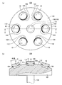
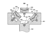
- FIG. 1 is a schematic view showing a structure of a lens holder according to Embodiment 1 of the present invention.
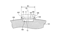
- FIG. 2 is an enlarged sectional view of the lens receiving portion shown in FIG.
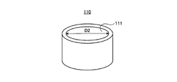
- FIG. 3 is a perspective view showing a ring that is additionally used when holding the lens in the lens receiving portion shown in FIG.
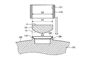
- FIG. 4 is a cross-sectional view for explaining an adhesive application step, a lens placement step, and an alignment step in the lens holding method according to Embodiment 1 of the present invention.
- FIG. 5 is a cross-sectional view for explaining an alignment step in the lens holding method according to Embodiment 1 of the present invention.
- FIG. 1 is a schematic view showing a structure of a lens holder according to Embodiment 1 of the present invention.
- FIG. 2 is an enlarged sectional view of the lens receiving portion shown in FIG.
- FIG. 3 is a perspective view showing a ring that is additionally used when holding the lens in the lens receiving portion shown in FIG.
- FIG. 6 is a cross-sectional view showing the structure of the lens holder according to Variation 1-1 of Embodiment 1 of the present invention.
- FIG. 7 is a cross-sectional view showing the structure of the lens holder according to Modification 1-2 of Embodiment 1 of the present invention.
- FIG. 8 is a cross-sectional view showing the structure of a lens holder according to Embodiment 2 of the present invention.
- FIG. 9 is a cross-sectional view for explaining an alignment step in the lens holding method according to Embodiment 2 of the present invention.
- FIG. 10 is a view showing the structure of a lens holder according to Embodiment 3 of the present invention.
- FIG. 11 is a view for explaining an alignment step in the lens holding method according to Embodiment 3 of the present invention.
- FIG. 12 is a view showing the structure of a lens holder according to Embodiment 4 of the present invention.
- FIG. 13 is a view for explaining an alignment step in the lens holding method according to Embodiment 4 of the present invention.
- FIG. 14 is a cross-sectional view showing the structure of the lens holder according to Embodiment 5 of the present invention.
- FIG. 15 is a partial cross-sectional view showing an enlarged lens receiving portion shown in FIG.
- FIG. 16 is a partial cross-sectional view for illustrating an adhesive application step, a lens placement step, and an alignment step in the lens holding method according to Embodiment 5 of the present invention.
- FIG. 12 is a view showing the structure of a lens holder according to Embodiment 4 of the present invention.
- FIG. 13 is a view for explaining an alignment step in the lens holding method according to Embodiment 4 of the present invention.
- FIG. 14 is a cross-sectional view showing the structure of the lens holder according to Embodiment
- FIG. 17 is a partial cross-sectional view for illustrating a lens receiving portion attaching process in the lens holding method according to Embodiment 5 of the present invention.
- FIG. 18 is a cross-sectional view showing a structure of a lens receiving portion in a modification 5-1 of the fifth embodiment of the present invention.
- FIG. 1 is a schematic view showing a structure of a lens holder according to Embodiment 1 of the present invention.
- FIG. 1 (a) is a top view showing a state in which a plurality of lenses to be processed are held by the lens holder
- FIG. 1 (b) is a cross-sectional view taken along the line AA of FIG. It is.
- the lens holder 100 according to Embodiment 1 of the present invention includes a base 101 having a shaft 102 and a plurality of lens receivers provided to protrude from the surface 103 of the base 101. And 104.
- the plurality of lenses 10 to be processed are respectively held by the lens receiving portions 104 via the adhesive 112.
- FIG. 1A shows an example in which seven lens receiving portions 104 are provided, three or more lens receiving portions 104 may be provided. These lens receivers 104 are arranged on the surface of the base 101 so as to be rotationally symmetrical.
- the base 101 is a metal or alloy member in the shape of a part of a sphere, and the surface 103 of the base 101 has a convex spherical shape.
- the shaft portion 102 is provided on the surface opposite to the surface 103 coaxially with the rotation center of the base portion 101.
- FIG. 2 is a cross-sectional view showing the lens receiving portion 104 in an enlarged manner.
- the lens receiving portion 104 has a cylindrical shape having an outer diameter substantially equal to the outer diameter D1 of the lens 10.
- the lens receiving portion 104 is provided such that the rotational symmetry axis R1 of the cylinder is orthogonal to the surface in contact with the same spherical surface 103 'as the surface 103 at the position of the rotational symmetry axis R1.
- the lens receiving surface 105 which is the upper end surface of the lens receiving portion 104 abuts on the supported surface 12 which is the end surface of the lens 10 opposite to the processing surface 11 to support the lens 10.
- the lens receiving surface 105 has a spherical center on the rotational symmetry axis R1 corresponding to the convex spherical support surface 12, and has a concave spherical shape having a curvature radius substantially equal to that of the support surface 12 I am
- the shape of the lens receiving surface 105 is not limited to the concave spherical shape.
- the lens receiving surface 105 may have a convex spherical shape corresponding to the shape of the supported surface 12.
- the lens receiving surface 105 may be planar.
- the height of the outer periphery 106 of the lens receiving surface 105 is higher than the surface 103 of the base 101. Thereby, regardless of the thickness of the edge (edge) of the lens 10, it is possible to prevent a processing tool such as a grindstone from coming into contact with the surface 103 of the base 101 during processing of the lens 10.
- the height of the inner periphery 107 of the lens receiving surface 105 viewed from the surface 103 of the base 101 is determined by the height of the outer periphery 106, the radius of curvature of the lens receiving surface 105, and the radial width of the lens receiving portion 104. Ru.
- the inner circumference 107 may be lower than the surface 103 of the base 101.
- the inner opening 108 of the lens receiving portion 104 is excavated so that the lens 10 does not interfere with the base 101 according to the radius of curvature of the supported surface 12 of the lens 10.
- the position of the bottom of the opening 108 may be lower than the surface 103 of the base 101.
- FIG. 3 is a perspective view showing a ring 110 which is a supporting means used in an auxiliary manner when holding the lens 10 in the lens receiving portion 104.
- the ring 110 is a cylindrical member having an inner diameter D2 substantially equal to the outer diameter of the lens receiving portion 104 (ie, the outer diameter D1 of the lens 10), and is attached to and detached from the lens receiving portion 104 Mating) is possible.
- the distance from the rotational symmetry axis R1 is equal to the periphery of the lens receiving portion 104 in parallel with the rotational symmetry axis R1 (see FIG. 2) of the lens receiving portion 104.
- the alignment surface of the lens 10 is formed by the inner circumferential surface 111 of the ring 110.
- FIG. 4 is a cross-sectional view for explaining an adhesive application step, a lens mounting step, and a positioning step in the lens holding method according to the first embodiment.
- FIG. 5 is a cross-sectional view for explaining the alignment process.
- an adhesive 112 such as wax or an ultraviolet curing resin is applied to the lens receiving surface 105.
- the adhesive 112 may be applied to the supported surface 12 side of the lens 10 or may be applied to both the supported surface 12 and the lens receiving surface 105.
- the lens 10 is placed on the lens receiving surface 105, and both are brought into contact with each other via the adhesive 112. At this time, it is preferable to adjust the position of the lens 10 so that the outer periphery of the lens 10 and the outer periphery of the lens receiving portion 104 substantially coincide with each other.
- the ring 110 is covered from above the lens 10 and fitted in the lens receiving portion 104, and the outer peripheral surface of the lens 10 and the outer peripheral surface of the lens receiving portion 104 are brought into contact with the inner peripheral surface 111 of the ring 110.
- the state in which the lens 10 is aligned with the lens receiving portion 104 is maintained.
- the adhesive 112 is cured.
- the adhesive 112 is cooled and cured.
- an ultraviolet curing resin is used as the adhesive 112
- the adhesive 112 is irradiated with ultraviolet through the lens 10 to be cured.
- the lens 10 is held in alignment with the lens receiving portion 104.
- the ring 110 is removed.
- each lens receiving unit 104 provided in the lens holder 100 By performing such an operation on each lens receiving unit 104 provided in the lens holder 100, the lenses 10 are held by all the lens receiving units 104 (see FIG. 1).
- the lens holder 100 is attached to a lens processing device (not shown) so that the shaft 102 can rotate.
- a processing tool having a processing surface having a spherical (for example, concave spherical) shape with a desired curvature is brought into contact with the processing surface 11 of the lens 10, and the processing tool is rotated.
- the processing surface 11 of each lens 10 is polished or ground in a spherical shape (for example, a convex spherical shape) corresponding to the shape of the processing surface.
- the adhesive 112 is dissolved using an organic solvent or the like, and the lens 10 is peeled off from the lens receiving portion 104.
- the lens 10 is peeled off from the lens receiving portion 104.
- the lens receiving portion 104 is provided to protrude from the surface 103 of the base 101, and the lens 10 is held on the lens receiving surface 105 of the lens receiving portion 104. Regardless of the thickness of the edge portion 10, the lens 10 can be held by the lens holder 100 for processing.
- the lens 10 is positioned by fitting the ring 110 to the lens receiving portion 104 and the adhesive 112 is cured in this state. It can be fixed at an appropriate position. Therefore, even when the edge of the lens 10 is thin, the lens receiving portion 104 can be reliably held without causing positional deviation.
- the lens receiving portion 104 is formed in a cylindrical shape, and the lens receiving surface 105 is brought into contact with part of the supported surface 12 of the lens 10, so the lens 10 is bonded to the lens receiving surface 105. Strain can be reduced.
- the surface 103 of the base 101 in order to grind or polish the processing surface 11 of the lens 10 into a convex spherical shape, the surface 103 of the base 101 is convex spherical so that the plurality of lens receiving surfaces 105 are arranged in a convex shape.
- the surface 103 of the base 101 may be formed in a concave spherical shape so that the plurality of lens receiving surfaces 105 are arranged in a concave shape.
- the shape of the surface 103 of the base 101 is not particularly limited, and may not necessarily be spherical.
- the surface 103 of the base 101 may be a polyhedron, and one lens receiving portion 104 may be provided on each surface.
- FIG. 6 is a cross-sectional view showing the structure of the lens holder according to Modification 1-1.
- the lens holder 120 according to the modification 1-1 includes a plurality of lens receiving portions 121 provided on the surface 103 of the base 101. In FIG. 6, only one lens receiving portion 121 is shown enlarged. Further, the structure of the base portion 101 is the same as that of the first embodiment.
- the lens receiving portion 121 includes cylindrically shaped projecting portions 122 and 123 provided coaxially and doubly. Among these, the outer diameter of the outermost protrusion 122 is approximately equal to the outer diameter of the lens 10 to be held.
- the lens receiving surfaces 124 and 125 which are the upper end surfaces of the protrusions 122 and 123, abut the supported surface 12 of the lens 10 to support the lens 10.
- the lens receiving surfaces 124 and 125 have a common spherical center on the rotational symmetry axis R2 of the protrusion 122 on the outer peripheral side, and have a concave spherical shape having a curvature radius substantially equal to that of the supported surface 12 There is no.
- the position of the lens receiving surfaces 124 and 125 is not particularly limited as long as the outer periphery 126 of the outer lens receiving surface 124 is higher than the surface 103 of the base 101.
- the inner lens receiving surface 125 may be lower than the surface 103.
- the lens 10 can be obtained. It is possible to support the lens 10 stably without causing bending or the like.
- the lens receiving portion 121 is configured by the double cylindrically shaped projecting portions 122 and 123, but the number of cylinders may be three or more. Further, instead of the protruding portion 123 on the inner peripheral side, a cylindrical protruding portion may be disposed. In this case, the upper end surface of the cylindrical protrusion is formed into a concave spherical shape having a common spherical center with the lens receiving surface 124 of the outer peripheral protrusion 122 and having a radius of curvature substantially equal to that of the supported surface 12 .
- FIG. 7 is a cross-sectional view showing the structure of the lens holder according to Modification 1-2.
- the lens holder 130 according to the modification 1-2 includes a plurality of lens receiving portions 131 provided on the surface of the base 101.
- the structure of the base portion 101 is the same as that of the first embodiment.
- the lens receiving portion 131 has a cylindrical shape whose outer diameter is substantially equal to the outer diameter of the lens 10. Further, a lens receiving surface 132 which is an upper end surface of the lens receiving portion 131 is in contact with the supported surface 12 of the lens 10 to support the lens 10.
- the lens receiving surface 132 has a spherical center on the rotationally symmetric axis R3 of the outer peripheral surface of the lens receiving portion 131, and has a concave spherical shape having a radius of curvature substantially equal to that of the supported surface 12 .
- the position of the lens receiving surface 132 is not particularly limited as long as its outer periphery 133 is at a position higher than the surface 103 of the base 101.
- the central portion 134 of the lens receiving surface 132 may be lower than the surface 103 depending on the diameter and the radius of curvature of the lens receiving surface 132.
- the lens receiving portion 131 By making the lens receiving portion 131 cylindrical, the lens receiving surface 132 can be brought into contact with the entire supported surface 12 to hold the lens 10 stably.
- the lens holder 130 can be manufactured in a simple process.
- suction holes opened in the lens receiving surface 105 are provided in the lens receiving portion 104 and the base 101, and after the positions of the outer circumferences of the lens 10 and the lens receiving surface 105 are aligned, the pressure of the suction holes is reduced.
- the adhesive 112 may be cured in a state of vacuum suction to the lens receiving surface 105.
- FIG. 8 is a cross-sectional view showing the structure of a lens holder according to Embodiment 2 of the present invention.
- the lens holder 200 according to Embodiment 2 includes a base 201 and a plurality of lens receivers 104 provided to project from the surface 202 of the base 201. Note that FIG. 8 shows only one lens receiving portion 104 in an enlarged manner.
- the base portion 201 is a member made of metal or alloy which is in the shape of a part of a sphere, similarly to the base portion 101 shown in FIG. 1 (b).
- the surface 202 of the base 201 is spherical, and on the opposite side of the surface 202, a shaft (not shown) coaxial with the rotation center of the base 201 is provided.
- the structure of the lens receiving portion 104 is the same as that of the first embodiment. However, in the second embodiment, the lens receiving portion 104 contacts the lens receiving surface 105 to a region inside the outer periphery of the supported surface 22 of the lens 20. The lens 20 is brought into contact, and the lens 20 having a diameter larger than the outer diameter of the lens receiving portion 104 is held.
- An annular groove 203 having an inner diameter larger than the outer diameter of the lens receiving portion 104 coaxial with the lens receiving portion 104 is formed around each lens receiving portion 104.
- the groove portion 203 is used when the lens receiving portion 104 holds the lens 20 as described later.
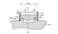
- FIG. 9 is a cross-sectional view for explaining an alignment step in the lens holding method according to the second embodiment.
- the ring 210 is used as an auxiliary supporting means when holding the lens 20 in the lens receiving portion 104.
- the ring 210 is a cylindrical member whose inner diameter is substantially equal to the outer diameter D 3 of the lens 20 and which can be fitted to the groove portion 203.
- the alignment surface of the lens 20 parallel to the rotational symmetry axis R1 of the lens reception portion 104 and having the same distance from the rotational symmetry axis R1 is provided around the lens reception portion 104.
- the inner circumferential surface 211 of the ring 210 is provided around the lens reception portion 104.
- an adhesive 212 such as wax or an ultraviolet curable resin is applied to the lens receiving surface 105 (or the supported surface 22 of the lens 20). Then, with the supported surface 22 of the lens 20 directed toward the lens receiving surface 105, the lens 20 is placed on the lens receiving surface 105, and both are brought into contact with each other via the adhesive 212.
- the ring 210 is covered from above the lens 20 and fitted in the groove portion 203, and the outer peripheral surface of the lens 20 is brought into contact with the inner peripheral surface 211 of the ring 210 to position the lens 20 with respect to the lens receiving portion 104. Make a match. After curing the adhesive 212 in this state, the ring 210 is removed. Thereby, the lens holder 200 in which the lens 20 is held at an appropriate position can be obtained.
- the lens receiving portion 104 it is possible to process the lens 20 by holding the lens 20 having a diameter larger than the outer diameter of the lens receiving portion 104 by the lens receiving portion 104.
- the lens receiving portion 121 in the modified example 1-1 and the lens receiving portion 131 in the modified example 1-2 may be applied to the second embodiment.
- FIG. 10 (a) is a top view showing the structure of the lens holder according to Embodiment 3 of the present invention
- FIG. 10 (b) is a cross-sectional view taken along the line BB in FIG. 10 (a).
- the lens holder 300 according to the third embodiment includes a base 301 and a plurality of lens receivers 104 provided to project from the surface 302 of the base 301. Note that FIG. 10 shows only one lens receiving portion 104 in an enlarged manner.
- the base portion 301 is a member made of metal or alloy which is in the shape of a part of a sphere, similarly to the base portion 101 shown in FIG. 1 (b).
- the surface 302 of the base 301 is spherical, and the opposite surface of the surface 302 is provided with a shaft (not shown) coaxial with the center of rotation of the base 301.
- the structure of the lens receiving portion 104 is the same as that of the first embodiment.
- at least three pin holes 303 are formed along the outer periphery of the lens receiving portion 104.
- the pin holes 303 are used when the lens receiving portion 104 holds the lens 10 as described later.
- the pin holes 303 may be arranged as evenly as possible.
- three pin holes 303 are arranged so as to be three-fold rotational symmetric with respect to the rotational symmetry axis R1.
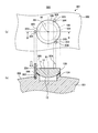
- FIG. 11 (a) is a top view for explaining the alignment step in the lens holding method according to Embodiment 3.
- FIG. 11 (b) is a cross-sectional view taken along the line BB in FIG. 11 (a). It is.
- at least three pins 304 are used as auxiliary supporting means when the lens receiving portion 104 holds the lens 10.
- Each pin 304 is a columnar (for example, cylindrical) member and can be fitted to the pin hole 303. By fitting these pins 304 into the pin holes 303, the distance from the rotational symmetry axis R1 is equal to the at least three locations around the lens reception portion 104 in parallel with the rotational symmetry axis R1 of the lens reception portion 104.
- the alignment indicator 305 of the lens 10 is formed.
- the adhesive 306 is applied to the lens receiving surface 105 (or the supported surface 12 of the lens 10). Then, with the supported surface 12 of the lens 10 directed toward the lens receiving surface 105, the lens 10 is placed on the lens receiving surface 105, and both are brought into contact with each other via the adhesive 306. Further, the pin 304 is inserted into the pin hole 303, and the outer peripheral surface of the lens 10 is brought into contact with the side surface of each pin 304, whereby the lens 10 is aligned with the lens receiving portion 104. After curing the adhesive 306 in this state, the pin 304 is removed. Thereby, the lens holder 300 in which the lens 10 is held at an appropriate position can be obtained.
- the alignment of the lens 10 can be performed with a simple configuration.
- the lens receiving portion 121 in the modified example 1-1 and the lens receiving portion 131 in the modified example 1-2 may be applied to the third embodiment.
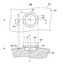
- FIG. 12 (a) is a top view showing the structure of the lens holder according to Embodiment 4 of the present invention
- FIG. 12 (b) is a sectional view taken along the line CC in FIG. 12 (a).
- the lens holder 400 according to Embodiment 4 includes a base 401 and a plurality of lens receivers 104 provided to project from the surface 402 of the base 401. Note that FIG. 12 shows only one lens receiving portion 104 in an enlarged manner.
- the base 401 is a member made of metal or alloy which is in the shape of a part of a sphere, similarly to the base 101 shown in FIG. 1 (b).
- the surface 402 of the base 401 is spherical, and the opposite surface of the surface 402 is provided with a shaft (not shown) coaxial with the center of rotation of the base 401.
- the structure of the lens receiving portion 104 is the same as that of the first embodiment.
- Grooves 403 are formed at predetermined positions near the respective lens receiving portions 104. The groove portion 403 is used when the lens receiving portion 104 holds the lens 10 as described later.
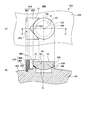
- FIG. 13 (a) is a top view for explaining the alignment step in the lens holding method according to Embodiment 4.
- FIG. 13 (b) is a cross-sectional view taken along the line CC in FIG. 13 (a). It is.
- a V-shaped jig 404 is used as an auxiliary supporting unit when holding the lens 10 in the lens receiving unit 104.
- the V-shaped jig 404 has a main body portion 406 provided with two flat surfaces 405 intersecting in a V-shape, and a leg portion 407 that supports the main body portion 406 and that can be fitted to the groove portion 403.
- the lens 10 is provided in the vicinity of the lens receiving portion 104 in two places which are parallel to the rotational symmetric axis R1 of the lens receiving portion 104 and have the same distance from the rotational symmetric axis R1.
- An alignment surface against which the outer peripheral surface can abut is formed by the two flat surfaces 405.
- the adhesive 408 is applied to the lens receiving surface 105 (or the supported surface 12 of the lens 10). Then, with the supported surface 12 of the lens 10 directed toward the lens receiving surface 105, the lens 10 is placed on the lens receiving surface 105, and both are brought into contact with each other via the adhesive 408. Further, the leg portion 407 of the V-shaped jig 404 is inserted into the groove portion 403, and the outer periphery 13 of the lens 10 is brought into contact with the two flat surfaces 405, thereby aligning the lens 10 with the lens receiving portion 104. After curing the adhesive 408 in this state, the V-shaped jig 404 is removed. Thereby, the lens holder 400 in which the lens 10 is held at an appropriate position can be obtained.
- the alignment of the lens 10 can be easily performed.
- a lens having a diameter larger than the outer diameter of the lens receiving portion 104 is held in the lens receiving portion 104 by changing the position of the two flat surfaces 405 constituting the V-shaped jig 404 and the angle at which the flat surfaces 405 intersect. It is also possible to In this case, only by replacing the V-shaped jig 404 with respect to the groove portion 403, alignment of various lenses having different diameters can be coped with.
- the lens receiving unit 121 in the modified example 1-1 and the lens receiving unit 131 in the modified example 1-2 may be applied to the fourth embodiment.
- FIG. 14 is a cross-sectional view showing the structure of the lens holder according to Embodiment 5 of the present invention.
- the lens holder 500 according to Embodiment 5 includes a base portion 501 and a plurality of lens receiving portions 510 provided to protrude from the surface 503 of the base portion 501.
- FIG. 14 shows a state in which the lens 50 to be processed is held by the lens receiving portions 510 via the adhesive 520.
- 14 shows, as an example, a cross section (a cross section corresponding to the line AA of FIG. 1A) in the case where seven lens receiving portions 510 are provided in the same arrangement as that of FIG. However, three or more lens receiving portions 510 may be provided.
- the base portion 501 is a member made of metal or alloy in the shape of a part of a sphere.
- An axial portion 502 coaxial with the rotation center of the base portion 501 is provided on the surface opposite to the concave spherical surface 503.
- cylindrical countersunk holes 504 are formed at a plurality of locations on the surface 503, and female screw holes 505 are formed in the bottom of each countersunk hole 504.
- FIG. 15 is a partial cross-sectional view showing the lens receiving portion 510 in an enlarged manner.
- the lens receiving portion 510 is configured to be attachable to and detachable from the base portion 501.
- the lens receiving portion 510 is provided in a cylindrical portion 511 having substantially the same outer diameter as the outer diameter D4 of the lens 50, and a bottom portion of the cylindrical portion 511. And an externally threaded portion 512 screwable.
- the lens receiving surface 513 which is the upper end surface of the cylindrical portion 511 is in contact with the supported surface 52 which is the end surface of the lens 50 opposite to the processing surface 51 to support the lens 50.
- the lens receiving surface 513 has a spherical center on the rotational symmetry axis R4 of the outer peripheral surface of the cylindrical portion 511 corresponding to the convex spherical shaped supported surface 52, and the supported surface 52 and the curvature The radius is approximately equal and concave spherical.
- the outer periphery 514 of the lens receiving surface 513 of the lens receiving surface 513 is the surface of the base portion 501 when the lens receiving portion 510 is attached to the base portion 501, from the relationship with the height of the cylindrical portion 511 and the depth of the counterbore 504 formed in the base portion 501. It is set to be higher than 503. Thereby, regardless of the thickness of the edge of the lens 50, it is possible to prevent a processing tool such as a grindstone from coming into contact with the base 501 during processing of the lens 50.
- the height of the central portion 515 of the lens receiving surface 513 is determined by the diameter and the height of the outer periphery 514 and the curvature radius of the lens receiving surface 513. Therefore, when the lens receiving portion 510 is attached to the base portion 501, the height of the central portion 515 may be lower than the surface 503.
- FIG. 16 is a partial cross-sectional view for illustrating an adhesive application step, a lens placement step, and an alignment step in the lens holding method according to the fifth embodiment.
- FIG. 17 is a partial cross-sectional view for explaining the lens holder mounting step.
- the adhesive 520 is applied to the lens receiving surface 513 (or the supported surface 52 of the lens 50) with the lens receiving portion 510 removed from the base 501. Subsequently, the supported surface 52 of the lens 50 is directed to the lens receiving surface 513 side, and the lens 50 is placed on the lens receiving surface 513, and both are brought into contact with each other through the adhesive 520. Alignment of the outer circumferences of the receiving surface 513 is performed. At this time, as in the first embodiment, alignment is achieved by fitting a ring having an inner diameter substantially equal to the outer diameter of the lens receiving surface 513 (that is, the outer diameter D4 of the lens 50) to the cylindrical portion 511 and the lens 50. You may Then, the adhesive 520 is cured in this state.
- the lens receiving portion 510 to which the lens 50 is attached is inserted into each counterbore 504 of the base 501, and the male screw portion 512 is screwed into the female screw hole 505.
- the lens holder 500 in which the lens 50 is held at an appropriate position can be obtained (see FIG. 14).
- the lens receiving portion 510 is attachable to and detachable from the base portion 501, the lens 50 can be easily attached to the lens receiving portion 510.
- the lens 50 is attached in a state where the axis of the lens receiving portion 510 is directed in the vertical direction, it is possible to suppress positional deviation of the lens 50 until the adhesive 520 is cured.
- the surface 503 of the base portion 501 is made concave spherical so that the plurality of lens receiving surfaces 513 are arranged in a concave shape. did.
- the surface 503 of the base portion 501 may be formed into a convex spherical shape such that the plurality of lens receiving surfaces 513 are arranged in a convex shape.
- the shape of the surface 503 of the base 501 is not particularly limited, and may not necessarily be spherical.
- the lens 50 may be supported by an end face having a single or more annular shape.
- the lens receiving portion 530 may be formed of a cylindrical member provided with a lens receiving surface 531 which is an upper end face capable of coming into contact with the supported surface 52 of the lens 50.
- FIG. 18 shows a state in which the lens 50 is attached to the lens receiving surface 531 with an adhesive 520.
- the lens receiving portion 530 may be fixed to the counterbore hole 504 (refer to FIG. 17) using an adhesive. It is also possible to attach it to a conventional recess plate.
- the lens receiving portion 530 and the counterbore 504 may be provided with engagement means to mechanically fix both.
Landscapes
- Engineering & Computer Science (AREA)
- Mechanical Engineering (AREA)
- Grinding And Polishing Of Tertiary Curved Surfaces And Surfaces With Complex Shapes (AREA)
- Lens Barrels (AREA)
Abstract
加工対象のレンズの形状によらず、複数のレンズを同時に保持して研削又は研磨加工を行うことができるレンズ保持具等を提供する。レンズ保持具(100)は、研削又は研磨加工の対象である複数のレンズ(10)を保持するレンズ保持具であって、基部(101)と、該基部(101)の表面(103)の複数箇所に、該表面(103)から突出するようにそれぞれ設けられた複数のレンズ受け部(104)とを備え、各レンズ受け部(104)は、レンズ(10)の一端面である被支持面(12)の少なくとも一部が当接可能なレンズ受け面(105)を有し、該レンズ受け面(105)の外周は表面(103)よりも高い位置に設けられている。
Description
本発明は、レンズの研削又は研磨加工においてレンズを保持するレンズ保持具及びレンズ保持方法に関する。
複数のレンズの端面を同時に研削又は研磨加工する方法として、リセス皿を用いる方法が知られている(例えば、特許文献1~4を参照)。リセス皿とは、球面状をなす基材の表面に、レンズを保持するための複数の座ぐり穴(以下、皿穴という)が形成されたレンズ保持具である。リセス皿を用いたレンズの加工方法においては、各皿穴に加工対象のレンズを保持させ、所望の曲率を有する球面状の加工面が形成された砥石等の加工工具をこれらのレンズに当接させて回転させる。それにより、複数のレンズの端面を同一の曲率の球面状に、一括して研削又は研磨加工することができる。また、リセス皿を用いる場合、レンズを1つずつ加工する場合と比較して安定した加工を行うことができ、加工精度が向上するという利点もある。
特許文献1の図2に例示するように、各レンズは、外周面を皿穴の内周面に嵌合させることにより位置合わせされ、接着剤を用いて固定される。このため、レンズの縁部(所謂コバ)が薄いレンズの場合、皿穴から突出するレンズの部分(即ち、加工対象部分)が僅かとなり、リセス皿の表面と加工工具とのクリアランスが小さくなって干渉が生じるおそれがあった。即ち、リセス皿を用いて加工することができるレンズの形状には制限があった。
本発明は、上記に鑑みてなされたものであって、加工対象のレンズの形状によらず、複数のレンズを同時に保持して研削又は研磨加工を行うことができるレンズ保持具及びレンズ保持方法を提供することを目的とする。
上述した課題を解決し、目的を達成するために、本発明に係るレンズ保持具は、研削又は研磨加工の対象である複数のレンズを保持するレンズ保持具であって、基部と、前記基部の表面の複数箇所に、該表面から突出するようにそれぞれ設けられた複数のレンズ受け部と、を備え、各レンズ受け部は、前記レンズの一端面である被支持面の少なくとも一部と当接可能なレンズ受け面を有し、該レンズ受け面の外周は前記表面よりも高い位置に設けられていることを特徴とする。
上記レンズ保持具において、前記各レンズ受け部は、前記レンズ受け面を上端面とする少なくとも1重の円筒状をなすことを特徴とする。
上記レンズ保持具において、前記各レンズ受け部は、前記レンズ受け面を上端面とする円柱状をなすことを特徴とする。
上記レンズ保持具において、前記各レンズ受け部は、前記レンズ受け面を上端面とする円柱状をなす第1の突出部と、前記レンズ受け面を上端面とし、前記第1の突出部の外周側に設けられた少なくとも1重の円筒状をなす第2の突出部と、からなることを特徴とする。
上記レンズ保持具において、少なくとも3つの前記レンズ受け部が設けられていることを特徴とする。
上記レンズ保持具において、前記各レンズ受け部は、前記基部と一体的に設けられていることを特徴とする。
上記レンズ保持具において、前記各レンズ受け部は、前記基部に対して着脱可能であることを特徴とする。
本発明に係るレンズ保持方法は、基部に複数のレンズ受け部が設けられたレンズ保持具に、研削又は研磨加工の対象である複数のレンズをそれぞれ保持させるレンズ保持方法であって、前記レンズ保持具の各レンズ受け部が有するレンズ受け面と、前記レンズの一端面である被支持面との少なくとも一方に接着剤を塗布する接着剤塗布工程と、前記レンズを前記レンズ受け面上に載置し、前記被支持面と前記レンズ受け面とを前記接着剤を介して当接させるレンズ載置工程と、前記各レンズ受け部に対して前記レンズを位置合わせする位置合わせ工程と、前記接着剤を硬化させる接着剤硬化工程と、を含み、前記各レンズ受け部は前記基部の表面から突出し、前記レンズ受け面の外周は前記表面よりも高い位置に設けられていることを特徴とする。
上記レンズ保持方法において、前記位置合わせ工程は、前記レンズ保持具に対して着脱可能な支持手段であって、該支持手段を前記レンズ保持具に装着した場合に、前記各レンズ受け部の回転対称軸と平行且つ該回転対称軸からの距離が等しい少なくとも2箇所において前記レンズの外周面が当接可能な位置合わせ面又は位置合わせラインが形成される支持手段を、前記レンズ保持具に装着することを特徴とする。
上記レンズ保持方法において、前記支持手段は、前記レンズの外周面と当接可能な内周面を有する円筒状の部材であることを特徴とする。
上記レンズ保持方法において、前記各レンズ受け部は、前記基部に対して着脱可能であり、前記接着剤硬化工程の後で、前記レンズが貼付された前記各レンズ受け部を前記基部に装着する工程をさらに含むことを特徴とする。
本発明によれば、基部の表面から突出するようにレンズ受け部を設け、加工対象のレンズの一端面をレンズ受け面に当接させて該レンズを保持するので、基部の表面と加工工具とのクリアランスを十分に確保することができる。従って、加工対象のレンズの形状によらず、複数のレンズをレンズ保持具に保持させて、同時に研削又は研磨加工を行うことが可能となる。
以下、本発明に係るレンズ保持具及びレンズ保持方法の実施の形態について、図面を参照しながら説明する。なお、これら実施の形態によって本発明が限定されるものではない。また、各図面の記載において、同一部分には同一の符号を付して示している。図面は模式的なものであり、各部の寸法の関係や比率は、現実と異なることに留意する必要がある。図面の相互間においても、互いの寸法の関係や比率が異なる部分が含まれる。
(実施の形態1)
図1は、本発明の実施の形態1に係るレンズ保持具の構造を示す模式図である。このうち、図1(a)は該レンズ保持具に加工対象である複数のレンズを保持させた状態を示す上面図であり、図1(b)は図1(a)のA-A断面図である。図1に示すように、本発明の実施の形態1に係るレンズ保持具100は、軸部102を有する基部101と、該基部101の表面103から突出するように設けられた複数のレンズ受け部104とを備える。加工対象である複数のレンズ10は、これらのレンズ受け部104に接着剤112を介してそれぞれ保持される。なお、図1(a)は、レンズ受け部104を7つ設けた例を示しているが、レンズ受け部104は3つ以上であれば良い。これらのレンズ受け部104は、基部101の表面に、回転対称となるように配置される。
図1は、本発明の実施の形態1に係るレンズ保持具の構造を示す模式図である。このうち、図1(a)は該レンズ保持具に加工対象である複数のレンズを保持させた状態を示す上面図であり、図1(b)は図1(a)のA-A断面図である。図1に示すように、本発明の実施の形態1に係るレンズ保持具100は、軸部102を有する基部101と、該基部101の表面103から突出するように設けられた複数のレンズ受け部104とを備える。加工対象である複数のレンズ10は、これらのレンズ受け部104に接着剤112を介してそれぞれ保持される。なお、図1(a)は、レンズ受け部104を7つ設けた例を示しているが、レンズ受け部104は3つ以上であれば良い。これらのレンズ受け部104は、基部101の表面に、回転対称となるように配置される。
基部101は球体の一部の形状をなす金属又は合金製の部材であり、該基部101の表面103は凸球面状をなしている。軸部102は、表面103の反対側の面に、基部101の回転中心と同軸に設けられている。
図2は、レンズ受け部104を拡大して示す断面図である。レンズ受け部104は、レンズ10の外径D1と外径がほぼ等しい円筒状をなしている。このレンズ受け部104は、円筒の回転対称軸R1が、該回転対称軸R1の位置における表面103と同一の球面103’に接する面と直交するように設けられている。
レンズ受け部104の上端面であるレンズ受け面105は、レンズ10の被加工面11の反対側の端面である被支持面12に当接してレンズ10を支持する。実施の形態1において、レンズ受け面105は、凸球面状の被支持面12に対応して、回転対称軸R1上に球心を有し、被支持面12と曲率半径がほぼ等しい凹球面状をなしている。
なお、上記レンズ受け面105の形状は、凹球面状に限定されない。例えば、被支持面12が凹球面状をなす場合、レンズ受け面105は、該被支持面12の形状に対応する凸球面状であっても良い。或いは、被支持面12が平面状をなす場合、レンズ受け面105を平面状としても良い。
レンズ受け面105の外周106の高さは、基部101の表面103よりも高くなっている。これにより、レンズ10の縁部(コバ)の厚みによらず、レンズ10の加工中に、砥石等の加工工具が基部101の表面103と接触するのを防ぐことができる。なお、基部101の表面103から見たレンズ受け面105の内周107の高さは、外周106の高さとレンズ受け面105の曲率半径と、レンズ受け部104の径方向の幅とによって決定される。従って、内周107が基部101の表面103より低くなることもある。
レンズ受け部104の内側の開口108は、レンズ10の被支持面12の曲率半径に応じて、レンズ10が基部101と干渉しないように掘削されている。開口108の底面の位置は、基部101の表面103より低くても良い。
次に、本発明の実施の形態1に係るレンズ保持方法及びレンズ加工方法を、図3~図5を参照しながら説明する。
図3は、レンズ受け部104にレンズ10を保持させる際に補助的に使用される支持手段であるリング110を示す斜視図である。図3に示すように、リング110は、内径D2がレンズ受け部104の外径(即ち、レンズ10の外径D1)とほぼ等しい円筒状の部材であり、レンズ受け部104に対して着脱(嵌合)可能となっている。リング110をレンズ受け部104に嵌合させることにより、レンズ受け部104の周囲に、レンズ受け部104の回転対称軸R1(図2参照)と平行で、該回転対称軸R1からの距離が等しいレンズ10の位置合わせ面が、リング110の内周面111によって形成される。
図3は、レンズ受け部104にレンズ10を保持させる際に補助的に使用される支持手段であるリング110を示す斜視図である。図3に示すように、リング110は、内径D2がレンズ受け部104の外径(即ち、レンズ10の外径D1)とほぼ等しい円筒状の部材であり、レンズ受け部104に対して着脱(嵌合)可能となっている。リング110をレンズ受け部104に嵌合させることにより、レンズ受け部104の周囲に、レンズ受け部104の回転対称軸R1(図2参照)と平行で、該回転対称軸R1からの距離が等しいレンズ10の位置合わせ面が、リング110の内周面111によって形成される。
図4は、実施の形態1に係るレンズ保持方法のうちの接着剤塗布工程、レンズ載置工程、及び位置合わせ工程を説明するための断面図である。また、図5は、同位置合わせ工程を説明するための断面図である。
各レンズ受け部104にレンズ10を保持させる際には、まず、図4に示すように、レンズ受け面105に、ワックスや紫外線硬化樹脂等の接着剤112を塗布する。なお、接着剤112は、レンズ10の被支持面12側に塗布しても良いし、被支持面12及びレンズ受け面105の両方に塗布しても良い。
続いて、レンズ10の被支持面12をレンズ受け面105側に向けて、レンズ10をレンズ受け面105上に載置し、接着剤112を介して両者を当接させる。この際、レンズ10の外周とレンズ受け部104の外周とが概ね一致するように、レンズ10の位置を調節すると良い。
続いて、リング110をレンズ10の上方から被せてレンズ受け部104に嵌合させ、レンズ10の外周面及びレンズ受け部104の外周面をリング110の内周面111に当接させる。これにより、図5に示すように、レンズ10がレンズ受け部104に対して位置合わせされた状態が維持される。
続いて、接着剤112を硬化させる。例えば、接着剤112としてワックスを用いた場合、接着剤112を冷却して硬化させる。また、接着剤112として紫外線硬化樹脂を用いた場合、レンズ10を介して接着剤112に紫外線を照射して硬化させる。それにより、レンズ10がレンズ受け部104に位置合わせされた状態で保持される。接着剤112の硬化後、リング110を抜去する。
このような作業を、レンズ保持具100に設けられた各レンズ受け部104に対して行うことにより、全てのレンズ受け部104にレンズ10を保持させる(図1参照)。
続いて、レンズ保持具100を、軸部102が回転可能となるようにレンズ加工装置(図示せず)に取り付ける。そして、所望の曲率の球面状(例えば凹球面状)をなす加工面が形成された加工工具をレンズ10の被加工面11に当接させ、該加工工具を回転させる。それにより、各レンズ10の被加工面11が、加工面の形状に対応した球面状(例えば凸球面状)に研磨又は研削される。
レンズ10の加工終了後、有機溶剤等を用いて接着剤112を溶解させ、レンズ10をレンズ受け部104から剥離する。それにより、被加工面11が同一の曲率の球面状に研磨された複数のレンズ10を同時に得ることができる。
以上説明したように、実施の形態1によれば、基部101の表面103から突出するようにレンズ受け部104を設け、該レンズ受け部104のレンズ受け面105においてレンズ10を保持するので、レンズ10の縁部の厚みによらず、レンズ10をレンズ保持具100に保持して加工を行うことが可能となる。
また、実施の形態1によれば、リング110をレンズ受け部104に嵌合させることによりレンズ10の位置合わせを行い、この状態で接着剤112を硬化させるので、レンズ10をレンズ受け部104の適切な位置に固定することができる。従って、レンズ10の縁部が薄い場合であっても、位置ずれを生じさせることなく、レンズ受け部104に確実に保持させることが可能となる。
また、実施の形態1によれば、レンズ受け部104を円筒状とし、レンズ10の被支持面12の一部にレンズ受け面105を当接させるので、レンズ10をレンズ受け面105に接着した際のひずみを少なくすることができる。
なお、実施の形態1においては、レンズ10の被加工面11を凸球面状に研削又は研磨するため、複数のレンズ受け面105が凸状に並ぶように、基部101の表面103を凸球面状とした。しかしながら、レンズ10の被加工面11を凹球面状に研削又は研磨する場合には、複数のレンズ受け面105が凹状に並ぶように、基部101の表面103を凹球面状にすれば良い。また、複数のレンズ受け面105が被加工面11の加工形状(曲率)に対応して並んでいれば、基部101の表面103の形状は特に限定されず、必ずしも球面状である必要はない。例えば、基部101の表面103を多面体とし、各面にレンズ受け部104を1つずつ設けても良い。
(変形例1-1)
次に、本発明の実施の形態1の変形例1-1について説明する。
図6は、変形例1-1に係るレンズ保持具の構造を示す断面図である。図6に示すように、変形例1-1に係るレンズ保持具120は、基部101の表面103に設けられた複数のレンズ受け部121を備える。なお、図6においては、1つのレンズ受け部121のみを拡大して示している。また、基部101の構造については、実施の形態1と同様である。
次に、本発明の実施の形態1の変形例1-1について説明する。
図6は、変形例1-1に係るレンズ保持具の構造を示す断面図である。図6に示すように、変形例1-1に係るレンズ保持具120は、基部101の表面103に設けられた複数のレンズ受け部121を備える。なお、図6においては、1つのレンズ受け部121のみを拡大して示している。また、基部101の構造については、実施の形態1と同様である。
レンズ受け部121は、同軸且つ2重に設けられた円筒状をなす突出部122、123を備える。このうち、最外周の突出部122の外径は、保持されるレンズ10の外径とほぼ等しい。また、突出部122、123の上端面であるレンズ受け面124、125は、レンズ10の被支持面12に当接してレンズ10を支持する。変形例1-1において、レンズ受け面124、125は、外周側の突出部122の回転対称軸R2上に共通の球心を有し、被支持面12と曲率半径がほぼ等しい凹球面状をなしている。
レンズ受け面124、125の位置は、外側のレンズ受け面124の外周126が基部101の表面103よりも高い位置にあれば、特に限定されない。例えば、被支持面12の曲率半径によっては、内側のレンズ受け面125が表面103より低くなる場合もある。
このように、レンズ10の周縁部を支持する円筒状の突出部122の内周側に、さらに円筒状の突出部123を設けることにより、レンズ10の径が大きい場合であっても、レンズ10に撓み等を生じさせることなく、安定してレンズ10を支持することが可能となる。
なお、変形例1-1においては、2重の円筒状をなす突出部122、123によってレンズ受け部121を構成しているが、円筒を3重以上にしても良い。また、内周側の突出部123の代わりに、円柱状をなす突出部を配置しても良い。この場合、円柱状をなす突出部の上端面を、外周側の突出部122のレンズ受け面124と共通の球心を有し、被支持面12と曲率半径がほぼ等しい凹球面状に形成する。
(変形例1-2)
次に、本発明の実施の形態1の変形例1-2について説明する。
図7は、変形例1-2に係るレンズ保持具の構造を示す断面図である。図7に示すように、変形例1-2に係るレンズ保持具130は、基部101の表面に設けられた複数のレンズ受け部131を備える。なお、図7においては、1つのレンズ受け部131のみを拡大して示している。また、基部101の構造については、実施の形態1と同様である。
次に、本発明の実施の形態1の変形例1-2について説明する。
図7は、変形例1-2に係るレンズ保持具の構造を示す断面図である。図7に示すように、変形例1-2に係るレンズ保持具130は、基部101の表面に設けられた複数のレンズ受け部131を備える。なお、図7においては、1つのレンズ受け部131のみを拡大して示している。また、基部101の構造については、実施の形態1と同様である。
レンズ受け部131は、外径がレンズ10の外径とほぼ等しい円柱状をなしている。また、レンズ受け部131の上端面であるレンズ受け面132は、レンズ10の被支持面12に当接してレンズ10を支持する。変形例1-2において、レンズ受け面132は、レンズ受け部131の外周面の回転対称軸R3上に球心を有し、被支持面12と曲率半径がほぼ等しい凹球面状をなしている。
レンズ受け面132の位置は、その外周133が基部101の表面103よりも高い位置にあれば、特に限定されない。例えば、レンズ受け面132の径や曲率半径によっては、レンズ受け面132の中心部134が表面103より低くなる場合もある。
このように、レンズ受け部131を円柱状とすることにより、レンズ受け面132を被支持面12全体に当接させて、レンズ10を安定して保持することができる。また、レンズ受け部131の構造が簡単なので、レンズ保持具130を簡素な工程で作製することが可能となる。
(変形例1-3)
次に、本発明の実施の形態1の変形例1-3について説明する。
上記実施の形態1においては、レンズ10をレンズ保持具100に貼付する際、リング110をレンズ受け部104に嵌合させた状態で接着剤112を硬化させた。しかしながら、レンズ受け部104に対するレンズ10の位置ずれを防止することができれば、必ずしもリング110を用いる必要はない。例えば、レンズ10及びレンズ受け面105の外周同士の位置を合わせた後、両者がずれないように手で押さえた状態で接着剤112を硬化させても良い。或いは、レンズ受け面105に開口する吸引孔をレンズ受け部104及び基部101内に設け、レンズ10及びレンズ受け面105の外周同士の位置を合わせた後で吸引孔を減圧することにより、レンズ10をレンズ受け面105に真空吸着した状態で接着剤112を硬化させても良い。
次に、本発明の実施の形態1の変形例1-3について説明する。
上記実施の形態1においては、レンズ10をレンズ保持具100に貼付する際、リング110をレンズ受け部104に嵌合させた状態で接着剤112を硬化させた。しかしながら、レンズ受け部104に対するレンズ10の位置ずれを防止することができれば、必ずしもリング110を用いる必要はない。例えば、レンズ10及びレンズ受け面105の外周同士の位置を合わせた後、両者がずれないように手で押さえた状態で接着剤112を硬化させても良い。或いは、レンズ受け面105に開口する吸引孔をレンズ受け部104及び基部101内に設け、レンズ10及びレンズ受け面105の外周同士の位置を合わせた後で吸引孔を減圧することにより、レンズ10をレンズ受け面105に真空吸着した状態で接着剤112を硬化させても良い。
(実施の形態2)
次に、本発明の実施の形態2について説明する。
図8は、本発明の実施の形態2に係るレンズ保持具の構造を示す断面図である。図8に示すように、実施の形態2に係るレンズ保持具200は、基部201と、該基部201の表面202から突出するように設けられた複数のレンズ受け部104とを備える。なお、図8は、1つのレンズ受け部104のみを拡大して示している。
次に、本発明の実施の形態2について説明する。
図8は、本発明の実施の形態2に係るレンズ保持具の構造を示す断面図である。図8に示すように、実施の形態2に係るレンズ保持具200は、基部201と、該基部201の表面202から突出するように設けられた複数のレンズ受け部104とを備える。なお、図8は、1つのレンズ受け部104のみを拡大して示している。
基部201は、図1(b)に示す基部101と同様、球体の一部の形状をなす金属又は合金製の部材である。基部201の表面202は球面状をなし、該表面202の反対側の面には、基部201の回転中心と同軸の軸部(図示せず)が設けられている。
レンズ受け部104の構造は実施の形態1と同様であるが、実施の形態2において、レンズ受け部104は、レンズ受け面105をレンズ20の被支持面22の外周よりも内側の領域に当接させ、レンズ受け部104の外径よりも径が大きいレンズ20を保持する。
各レンズ受け部104の周囲には、レンズ受け部104と同軸で、内径がレンズ受け部104の外径よりも大きい円環状の溝部203が形成されている。この溝部203は、後述するように、レンズ受け部104にレンズ20を保持させる際に用いられる。
図9は、実施の形態2に係るレンズ保持方法のうちの位置合わせ工程を説明するための断面図である。実施の形態2においては、レンズ受け部104にレンズ20を保持させる際の補助的な支持手段として、リング210を用いる。リング210は、内径がレンズ20の外径D3とほぼ等しく、溝部203に対して嵌合可能な円筒状の部材である。リング210を溝部203に嵌合させることにより、レンズ受け部104の周囲に、レンズ受け部104の回転対称軸R1と平行で、該回転対称軸R1からの距離が等しいレンズ20の位置合わせ面が、リング210の内周面211によって形成される。
レンズ受け部104にレンズ20を保持させる際には、ワックスや紫外線硬化樹脂等の接着剤212をレンズ受け面105(又はレンズ20の被支持面22)に塗布する。そして、レンズ20の被支持面22をレンズ受け面105側に向けて、レンズ20をレンズ受け面105上に載置し、接着剤212を介して両者を当接させる。
さらに、リング210をレンズ20の上方から被せて溝部203に嵌合させ、レンズ20の外周面をリング210の内周面211に当接させることにより、レンズ受け部104に対してレンズ20の位置合わせを行う。この状態で接着剤212を硬化させた後、リング210を抜去する。それにより、適切な位置にレンズ20が保持されたレンズ保持具200を得ることができる。
以上説明したように、実施の形態2によれば、レンズ受け部104の外径よりも径が大きいレンズ20をレンズ受け部104に保持させて、レンズ20の加工を行うことができる。
なお、レンズ受け部104の代わりに、変形例1-1におけるレンズ受け部121や、変形例1-2におけるレンズ受け部131を実施の形態2に適用しても良い。
なお、レンズ受け部104の代わりに、変形例1-1におけるレンズ受け部121や、変形例1-2におけるレンズ受け部131を実施の形態2に適用しても良い。
(実施の形態3)
次に、本発明の実施の形態3について説明する。
図10(a)は、本発明の実施の形態3に係るレンズ保持具の構造を示す上面図であり、図10(b)は、図10(a)のB-B断面図である。図10に示すように、実施の形態3に係るレンズ保持具300は、基部301と、該基部301の表面302から突出するように設けられた複数のレンズ受け部104とを備える。なお、図10は、1つのレンズ受け部104のみを拡大して示している。
次に、本発明の実施の形態3について説明する。
図10(a)は、本発明の実施の形態3に係るレンズ保持具の構造を示す上面図であり、図10(b)は、図10(a)のB-B断面図である。図10に示すように、実施の形態3に係るレンズ保持具300は、基部301と、該基部301の表面302から突出するように設けられた複数のレンズ受け部104とを備える。なお、図10は、1つのレンズ受け部104のみを拡大して示している。
基部301は、図1(b)に示す基部101と同様、球体の一部の形状をなす金属又は合金製の部材である。基部301の表面302は球面状をなし、該表面302の反対側の面には、基部301の回転中心と同軸の軸部(図示せず)が設けられている。
レンズ受け部104の構造は、実施の形態1と同様である。各レンズ受け部104の周囲の表面302には、レンズ受け部104の外周に沿って、少なくとも3箇所にピン穴303が形成されている。このピン穴303は、後述するように、レンズ受け部104にレンズ10を保持させる際に用いられる。ピン穴303は、なるべく均等に配置すると良い。図10においては、3つのピン穴303を、回転対称軸R1に対して3回回転対称となるように配置している。
図11(a)は、実施の形態3に係るレンズ保持方法のうちの位置合わせ工程を説明するための上面図であり、図11(b)は、図11(a)のB-B断面図である。実施の形態3においては、レンズ受け部104にレンズ10を保持させる際の補助的な支持手段として、少なくとも3つのピン304を用いる。各ピン304は、柱状(例えば円柱状)をなす部材であり、ピン穴303に対して嵌合可能となっている。これらのピン304をピン穴303に嵌合させることにより、レンズ受け部104の周囲の少なくとも3箇所に、レンズ受け部104の回転対称軸R1と平行で、該回転対称軸R1からの距離が等しいレンズ10の位置合わせの指標305が形成される。
レンズ受け部104にレンズ10を保持させる際には、接着剤306をレンズ受け面105(又はレンズ10の被支持面12)に塗布する。そして、レンズ10の被支持面12をレンズ受け面105側に向けて、レンズ10をレンズ受け面105上に載置し、接着剤306を介して両者を当接させる。さらに、ピン304をピン穴303に挿入し、レンズ10の外周面を各ピン304の側面に当接させることにより、レンズ受け部104に対してレンズ10の位置合わせを行う。この状態で接着剤306を硬化させた後、ピン304を抜去する。それにより、適切な位置にレンズ10が保持されたレンズ保持具300を得ることができる。
以上説明したように、実施の形態3によれば、簡素な構成でレンズ10の位置合わせを行うことができる。
なお、レンズ受け部104の外周106と同軸で、外周106よりも径が大きい円に沿って3つ以上のピン穴303を配置することにより、レンズ受け部104の外径よりも径が大きいレンズをレンズ受け部104に保持させることも可能となる。また、レンズ受け部104の代わりに、変形例1-1におけるレンズ受け部121や、変形例1-2におけるレンズ受け部131を実施の形態3に適用しても良い。
なお、レンズ受け部104の外周106と同軸で、外周106よりも径が大きい円に沿って3つ以上のピン穴303を配置することにより、レンズ受け部104の外径よりも径が大きいレンズをレンズ受け部104に保持させることも可能となる。また、レンズ受け部104の代わりに、変形例1-1におけるレンズ受け部121や、変形例1-2におけるレンズ受け部131を実施の形態3に適用しても良い。
(実施の形態4)
次に、本発明の実施の形態4について説明する。
図12(a)は、本発明の実施の形態4に係るレンズ保持具の構造を示す上面図であり、図12(b)は、図12(a)のC-C断面図である。図12に示すように、実施の形態4に係るレンズ保持具400は、基部401と、該基部401の表面402から突出するように設けられた複数のレンズ受け部104とを備える。なお、図12は、1つのレンズ受け部104のみを拡大して示している。
次に、本発明の実施の形態4について説明する。
図12(a)は、本発明の実施の形態4に係るレンズ保持具の構造を示す上面図であり、図12(b)は、図12(a)のC-C断面図である。図12に示すように、実施の形態4に係るレンズ保持具400は、基部401と、該基部401の表面402から突出するように設けられた複数のレンズ受け部104とを備える。なお、図12は、1つのレンズ受け部104のみを拡大して示している。
基部401は、図1(b)に示す基部101と同様、球体の一部の形状をなす金属又は合金製の部材である。基部401の表面402は球面状をなし、該表面402の反対側の面には、基部401の回転中心と同軸の軸部(図示せず)が設けられている。
レンズ受け部104の構造は、実施の形態1と同様である。各レンズ受け部104の近傍の所定位置には、溝部403が形成されている。この溝部403は、後述するように、レンズ受け部104にレンズ10を保持させる際に用いられる。
図13(a)は、実施の形態4に係るレンズ保持方法のうちの位置合わせ工程を説明するための上面図であり、図13(b)は、図13(a)のC-C断面図である。実施の形態4においては、レンズ受け部104にレンズ10を保持させる際の補助的な支持手段として、V字治具404を用いる。V字治具404は、V字状に交わる2つの平面405が設けられた本体部406と、該本体部406を支持する、溝部403に対して嵌合可能な脚部407とを有する。脚部407を溝部403に嵌合させることにより、レンズ受け部104の近傍に、レンズ受け部104の回転対称軸R1と平行で、該回転対称軸R1からの距離が等しい2箇所でレンズ10の外周面が当接可能な位置合わせ面が、2つの平面405によって形成される。
レンズ受け部104にレンズ10を保持させる際には、接着剤408をレンズ受け面105(又はレンズ10の被支持面12)に塗布する。そして、レンズ10の被支持面12をレンズ受け面105側に向けて、レンズ10をレンズ受け面105上に載置し、接着剤408を介して両者を当接させる。さらに、V字治具404の脚部407を溝部403に挿入し、レンズ10の外周13を2つの平面405に当接させることにより、レンズ受け部104に対してレンズ10の位置合わせを行う。この状態で接着剤408を硬化させた後、V字治具404を抜去する。それにより、適切な位置にレンズ10が保持されたレンズ保持具400を得ることができる。
以上説明したように、実施の形態4によれば、レンズ10の位置合わせを容易に行うことができる。
なお、V字治具404を構成する2つの平面405の位置やこれらの平面405が交わる角度を変更することにより、レンズ受け部104の外径よりも径が大きいレンズをレンズ受け部104に保持させることも可能である。この場合、溝部403に対してV字治具404を付け替えるだけで、径が異なる種々のレンズの位置合わせに対応することができる。また、レンズ受け部104の代わりに、変形例1-1におけるレンズ受け部121や、変形例1-2におけるレンズ受け部131を実施の形態4に適用しても良い。
なお、V字治具404を構成する2つの平面405の位置やこれらの平面405が交わる角度を変更することにより、レンズ受け部104の外径よりも径が大きいレンズをレンズ受け部104に保持させることも可能である。この場合、溝部403に対してV字治具404を付け替えるだけで、径が異なる種々のレンズの位置合わせに対応することができる。また、レンズ受け部104の代わりに、変形例1-1におけるレンズ受け部121や、変形例1-2におけるレンズ受け部131を実施の形態4に適用しても良い。
(実施の形態5)
次に、本発明の実施の形態5について説明する。
図14は、本発明の実施の形態5に係るレンズ保持具の構造を示す断面図である。図14に示すように、実施の形態5に係るレンズ保持具500は、基部501と、該基部501の表面503から突出するように設けられた複数のレンズ受け部510とを備える。なお、図14は、加工対象のレンズ50を、接着剤520を介して各レンズ受け部510に保持させた状態を示している。また、図14は、一例として、図1(a)と同様の配置でレンズ受け部510を7つ設けた場合の一断面(図1(a)のA-A線に対応する断面)を示しているが、レンズ受け部510は3つ以上であれば良い。
次に、本発明の実施の形態5について説明する。
図14は、本発明の実施の形態5に係るレンズ保持具の構造を示す断面図である。図14に示すように、実施の形態5に係るレンズ保持具500は、基部501と、該基部501の表面503から突出するように設けられた複数のレンズ受け部510とを備える。なお、図14は、加工対象のレンズ50を、接着剤520を介して各レンズ受け部510に保持させた状態を示している。また、図14は、一例として、図1(a)と同様の配置でレンズ受け部510を7つ設けた場合の一断面(図1(a)のA-A線に対応する断面)を示しているが、レンズ受け部510は3つ以上であれば良い。
基部501は、球体の一部の形状をなす金属又は合金製の部材である。凹球面状をなす表面503の反対側の面には、基部501の回転中心と同軸の軸部502が設けられている。また、表面503の複数箇所には、円柱状の座ぐり穴504が形成され、各座ぐり穴504の底面には雌ネジ穴505が形成されている。
図15は、レンズ受け部510を拡大して示す一部断面図である。レンズ受け部510は、基部501に対して着脱可能な構成となっており、レンズ50の外径D4と外径がほぼ等しい円柱部511と、該円柱部511の底部に設けられ、雌ネジ穴505と螺合可能な雄ネジ部512とを有する。
円柱部511の上端面であるレンズ受け面513は、レンズ50の被加工面51の反対側の端面である被支持面52に当接してレンズ50を支持する。実施の形態5において、レンズ受け面513は、凸球面状の被支持面52に対応して、円柱部511の外周面の回転対称軸R4上に球心を有し、被支持面52と曲率半径がほぼ等しい凹球面状をなしている。
円柱部511の高さは、基部501に形成された座ぐり穴504の深さとの関係から、レンズ受け部510を基部501に装着した際に、レンズ受け面513の外周514が基部501の表面503よりも高くなるように設定されている。これにより、レンズ50の縁部の厚みによらず、レンズ50の加工中に、砥石等の加工工具が基部501と接触するのを防ぐことができる。なお、レンズ受け面513の中心部515の高さは、外周514の径及び高さと、レンズ受け面513の曲率半径とによって決定される。従って、レンズ受け部510を基部501に装着した際に、中心部515の高さが表面503より低くなることもある。
図16は、実施の形態5に係るレンズ保持方法のうちの接着剤塗布工程、レンズ載置工程、及び位置合わせ工程を説明するための一部断面図である。また、図17は、同レンズ受け部装着工程を説明するための一部断面図である。
まず、図16に示すように、基部501からレンズ受け部510を取り外した状態で、レンズ受け面513(又はレンズ50の被支持面52)に接着剤520を塗布する。続いて、レンズ50の被支持面52をレンズ受け面513側に向けて、レンズ50をレンズ受け面513上に載置し、接着剤520を介して両者を当接させると共に、レンズ50及びレンズ受け面513の外周同士の位置合わせを行う。このとき、実施の形態1と同様に、内径がレンズ受け面513の外径(即ち、レンズ50の外径D4)とほぼ等しいリングを円柱部511及びレンズ50に嵌合させることにより、位置合わせを行っても良い。そして、この状態で接着剤520を硬化させる。
続いて、図17に示すように、レンズ50が貼付されたレンズ受け部510を、基部501の各座ぐり穴504に挿入し、雄ネジ部512を雌ネジ穴505に螺合させる。それにより、適切な位置にレンズ50が保持されたレンズ保持具500を得ることができる(図14参照)。
以上説明したように、実施の形態5によれば、基部501に対してレンズ受け部510を着脱可能とするので、レンズ50をレンズ受け部510に貼付する作業を容易に行うことができる。特に、レンズ受け部510の軸を鉛直方向に向けた状態でレンズ50を貼付するので、接着剤520が硬化するまでの間におけるレンズ50の位置ずれを抑制することが可能となる。
なお、実施の形態5においては、レンズ50の被加工面51を凹球面状に研削又は研磨するため、複数のレンズ受け面513が凹状に並ぶように、基部501の表面503を凹球面状とした。しかしながら、レンズ50の被加工面51を凸球面状に研削又は研磨する場合には、複数のレンズ受け面513が凸状に並ぶように、基部501の表面503を凸球面状にすれば良い。また、複数のレンズ受け面513が被加工面51の加工形状(曲率)に対応して並んでいれば、基部501の表面503の形状は特に限定されず、必ずしも球面状である必要はない。
また、実施の形態5においても、実施の形態1や変形例1-1と同様に、1重以上の円環状をなす端面によってレンズ50を支持しても良い。
(変形例5-1)
次に、本発明の実施の形態5の変形例5-1について説明する。
上記実施の形態5においては、雄ネジ部512を雌ネジ穴505に螺合することによりレンズ受け部510を基部501に固定したが、固定手段はこれに限定されない。
次に、本発明の実施の形態5の変形例5-1について説明する。
上記実施の形態5においては、雄ネジ部512を雌ネジ穴505に螺合することによりレンズ受け部510を基部501に固定したが、固定手段はこれに限定されない。
例えば、図18に示すように、レンズ50の被支持面52と当接可能な上端面であるレンズ受け面531が設けられた円柱状の部材によって、レンズ受け部530を構成しても良い。なお、図18は、接着剤520によりレンズ50をレンズ受け面531に貼付した状態を示している。このように、レンズ受け部530にネジ部を設けない場合、接着剤を用いてレンズ受け部530を座ぐり穴504(図17参照)に固定すれば良く、基部の表面に座ぐり穴を設けただけの従来のリセス皿に取り付けることも可能である。或いは、レンズ受け部530及び座ぐり穴504に係合手段を設け、両者を機械的に固定しても良い。
10、20、50 レンズ
11、51 被加工面
12、22、52 被支持面
13 外周
100、120、130、200、300、400、500 レンズ保持具
101、201、301、401、501 基部
102、502 軸部
103、202、302、402、503 表面
104、121、131、510、530 レンズ受け部
105、124、125、132、513、531 レンズ受け面
106、126、133、514 外周
107 内周
108 開口
110、210 リング
111、211 内周面
112、212、306、408、520 接着剤
122、123 突出部
134、515 中心部
203、403 溝部
303 ピン穴
304 ピン
305 位置合わせの指標
404 V字治具
405 平面
406 本体部
407 脚部
504 座ぐり穴
505 雌ネジ穴
511 円柱部
512 雄ネジ部
11、51 被加工面
12、22、52 被支持面
13 外周
100、120、130、200、300、400、500 レンズ保持具
101、201、301、401、501 基部
102、502 軸部
103、202、302、402、503 表面
104、121、131、510、530 レンズ受け部
105、124、125、132、513、531 レンズ受け面
106、126、133、514 外周
107 内周
108 開口
110、210 リング
111、211 内周面
112、212、306、408、520 接着剤
122、123 突出部
134、515 中心部
203、403 溝部
303 ピン穴
304 ピン
305 位置合わせの指標
404 V字治具
405 平面
406 本体部
407 脚部
504 座ぐり穴
505 雌ネジ穴
511 円柱部
512 雄ネジ部
Claims (11)
- 研削又は研磨加工の対象である複数のレンズを保持するレンズ保持具であって、
基部と、
前記基部の表面の複数箇所に、該表面から突出するようにそれぞれ設けられた複数のレンズ受け部と、
を備え、
各レンズ受け部は、前記レンズの一端面である被支持面の少なくとも一部と当接可能なレンズ受け面を有し、該レンズ受け面の外周は前記表面よりも高い位置に設けられていることを特徴とするレンズ保持具。 - 前記各レンズ受け部は、前記レンズ受け面を上端面とする少なくとも1重の円筒状をなすことを特徴とする請求項1に記載のレンズ保持具。
- 前記各レンズ受け部は、前記レンズ受け面を上端面とする円柱状をなすことを特徴とする請求項1に記載のレンズ保持具。
- 前記各レンズ受け部は、前記レンズ受け面を上端面とする円柱状をなす第1の突出部と、前記レンズ受け面を上端面とし、前記第1の突出部の外周側に設けられた少なくとも1重の円筒状をなす第2の突出部と、からなることを特徴とする請求項1に記載のレンズ保持具。
- 少なくとも3つの前記レンズ受け部が設けられていることを特徴とする請求項1~4のいずれか1項に記載のレンズ保持具。
- 前記各レンズ受け部は、前記基部と一体的に設けられていることを特徴とする請求項1~5のいずれか1項に記載のレンズ保持具。
- 前記各レンズ受け部は、前記基部に対して着脱可能であることを特徴とする請求項1~5のいずれか1項に記載のレンズ保持具。
- 基部に複数のレンズ受け部が設けられたレンズ保持具に、研削又は研磨加工の対象である複数のレンズをそれぞれ保持させるレンズ保持方法であって、
前記レンズ保持具の各レンズ受け部が有するレンズ受け面と、前記レンズの一端面である被支持面との少なくとも一方に接着剤を塗布する接着剤塗布工程と、
前記レンズを前記レンズ受け面上に載置し、前記被支持面と前記レンズ受け面とを前記接着剤を介して当接させるレンズ載置工程と、
前記各レンズ受け部に対して前記レンズを位置合わせする位置合わせ工程と、
前記接着剤を硬化させる接着剤硬化工程と、
を含み、
前記各レンズ受け部は前記基部の表面から突出し、前記レンズ受け面の外周は前記表面よりも高い位置に設けられていることを特徴とするレンズ保持方法。 - 前記位置合わせ工程は、前記レンズ保持具に対して着脱可能な支持手段であって、該支持手段を前記レンズ保持具に装着した場合に、前記各レンズ受け部の回転対称軸と平行且つ該回転対称軸からの距離が等しい少なくとも2箇所において前記レンズの外周面が当接可能な位置合わせ面又は位置合わせの指標が形成される支持手段を、前記レンズ保持具に装着することを特徴とする請求項8に記載のレンズ保持方法。
- 前記支持手段は、前記レンズの外周面と当接可能な内周面を有する円筒状の部材であることを特徴とする請求項9に記載のレンズ保持方法。
- 前記各レンズ受け部は、前記基部に対して着脱可能であり、
前記接着剤硬化工程の後で、前記レンズが貼付された前記各レンズ受け部を前記基部に装着する工程をさらに含むことを特徴とする請求項8に記載のレンズ保持方法。
Priority Applications (2)
| Application Number | Priority Date | Filing Date | Title |
|---|---|---|---|
| CN201480031472.1A CN105263673A (zh) | 2013-10-31 | 2014-05-08 | 透镜保持器具和透镜保持方法 |
| US14/961,369 US20160082564A1 (en) | 2013-10-31 | 2015-12-07 | Lens holding tool and lens holding method |
Applications Claiming Priority (2)
| Application Number | Priority Date | Filing Date | Title |
|---|---|---|---|
| JP2013-227598 | 2013-10-31 | ||
| JP2013227598A JP2015085476A (ja) | 2013-10-31 | 2013-10-31 | レンズ保持具及びレンズ保持方法 |
Related Child Applications (1)
| Application Number | Title | Priority Date | Filing Date |
|---|---|---|---|
| US14/961,369 Continuation US20160082564A1 (en) | 2013-10-31 | 2015-12-07 | Lens holding tool and lens holding method |
Publications (1)
| Publication Number | Publication Date |
|---|---|
| WO2015064129A1 true WO2015064129A1 (ja) | 2015-05-07 |
Family
ID=53003750
Family Applications (1)
| Application Number | Title | Priority Date | Filing Date |
|---|---|---|---|
| PCT/JP2014/062347 Ceased WO2015064129A1 (ja) | 2013-10-31 | 2014-05-08 | レンズ保持具及びレンズ保持方法 |
Country Status (4)
| Country | Link |
|---|---|
| US (1) | US20160082564A1 (ja) |
| JP (1) | JP2015085476A (ja) |
| CN (1) | CN105263673A (ja) |
| WO (1) | WO2015064129A1 (ja) |
Families Citing this family (2)
| Publication number | Priority date | Publication date | Assignee | Title |
|---|---|---|---|---|
| CN108340213A (zh) * | 2018-03-08 | 2018-07-31 | 信阳市宏远光学仪器有限公司 | 一种光学镜片的加工方法、光学镜片的加工装置以及光学镜片 |
| CN112847018B (zh) * | 2021-03-31 | 2024-10-29 | 南阳乐恩光电有限公司 | 一种棱形球面镜用定位盘以及棱形球面镜生产方法 |
Citations (6)
| Publication number | Priority date | Publication date | Assignee | Title |
|---|---|---|---|---|
| US2151233A (en) * | 1937-01-21 | 1939-03-21 | American Optical Corp | Lens blocking |
| JPH0294058U (ja) * | 1989-01-13 | 1990-07-26 | ||
| JPH07299719A (ja) * | 1994-03-11 | 1995-11-14 | Canon Inc | 光学部品の研磨用保持皿 |
| JPH08323605A (ja) * | 1995-05-25 | 1996-12-10 | Otsuka Chem Co Ltd | レンズ研磨加工用治具、該治具を用いるレンズ研磨加工方法及び該治具の製造方法 |
| JP2001062694A (ja) * | 1999-08-24 | 2001-03-13 | Olympus Optical Co Ltd | リセス皿及びその使用方法 |
| DE102006017685A1 (de) * | 2006-04-15 | 2007-10-18 | Carl Zeiss Ag | Vorrichtung zum Bearbeiten, insbesondere zum Schleifen und Polieren, eines Werkstückes |
Family Cites Families (10)
| Publication number | Priority date | Publication date | Assignee | Title |
|---|---|---|---|---|
| US1969219A (en) * | 1932-12-16 | 1934-08-07 | Haussmann Otto Gustave | Workholder for lens blanks |
| US2585287A (en) * | 1949-01-13 | 1952-02-12 | Eastman Kodak Co | Apparatus for chucking blocks of lenses on generating machines |
| US3514908A (en) * | 1967-11-29 | 1970-06-02 | Bausch & Lomb | Process for finishing contact lenses |
| US3968599A (en) * | 1972-12-01 | 1976-07-13 | Harris, Beach & Wilcox | Lens blocking tools |
| US3866660A (en) * | 1972-12-01 | 1975-02-18 | Harris Beach & Wilcox | Method for producing a lens blocking tool |
| JPH02152760A (ja) * | 1988-11-30 | 1990-06-12 | Olympus Optical Co Ltd | リセス皿 |
| US7250197B2 (en) * | 2003-08-25 | 2007-07-31 | Bausch & Lomb Incorporated | Plasma treatment of contact lens and IOL |
| JP2005108365A (ja) * | 2003-10-01 | 2005-04-21 | Ntn Corp | 光学式ピックアップのレンズホルダおよびレンズプロテクタ、ならびにそれらの製造方法 |
| DE102004023036A1 (de) * | 2004-05-06 | 2005-12-29 | Loh Engineering Ag, Oensingen | Blockstück zum Haltern eines optischen Werkstücks, insbesondere einer Brillenlinse, für dessen Bearbeitung |
| CN101585158A (zh) * | 2009-07-03 | 2009-11-25 | 周梁成 | 用于透镜研磨加工的夹具以及透镜加工方法 |
-
2013
- 2013-10-31 JP JP2013227598A patent/JP2015085476A/ja active Pending
-
2014
- 2014-05-08 WO PCT/JP2014/062347 patent/WO2015064129A1/ja not_active Ceased
- 2014-05-08 CN CN201480031472.1A patent/CN105263673A/zh active Pending
-
2015
- 2015-12-07 US US14/961,369 patent/US20160082564A1/en not_active Abandoned
Patent Citations (6)
| Publication number | Priority date | Publication date | Assignee | Title |
|---|---|---|---|---|
| US2151233A (en) * | 1937-01-21 | 1939-03-21 | American Optical Corp | Lens blocking |
| JPH0294058U (ja) * | 1989-01-13 | 1990-07-26 | ||
| JPH07299719A (ja) * | 1994-03-11 | 1995-11-14 | Canon Inc | 光学部品の研磨用保持皿 |
| JPH08323605A (ja) * | 1995-05-25 | 1996-12-10 | Otsuka Chem Co Ltd | レンズ研磨加工用治具、該治具を用いるレンズ研磨加工方法及び該治具の製造方法 |
| JP2001062694A (ja) * | 1999-08-24 | 2001-03-13 | Olympus Optical Co Ltd | リセス皿及びその使用方法 |
| DE102006017685A1 (de) * | 2006-04-15 | 2007-10-18 | Carl Zeiss Ag | Vorrichtung zum Bearbeiten, insbesondere zum Schleifen und Polieren, eines Werkstückes |
Also Published As
| Publication number | Publication date |
|---|---|
| US20160082564A1 (en) | 2016-03-24 |
| JP2015085476A (ja) | 2015-05-07 |
| CN105263673A (zh) | 2016-01-20 |
Similar Documents
| Publication | Publication Date | Title |
|---|---|---|
| US8607435B2 (en) | Tool holder | |
| JP5719478B2 (ja) | 三次元角度調整機構 | |
| CN105182502B (zh) | 一种星载空间反射镜的微应力支撑结构 | |
| CN103676065B (zh) | 大口径透镜的调整固定装置 | |
| KR101800427B1 (ko) | 공작물 팔레트 위치결정 고정장치 | |
| CN103447916B (zh) | 磨削球面垫片的夹具 | |
| WO2015064129A1 (ja) | レンズ保持具及びレンズ保持方法 | |
| RU2542636C1 (ru) | Способ центрировки линзы в оправе и оправа для его осуществления | |
| US11059137B2 (en) | Tool set for use in position adjustment of positioning pins | |
| US11150435B2 (en) | Lens apparatus | |
| CN113814798A (zh) | 一种大口径等厚球罩加工方法 | |
| TWI471627B (zh) | 鏡頭模組及其組裝方法 | |
| CN113681465B (zh) | 一种半球型轴承零件内孔高精度磨削装卡装置及方法 | |
| CN211388289U (zh) | 一种工件平面研磨夹具 | |
| CN213970133U (zh) | 一种镜片装夹固定装置 | |
| JP2015150649A (ja) | チャック装置 | |
| WO2005032766A1 (ja) | 竪型両頭平面研削盤におけるドレス方法 | |
| US20180117682A1 (en) | Chuck arrangement | |
| CN108747495A (zh) | 法兰夹具 | |
| US20090304333A1 (en) | Method and Apparatus for Accurately Aligning Optical Components | |
| CN103962931A (zh) | 滚珠螺杆装置的制造方法及其组件的研磨加工方法 | |
| CN221507218U (zh) | 一种镜片安装工具 | |
| RU2015109307A (ru) | Способ автоматизированной юстировки линзы в оправе и оправа для его осуществления | |
| CN106514508B (zh) | 一种夹紧工装设备 | |
| JP2008209537A (ja) | レンズ心出し装置及びレンズ心出し方法 |
Legal Events
| Date | Code | Title | Description |
|---|---|---|---|
| WWE | Wipo information: entry into national phase |
Ref document number: 201480031472.1 Country of ref document: CN |
|
| 121 | Ep: the epo has been informed by wipo that ep was designated in this application |
Ref document number: 14858475 Country of ref document: EP Kind code of ref document: A1 |
|
| NENP | Non-entry into the national phase |
Ref country code: DE |
|
| 122 | Ep: pct application non-entry in european phase |
Ref document number: 14858475 Country of ref document: EP Kind code of ref document: A1 |