WO2015064005A1 - 燃料電池用のガス供給装置 - Google Patents
燃料電池用のガス供給装置 Download PDFInfo
- Publication number
- WO2015064005A1 WO2015064005A1 PCT/JP2014/004824 JP2014004824W WO2015064005A1 WO 2015064005 A1 WO2015064005 A1 WO 2015064005A1 JP 2014004824 W JP2014004824 W JP 2014004824W WO 2015064005 A1 WO2015064005 A1 WO 2015064005A1
- Authority
- WO
- WIPO (PCT)
- Prior art keywords
- gas supply
- end plate
- injector
- fuel gas
- fuel
- Prior art date
- Legal status (The legal status is an assumption and is not a legal conclusion. Google has not performed a legal analysis and makes no representation as to the accuracy of the status listed.)
- Ceased
Links
Images




Classifications
-
- H—ELECTRICITY
- H01—ELECTRIC ELEMENTS
- H01M—PROCESSES OR MEANS, e.g. BATTERIES, FOR THE DIRECT CONVERSION OF CHEMICAL ENERGY INTO ELECTRICAL ENERGY
- H01M8/00—Fuel cells; Manufacture thereof
- H01M8/04—Auxiliary arrangements, e.g. for control of pressure or for circulation of fluids
- H01M8/04082—Arrangements for control of reactant parameters, e.g. pressure or concentration
- H01M8/04201—Reactant storage and supply, e.g. means for feeding, pipes
-
- H—ELECTRICITY
- H01—ELECTRIC ELEMENTS
- H01M—PROCESSES OR MEANS, e.g. BATTERIES, FOR THE DIRECT CONVERSION OF CHEMICAL ENERGY INTO ELECTRICAL ENERGY
- H01M8/00—Fuel cells; Manufacture thereof
- H01M8/24—Grouping of fuel cells, e.g. stacking of fuel cells
- H01M8/2465—Details of groupings of fuel cells
- H01M8/2483—Details of groupings of fuel cells characterised by internal manifolds
-
- H—ELECTRICITY
- H01—ELECTRIC ELEMENTS
- H01M—PROCESSES OR MEANS, e.g. BATTERIES, FOR THE DIRECT CONVERSION OF CHEMICAL ENERGY INTO ELECTRICAL ENERGY
- H01M8/00—Fuel cells; Manufacture thereof
- H01M8/04—Auxiliary arrangements, e.g. for control of pressure or for circulation of fluids
- H01M8/04082—Arrangements for control of reactant parameters, e.g. pressure or concentration
- H01M8/04089—Arrangements for control of reactant parameters, e.g. pressure or concentration of gaseous reactants
-
- H—ELECTRICITY
- H01—ELECTRIC ELEMENTS
- H01M—PROCESSES OR MEANS, e.g. BATTERIES, FOR THE DIRECT CONVERSION OF CHEMICAL ENERGY INTO ELECTRICAL ENERGY
- H01M8/00—Fuel cells; Manufacture thereof
- H01M8/24—Grouping of fuel cells, e.g. stacking of fuel cells
- H01M8/2465—Details of groupings of fuel cells
-
- Y—GENERAL TAGGING OF NEW TECHNOLOGICAL DEVELOPMENTS; GENERAL TAGGING OF CROSS-SECTIONAL TECHNOLOGIES SPANNING OVER SEVERAL SECTIONS OF THE IPC; TECHNICAL SUBJECTS COVERED BY FORMER USPC CROSS-REFERENCE ART COLLECTIONS [XRACs] AND DIGESTS
- Y02—TECHNOLOGIES OR APPLICATIONS FOR MITIGATION OR ADAPTATION AGAINST CLIMATE CHANGE
- Y02E—REDUCTION OF GREENHOUSE GAS [GHG] EMISSIONS, RELATED TO ENERGY GENERATION, TRANSMISSION OR DISTRIBUTION
- Y02E60/00—Enabling technologies; Technologies with a potential or indirect contribution to GHG emissions mitigation
- Y02E60/30—Hydrogen technology
- Y02E60/50—Fuel cells
Definitions
- the present invention relates to a gas supply device for a fuel cell.
- Fuel cells generate electricity by reacting hydrogen and oxygen. Hydrogen is stored in a fuel gas tank and supplied to the fuel cell through a fuel gas supply pipe. An injector is provided in the middle of the gas supply pipe, and a necessary amount of hydrogen is injected into the gas flow path of the fuel cell through the injector. In the fuel cell described in Patent Document 1, an injector is disposed on an end plate, and the injector injects hydrogen into a gas flow path provided in the end plate cover.
- the present invention has been made to solve at least a part of the problems described above, and can be realized as the following forms.
- the gas supply apparatus for fuel cells is provided.
- This gas supply device is disposed between an injector for injecting fuel gas into a downstream gas flow path, and between the injector and the downstream gas flow path, and the pressure of the fuel gas injected from the injector is And a pressure reducing member to be reduced.
- the pressure of the fuel gas injected from the injector can be reduced by the pressure reducing member, so that it is difficult for the downstream gas flow path to vibrate due to the pressure of the fuel gas. It becomes difficult to generate noise.
- the fuel cell includes a fuel cell stack in which a plurality of power generation cells are stacked, and an end plate disposed at an end in the stacking direction of the fuel cell stack,
- the injector may be provided in the end plate, and the downstream gas flow path may be provided in the end plate or an end plate cover provided in the end plate. According to the gas supply device of this aspect, it is possible to reduce the vibration of the downstream gas flow path provided in the end plate or the end plate cover provided in the end plate.
- the pressure reducing member is a hollow tube, and has a mesh inside the tube, and the mesh mesh roughness of the mesh may be 150 ⁇ m to 300 ⁇ m. Good.
- the pressure of the fuel gas injected from the injector can be reduced by the net. Further, since the net is inside the pipe, it is difficult to be deformed or damaged by contact with other members.
- the mesh has a roughness of 150 ⁇ m to 300 ⁇ m, the effect of reducing the vibration of the downstream gas flow path is great.
- the pressure reducing member may be disposed on the end plate, and a buffer member may be provided between the pressure reducing member and the end plate. According to the gas supply device of this aspect, even if vibration is generated in the pressure reducing member due to the pressure of the fuel gas injected from the injector, the vibration is hardly transmitted to the end plate by the buffer member.
- the present invention can be realized in various modes.
- a gas supply device for a fuel cell it can be realized in the form of a gas ejection device, a fuel cell system, or the like.
- FIG. 1 is an explanatory diagram showing a schematic configuration of a fuel cell system.
- the fuel cell system 10 includes a fuel cell 100, a fuel gas circuit 200, an oxidizing gas circuit, and a cooling circuit.
- the fuel gas circuit 200 includes a fuel tank 210, a fuel gas supply channel 220, a fuel gas exhaust channel 230, a fuel gas recirculation channel 240, a main stop valve 250, a pressure regulating valve 260, an injector 270, A hydrogen pump 280 and an exhaust valve 290 are provided.
- the oxidizing gas circuit and the cooling circuit are not shown.
- FIG. 1 is a diagram schematically showing a block configuration of the fuel gas circuit 200, and is not a diagram showing an actual layout.
- the fuel tank 210 stores hydrogen as a fuel gas.
- the fuel tank 210 is connected to the fuel cell 100 by a fuel gas supply channel 220.
- a main stop valve 250, a pressure regulating valve 260, and an injector 270 are arranged in the fuel gas supply flow path 220 from the fuel tank 210 side.
- the fuel cell 100 is connected to a fuel gas exhaust passage 230 for releasing fuel exhaust gas to the atmosphere.
- An exhaust valve 290 is provided in the fuel gas exhaust passage 230.
- a downstream portion of the injector 270 in the fuel gas supply passage 220 and an upstream portion of the exhaust valve 290 in the fuel gas exhaust passage 230 are connected by a fuel gas recirculation passage 240.
- a hydrogen pump 280 is disposed in the fuel gas recirculation flow path 240.
- hydrogen in the fuel exhaust gas is recirculated by the hydrogen pump 280 and reused.
- the exhaust valve 290 is opened and the fuel exhaust gas is released to the atmosphere.
- the fuel gas supply flow path 220 can be divided into five parts by a main stop valve 250, a pressure regulating valve 260, an injector 270, and a connection part of the fuel gas recirculation flow path 240 for convenience.
- a main stop valve 250 the area between the fuel tank 210 and the main stop valve 250 is called a first fuel gas supply flow path 220a, and the area from the main stop valve 250 to the pressure regulating valve 260 is the second fuel gas supply flow path.
- the main stop valve 250 turns on and off the supply of hydrogen from the fuel tank 210.
- the pressure regulating valve 260 adjusts the pressure of the third fuel gas supply channel 220c to a predetermined pressure.
- the injector 270 injects hydrogen into the fourth fuel gas supply channel 220d on the downstream side.
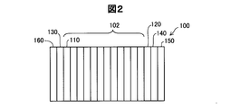
- FIG. 2 is an explanatory diagram showing a schematic configuration of the fuel cell 100.
- the fuel cell 100 includes a plurality of power generation cells 110, terminal plates 120 and 130, an insulating plate 140, and end plates 150 and 160.
- the plurality of power generation cells 110 are stacked to form the fuel cell stack 102.
- Terminal plates 120 and 130 are disposed at both ends of the fuel cell stack 102 in the stacking direction, respectively.
- the terminal plates 120 and 130 are used for extracting electric power from the fuel cell stack 102.
- An insulating plate 140 is disposed outside the terminal plate 120 in the stacking direction. There may be no insulating plate on the terminal plate 130 side.
- End plates 150 and 160 are disposed on the outer side of the insulating plate 140 in the stacking direction and on the outer side of the terminal plate 130 in the stacking direction, respectively.
- a part of the third fuel gas supply channel 220c and the fourth fuel gas supply channel 220d is arranged as a manifold. Therefore, in the present embodiment, the end plate 160 is also referred to as a stack manifold 160.
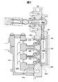
- FIG. 3 is an explanatory view showing a part of a cross section of the end plate 160.
- FIG. 3 shows a partial cross section of the end plate 160, and the contact portion with the terminal plate 130 (FIG. 2) is not shown.
- the end plate 160 is a plate-like member formed of a metal such as aluminum, and has a plurality of through holes 160h. The plurality of through holes 160h are used for attachment of the injector 270 or for passage of reaction gas.
- a fuel gas supply manifold 162 is attached to one surface 160 a of the end plate 160 so as to cover the injector 270.
- the fuel gas supply manifold 162 forms a part of a third fuel gas supply flow path 220 c that is a gas flow path on the upstream side of the injector 270.
- An end plate cover 164 is attached to the other surface 160 b of the end plate 160 so as to cover the outlet portion of the injector 270.
- the surface 160b is on the power generation cell 110 side and the terminal plate 130 side
- the surface 160a is on the side opposite to the power generation cell 110 (also referred to as “outside”).
- the end plate cover 164 is made of, for example, resin, and forms a part of the fourth fuel gas supply flow path 220d that is a gas flow path on the downstream side of the injector 270 with the end plate 160. .
- a mesh member 300 is disposed on the downstream side of the injection portion 270a of the injector 270.
- a fuel gas supply pipe 166 is provided so as to penetrate the end plate 160.
- the fuel gas supply pipe 166 forms the remaining part of the fourth fuel gas supply flow path 220d, and is connected to the fifth fuel gas supply flow path 220e and the fuel gas recirculation flow path 240 shown in FIG.
- the hydrogen pump 280 is attached to one surface 160a of the end plate 160.
- hydrogen is supplied to the injector 270 through the third fuel gas supply channel 220c (fuel gas supply manifold 162). Thereafter, the hydrogen is injected from the injection portion 270a of the injector 270 and is injected into the fourth fuel gas supply flow path 220d between the end plate cover 164 and the end plate 160. Hydrogen is sent to the outside of the end plate 160 from the fourth fuel gas supply flow path 220d between the end plate cover 164 and the end plate 160 through the fuel gas supply pipe 166. Outside the end plate 160, it joins with the reflux hydrogen sent from the hydrogen pump 280. After that, it is sent to the power generation cell 110 side of the end plate 160 through a pipe (not shown) and supplied to the power generation cell 110.
- FIG. 4 is an explanatory diagram showing an enlarged injection downstream portion of the injector 270.
- the injection part 270a of the injector 270 is inserted into the through hole 160h of the end plate 160 via a rubber ring 272.
- a mesh member 300 is disposed at the injection destination of the injector 270 in the through hole 160h.
- the mesh member 300 is a hollow tubular member having a substantially cylindrical shape, and includes a mesh 310 therein.
- the mesh member 300 reduces the pressure of the hydrogen injected from the injector 270 by the mesh 310. As a result, it is suppressed that a strong pressure is applied to the end plate cover 164 (FIG.
- An O-ring 320 is disposed on the outer edge of the mesh member 300. Even if vibration is generated in the mesh member 300 due to the pressure of the hydrogen injected from the injector 270, the O-ring 320 functions as a buffer member that reduces the vibration and does not transmit vibration to the end plate 160. Therefore, vibration of the end plate cover 164 and generation of noise accompanying the vibration can be suppressed.
- the O-ring 320 is preferably formed of a member having an excellent function of suppressing vibration, and is preferably formed of rubber, for example. As long as it has a function as a buffer member, another buffer member may be used instead of the O-ring 320.
- the gas supply apparatus of a claim has the structure containing the injector 270 and the mesh member 300. FIG.
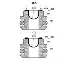
- FIG. 5 is a cross-sectional view of the mesh member.
- the upper diagram in FIG. 5 shows a state before the net 310 is caulked, and the lower diagram in FIG. 5 shows a state after the net 310 is caulked.
- the mesh member 300 includes a substantially cylindrical main body 330, a mesh 310, and an O-ring 320.
- the net 310 has a concave shape on the injector 270 side and a convex shape on the end plate cover 164 side.
- the end of the net 310 is attached to a protrusion 330 a provided on the side end of the main body 330. Thereafter, the projection 330 a is crushed to form the caulking portion 340, whereby the net 310 is fixed to the main body 330.
- the net 310 is housed inside the main body 330, and the net 310 is prevented from coming into contact with other members to be deformed or damaged.
- the net 310 may be fixed to the main body 330 by welding instead of being fixed to the main body 330 by the caulking portion 340.
- FIG. 6 is an example of a measurement result of vibration of the end plate cover 164 due to the pressure of hydrogen injected from the injector.
- the vibration is reduced by about 20 dB compared to the case where the mesh member 300 is not provided. That is, the vibration is reduced to about 1/10.
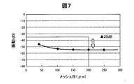
- FIG. 7 is an explanatory diagram showing the relationship between the mesh size of the mesh 310 of the mesh member 300 and the vibration of the end plate cover 164.
- the vibration of the end plate cover 164 was measured without using the mesh member 300, it was -35 dB.
- the vibration of the end plate cover 164 showed a minimum of about ⁇ 55 dB.
- the vibration of the end plate cover 164 gradually increased.
- the mesh size is in the range of 150 ⁇ m to 300 ⁇ m from the viewpoint of reducing vibration of the end plate cover 164. More preferably, the mesh size is in the range of 150 ⁇ m to 250 ⁇ m, and the mesh size may be 200 ⁇ m at which vibration is substantially minimized.
- FIG. 8 is an explanatory view showing an example of another shape of the mesh member 300.
- the net 310 is set inside the main body 330.
- the shape may protrude to the outside.
- the net 310 may be welded to the main body 330 as shown in FIG. 8A, or may be fixed by a caulking portion 340 as shown in FIG. 8B.
- the mesh member 300 functions as a pressure reducing member that reduces the pressure of hydrogen injected from the injector 270. Therefore, instead of the net member 300, for example, a member having a porous body, a slit, or a labyrinth structure may be used.
Landscapes
- Life Sciences & Earth Sciences (AREA)
- Engineering & Computer Science (AREA)
- Manufacturing & Machinery (AREA)
- Sustainable Development (AREA)
- Sustainable Energy (AREA)
- Chemical & Material Sciences (AREA)
- Chemical Kinetics & Catalysis (AREA)
- Electrochemistry (AREA)
- General Chemical & Material Sciences (AREA)
- Fuel Cell (AREA)
Abstract
インジェクターからのガス噴射に起因する振動、騒音の発生を抑制する。燃料電池用のガス供給装置は、燃料ガスを下流側のガス流路に噴射するインジェクターと、前記インジェクターと前記下流側のガス流路との間に配置され、前記インジェクターから噴射された前記燃料ガスの圧力を低減する圧力低減部材と、を備える。
Description
本発明は、燃料電池用のガス供給装置に関する。
燃料電池は、水素と、酸素とを反応させて発電を行う。水素は、燃料ガスタンクに貯蔵され、燃料ガス供給管により燃料電池に供給される。ガス供給管の途中にはインジェクターが設けられており、インジェクターを通して必要な量の水素が燃料電池のガス流路に噴射される。特許文献1に記載の燃料電池では、エンドプレートにインジェクターが配置され、インジェクターは、エンドプレートカバーに設けられたガス流路に水素を噴射する。
上述した従来技術では、インジェクターからの水素の噴射圧により、エンドプレートカバーが振動し、騒音が発生する虞があった。
本発明は、上述の課題の少なくとも一部を解決するためになされたものであり、以下の形態として実現することが可能である。
(1)本発明の一形態によれば、燃料電池用のガス供給装置が提供される。このガス供給装置は、燃料ガスを下流側のガス流路に噴射するインジェクターと、前記インジェクターと前記下流側のガス流路との間に配置され、前記インジェクターから噴射された前記燃料ガスの圧力を低減する圧力低減部材と、を備える。この形態のガス供給装置によれば、インジェクターから噴射された燃料ガスの圧力を圧力低減部材で低減することが出来るので、下流側のガス流路が燃料ガスの圧力によって振動することが発生し難くなり、騒音も発生し難くなる。
(2)上記形態のガス供給装置において、前記燃料電池は、複数の発電セルが積層された燃料電池スタックと、前記燃料電池スタックの積層方向の端に配置されたエンドプレートとを有し、前記インジェクターは、前記エンドプレートに設けられ、前記下流側のガス流路は、前記エンドプレート、または、前記エンドプレートに設けられたエンドプレートカバーに設けられていてもよい。この形態のガス供給装置によれば、エンドプレート、または、エンドプレートに設けられたエンドプレートカバーに設けられた下流側のガス流路の振動を低減することができる。
(3)上記形態のガス供給装置において、前記圧力低減部材は、中空の管であり、前記管の内部に網を有し、前記網のメッシュ目の粗さは、150μm~300μmであってもよい。この形態のガス供給装置によれば、網により、インジェクターから噴射された燃料ガスの圧力を低減できる。また、網は、管の内部にあるので、他の部材と接触して変形あるいは損傷し難い。また、メッシュ目の粗さは、150μm~300μmであると、下流側のガス流路の振動を低減の効果が大きい。
(4)上記形態のガス供給装置において、前記圧力低減部材は、前記エンドプレートに配置され、前記圧力低減部材と前記エンドプレートとの間に緩衝部材が設けられていてもよい。この形態のガス供給装置によれば、インジェクターからの噴射された燃料ガスの圧力により圧力低減部材に振動が生じても、緩衝部材により、エンドプレートへ振動が伝わりにくい。
なお、本発明は、種々の態様で実現することが可能である。例えば、燃料電池用のガス供給装置の他、ガス噴出装置、燃料電池システム等の形態で実現することができる。
図1は燃料電池システムの概略構成を示す説明図である。燃料電池システム10は、燃料電池100と、燃料ガス回路200と、酸化ガス回路と、冷却回路とを備える。燃料ガス回路200は、燃料タンク210と、燃料ガス供給流路220と、燃料ガス排気流路230と、燃料ガス還流流路240と、主止弁250と、調圧弁260と、インジェクター270と、水素ポンプ280と、排気弁290と、を備える。なお、図1では、酸化ガス回路と、冷却回路とは、図示を省略されている。なお、図1は、燃料ガス回路200のブロック構成を模式的に示した図であり、実際のレイアウトを示した図ではない。
燃料タンク210は、燃料ガスとして水素を貯蔵している。燃料タンク210は、燃料ガス供給流路220により燃料電池100に接続されている。燃料ガス供給流路220には、燃料タンク210側から、主止弁250、調圧弁260、インジェクター270が配置されている。燃料電池100には、燃料排ガスを大気に放出するための燃料ガス排気流路230が接続されている。燃料ガス排気流路230には、排気弁290が設けられている。燃料ガス供給流路220のインジェクター270の下流部と、燃料ガス排気流路230の排気弁290上流部との間は、燃料ガス還流流路240により接続されている。燃料ガス還流流路240には、水素ポンプ280が配置されている。本実施形態の燃料電池では、燃料排ガス中の水素を水素ポンプ280によって還流させて再利用する。燃料排ガス中に、例えば窒素等の不純物が増加した場合には、排気弁290が開けられて、燃料排ガスは、大気に放出される。
燃料ガス供給流路220は、便宜上、主止弁250と、調圧弁260と、インジェクター270と、燃料ガス還流流路240との接続部と、により5つの部分に分けることが可能である。燃料ガス供給流路220のうち、燃料タンク210から主止弁250間までを第1の燃料ガス供給流路220aと呼び、主止弁250から調圧弁260までを第2の燃料ガス供給流路220b、調圧弁260からインジェクター270までを第3の燃料ガス供給流路220c、インジェクター270から燃料ガス還流流路240との合流部までを第4の燃料ガス供給流路220d、燃料ガス還流流路240との合流部から燃料電池100までを第5の燃料ガス供給流路220eと呼ぶ。主止弁250は、燃料タンク210からの水素の供給をオン、オフする。調圧弁260は、第3の燃料ガス供給流路220cの圧力を所定の圧力に調整する。インジェクター270は、水素を下流側の第4の燃料ガス供給流路220dに噴射する。
図2は、燃料電池100の概略構成を示す説明図である。燃料電池100は、複数の発電セル110と、ターミナルプレート120、130と、絶縁プレート140と、エンドプレート150、160と、を備える。複数の発電セル110は、積層されて燃料電池スタック102を形成している。燃料電池スタック102の積層方向の両端には、それぞれターミナルプレート120、130が配置されている。ターミナルプレート120、130は、燃料電池スタック102から電力を取り出すために用いられる。ターミナルプレート120の積層方向の外側には、絶縁プレート140が配置されている。ターミナルプレート130側には、絶縁プレートは無くても良い。絶縁プレート140の積層方向の外側と、ターミナルプレート130の積層方向の外側には、それぞれ、エンドプレート150、160が配置されている。後述するように、エンドプレート160には、第3の燃料ガス供給流路220c、第4の燃料ガス供給流路220dの一部が、マニホールドとして配置されている。そのため、本実施形態では、エンドプレート160を、スタックマニホールド160とも呼ぶ。
図3は、エンドプレート160の断面の一部を示す説明図である。なお、図3は、エンドプレート160の一部の断面を示したもので有り、ターミナルプレート130(図2)との接触部は、図示されていない。エンドプレート160は、例えばアルミニウムなどの金属で形成された板状部材であり、複数の貫通孔160hを有している。複数の貫通孔160hは、インジェクター270の取り付け、あるいは、反応ガスの通過に用いられる。エンドプレート160の一方の面160aには、インジェクター270を覆うように燃料ガス供給マニホールド162が取り付けられている。燃料ガス供給マニホールド162は、インジェクター270の上流側のガス流路である第3の燃料ガス供給流路220cの一部を形成している。また、エンドプレート160の他方の面160bには、インジェクター270の出口部分を覆うように、エンドプレートカバー164が取り付けられている。本実施形態では、面160bが発電セル110側、ターミナルプレート130側であり、面160aが発電セル110と反対側(「外側」とも呼ぶ。)である。エンドプレートカバー164は、例えば樹脂で形成されており、エンドプレート160との間で、インジェクター270の下流側のガス流路である第4の燃料ガス供給流路220dの一部を形成している。なお、インジェクター270の断面構造の図示は省略している。インジェクター270の噴射部270aの下流側には、網状部材300が配置されている。また、エンドプレート160を貫通するように、燃料ガス供給管166が設けられている。燃料ガス供給管166は、第4の燃料ガス供給流路220dの残部を形成し、図1に示す第5の燃料ガス供給流路220e及び燃料ガス還流流路240に接続されている。なお、図示しないが、水素ポンプ280は、エンドプレート160の一方の面160aに取り付けられている。
図3において、水素は、第3の燃料ガス供給流路220c(燃料ガス供給マニホールド162)を通って、インジェクター270に供給される。その後、水素は、インジェクター270の噴射部270aから噴射され、エンドプレートカバー164とエンドプレート160との間の第4の燃料ガス供給流路220dに噴射される。水素は、エンドプレートカバー164とエンドプレート160の間の第4の燃料ガス供給流路220dから燃料ガス供給管166を通って、エンドプレート160の外側に送られる。エンドプレート160の外側では、水素ポンプ280から送られた還流水素と合流する。その後、図示しない配管を通ってエンドプレート160の発電セル110側に送られ、発電セル110に供給される。
図4は、インジェクター270の噴射下流部を拡大して示す説明図である。インジェクター270の噴射部270aは、ゴム製リング272を介してエンドプレート160の貫通孔160hに挿入されている。貫通孔160h中のインジェクター270の噴射先には、網状部材300が配置されている。網状部材300は、略円筒の形状を有する中空の管状の部材であり、内部に網310を備えている。網状部材300は、網310により、インジェクター270からの噴射された水素の圧力を低減する。その結果、エンドプレートカバー164(図3)に強い圧力が当たることが抑制され、エンドプレートカバー164の振動及び振動に伴う騒音の発生が抑制される。また、網状部材300の外縁部にはOリング320が配置されている。仮にインジェクター270から噴射された水素の圧力により網状部材300に振動が生じても、Oリング320は、その振動を緩和する緩衝部材として機能し、エンドプレート160に振動を伝達させない。そのため、エンドプレートカバー164の振動及び振動に伴う騒音の発生を抑制できる。Oリング320は、振動を抑制する機能に優れた部材で形成することが好ましく、例えばゴムで形成することが好ましい。緩衝部材としての機能を有していれば、Oリング320の代わりに他の緩衝部材を用いても良い。なお、請求項のガス供給装置は、インジェクター270と、網状部材300とを含む構成を有している。
図5は、網状部材の断面図である。図5の上図は、網310をかしめる前の状態を示し、図5の下図は、網310をかしめた後の状態を示している。網状部材300は、略円筒形の本体330と、網310と、Oリング320と、を備える。網310は、インジェクター270側が凹形、エンドプレートカバー164側が凸形となっている。網310の端部は、本体330の側端部に設けられている突起330aに取り付けられる。その後、突起330aがつぶされて、かしめ部340が形成されることにより、網310が本体330に固定される。本実施形態では、網310は本体330の内部に収まっており、網310が他の部材と接触して、変形あるいは損傷することを抑制している。なお、網310は、かしめ部340により本体330に固定される代わりに、溶接により本体330に固定されていても良い。
図6は、インジェクターから噴射された水素の圧力によるエンドプレートカバー164の振動の測定結果の一例である。測定周波数にもよるが、インジェクター270の下流側に網状部材300が設けられていると、網状部材300が設けられていない場合に比べて、約20dB振動が少なくなっている。すなわち振動は約1/10に小さくなっている。
図7は、網状部材300の網310のメッシュ目粗さと、エンドプレートカバー164の振動との関係を示す説明図である。網状部材300を用いない状態でエンドプレートカバー164の振動を測定すると、-35dBであった。網状部材300のメッシュ目の大きさを150μm~250μmの範囲とすると、エンドプレートカバー164の振動は、約-55dBと極小を示した。網状部材300のメッシュ目の大きさを150μmよりも細かくすると、エンドプレートカバー164の振動は徐々に大きくなった。この理由として、メッシュ目の大きさが小さくなると、インジェクター270から噴射された水素の圧力によって網状部材300自体が振動し、網状部材300の振動が網状部材300とエンドプレート160の結合部分を通してエンドプレート160に伝わるためと考えられる。したがって、メッシュ目の大きさが150μm~300μmの範囲であることが、エンドプレートカバー164の振動が小さくなる点で好ましい。メッシュ目の大きさが150μm~250μmの範囲であることがより好ましく、メッシュ目の大きさは、振動がほぼ極小となる200μmであってもよい。
図8は、網状部材300の他の形状の例を示す説明図である。本実施形態では、網310を本体330の内部に収まるようにした。しかし、網状部材300がエンドプレート160に取り付けられた後は、網310が他の部材と接触する可能性は低いため、図8(A)(B)に示すように、網310が本体330の外部にはみ出ていている形状であってもよい。網310は、図8(A)に示すように、本体330に、溶接されていても良く、図8(B)に示すように、かしめ部340により固定されていても良い。
本実施形態では、上述したように、網状部材300は、インジェクター270から噴射された水素の圧力を低減する圧力低減部材として機能する。したがって、網状部材300の代わりに、例えば、多孔体、スリットやラビリンス構造を有する部材を用いても良い。
以上、いくつかの実施例に基づいて本発明の実施の形態について説明してきたが、上記した発明の実施の形態は、本発明の理解を容易にするためのものであり、本発明を限定するものではない。本発明は、その趣旨並びに特許請求の範囲を逸脱することなく、変更、改良され得るとともに、本発明にはその等価物が含まれることはもちろんである。
10…燃料電池システム
100…燃料電池
102…燃料電池スタック
110…発電セル
120、130…ターミナルプレート
140…絶縁プレート
150…エンドプレート
160…エンドプレート(スタックマニホールド)
160a、160b…面
160h…貫通孔
162…燃料ガス供給マニホールド
164…エンドプレートカバー
166…燃料ガス供給管
200…燃料ガス回路
210…燃料タンク
220…燃料ガス供給流路
220a…第1の燃料ガス供給流路
220b…第2の燃料ガス供給流路
220c…第3の燃料ガス供給流路
220d…第4の燃料ガス供給流路
220e…第5の燃料ガス供給流路
230…燃料ガス排気流路
240…燃料ガス還流流路
250…主止弁
260…調圧弁
270…インジェクター
270a…噴射部
272…ゴム製リング
280…水素ポンプ
290…排気弁
300…網状部材
310…網
320…Oリング
330…本体
340…かしめ部
100…燃料電池
102…燃料電池スタック
110…発電セル
120、130…ターミナルプレート
140…絶縁プレート
150…エンドプレート
160…エンドプレート(スタックマニホールド)
160a、160b…面
160h…貫通孔
162…燃料ガス供給マニホールド
164…エンドプレートカバー
166…燃料ガス供給管
200…燃料ガス回路
210…燃料タンク
220…燃料ガス供給流路
220a…第1の燃料ガス供給流路
220b…第2の燃料ガス供給流路
220c…第3の燃料ガス供給流路
220d…第4の燃料ガス供給流路
220e…第5の燃料ガス供給流路
230…燃料ガス排気流路
240…燃料ガス還流流路
250…主止弁
260…調圧弁
270…インジェクター
270a…噴射部
272…ゴム製リング
280…水素ポンプ
290…排気弁
300…網状部材
310…網
320…Oリング
330…本体
340…かしめ部
Claims (4)
- 燃料電池用のガス供給装置であって、
燃料ガスを下流側のガス流路に噴射するインジェクターと、
前記インジェクターと前記下流側のガス流路との間に配置され、前記インジェクターから噴射された前記燃料ガスの圧力を低減する圧力低減部材と、
を備える、ガス供給装置。 - 請求項1に記載のガス供給装置において、
前記燃料電池は、複数の発電セルが積層された燃料電池スタックと、前記燃料電池スタックの積層方向の端に配置されたエンドプレートとを有し、
前記インジェクターは、前記エンドプレートに設けられ、
前記下流側のガス流路は、前記エンドプレート、または、前記エンドプレートに設けられたエンドプレートカバーに設けられている、ガス供給装置。 - 請求項2に記載のガス供給装置において、
前記圧力低減部材は、中空の管であり、前記管の内部に網を有し、
前記網のメッシュ目の粗さは、150μm~300μmである、ガス供給装置。 - 請求項2または3に記載のガス供給装置において、
前記圧力低減部材は、前記エンドプレートに配置され、
前記圧力低減部材と前記エンドプレートとの間に緩衝部材が設けられている、ガス供給装置。
Applications Claiming Priority (2)
| Application Number | Priority Date | Filing Date | Title |
|---|---|---|---|
| JP2013-228121 | 2013-11-01 | ||
| JP2013228121A JP2015088407A (ja) | 2013-11-01 | 2013-11-01 | 燃料電池用のガス供給装置 |
Publications (1)
| Publication Number | Publication Date |
|---|---|
| WO2015064005A1 true WO2015064005A1 (ja) | 2015-05-07 |
Family
ID=53003641
Family Applications (1)
| Application Number | Title | Priority Date | Filing Date |
|---|---|---|---|
| PCT/JP2014/004824 Ceased WO2015064005A1 (ja) | 2013-11-01 | 2014-09-19 | 燃料電池用のガス供給装置 |
Country Status (2)
| Country | Link |
|---|---|
| JP (1) | JP2015088407A (ja) |
| WO (1) | WO2015064005A1 (ja) |
Families Citing this family (1)
| Publication number | Priority date | Publication date | Assignee | Title |
|---|---|---|---|---|
| JP6493162B2 (ja) * | 2015-11-05 | 2019-04-03 | トヨタ自動車株式会社 | 燃料電池用水素供給装置 |
Citations (6)
| Publication number | Priority date | Publication date | Assignee | Title |
|---|---|---|---|---|
| JP2006083802A (ja) * | 2004-09-17 | 2006-03-30 | Denso Corp | 燃料噴射装置 |
| JP2008130446A (ja) * | 2006-11-22 | 2008-06-05 | Toyota Motor Corp | 燃料電池システム |
| JP2009129827A (ja) * | 2007-11-27 | 2009-06-11 | Toyota Motor Corp | 燃料電池システム |
| JP2010261317A (ja) * | 2009-04-30 | 2010-11-18 | Aisan Ind Co Ltd | インジェクタ |
| JP2012195176A (ja) * | 2011-03-17 | 2012-10-11 | Toyota Motor Corp | 燃料電池システム |
| US20120288780A1 (en) * | 2011-05-10 | 2012-11-15 | GM Global Technology Operations LLC | Acoustic speed of sound measurement using bandpass filtering of automotive pressure sensors |
-
2013
- 2013-11-01 JP JP2013228121A patent/JP2015088407A/ja not_active Withdrawn
-
2014
- 2014-09-19 WO PCT/JP2014/004824 patent/WO2015064005A1/ja not_active Ceased
Patent Citations (6)
| Publication number | Priority date | Publication date | Assignee | Title |
|---|---|---|---|---|
| JP2006083802A (ja) * | 2004-09-17 | 2006-03-30 | Denso Corp | 燃料噴射装置 |
| JP2008130446A (ja) * | 2006-11-22 | 2008-06-05 | Toyota Motor Corp | 燃料電池システム |
| JP2009129827A (ja) * | 2007-11-27 | 2009-06-11 | Toyota Motor Corp | 燃料電池システム |
| JP2010261317A (ja) * | 2009-04-30 | 2010-11-18 | Aisan Ind Co Ltd | インジェクタ |
| JP2012195176A (ja) * | 2011-03-17 | 2012-10-11 | Toyota Motor Corp | 燃料電池システム |
| US20120288780A1 (en) * | 2011-05-10 | 2012-11-15 | GM Global Technology Operations LLC | Acoustic speed of sound measurement using bandpass filtering of automotive pressure sensors |
Also Published As
| Publication number | Publication date |
|---|---|
| JP2015088407A (ja) | 2015-05-07 |
Similar Documents
| Publication | Publication Date | Title |
|---|---|---|
| CN105591144B (zh) | 燃料电池装置 | |
| JP2009070792A (ja) | 燃料電池スタックのガスケット | |
| JP2015088407A (ja) | 燃料電池用のガス供給装置 | |
| EP2922128B1 (en) | Fuel cell system | |
| JP5353558B2 (ja) | 燃料電池スタック | |
| WO2009084230A1 (ja) | 燃料電池 | |
| JP2013225411A (ja) | 燃料電池発電システム | |
| JP5624791B2 (ja) | 発電装置 | |
| US9711810B2 (en) | Exhaust drain valve for fuel cell | |
| CN101073173A (zh) | 燃料电池隔离器 | |
| CN101868878B (zh) | 燃料电池系统 | |
| JP5234257B2 (ja) | 燃料電池用シール構造 | |
| JP2019087384A (ja) | 燃料電池車における配管構造 | |
| JP6178979B2 (ja) | 燃料処理装置 | |
| JP5309554B2 (ja) | 燃料電池システム | |
| JP2017172437A (ja) | 排ガス発電ユニット | |
| JP2010108708A (ja) | 燃料電池 | |
| JP2015153614A (ja) | 燃料電池用セパレータ | |
| JP2008171587A (ja) | 燃料電池システム | |
| JP5413552B2 (ja) | 燃料電池用シール構造 | |
| JP6493162B2 (ja) | 燃料電池用水素供給装置 | |
| JPWO2025047928A5 (ja) | ||
| JP2011086565A (ja) | 燃料電池システム | |
| JP4634294B2 (ja) | フューエルデリバリパイプ | |
| JP2011003296A (ja) | 燃料電池用の配管の締結部構造 |
Legal Events
| Date | Code | Title | Description |
|---|---|---|---|
| 121 | Ep: the epo has been informed by wipo that ep was designated in this application |
Ref document number: 14857313 Country of ref document: EP Kind code of ref document: A1 |
|
| NENP | Non-entry into the national phase |
Ref country code: DE |
|
| 122 | Ep: pct application non-entry in european phase |
Ref document number: 14857313 Country of ref document: EP Kind code of ref document: A1 |