WO2015064003A1 - 車両用開閉体の制御装置、制御方法、及び該制御装置を備えた車両用開閉体 - Google Patents
車両用開閉体の制御装置、制御方法、及び該制御装置を備えた車両用開閉体 Download PDFInfo
- Publication number
- WO2015064003A1 WO2015064003A1 PCT/JP2014/004792 JP2014004792W WO2015064003A1 WO 2015064003 A1 WO2015064003 A1 WO 2015064003A1 JP 2014004792 W JP2014004792 W JP 2014004792W WO 2015064003 A1 WO2015064003 A1 WO 2015064003A1
- Authority
- WO
- WIPO (PCT)
- Prior art keywords
- voltage
- circuit
- motor
- short
- opening
- Prior art date
- Legal status (The legal status is an assumption and is not a legal conclusion. Google has not performed a legal analysis and makes no representation as to the accuracy of the status listed.)
- Ceased
Links
Images








Classifications
-
- H—ELECTRICITY
- H02—GENERATION; CONVERSION OR DISTRIBUTION OF ELECTRIC POWER
- H02H—EMERGENCY PROTECTIVE CIRCUIT ARRANGEMENTS
- H02H7/00—Emergency protective circuit arrangements specially adapted for specific types of electric machines or apparatus or for sectionalised protection of cable or line systems, and effecting automatic switching in the event of an undesired change from normal working conditions
- H02H7/08—Emergency protective circuit arrangements specially adapted for specific types of electric machines or apparatus or for sectionalised protection of cable or line systems, and effecting automatic switching in the event of an undesired change from normal working conditions for dynamo-electric motors
- H02H7/0833—Emergency protective circuit arrangements specially adapted for specific types of electric machines or apparatus or for sectionalised protection of cable or line systems, and effecting automatic switching in the event of an undesired change from normal working conditions for dynamo-electric motors for electric motors with control arrangements
- H02H7/0844—Fail safe control, e.g. by comparing control signal and controlled current, isolating motor on commutation error
-
- E—FIXED CONSTRUCTIONS
- E05—LOCKS; KEYS; WINDOW OR DOOR FITTINGS; SAFES
- E05F—DEVICES FOR MOVING WINGS INTO OPEN OR CLOSED POSITION; CHECKS FOR WINGS; WING FITTINGS NOT OTHERWISE PROVIDED FOR, CONCERNED WITH THE FUNCTIONING OF THE WING
- E05F15/00—Power-operated mechanisms for wings
- E05F15/60—Power-operated mechanisms for wings using electrical actuators
-
- H—ELECTRICITY
- H02—GENERATION; CONVERSION OR DISTRIBUTION OF ELECTRIC POWER
- H02P—CONTROL OR REGULATION OF ELECTRIC MOTORS, ELECTRIC GENERATORS OR DYNAMO-ELECTRIC CONVERTERS; CONTROLLING TRANSFORMERS, REACTORS OR CHOKE COILS
- H02P29/00—Arrangements for regulating or controlling electric motors, appropriate for both AC and DC motors
- H02P29/02—Providing protection against overload without automatic interruption of supply
- H02P29/024—Detecting a fault condition, e.g. short circuit, locked rotor, open circuit or loss of load
- H02P29/0241—Detecting a fault condition, e.g. short circuit, locked rotor, open circuit or loss of load the fault being an overvoltage
-
- H—ELECTRICITY
- H02—GENERATION; CONVERSION OR DISTRIBUTION OF ELECTRIC POWER
- H02P—CONTROL OR REGULATION OF ELECTRIC MOTORS, ELECTRIC GENERATORS OR DYNAMO-ELECTRIC CONVERTERS; CONTROLLING TRANSFORMERS, REACTORS OR CHOKE COILS
- H02P7/00—Arrangements for regulating or controlling the speed or torque of electric DC motors
- H02P7/06—Arrangements for regulating or controlling the speed or torque of electric DC motors for regulating or controlling an individual DC dynamo-electric motor by varying field or armature current
-
- H—ELECTRICITY
- H02—GENERATION; CONVERSION OR DISTRIBUTION OF ELECTRIC POWER
- H02P—CONTROL OR REGULATION OF ELECTRIC MOTORS, ELECTRIC GENERATORS OR DYNAMO-ELECTRIC CONVERTERS; CONTROLLING TRANSFORMERS, REACTORS OR CHOKE COILS
- H02P7/00—Arrangements for regulating or controlling the speed or torque of electric DC motors
- H02P7/06—Arrangements for regulating or controlling the speed or torque of electric DC motors for regulating or controlling an individual DC dynamo-electric motor by varying field or armature current
- H02P7/18—Arrangements for regulating or controlling the speed or torque of electric DC motors for regulating or controlling an individual DC dynamo-electric motor by varying field or armature current by master control with auxiliary power
- H02P7/24—Arrangements for regulating or controlling the speed or torque of electric DC motors for regulating or controlling an individual DC dynamo-electric motor by varying field or armature current by master control with auxiliary power using discharge tubes or semiconductor devices
- H02P7/28—Arrangements for regulating or controlling the speed or torque of electric DC motors for regulating or controlling an individual DC dynamo-electric motor by varying field or armature current by master control with auxiliary power using discharge tubes or semiconductor devices using semiconductor devices
- H02P7/285—Arrangements for regulating or controlling the speed or torque of electric DC motors for regulating or controlling an individual DC dynamo-electric motor by varying field or armature current by master control with auxiliary power using discharge tubes or semiconductor devices using semiconductor devices controlling armature supply only
- H02P7/29—Arrangements for regulating or controlling the speed or torque of electric DC motors for regulating or controlling an individual DC dynamo-electric motor by varying field or armature current by master control with auxiliary power using discharge tubes or semiconductor devices using semiconductor devices controlling armature supply only using pulse modulation
-
- E—FIXED CONSTRUCTIONS
- E05—LOCKS; KEYS; WINDOW OR DOOR FITTINGS; SAFES
- E05F—DEVICES FOR MOVING WINGS INTO OPEN OR CLOSED POSITION; CHECKS FOR WINGS; WING FITTINGS NOT OTHERWISE PROVIDED FOR, CONCERNED WITH THE FUNCTIONING OF THE WING
- E05F15/00—Power-operated mechanisms for wings
- E05F15/60—Power-operated mechanisms for wings using electrical actuators
- E05F15/603—Power-operated mechanisms for wings using electrical actuators using rotary electromotors
- E05F15/632—Power-operated mechanisms for wings using electrical actuators using rotary electromotors for horizontally-sliding wings
-
- E—FIXED CONSTRUCTIONS
- E05—LOCKS; KEYS; WINDOW OR DOOR FITTINGS; SAFES
- E05Y—INDEXING SCHEME ASSOCIATED WITH SUBCLASSES E05D AND E05F, RELATING TO CONSTRUCTION ELEMENTS, ELECTRIC CONTROL, POWER SUPPLY, POWER SIGNAL OR TRANSMISSION, USER INTERFACES, MOUNTING OR COUPLING, DETAILS, ACCESSORIES, AUXILIARY OPERATIONS NOT OTHERWISE PROVIDED FOR, APPLICATION THEREOF
- E05Y2400/00—Electronic control; Electrical power; Power supply; Power or signal transmission; User interfaces
- E05Y2400/10—Electronic control
- E05Y2400/30—Electronic control of motors
-
- E—FIXED CONSTRUCTIONS
- E05—LOCKS; KEYS; WINDOW OR DOOR FITTINGS; SAFES
- E05Y—INDEXING SCHEME ASSOCIATED WITH SUBCLASSES E05D AND E05F, RELATING TO CONSTRUCTION ELEMENTS, ELECTRIC CONTROL, POWER SUPPLY, POWER SIGNAL OR TRANSMISSION, USER INTERFACES, MOUNTING OR COUPLING, DETAILS, ACCESSORIES, AUXILIARY OPERATIONS NOT OTHERWISE PROVIDED FOR, APPLICATION THEREOF
- E05Y2400/00—Electronic control; Electrical power; Power supply; Power or signal transmission; User interfaces
- E05Y2400/10—Electronic control
- E05Y2400/50—Fault detection
- E05Y2400/504—Fault detection of control, of software
-
- E—FIXED CONSTRUCTIONS
- E05—LOCKS; KEYS; WINDOW OR DOOR FITTINGS; SAFES
- E05Y—INDEXING SCHEME ASSOCIATED WITH SUBCLASSES E05D AND E05F, RELATING TO CONSTRUCTION ELEMENTS, ELECTRIC CONTROL, POWER SUPPLY, POWER SIGNAL OR TRANSMISSION, USER INTERFACES, MOUNTING OR COUPLING, DETAILS, ACCESSORIES, AUXILIARY OPERATIONS NOT OTHERWISE PROVIDED FOR, APPLICATION THEREOF
- E05Y2400/00—Electronic control; Electrical power; Power supply; Power or signal transmission; User interfaces
- E05Y2400/65—Power or signal transmission
- E05Y2400/654—Power or signal transmission by electrical cables
-
- E—FIXED CONSTRUCTIONS
- E05—LOCKS; KEYS; WINDOW OR DOOR FITTINGS; SAFES
- E05Y—INDEXING SCHEME ASSOCIATED WITH SUBCLASSES E05D AND E05F, RELATING TO CONSTRUCTION ELEMENTS, ELECTRIC CONTROL, POWER SUPPLY, POWER SIGNAL OR TRANSMISSION, USER INTERFACES, MOUNTING OR COUPLING, DETAILS, ACCESSORIES, AUXILIARY OPERATIONS NOT OTHERWISE PROVIDED FOR, APPLICATION THEREOF
- E05Y2900/00—Application of doors, windows, wings or fittings thereof
- E05Y2900/50—Application of doors, windows, wings or fittings thereof for vehicles
- E05Y2900/53—Type of wing
- E05Y2900/531—Doors
Definitions
- the present invention relates to a control device and control method for a vehicle opening / closing body that realizes fail-safe control, and a vehicle opening / closing body including the control device.
- Patent Document 1 discloses a drive circuit 2 including an FET 3 for operating the motor 1, a pre-drive circuit 5, a CPU 4, a state detection circuit 6, and a pre-drive circuit state detection circuit 7 (see Patent Document 1). (See FIGS. 1 and 8).
- the drive circuit 2 performs PWM control of the motor by applying a PWM (Pulse Width Modulation) signal output from the CPU 4 to the gate terminal of the FET 3 via the pre-drive circuit 5.
- PWM Pulse Width Modulation
- the state detection circuit 6 measures the voltage at the drain terminal of the FET 3, and the pre-drive circuit state detection circuit 7 measures the voltage at the gate terminal input to the FET 3.
- the CPU 4 detects the failure of the transistors in the FET 3 and the predrive circuit 5.
- the drive circuit 2 disclosed in Patent Document 1 the drive circuit 2, the motor 1, the power source and the like are connected by wiring. Since these wirings are placed in an environment where there is a lot of stress due to temperature changes, vibration, moisture, load, etc. inside the vehicle, the wiring may be damaged due to deterioration of the insulating coating of the wiring, disconnection of the wiring connection, breakage of the wiring, etc. Can cause a short circuit. For the same reason, a short circuit between the wiring and the vehicle body having the ground potential may occur. Even when a short circuit occurs due to such a cause, the motor may malfunction. For example, if a short circuit occurs when the open / close body is open, the motor may malfunction and the open / close body may close unintentionally. However, the drive circuit 2 disclosed in Patent Document 1 does not include a short-circuit detection unit and a control unit that suppresses malfunction.
- the CPU 4 controls the power applied to the motor 1 by applying a PWM signal to the FET 3 of the pre-drive circuit 5.
- a PWM signal for example, when the wiring connecting the FET 3 and the motor 1 is short-circuited to the ground, a large electric power is applied to the motor 1.
- a malfunction may occur in which the opening / closing body opens or closes at high speed. Therefore, there is a demand for a vehicle opening / closing body that includes a control device that detects a short circuit and suppresses malfunctions when a short circuit occurs.
- the present invention has been made in view of such problems, and the object of the present invention is to detect the occurrence of a short circuit and to open and close it when a wiring connecting an amplifier circuit, an opening / closing drive device, a power supply, etc. is short-circuited.
- An object of the present invention is to provide a control device for a vehicle opening / closing body capable of suppressing a malfunction of the body.
- One aspect of the present invention is an input circuit that inputs a voltage signal indicating a drive voltage among a power supply voltage applied to one end of an opening / closing motor of a vehicle opening / closing body and a drive voltage applied to the other end;
- a short-circuit state determination unit that determines a short-circuit state when it is outside the predetermined range, and an output that outputs a control signal for reducing the voltage applied to the open / close motor when the short-circuit state is determined.
- a control device for a vehicle opening / closing body comprising a circuit.
- the vehicle state detection device provided by one aspect of the present invention detects the occurrence of a short circuit and suppresses the malfunction of the switch body when the wiring connecting the amplifier circuit, the switching drive device, the power supply, etc. is short-circuited. it can.
- 1 is a schematic side view of a vehicle according to an embodiment of the present invention. It is a schematic block diagram of the sliding door which concerns on one Embodiment of this invention. It is a schematic sectional drawing of the opening-and-closing drive device concerning one embodiment of the present invention.
- 1 is a block diagram of a control device for a vehicle opening / closing body according to an embodiment of the present invention. It is a figure which shows the circuit structure of the control apparatus which concerns on one Embodiment of this invention. It is a figure which shows the waveform of a PWM signal. It is a figure which shows the waveform of the PWM signal in case a duty ratio is large.
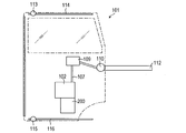
- FIG. 1 is a schematic side view of a vehicle 100 according to an embodiment of the present invention.
- the vehicle 100 includes a slide door 101 as a vehicle opening / closing body.
- the sliding door 101 includes an opening / closing mechanism driven by electric power, and is supported by the center rail 112, the upper rail 114, and the lower rail 116 so as to be movable in the front-rear direction of the vehicle 100 with respect to the vehicle body 100a.
- the vehicle opening / closing body is not limited to the sliding door 101 but may be the swing door 130 or the back door 140.
- FIG. 2A is a schematic configuration diagram of a slide door 101 as a vehicle opening / closing body
- FIG. 2B is a schematic sectional view of the opening / closing drive device 102.
- the configuration of the slide door 101 will be described in detail.
- the sliding door 101 is provided with an opening / closing drive device 102 and an ECU (Electronic Control Unit) 200.
- ECU 200 is not limited to the slide door 101 and can be attached to a desired location in the vehicle 100.
- the slide door 101 is supported by the center rail 112, the upper rail 114, and the lower rail 116 so as to be movable in the front-rear direction of the vehicle 100 via the center roller 110, the upper roller 113, and the lower roller 115, respectively.
- the ECU 200 controls the relay in the output circuit connected to the opening / closing drive device 102 to invert the polarity of the voltage applied to the opening / closing motor 102c. Thereby, the rotation direction of the opening / closing motor 102c is changed, and the opening / closing direction of the slide door 101 is controlled. Note that the user can manually open and close the slide door 101 in a state where the electromagnetic clutch 102b is not connected, that is, in a disconnected state.
- the pulse sensor 102a is a Hall element or the like, and outputs a pair of pulse signals having different phases to the ECU 200.
- the ECU 200 can detect the rotation amount, rotation speed, and rotation direction of the opening / closing motor 102c based on the pulse signal, and determine the position, movement speed, and movement direction of the slide door 101.
- the opening / closing drive device 102 includes a drive mechanism including a pulse sensor 102a, an electromagnetic clutch 102b, an opening / closing motor 102c, and a drum 102d.
- One end of the cable 107 is fixed to the drum 102d, and the other end of the cable 107 is guided to the guide pulley 109 and the center rail 112 and fixed to the vehicle body 100a. Therefore, the ECU 200 connects the electromagnetic clutch 102b, that is, puts the electromagnetic clutch 102b into a connected state, and drives the opening / closing motor 102c.
- the power of the opening / closing motor 102c is transmitted to the slide door 101 via the electromagnetic clutch 102b, the drum 102d, and the cable 107.
- the opening / closing drive device 102 can open / close the slide door 101 in accordance with the control signal output from the ECU 200.
- FIG. 3 is a block diagram of the ECU 200 or the like as a control device for the vehicle opening / closing body.
- the configuration of the ECU 200 as the control device for the vehicle opening / closing body will be described in detail.
- the ECU 200 includes a CPU (Central Processing Unit) 201, a memory 202, a control unit 203, an input circuit 205, an output circuit 207, and a system bus 210.
- the control unit 203 has a predetermined function for processing a signal input to the ECU 200 and controlling the opening / closing drive device 102 and the switch 304 in cooperation with the CPU 201 and the memory 202.
- the control unit 203 may be stored in the memory 202 as a software program describing functions executed by the CPU 201, or may be implemented in the ECU 200 as a hardware element.
- the ECU 200 may further include a hardware element such as an oscillator that provides a clock frequency to the CPU 201 and a counter circuit.
- the control unit 203 includes a short circuit state determination unit 204. Each component of the ECU 200 exchanges signals with each other via the system bus 210.
- the CPU 201 performs arithmetic processing for realizing a predetermined function
- the memory 202 includes a ROM (Read Only Memory) for storing a program, a RAM (Random Access Memory) for temporary storage, and the like.
- ROM Read Only Memory
- RAM Random Access Memory
- the input circuit 205 inputs a voltage signal (voltage signal indicating a driving voltage) from the opening / closing driving device 102 via the voltage dividing circuit 306.
- the input circuit 205 includes a voltage signal input unit 206.
- the voltage signal input unit 206 converts the input voltage signal into a digital signal that can be processed by the CPU 201.
- the voltage dividing circuit 306 divides the voltage signal from the opening / closing drive device 102 at a predetermined ratio, and converts the voltage signal into a voltage suitable for processing by the CPU 201 (for example, 0 to 5 V).
- the output circuit 207 includes a motor control signal output unit 208 and a cutoff signal output unit 209.
- the motor control signal output unit 208 converts the signal input via the system bus 210 into an analog signal, and outputs the analog signal as a control signal to the opening / closing drive device 102 via the amplifier circuit 307.
- the amplifier circuit 307 amplifies the control signal output from the motor control signal output unit 208 to a predetermined voltage (for example, 0 to 12 V) suitable for controlling the open / close motor 102c.
- the shut-off signal output unit 209 outputs a control signal for opening and closing the switch to the switch 304, and switches connection or opening between the opening / closing drive device 102 and the power source 305.
- the short-circuit state determination unit 204 determines whether the circuit in the open / close drive device 102 has short-circuited with the power supply or the switch based on the signal output from the open / close drive device 102.
- the control unit 203 outputs a control signal for controlling the open / close motor 102c and the switch 304 based on the determination result in the short-circuit state determination unit 204.
- the opening / closing motor 102c and the switch 304 perform predetermined operations.
- FIG. 4 shows a drive circuit 400 for a vehicle opening / closing body according to this embodiment.
- the drive circuit 400 includes an ECU 200 that is a control device for a vehicle opening / closing body, an opening / closing drive device 102, a switch 304, a power source 305, a voltage dividing circuit 306, and an amplifier circuit 307.
- the ECU 200 includes a voltage signal input unit 206, a motor control signal output unit 208, and a cutoff signal output unit 209.
- the amplifier circuit 307 is connected to the motor control output unit 208 of the ECU 200 through a wiring 432.
- the amplifier circuit 307, the open / close driving device 102, and the voltage dividing circuit 306 are connected to each other by a wiring 433.
- the voltage dividing circuit 306 is connected to the voltage signal input unit 206 of the ECU 200 through a wiring 434.
- Wirings 432, 433, 434 and the like are electric wirings used for power supply and transmission / reception of electric signals.
- “wiring” includes all electric wiring. For example, electric wires, connectors for connecting electric wires, fixtures such as clips, and wire harnesses and semiconductor elements configured by combining them And an electrode pattern on the printed circuit board.
- the motor control signal output unit 208 transmits a PWM signal for driving the vehicle opening / closing body to the amplifier circuit 307.
- the amplifier circuit 307 includes a predrive circuit 401 and an FET 402.
- the pre-drive circuit 401 is connected to the motor control signal output unit 208 of the ECU 200 by a wiring 432 and is connected to the FET 402 by a wiring 403.
- the pre-drive circuit 401 is a circuit that amplifies the PWM signal received from the ECU 200 and outputs it to the FET 402, and includes, for example, a transistor.
- the pre-drive circuit 401 is connected to a wiring 431 to which a power supply voltage is applied, and receives power necessary for amplification from the wiring 431.
- the FET 402 is an n-channel MOSFET (Metal-Oxide-Semiconductor Field Effect Transistor) and has a drain terminal 402a, a gate terminal 402b, and a source terminal 402c.
- the gate terminal 402b is connected to the pre-drive circuit 401 by the wiring 403, and receives the amplified PWM signal.
- the source terminal 402c is connected to the ground.
- the drain terminal 402 a is connected to the opening / closing drive device 102 and the input circuit 214 by a wiring 433. Further, a diode for protecting the FET 402 from the counter electromotive force of the open / close motor 102c is provided between the drain terminal 402a and the source terminal 402c.
- the voltage signal input unit 206 has a function of acquiring the voltage of the wiring 434 as an electric signal in order to detect a short circuit of the drive circuit 400. This function can be realized, for example, by converting the voltage of the wiring 434 into a digital signal by an A / D converter provided in the voltage signal input unit 206 and processing it.
- the voltage dividing circuit 306 includes a resistor 421 and a resistor 422. One end of the resistor 421 is connected to the amplifier circuit 307 and the open / close driving device 102 via the wiring 434, and the other end is connected to one end of the voltage signal input unit 206 and the resistor 422 via the wiring 434. The other end of the resistor 422 is connected to the ground.
- the opening / closing drive device 102 includes an opening / closing motor 102c and a resistor 412. One end of the open / close motor 102 c is connected to the resistor 412 through the wiring 413, and the other end is connected to the amplifier circuit 307 and the voltage dividing circuit 306 through the wiring 433. A power supply voltage is supplied to the resistor 412 through the wiring 431. When a voltage is supplied to the open / close motor 102c, power is supplied from the open / close motor 102c to the slide door 101 of the vehicle 100, and the slide door 101 opens or closes.
- the power supply 305 provided in the vehicle 100 is connected to the switch 304 via the wiring 435.
- the switch 304 is connected to the opening / closing drive device 102 via the wiring 431.
- the switch 304 is configured by, for example, an electromagnetic relay, an FET switch, or the like, and switches connection / disconnection between the wiring 435 and the wiring 431.
- a secondary battery such as a lead storage battery that supplies a DC voltage of about 12V is used.
- the PWM control will be described.
- An example of a PWM signal used for PWM control is shown in FIG. 5A.
- the PWM signal is a pulse signal that repeats a high voltage V H and a low voltage V L.
- Time to maintain the high voltage state is T H
- the time for maintaining the low voltage state is T L
- the parameters duty ratio (D T H / (T H + T L)) to determine the applied power. For example, if the power is applied to the load when the PWM signal is at the high voltage V H , the duty ratio of the PWM signal is increased as shown in FIG. The electric power to be increased.
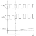
- FIG. 6 is a diagram illustrating the passage of time of the voltage (gate voltage) of the gate terminal 402b of the FET 402, the voltage (detection voltage) applied to the voltage signal input unit 206, and the rotation speed (motor rotation speed) of the open / close motor 102c.
- the electric power applied to the open / close motor 102c is PWM-controlled by the ECU 200 and the motor control signal output unit 208.
- the PWM signal output from the motor control signal output unit 208 is amplified by the pre-drive circuit 401 and applied to the gate terminal 402b.
- the PWM signal is a pulse signal that alternately repeats a high voltage and a low voltage at a predetermined duty ratio and cycle.
- the gate voltage is a pulse wave that alternately repeats the voltages V G0H and V G0L .
- FET402 is an n-channel type, when the gate voltage is V G0H, than when the V G0L, flows a large current from the drain terminal 402a toward the source terminal 402c. Therefore, the voltage (drain voltage) of the drain terminal 402a becomes a high voltage to a low voltage, the time of V G0L gate voltage at the time of V G0H. In this way, the pulse voltage generated by the PWM control is supplied to the open / close motor 102c connected to the drain terminal 402a via the wiring 433.
- the drain voltage divided by the voltage dividing circuit 306 is applied to the voltage signal input unit 206.
- the detection voltage has a waveform that is inverted (shifted by a half cycle) from the gate voltage as shown in the middle stage of FIG.
- the rotation speed of the open / close motor 102c can be stabilized.
- the motor rotation speed does not fluctuate due to a periodic change in voltage. That is, as shown in the lower part of FIG. 6, the motor rotational speed is a constant value.
- the drive circuit 400 has a plurality of wirings. These wirings are disposed in an environment where stress due to temperature change, vibration, moisture, load, etc. is great on the back side of the slide door 101 of the vehicle 100. For this reason, a short circuit between the wirings may occur due to deterioration of the insulating coating of the wirings, disconnection of the connection portions, breakage of the wirings, or the like. Further, due to the same cause, a short circuit between the wiring and a member having a ground potential such as the vehicle body 100a may occur.
- the detection voltage and the operation of the open / close motor 102c when the wirings 403, 413, 432, and 433 are short-circuited to the wiring having the power supply voltage or the ground will be described.
- a short circuit with a power supply potential or the like is expressed as “power supply and short circuit”
- a short circuit with a member such as the vehicle body 100a functioning as a ground wiring or ground is expressed as “ground and short circuit”.
- the opening / closing motor 102c is stopped, and the slide door 101 is also stopped in the open state or the closed state.
- the opening / closing motor 102 rotates, and the sliding door 101 is opened or closed. Since the open / close motor 102c includes a diode (not shown) for preventing back electromotive force, the motor does not reversely rotate even if a current flows in the reverse direction due to a short circuit.
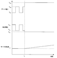
- Figure 7 shows the gate voltage when the wiring 413 is short-circuited to the power source and the time t 0, the time course of the detected voltage and motor speed.
- ⁇ Circuit operation when the wiring 433 is short-circuited to the power source shows a gate voltage when the wiring 433 is short-circuited to the power source and the time t 0, the time course of the detected voltage and motor speed.
- a short circuit occurs, a power supply voltage is applied to both ends of the open / close motor 102c. That is, the potential difference between both ends of the opening / closing motor 102c is zero. Therefore, as shown in the lower part of FIG. 9, the motor rotation speed remains zero, and the sliding door 101 does not malfunction.
- the detection voltage becomes a constant value (V D3H ) in the high voltage state as shown in the middle stage of FIG. 9, and the pulse by the PWM signal is not detected.
- Figure 10 shows the gate voltage when the wiring 433 is shorted to ground and the time t 0, the time course of the detected voltage and motor speed.
- the wiring 433 becomes the ground potential (0 V)
- the potential difference between both ends of the open / close motor 102c increases. Therefore, as shown in the lower part of FIG. 10, the motor rotation speed gradually increases as compared to before the occurrence of the short circuit. Therefore, a malfunction that the sliding door 101 opens or closes occurs. Further, the voltage of the wiring 433 becomes zero, and the detection voltage becomes zero as shown in the middle stage of FIG.
- Figure 11 shows the gate voltage when the wiring 403 is short-circuited to the power source and the time t 0, the time course of the detected voltage and motor speed.
- the wiring 403 has the same potential as the power source 431, and the gate voltage becomes a constant value V G5H that is higher than the high voltage side voltage V G0H before the short circuit as shown in the upper part of FIG.
- Figure 12 shows the gate voltage when the wiring 403 is shorted to ground and the time t 0, the time course of the detected voltage and motor speed.
- the wiring 403 becomes a ground potential, and the gate voltage becomes 0 V as shown in the upper part of FIG.
- the voltage applied to both ends of the open / close motor 102c becomes smaller than before the short circuit. Therefore, as shown in the lower part of FIG. 12, the motor rotation number remains zero, and the sliding door 101 does not malfunction.
- the detection voltage becomes constant at the high voltage V D0H as shown in the middle part of FIG. 11, and the pulse by the PWM signal is not detected.
- Figure 13 shows the gate voltage when the wiring 432 is short-circuited to the power source and the time t 0, the time course of the detected voltage and motor speed.
- the wiring 432 becomes the same potential as the power source 431, and the power source voltage is applied to the pre-drive circuit 401. That is, since the output of the pre-drive circuit is a high voltage and constant value than before short circuit, the gate voltage as shown in FIG. 13 upper part is constant at larger V G7H than the high voltage side voltage V G0H before shorting .
- Table 1 shows the occurrence status of a short circuit in each short circuit case, a change in gate voltage, a change in detection voltage, a change in motor rotation speed, and the propriety of PWM control after a short circuit.
- the short-circuit cases 1, 4, 5, and 7 in which the motor rotation speed increases, a malfunction that the sliding door 101 opens or closes occurs. Therefore, it is necessary not only to detect a short circuit but also to perform control for suppressing malfunction of the slide door 101 based on the detection result. Further, in the short-circuit cases 4, 5, and 7, the PWM control cannot be used for the control for reducing or stopping the sliding door 101.
- a detection method for the short-circuit cases 1, 4, 5, and 7 based on the detection voltage will be described. As shown in Table 1, the detection voltage increases in the short-circuit case 1, the detection voltage becomes zero in the short-circuit case 4, and the detection voltage decreases in the short-circuit cases 5 and 7. Further, in the short-circuit cases 4, 5 and 7, the detection voltage is a constant value, that is, the waveform of the PWM signal is not detected. That is, when it is detected that the detection voltage is rising but the PWM signal waveform is maintained, it is estimated that the short circuit case 1 may have occurred.
- the voltage to be measured is a pulse voltage at normal time or in the short-circuit case 1.
- voltage information used as a criterion for determination includes a high voltage V H , a low voltage V L , a simple average voltage ((V H + V L ) / 2), and a duty ratio. At least one of the weighted average voltages (DV H + (1 ⁇ D) V L ) by D can be selected and used.
- the threshold value for detecting a short circuit can be set so as to have good detection accuracy.
- FIG. 14 shows a flowchart of a control method for detecting the short-circuit cases 1, 4, 5 and 7 and suppressing the malfunction of the sliding door 101.
- step S1410 the ECU 200 measures the voltage input to the voltage signal input unit 206. Since the signal applied to the FET 402 is a PWM signal under normal conditions, the measured voltage is also a pulse voltage that repeats a high voltage and a low voltage. Therefore, not only the voltage value but also whether the measured voltage is a pulse voltage may be detected, and the information may be referred to in the subsequent steps.
- step S1420 ECU 200 causes short circuit state determination unit 204 to determine the short circuit state based on the voltage measured in step S1410.
- the detection voltage increases or decreases and falls outside the predetermined range, it is determined that at least one of the short-circuit cases 1, 4, 5, and 7 described above may have occurred, and the process proceeds to step S1430. Otherwise, the process returns to step S1410 and the voltage measurement is continued.
- step S1430 the ECU 200 transmits a control signal for switching off the switch 304 to shut off the power supplied to the motor in the shut-off signal output unit 209. By shutting off the electric power supplied to the opening / closing motor 102c, malfunction of the slide door 101 can be suppressed.
- the control device for a vehicle opening / closing body determines a short circuit of a circuit that controls the opening / closing motor, and stops the malfunction of the vehicle opening / closing body when it is determined that the circuit is in a short circuit state that may cause a malfunction. Can be made. Therefore, it is possible to prevent a malfunction in which the door opens unintentionally while the vehicle is traveling or stopped, and a malfunction in which the door closes unintentionally when the door is open.
- FIG. 1 A flowchart of a control method according to the modification is shown in FIG. This modification is characterized in that, when it is determined that a short circuit case 1 capable of PWM control has occurred, a step of performing control by PWM control is provided instead of step S1430. Steps S1410 and S1430 are substantially the same as the above-described flow, and a description thereof will be omitted.
- step S1510 ECU 200 causes short circuit state determination unit 204 to determine the short circuit state based on the voltage measured in step S1410. If the detected voltage increases and exceeds the predetermined range, it is determined that the above-described short-circuit case 1 may have occurred, and the process proceeds to step S1520. Otherwise, the process proceeds to step S1530.
- step S1420 ECU 200 causes short circuit state determination unit 204 to determine the short circuit state based on the voltage measured in step S1410.
- the detection voltage decreases and falls below the predetermined range, it is determined that at least one of the short-circuit cases 4, 5, and 7 described above may have occurred, and the process proceeds to step S1430. Otherwise, the process returns to step S1410 and the voltage measurement is continued.
- step S1520 the ECU 200 transmits a control signal for adjusting a parameter such as a duty ratio of the PWM signal in the motor control signal output unit 208.
- a parameter such as a duty ratio of the PWM signal in the motor control signal output unit 208.
- the control device for a vehicle opening / closing body when it is determined that a short-circuit case 1 capable of PWM control has occurred in a circuit for controlling the opening / closing motor, opens / closes the vehicle by PWM control instead of power interruption. The malfunction of the body can be stopped. Thereby, in the short circuit case 1, since electric power is not interrupted
- step S1520 step S1430 may be used in combination. By doing so, the malfunction of the vehicle opening / closing body can be stopped more reliably.
- a step of storing information indicating a short-circuit case in the memory 102 may be further provided.
- the person in charge of repair can obtain information on the short-circuited location, and the repair of the short-circuited location can be performed efficiently.
Landscapes
- Engineering & Computer Science (AREA)
- Power Engineering (AREA)
- Power-Operated Mechanisms For Wings (AREA)
- Control Of Electric Motors In General (AREA)
- Control Of Direct Current Motors (AREA)
Abstract
車両用開閉体の制御装置において、車両用開閉体の開閉モータの一端に印加される電源電圧と他端に印加される駆動電圧のうち、駆動電圧を示す電圧信号を入力する入力回路と、駆動電圧が所定範囲外である場合に、短絡状態であると判断する短絡状態判断部と、短絡状態であると判断された場合に、開閉モータに印加される電圧を減少させるための制御信号を出力する出力回路とを備える。
Description
本発明は、フェールセーフ制御を実現する車両用開閉体の制御装置、制御方法、及び該制御装置を備えた車両用開閉体に関するものである。
モータによって開閉動作を自動で行うことが可能な車両の開閉体が知られている。特許文献1には、モータ1を動作させるためのFET3、プリドライブ回路5、CPU4、状態検出回路6及びプリドライブ回路状態検出回路7を備えた駆動回路2が開示されている(特許文献1の図1及び図8を参照)。駆動回路2は、CPU4から出力したPWM(Pulse Width Modulation)信号を、プリドライブ回路5を介してFET3のゲート端子に印加することで、モータのPWM制御を行う。
状態検出回路6は、FET3のドレイン端子の電圧を測定し、プリドライブ回路状態検出回路7はFET3に入力するゲート端子の電圧を測定する。状態検出回路6で測定された電圧とプリドライブ回路状態検出回路7で測定された電圧とを比較することにより、CPU4はFET3及びプリドライブ回路5内のトランジスタの故障を検出する。このような故障検出機構を有する駆動回路2を車両用開閉体のモータに適用することにより、FET3及びプリドライブ回路5内のトランジスタの故障時に停止制御を行うことができ、操作者の意図に反する動作を防止できる。
特許文献1に開示された駆動回路2において、駆動回路2、モータ1、電源等は配線で接続されている。これらの配線は車両内部の温度変化、振動、湿気、荷重等によるストレスが大きい環境下に配設されるため、配線の絶縁被覆の劣化、配線接続部の離脱、配線の破断等によって、配線同士の短絡が発生し得る。また、同様の理由により配線とグランド電位を持つ車体との短絡も発生し得る。このような原因により短絡が発生した場合にも、モータが誤動作をする場合がある。例えば、開閉体が開状態のときに短絡が発生すると、モータが誤動作して意図に反して開閉体が閉動作する可能性がある。しかしながら、特許文献1に開示された駆動回路2は短絡の検出手段及び誤動作を抑制する制御手段を備えていない。
また、特許文献1では、CPU4はプリドライブ回路5のFET3にPWM信号を印加することで、モータ1への印加電力を制御している。この場合、例えばFET3とモータ1を接続する配線がグランドと短絡すると、大電力がモータ1に印加される。これにより、開閉体が高速に開動作又は閉動作する誤動作が起こる可能性もある。そのため、短絡発生時に、短絡を検出して誤動作を抑制する制御装置を備えた車両用開閉体が求められている。
本発明は、このような課題に鑑みてなされたもので、その目的とするところは、増幅回路、開閉駆動装置、電源等を接続する配線が短絡した際に、短絡の発生を検出し、開閉体の誤動作を抑制することができる車両用開閉体の制御装置を提供することにある。
本発明の一態様は、車両用開閉体の開閉モータの一端に印加される電源電圧と他端に印加される駆動電圧のうち、駆動電圧を示す電圧信号を入力する入力回路と、駆動電圧が所定範囲外である場合に、短絡状態であると判断する短絡状態判断部と、短絡状態であると判断された場合に、開閉モータに印加される電圧を減少させるための制御信号を出力する出力回路とを備える車両用開閉体の制御装置を提供する。
本発明の一態様により提供される車両用状態検出装置は増幅回路、開閉駆動装置、電源等を接続する配線が短絡した際に、短絡の発生を検出し、開閉体の誤動作を抑制することができる。
以下、本発明を実施するための例示的な実施形態を、図面を参照して詳細に説明する。ただし、以下の実施形態で説明する寸法、材料、形状、構成要素の相対的な位置等は任意であり、本発明が適用される装置の構造又は様々な条件に応じて変更できる。また、特別な記載がない限り、本発明の範囲は、以下に説明される実施形態で具体的に記載された形態に限定されるものではない。なお、以下で説明する図面で、同機能を有するものは同一符号を付け、その繰り返しの説明は省略することもある。
<車両の構成>
図1は、本発明の一実施形態に係る車両100の概略側面図である。車両100は、車両用開閉体としてのスライドドア101を備える。スライドドア101は、電力により駆動される開閉機構を備え、センターレール112、アッパーレール114及びロアレール116により、車両ボデー100aに対して車両100の前後方向に移動自在に支持されている。車両用開閉体は、スライドドア101に限らず、スイングドア130又はバックドア140であってもよい。
図1は、本発明の一実施形態に係る車両100の概略側面図である。車両100は、車両用開閉体としてのスライドドア101を備える。スライドドア101は、電力により駆動される開閉機構を備え、センターレール112、アッパーレール114及びロアレール116により、車両ボデー100aに対して車両100の前後方向に移動自在に支持されている。車両用開閉体は、スライドドア101に限らず、スイングドア130又はバックドア140であってもよい。
<車両用開閉体の構成>
図2Aは、車両用開閉体としてのスライドドア101の概略構成図であり、図2Bは、開閉駆動装置102の概略断面図である。以下、スライドドア101の構成について詳細に説明する。
図2Aは、車両用開閉体としてのスライドドア101の概略構成図であり、図2Bは、開閉駆動装置102の概略断面図である。以下、スライドドア101の構成について詳細に説明する。
スライドドア101には、開閉駆動装置102及び、ECU(Electronic Control Unit)200が取り付けられている。なお、ECU200は、スライドドア101に限らず、車両100内の所望の場所に取り付けられ得る。
スライドドア101は、センターレール112、アッパーレール114及びロアレール116に、それぞれセンターローラ110、アッパーローラ113及びロアローラ115を介して車両100の前後方向に移動自在に支持されている。
ECU200は、開閉駆動装置102に接続された出力回路内のリレーを制御することにより、開閉モータ102cに印加される電圧の極性を反転させる。これにより、開閉モータ102cの回転方向が変更され、スライドドア101の開閉方向が制御される。なお、電磁クラッチ102bがつながっていない状態、すなわち非接続状態では、ユーザは、スライドドア101を手動で開閉することができる。
パルスセンサ102aは、ホール素子等であり、互いに位相の異なる対のパルス信号をECU200に出力する。ECU200は、該パルス信号に基づいて、開閉モータ102cの回転量、回転速度及び回転方向を検出し、スライドドア101の位置、移動速度及び移動方向を判断することができる。
図2Bに示すように、開閉駆動装置102は、パルスセンサ102a、電磁クラッチ102b、開閉モータ102c及びドラム102dを含む駆動機構を備える。ケーブル107の一端がドラム102dに固定され、ケーブル107の他端がガイドプーリ109及びセンターレール112にガイドされて車両ボデー100aに固定されている。このため、ECU200が、電磁クラッチ102bをつなぎ、すなわち電磁クラッチ102bを接続状態にし、開閉モータ102cを駆動させる。これにより、開閉モータ102cの動力が、電磁クラッチ102b、ドラム102d及びケーブル107を介してスライドドア101に伝わる。このように、開閉駆動装置102は、ECU200から出力された制御信号に応じて、スライドドア101を開閉駆動することができる。
<車両用開閉体の制御装置の構成>
図3は、車両用開閉体の制御装置としてのECU200等のブロック図である。以下、車両用開閉体の制御装置としてのECU200の構成について詳細に説明する。
図3は、車両用開閉体の制御装置としてのECU200等のブロック図である。以下、車両用開閉体の制御装置としてのECU200の構成について詳細に説明する。
ECU200は、CPU(Central Processing Unit)201、メモリ202、制御部203、入力回路205、出力回路207及びシステムバス210を備える。制御部203は、CPU201やメモリ202と協働して、ECU200に入力された信号を処理し、開閉駆動装置102及びスイッチ304を制御するための所定の機能を備える。なお、制御部203は、CPU201により実行される機能を記したソフトウェアプログラムとしてメモリ202内に記憶されていてもよいし、ハードウェア素子としてECU200内に実装されていてもよい。また、ECU200は、CPU201にクロック周波数を提供する発振器や、カウンタ回路等のハードウェア素子をさらに備えていてもよい。
制御部203は、短絡状態判断部204を含む。ECU200の各構成要素は、システムバス210を介して互いに信号のやりとりを行う。
CPU201は、所定の機能を実現するための演算処理を行い、メモリ202は、プログラムを記憶するためのROM(Read Only Memory)や、一時記憶のためのRAM(Random Access Memory)等を備える。
入力回路205は、開閉駆動装置102からの電圧信号(駆動電圧を示す電圧信号)を分圧回路306を介して入力する。入力回路205は、電圧信号入力部206を備える。電圧信号入力部206は入力した電圧信号をCPU201で処理可能なデジタル信号に変換する。分圧回路306は開閉駆動装置102からの電圧信号を所定の比率で分圧して、CPU201での処理に適した電圧(例えば0~5V)に変換する。
出力回路207は、モータ制御信号出力部208及び遮断信号出力部209を備える。モータ制御信号出力部208は、システムバス210を介して入力した信号をアナログ信号に変換し、増幅回路307を介して開閉駆動装置102に制御信号として出力する。増幅回路307はモータ制御信号出力部208から出力された制御信号を開閉モータ102cの制御に適した所定の電圧(例えば0~12V)に増幅する。遮断信号出力部209は、スイッチ304にスイッチの開閉のための制御信号を出力し、開閉駆動装置102と電源305の間の接続又は開放を切り替える。
短絡状態判断部204は、開閉駆動装置102から出力された信号に基づき、開閉駆動装置102内の回路が電源又はスイッチと短絡を起こしていないかどうかを判断する。
制御部203は、短絡状態判断部204での判断結果を基に開閉モータ102c及びスイッチ304を制御するための制御信号を、それぞれに向けて出力する。ECU200から出力された制御信号に応じて、開閉モータ102c及びスイッチ304は所定の動作を行う。
<車両用開閉体の駆動回路構成>
図4に本実施形態の車両用開閉体の駆動回路400を示す。車両用開閉体の駆動に係る回路構成を、図4を用いて説明する。駆動回路400は車両用開閉体の制御装置であるECU200、開閉駆動装置102、スイッチ304、電源305、分圧回路306及び増幅回路307を含む。
図4に本実施形態の車両用開閉体の駆動回路400を示す。車両用開閉体の駆動に係る回路構成を、図4を用いて説明する。駆動回路400は車両用開閉体の制御装置であるECU200、開閉駆動装置102、スイッチ304、電源305、分圧回路306及び増幅回路307を含む。
ECU200は電圧信号入力部206、モータ制御信号出力部208及び遮断信号出力部209を備える。増幅回路307は配線432によりECU200のモータ制御出力部208に接続される。増幅回路307と、開閉駆動装置102と、分圧回路306とは配線433によりそれぞれ相互に接続される。分圧回路306は配線434によりECU200の電圧信号入力部206に接続される。配線432、433、434等は電源供給及び電気信号の送受信に用いる電気配線である。なお、本明細書において、「配線」は電気配線すべてを含むものであり、一例としては、電線、電線を接続するコネクタ、クリップ等の固定具及びこれらを複合して構成したワイヤハーネス並びに半導体素子及びプリント基板上の電極パターンを含む。
モータ制御信号出力部208は増幅回路307に車両用開閉体を駆動するためのPWM信号を送信する。増幅回路307はプリドライブ回路401及びFET402を備える。プリドライブ回路401は配線432によりECU200のモータ制御信号出力部208と接続されており、配線403により、FET402と接続されている。プリドライブ回路401はECU200から受信したPWM信号を増幅してFET402に出力する回路であり、例えばトランジスタ等を含む。プリドライブ回路401は電源電圧が印加される配線431と接続され、配線431から増幅に必要な電力の供給を受ける。FET402はnチャネル型のMOSFET(Metal-Oxide-Semiconductor Field Effect Transistor)であり、ドレイン端子402a、ゲート端子402b及びソース端子402cを有する。ゲート端子402bは配線403によりプリドライブ回路401と接続され、増幅されたPWM信号を受信する。ソース端子402cはグランドに接続されている。ドレイン端子402aは配線433により開閉駆動装置102及び入力回路214と接続されている。また、ドレイン端子402a、ソース端子402c間には、開閉モータ102cの逆起電力からFET402を保護するためのダイオードが設けられている。
電圧信号入力部206は駆動回路400の短絡を検出するため、配線434の電圧を電気信号として取得する機能を有する。この機能は例えば、電圧信号入力部206内に備えられたA/Dコンバータにより配線434の電圧をデジタル信号に変換して処理することにより実現できる。
分圧回路306は抵抗421及び抵抗422を備える。抵抗421の一端は配線434を介して増幅回路307及び開閉駆動装置102と接続され、他端は配線434を介して電圧信号入力部206及び抵抗422の一端と接続される。抵抗422の他端はグランドと接続される。配線433の電圧をV433、抵抗421の抵抗値をR421、抵抗422の抵抗値をR422とすると、配線434の電圧V434は、V434=V433・R422/(R411+R422)となる。したがって、配線434の電圧は分圧回路306によって所定の比率で分圧されてから電圧信号入力部206に印加される。例えば配線433に印加され得る最大電圧が12Vで、電圧信号入力部206に入力可能な最大電圧が5Vである場合、R422/(R411+R422)=5/12以下となるようにR421及びR422の値を選択する。そうすることで、電圧信号入力部206に入力される電圧が最大電圧を超えることによる誤測定等の問題が抑制される。
開閉駆動装置102は、開閉モータ102cと、抵抗412とを備える。開閉モータ102cの一端は配線413を介して抵抗412と接続され、他端は配線433を介して増幅回路307及び分圧回路306と接続される。抵抗412には配線431を介して電源電圧が供給される。開閉モータ102cに電圧が供給されると、開閉モータ102cから車両100のスライドドア101に動力が供給され、スライドドア101は開動作又は閉動作する。
車両100に備えられた電源305は配線435を介してスイッチ304と接続される。スイッチ304は配線431を介して開閉駆動装置102と接続される。スイッチ304は例えば電磁リレー、FETスイッチ等で構成され、配線435と配線431の間の接続、非接続を切り替える。スイッチ304が閉の場合、開閉モータ102cに電力が供給され、開の場合、電力は供給されない。スイッチ304の切り替えはECU200の遮断信号出力部209から配線436を介して受信した信号によって行われる。電源305には、例えば12V程度のDC電圧を供給する鉛蓄電池等の2次電池が用いられる。
<車両用開閉体の回路動作>
PWM制御について説明する。PWM制御に用いられるPWM信号の例を図5Aに示す。PWM信号は高電圧VH、低電圧VLを繰り返すパルス信号である。高電圧状態を維持する時間がTH、低電圧状態を維持する時間がTLのとき、デューティー比(D=TH/(TH+TL))が印加電力を決定するパラメータとなる。例えば、PWM信号が高電圧VHのとき負荷に電力が印加されるとすると、図5Bに示すようにPWM信号のデューティー比を大きくすると、電力が印加される時間割合が増加するので負荷に印加される電力は大きくなる。すなわち、電圧値を変化させなくてもデューティー比を変化させることにより、電力が供給される時間の割合を調整して、供給電力を連続的に変化させることができる。CPUの出力はデジタル信号であるため、電圧を連続的に変化させることよりもパルス信号のON/OFFを調整することの方が容易である。そのため、PWM制御は回転数の制御を要するモータの電力制御等に用いられる。
PWM制御について説明する。PWM制御に用いられるPWM信号の例を図5Aに示す。PWM信号は高電圧VH、低電圧VLを繰り返すパルス信号である。高電圧状態を維持する時間がTH、低電圧状態を維持する時間がTLのとき、デューティー比(D=TH/(TH+TL))が印加電力を決定するパラメータとなる。例えば、PWM信号が高電圧VHのとき負荷に電力が印加されるとすると、図5Bに示すようにPWM信号のデューティー比を大きくすると、電力が印加される時間割合が増加するので負荷に印加される電力は大きくなる。すなわち、電圧値を変化させなくてもデューティー比を変化させることにより、電力が供給される時間の割合を調整して、供給電力を連続的に変化させることができる。CPUの出力はデジタル信号であるため、電圧を連続的に変化させることよりもパルス信号のON/OFFを調整することの方が容易である。そのため、PWM制御は回転数の制御を要するモータの電力制御等に用いられる。
駆動回路400の動作について説明する。図6はFET402のゲート端子402bの電圧(ゲート電圧)、電圧信号入力部206に印加される電圧(検出電圧)、及び開閉モータ102cの回転数(モータ回転数)の時間経過を示す図である。上述の通り、開閉モータ102cに印加する電力はECU200及びモータ制御信号出力部208によってPWM制御される。モータ制御信号出力部208から出力されたPWM信号は、プリドライブ回路401で増幅され、ゲート端子402bに印加される。PWM信号は所定のデューティー比及び周期で高電圧と低電圧を交互に繰り返すパルス信号である。そのため、図6の上段に示すように、ゲート電圧は電圧VG0HとVG0Lを交互に繰り返すパルス波となる。本実施例ではFET402はnチャネル型であるため、ゲート電圧がVG0Hのときに、VG0Lのときよりも、ドレイン端子402aからソース端子402cに向かって多くの電流が流れる。したがって、ドレイン端子402aの電圧(ドレイン電圧)はゲート電圧がVG0Hの時刻に低電圧、VG0Lの時刻に高電圧となる。このようにして、配線433を介してドレイン端子402aと接続された開閉モータ102cにはPWM制御により生成されたパルス電圧が供給される。
このとき、電圧信号入力部206には分圧回路306によって分圧されたドレイン電圧が印加される。上述の通り、FET402のゲート電圧とドレイン電圧は反転するので、検出電圧は図5の中段のようにゲート電圧と反転した(半周期ずれた)波形となる。
PWM信号の周期を開閉モータ102cの時定数に比べて十分に小さくすると、開閉モータ102cの回転数を安定化することができる。この場合、モータ回転数は電圧の周期的変化によって揺らぐことはない。すなわち、図6下段に示すようにモータ回転数は一定値となる。
上述の通り、駆動回路400は複数の配線を有する。これらの配線は車両100のスライドドア101の裏側等の温度変化、振動、湿気、荷重等によるストレスが大きい環境下に配設される。そのため、配線の絶縁被覆の劣化や、接続部の離脱、配線の破断等の原因によって、配線同士の短絡が発生し得る。さらに同様の原因により、配線と車両ボデー100a等のグランド電位を持つ部材との短絡も発生し得る。このような原因により、配線403、413、432、433が電源電圧を持つ配線やグランドと短絡した場合の、検出電圧及び開閉モータ102cの動作について述べる。以下、電源電位を持つ配線等との短絡を「電源と短絡」、グランド配線やグランドとして機能する車両ボデー100a等の部材との短絡を「グランドと短絡」のように表記する。なお、初期状態において、開閉モータ102cは停止し、また、スライドドア101も開状態又は閉状態で停止している。電流が配線413から433に向かって流れると開閉モータ102は回転し、スライドドア101の開動作又は閉動作が行われる。開閉モータ102cは逆起電力防止用ダイオード(不図示)を備えているため、短絡により電流が逆向きに流れてもモータの逆回転は起こらない。
<配線413が電源と短絡した場合の回路動作(短絡ケース1)>
図7に、配線413が電源と時刻t0に短絡した場合のゲート電圧、検出電圧及びモータ回転数の時間経過を示す。短絡が発生すると配線413が電源と同電位となり、抵抗412による電圧降下が無くなるため、開閉モータ102cに印加される電圧は大きくなる。よって、図6下段に示すようにモータ回転数は短絡発生前に比べて徐々に上昇する。したがって、スライドドア101が開動作又は閉動作する誤動作が発生する。また、配線413の電圧が大きくなるため、図6中段に示すように、検出電圧はPWM制御によるパルス波形を維持しつつ上昇する。
図7に、配線413が電源と時刻t0に短絡した場合のゲート電圧、検出電圧及びモータ回転数の時間経過を示す。短絡が発生すると配線413が電源と同電位となり、抵抗412による電圧降下が無くなるため、開閉モータ102cに印加される電圧は大きくなる。よって、図6下段に示すようにモータ回転数は短絡発生前に比べて徐々に上昇する。したがって、スライドドア101が開動作又は閉動作する誤動作が発生する。また、配線413の電圧が大きくなるため、図6中段に示すように、検出電圧はPWM制御によるパルス波形を維持しつつ上昇する。
<配線413がグランドと短絡した場合の回路動作(短絡ケース2)>
図8に、配線413がグランドと時刻t0に短絡した場合のゲート電圧、検出電圧及びモータ回転数の時間経過を示す。短絡が発生すると配線413がグランド電位(0V)となり、開閉モータ102cには電圧が印加されない。よって、図8下段に示すようにモータ回転数はゼロのままであり、スライドドア101は誤動作しない。また、電圧の供給が無くなるため、検出電圧は図8中段に示すようにゼロとなる。
図8に、配線413がグランドと時刻t0に短絡した場合のゲート電圧、検出電圧及びモータ回転数の時間経過を示す。短絡が発生すると配線413がグランド電位(0V)となり、開閉モータ102cには電圧が印加されない。よって、図8下段に示すようにモータ回転数はゼロのままであり、スライドドア101は誤動作しない。また、電圧の供給が無くなるため、検出電圧は図8中段に示すようにゼロとなる。
<配線433が電源と短絡した場合の回路動作(短絡ケース3)>
図9に、配線433が電源と時刻t0に短絡した場合のゲート電圧、検出電圧及びモータ回転数の時間経過を示す。短絡が発生すると開閉モータ102cの両端にはいずれも電源電圧が印加される。すなわち、開閉モータ102cの両端の電位差はゼロである。よって、図9下段に示すようにモータ回転数はゼロのままであり、スライドドア101は誤動作しない。また、配線433に直接電源電圧が供給されるため、検出電圧は図9中段に示すように高電圧状態で一定値(VD3H)となり、PWM信号によるパルスは検出されない。
図9に、配線433が電源と時刻t0に短絡した場合のゲート電圧、検出電圧及びモータ回転数の時間経過を示す。短絡が発生すると開閉モータ102cの両端にはいずれも電源電圧が印加される。すなわち、開閉モータ102cの両端の電位差はゼロである。よって、図9下段に示すようにモータ回転数はゼロのままであり、スライドドア101は誤動作しない。また、配線433に直接電源電圧が供給されるため、検出電圧は図9中段に示すように高電圧状態で一定値(VD3H)となり、PWM信号によるパルスは検出されない。
<配線433がグランドと短絡した場合の回路動作(短絡ケース4)>
図10に、配線433がグランドと時刻t0に短絡した場合のゲート電圧、検出電圧及びモータ回転数の時間経過を示す。短絡が発生すると配線433がグランド電位(0V)となり、開閉モータ102cの両端の電位差が大きくなる。よって、図10下段に示すようにモータ回転数は短絡発生前に比べて徐々に上昇する。したがって、スライドドア101が開動作又は閉動作する誤動作が発生する。また、配線433の電圧はゼロになり、検出電圧も図10中段に示すようにゼロとなる。なお、このケースでは、PWM制御ができず、開閉モータ102cに常時電力が供給されるようになるため、短絡ケース1の場合よりも、開閉モータ102cの回転数の上昇が急激であり、スライドドア101の開動作又は閉動作も高速である。
図10に、配線433がグランドと時刻t0に短絡した場合のゲート電圧、検出電圧及びモータ回転数の時間経過を示す。短絡が発生すると配線433がグランド電位(0V)となり、開閉モータ102cの両端の電位差が大きくなる。よって、図10下段に示すようにモータ回転数は短絡発生前に比べて徐々に上昇する。したがって、スライドドア101が開動作又は閉動作する誤動作が発生する。また、配線433の電圧はゼロになり、検出電圧も図10中段に示すようにゼロとなる。なお、このケースでは、PWM制御ができず、開閉モータ102cに常時電力が供給されるようになるため、短絡ケース1の場合よりも、開閉モータ102cの回転数の上昇が急激であり、スライドドア101の開動作又は閉動作も高速である。
<配線403が電源と短絡した場合の回路動作(短絡ケース5)>
図11に、配線403が電源と時刻t0に短絡した場合のゲート電圧、検出電圧及びモータ回転数の時間経過を示す。短絡が発生すると配線403が電源431と同電位となり、図10上段に示すようにゲート電圧は短絡前の高電圧側電圧VG0Hよりも大きいVG5Hで一定値となる。このとき、FET402のゲート端子402bには常に高電圧が印加され続けるので、ドレイン端子402aからソース端子402cに向かって電流が流れ続け、開閉モータ102cの両端には常に一定の高電圧がかかる。よって、図11下段に示すようにモータ回転数は短絡発生前に比べて徐々に上昇する。したがって、スライドドア101が開動作又は閉動作する誤動作が発生する。また、配線433の電圧は低電圧のままになるため検出電圧は図11中段に示すように低電圧VD5Lで一定となり、PWM信号によるパルスは検出されない。
図11に、配線403が電源と時刻t0に短絡した場合のゲート電圧、検出電圧及びモータ回転数の時間経過を示す。短絡が発生すると配線403が電源431と同電位となり、図10上段に示すようにゲート電圧は短絡前の高電圧側電圧VG0Hよりも大きいVG5Hで一定値となる。このとき、FET402のゲート端子402bには常に高電圧が印加され続けるので、ドレイン端子402aからソース端子402cに向かって電流が流れ続け、開閉モータ102cの両端には常に一定の高電圧がかかる。よって、図11下段に示すようにモータ回転数は短絡発生前に比べて徐々に上昇する。したがって、スライドドア101が開動作又は閉動作する誤動作が発生する。また、配線433の電圧は低電圧のままになるため検出電圧は図11中段に示すように低電圧VD5Lで一定となり、PWM信号によるパルスは検出されない。
<配線403がグランドと短絡した場合の回路動作(短絡ケース6)>
図12に、配線403がグランドと時刻t0に短絡した場合のゲート電圧、検出電圧及びモータ回転数の時間経過を示す。短絡が発生すると配線403がグランド電位となり、図12上段に示すようにゲート電圧は0Vとなる。このとき、ドレイン端子402aからソース端子402cには電流が流れなくなるので、開閉モータ102cの両端にかかる電圧は短絡前よりも小さくなる。よって、図12下段に示すようにモータ回転数はゼロのままであり、スライドドア101は誤動作しない。また、検出電圧は図11中段に示すように高電圧VD0Hで一定となり、PWM信号によるパルスは検出されない。
図12に、配線403がグランドと時刻t0に短絡した場合のゲート電圧、検出電圧及びモータ回転数の時間経過を示す。短絡が発生すると配線403がグランド電位となり、図12上段に示すようにゲート電圧は0Vとなる。このとき、ドレイン端子402aからソース端子402cには電流が流れなくなるので、開閉モータ102cの両端にかかる電圧は短絡前よりも小さくなる。よって、図12下段に示すようにモータ回転数はゼロのままであり、スライドドア101は誤動作しない。また、検出電圧は図11中段に示すように高電圧VD0Hで一定となり、PWM信号によるパルスは検出されない。
<配線432が電源と短絡した場合の回路動作(短絡ケース7)>
図13に、配線432が電源と時刻t0に短絡した場合のゲート電圧、検出電圧及びモータ回転数の時間経過を示す。短絡が発生すると配線432が電源431と同電位となり、電源電圧がプリドライブ回路401に印加される。すなわち、プリドライブ回路の出力が短絡前よりも高電圧かつ一定値になるので、図13上段に示すようにゲート電圧は短絡前の高電圧側電圧VG0Hよりも大きいVG7Hで一定値となる。このとき、FET402のゲートには常に高電圧が印加されるので、ドレイン端子402aからソース端子402cに向かって電流が流れ続け、開閉モータ102cの両端には常に高電圧がかかる。よって、図13下段に示すようにモータ回転数は短絡発生前に比べて徐々に上昇する。したがって、スライドドア101が開動作又は閉動作する誤動作が発生する。また、配線433の電圧は低電圧のままになるため検出電圧は図13中段に示すように低電圧VD5Lで一定となり、PWM信号によるパルスは検出されない。
図13に、配線432が電源と時刻t0に短絡した場合のゲート電圧、検出電圧及びモータ回転数の時間経過を示す。短絡が発生すると配線432が電源431と同電位となり、電源電圧がプリドライブ回路401に印加される。すなわち、プリドライブ回路の出力が短絡前よりも高電圧かつ一定値になるので、図13上段に示すようにゲート電圧は短絡前の高電圧側電圧VG0Hよりも大きいVG7Hで一定値となる。このとき、FET402のゲートには常に高電圧が印加されるので、ドレイン端子402aからソース端子402cに向かって電流が流れ続け、開閉モータ102cの両端には常に高電圧がかかる。よって、図13下段に示すようにモータ回転数は短絡発生前に比べて徐々に上昇する。したがって、スライドドア101が開動作又は閉動作する誤動作が発生する。また、配線433の電圧は低電圧のままになるため検出電圧は図13中段に示すように低電圧VD5Lで一定となり、PWM信号によるパルスは検出されない。
<配線432がグランドと短絡した場合の回路動作(短絡ケース8)>
配線403がグランドと短絡した場合、短絡ケース6の場合と同様の現象が起こる。すなわち、この場合のゲート電圧、検出電圧及びモータ回転数の時間経過は図12と同様になる。よって、図12下段に示すようにモータ回転数はゼロのままであり、スライドドア101は誤動作しない。
配線403がグランドと短絡した場合、短絡ケース6の場合と同様の現象が起こる。すなわち、この場合のゲート電圧、検出電圧及びモータ回転数の時間経過は図12と同様になる。よって、図12下段に示すようにモータ回転数はゼロのままであり、スライドドア101は誤動作しない。
<短絡の検出方法及び開閉体の誤動作の抑制方法>
配線403、431、432又は433が電源431又はグランドと短絡したときの、それぞれの場合(短絡ケース1~8)における入力端子201bにおける検出電圧及び開閉モータ102cの動作は以上の通りである。これらを整理した表を以下に示す。
配線403、431、432又は433が電源431又はグランドと短絡したときの、それぞれの場合(短絡ケース1~8)における入力端子201bにおける検出電圧及び開閉モータ102cの動作は以上の通りである。これらを整理した表を以下に示す。

表1は、各短絡ケースにおける短絡の発生状況、ゲート電圧の変化、検出電圧の変化、モータ回転数の変化及び短絡後のPWM制御の可否を示す。モータ回転数が上昇する短絡ケース1、4、5及び7では、スライドドア101が開動作又は閉動作する誤動作が発生する。したがって、単に短絡を検出するだけでなく、検出結果に基づいてスライドドア101の誤動作を抑制する制御を行うことも必要となる。また、短絡ケース4、5及び7では、スライドドア101の低速化又は停止する制御にPWM制御を用いることができなくなる。
検出電圧に基づく短絡ケース1、4、5及び7の検出方法について説明する。表1に示した通り、短絡ケース1では検出電圧が上昇し、短絡ケース4では検出電圧がゼロになり、短絡ケース5及び7では検出電圧が低下する。また、短絡ケース4、5及び7では検出電圧が一定値すなわち、PWM信号の波形が検出されなくなる。すなわち、検出電圧が上昇しているがPWM信号波形は維持されていることを検出した場合は短絡ケース1が発生した可能性があると推定される。これに対し、検出電圧が低下し、かつPWM信号の波形が消失したことを検出した場合は短絡ケース4、5又は7が発生した可能性があると推定される。なお、測定される電圧は通常時又は短絡ケース1ではパルス電圧である。このような場合判断の基準とする電圧情報には、高電圧側の電圧VH、低電圧側の電圧VL、これらの電圧の単純平均電圧((VH+VL)/2)、デューティー比Dによる重み付け平均電圧(DVH+(1-D)VL)等から少なくとも1つを選択して用いることができる。電圧情報を数値として定量化することで、検出電圧が所定範囲内にあるかどうかを明確に判断できる。また、デューティー比Dによる重み付け平均電圧を用いることが特に望ましい。デューティー比Dによる重み付け平均電圧は、開閉モータ102cに供給される電力と良く相関するパラメータである。したがって、デューティー比Dによる重み付け平均電圧を適用することで短絡を検出する閾値を良好な検出精度となるように設定することができる。
各短絡ケースでのスライドドア101を低速化又は停止する制御について説明する。
短絡ケース1、4、5及び7のいずれかを検出したとき、ECU200の遮断信号出力部209から制御信号を送信してスイッチ304を動作させ、閉にする。すると、モータに電圧が印加されなくなるので、スライドドア101を低速化又は停止することができる。また、短絡ケース1の場合はスイッチ304での電源遮断及びPWM制御の両方が可能である。したがって、上述の電源遮断だけでなく、ECU200のモータ制御信号出力部208から出力されるPWM信号のデューティー比を調整することで、モータの回転数を下げてスライドドア101を低速化又は停止することもできる。この場合、電源を遮断しないので、モータの制御装置以外の電気駆動する装置の動作に影響を与えることがないという利点がある。
短絡ケース1、4、5及び7のいずれかを検出したとき、ECU200の遮断信号出力部209から制御信号を送信してスイッチ304を動作させ、閉にする。すると、モータに電圧が印加されなくなるので、スライドドア101を低速化又は停止することができる。また、短絡ケース1の場合はスイッチ304での電源遮断及びPWM制御の両方が可能である。したがって、上述の電源遮断だけでなく、ECU200のモータ制御信号出力部208から出力されるPWM信号のデューティー比を調整することで、モータの回転数を下げてスライドドア101を低速化又は停止することもできる。この場合、電源を遮断しないので、モータの制御装置以外の電気駆動する装置の動作に影響を与えることがないという利点がある。
<車両用開閉体の制御方法>
上述の短絡ケース1、4、5及び7を検出し、スライドドア101の誤動作を抑制する制御方法のフローチャートを図14に示す。
上述の短絡ケース1、4、5及び7を検出し、スライドドア101の誤動作を抑制する制御方法のフローチャートを図14に示す。
ステップS1410で、ECU200は、電圧信号入力部206に入力される電圧を測定する。通常時ではFET402に印加される信号はPWM信号であるため、測定される電圧も高電圧と低電圧を繰り返すパルス電圧である。そのため、電圧値だけでなく測定された電圧がパルス電圧であるか否かも検出し、次ステップ以降でその情報を参照してもよい。
ステップS1420で、ECU200は、短絡状態判断部204において、ステップS1410にて測定された電圧に基づいて短絡状態の判断を行う。検出電圧が上昇又は低下して所定範囲外となった場合、上述の短絡ケース1、4、5及び7の少なくとも1つが発生した可能性があると判断して、ステップS1430に進む。そうでない場合、ステップS1410に戻り、電圧の測定を継続する。
ステップS1430で、ECU200は、遮断信号出力部209において、スイッチ304を開に切り替えてモータに供給される電力を遮断するための制御信号を送信する。開閉モータ102cに供給される電力を遮断することにより、スライドドア101の誤動作を抑制することができる。
本実施形態に係る車両用開閉体の制御装置は、開閉モータを制御する回路の短絡を判断し、回路が誤動作を発生し得る短絡状態であると判断した場合に車両用開閉体の誤動作を停止させることができる。したがって、車両の走行中又は停車中に意図に反してドアが開く誤動作や、ドアが開状態のときに意図に反してドアが閉まる誤動作を防ぐことができる。
<制御フローに係る変形例>
変形例に係る制御方法のフローチャートを図15に示す。本変形例では、PWM制御が可能な短絡ケース1が発生したことを判断した場合において、ステップS1430に代えてPWM制御による制御を行うステップを設けたことを特徴とする。ステップS1410及びS1430は前述のフローと略同様であり、説明を省略する。
変形例に係る制御方法のフローチャートを図15に示す。本変形例では、PWM制御が可能な短絡ケース1が発生したことを判断した場合において、ステップS1430に代えてPWM制御による制御を行うステップを設けたことを特徴とする。ステップS1410及びS1430は前述のフローと略同様であり、説明を省略する。
ステップS1510で、ECU200は、短絡状態判断部204において、ステップS1410にて測定された電圧に基づいて短絡状態の判断を行う。検出電圧が上昇して所定範囲以上となった場合、上述の短絡ケース1が発生した可能性があると判断して、ステップS1520に進む。そうでない場合、ステップS1530に進む。
ステップS1420で、ECU200は、短絡状態判断部204において、ステップS1410にて測定された電圧に基づいて短絡状態の判断を行う。検出電圧が低下して所定範囲以下となった場合、上述の短絡ケース4、5及び7の少なくとも1つが発生した可能性があると判断して、ステップS1430に進む。そうでない場合、ステップS1410に戻り、電圧の測定を継続する。
ステップS1520で、ECU200は、モータ制御信号出力部208において、PWM信号のデューティー比等のパラメータを調整する制御信号を送信する。開閉モータ102cに供給される電力を所定値に制御することにより、スライドドア101の誤動作を抑制することができる。
本変形例に係る車両用開閉体の制御装置は、開閉モータを制御する回路においてPWM制御が可能な短絡ケース1が発生したことを判断した場合に、電力の遮断ではなくPWM制御によって車両用開閉体の誤動作を停止させることができる。これにより、短絡ケース1では、電力が遮断されないので、車両内の他の電装系への電力供給が妨げられない。
ステップS1520において、ステップS1430を併用してもよい。そうすることで、より確実に車両用開閉体の誤動作を停止させることができる。
ステップS1520又はステップS1430の後、短絡のケースを示す情報をメモリ102に保存するステップをさらに備えてもよい。短絡箇所の情報を修理担当者が得ることができ、短絡箇所の修理を効率的に行うことができる。
この出願は2013年10月29日に出願された日本国特許出願第2013-224066号からの優先権を主張するものであり、その内容を引用してこの出願の一部とするものである。
100 車両
102 開閉駆動装置
102c 開閉モータ
200 ECU
204 短絡状態判断部
205 入力回路
206 電圧信号入力部
207 出力回路
208 モータ制御信号出力部
209 遮断信号出力部
304 スイッチ
305 電源
102 開閉駆動装置
102c 開閉モータ
200 ECU
204 短絡状態判断部
205 入力回路
206 電圧信号入力部
207 出力回路
208 モータ制御信号出力部
209 遮断信号出力部
304 スイッチ
305 電源
Claims (7)
- 車両用開閉体の開閉モータの一端に印加される電源電圧と他端に印加される駆動電圧のうち、前記駆動電圧を示す電圧信号を入力する入力回路と、
前記駆動電圧が所定範囲外である場合に、短絡状態であると判断する短絡状態判断部と、
前記短絡状態であると判断された場合に、前記開閉モータに印加される電圧を減少させるための制御信号を出力する出力回路と
を備える車両用開閉体の制御装置。 - 前記制御信号は、前記開閉モータの電源電圧の印加を遮断することで前記開閉モータに印加される電圧を減少させるためのものである、請求項1に記載の車両用開閉体の制御装置。
- 前記短絡状態判断部は前記駆動電圧が前記所定範囲外であることを判断する際に前記駆動電圧が前記所定範囲以上であるか、又は前記所定範囲以下であるかをさらに判断し、前記出力回路は、前記短絡状態判断部により前記駆動電圧が、前記所定範囲以上であると判断された場合と、前記所定範囲以下であると判断された場合とで異なる制御信号を出力する、請求項1に記載の車両用開閉体の制御装置。
- 前記出力回路は、モータ制御信号出力部及び遮断信号出力部をさらに備え、
前記駆動電圧が前記所定範囲以上である場合、前記モータ制御信号出力部は前記駆動電圧を変化させることで前記開閉モータに印加される電圧を減少させるための第1の制御信号を出力し、
前記駆動電圧が前記所定範囲を下回っている場合、前記遮断信号出力部は電源電圧の印加を遮断することで前記開閉モータに印加される電圧を減少させるための第2の制御信号を出力する
請求項3に記載の車両用開閉体の制御装置。 - 前記駆動電圧は周期的に変化するパルス電圧であって、前記短絡状態判断部は前記パルス電圧の高電圧側の電圧VH、低電圧側の電圧VL、これらの電圧の単純平均電圧((VH+VL)/2)、デューティー比Dによる重み付け平均電圧(DVH+(1-D)VL)の少なくとも1つに基づいて前記判断を行う、請求項1乃至4のいずれか1項に記載の車両用開閉体の制御装置。
- 車両用開閉体の開閉モータの一端に印加される電源電圧と他端に印加される駆動電圧のうち、前記駆動電圧を示す電圧信号を入力するステップと、
前記駆動電圧が所定範囲外である場合に、短絡状態であると判断するステップと、
前記短絡状態であると判断された場合に、前記開閉モータに印加する電圧を減少させるための制御信号を出力するステップと
を備える車両用開閉体の制御方法。 - 電力を印加することによって車両用開閉体を駆動する開閉モータと、
車両用開閉体の開閉モータの一端に印加される電源電圧と他端に印加される駆動電圧のうち、前記駆動電圧を示す電圧信号を入力し、前記駆動電圧が所定範囲外である場合に、制御信号を出力する制御装置と、
前記制御信号が入力されると前記開閉モータに印加される電力の供給を遮断するスイッチと
を備える車両用開閉体。
Priority Applications (2)
| Application Number | Priority Date | Filing Date | Title |
|---|---|---|---|
| CN201480059515.7A CN105705357A (zh) | 2013-10-29 | 2014-09-17 | 车辆用开闭体的控制装置、控制方法以及配备有该控制装置的车辆用开闭体 |
| US15/032,524 US20160268799A1 (en) | 2013-10-29 | 2014-09-17 | Control device and control method for vehicle open-close member, and vehicle open-close member including the control device |
Applications Claiming Priority (2)
| Application Number | Priority Date | Filing Date | Title |
|---|---|---|---|
| JP2013224066A JP2015089184A (ja) | 2013-10-29 | 2013-10-29 | 車両用開閉体の制御装置、制御方法、及び該制御装置を備えた車両用開閉体 |
| JP2013-224066 | 2013-10-29 |
Publications (1)
| Publication Number | Publication Date |
|---|---|
| WO2015064003A1 true WO2015064003A1 (ja) | 2015-05-07 |
Family
ID=53003639
Family Applications (1)
| Application Number | Title | Priority Date | Filing Date |
|---|---|---|---|
| PCT/JP2014/004792 Ceased WO2015064003A1 (ja) | 2013-10-29 | 2014-09-17 | 車両用開閉体の制御装置、制御方法、及び該制御装置を備えた車両用開閉体 |
Country Status (4)
| Country | Link |
|---|---|
| US (1) | US20160268799A1 (ja) |
| JP (1) | JP2015089184A (ja) |
| CN (1) | CN105705357A (ja) |
| WO (1) | WO2015064003A1 (ja) |
Families Citing this family (6)
| Publication number | Priority date | Publication date | Assignee | Title |
|---|---|---|---|---|
| JP6384733B2 (ja) * | 2015-11-20 | 2018-09-05 | 本田技研工業株式会社 | 通信システム、及び制御装置 |
| CN106183749A (zh) * | 2016-08-12 | 2016-12-07 | 安徽省地坤汽车天窗科技有限公司 | 一种新型抗压防水的汽车天窗 |
| CN108181492B (zh) * | 2018-01-05 | 2020-08-18 | 深圳市道通科技股份有限公司 | 一种示波器信号处理方法、装置及示波器 |
| JP7225820B2 (ja) * | 2019-01-21 | 2023-02-21 | 株式会社アイシン | 車両用開閉体制御装置 |
| CN114487573B (zh) * | 2020-10-26 | 2025-08-05 | 重庆川仪自动化股份有限公司 | 门控单元供电电压检测电路、门控单元监控系统及方法 |
| CN115584904B (zh) * | 2022-09-28 | 2025-10-28 | 东风汽车有限公司东风日产乘用车公司 | 开闭构件控制方法、装置、设备及存储介质 |
Citations (3)
| Publication number | Priority date | Publication date | Assignee | Title |
|---|---|---|---|---|
| JPH06311773A (ja) * | 1993-02-26 | 1994-11-04 | Omron Corp | モータ駆動装置 |
| JP2002204593A (ja) * | 2000-10-30 | 2002-07-19 | Omron Corp | モータ制御装置及び電動パワーステアリング装置 |
| JP2012082647A (ja) * | 2010-10-14 | 2012-04-26 | Omron Automotive Electronics Co Ltd | 車両用窓開閉制御装置 |
Family Cites Families (14)
| Publication number | Priority date | Publication date | Assignee | Title |
|---|---|---|---|---|
| GB9927617D0 (en) * | 1999-11-24 | 2000-01-19 | Ump Co Ltd | Biocide air delivery systems |
| US6890041B1 (en) * | 2001-02-06 | 2005-05-10 | William B. Ribbens | Antilock brake systems employing a sliding mode observer based estimation of differential wheel torque |
| US6713980B2 (en) * | 2001-07-30 | 2004-03-30 | Asmo Co., Ltd. | Apparatus and method for controlling moving member |
| JP3904547B2 (ja) * | 2003-10-30 | 2007-04-11 | 山洋電気株式会社 | 無停電電源装置 |
| JP4747968B2 (ja) * | 2006-06-30 | 2011-08-17 | トヨタ自動車株式会社 | モータ駆動装置 |
| EP2626606B1 (en) * | 2010-10-05 | 2019-07-03 | Nifco Inc. | Fluid distribution valve, fluid supply system comprising same, and method for controlling the fluid supply system |
| JP5567515B2 (ja) * | 2011-03-01 | 2014-08-06 | パナソニック株式会社 | 補聴器調整装置 |
| CN102635288A (zh) * | 2012-01-06 | 2012-08-15 | 陈雅莹 | 车窗纹波防夹控制器及控制方法 |
| US9812942B2 (en) * | 2012-01-10 | 2017-11-07 | Renesas Electronics America Inc. | Distributed driving system |
| US10183547B2 (en) * | 2012-05-24 | 2019-01-22 | Honda Motor Co., Ltd | Idle stop and heater control system and method for a vehicle |
| JP6122257B2 (ja) * | 2012-07-04 | 2017-04-26 | ローム株式会社 | Dc/dcコンバータおよびその制御回路、それを用いた電源装置、電源アダプタおよび電子機器 |
| TWI452827B (zh) * | 2012-09-11 | 2014-09-11 | Hon Hai Prec Ind Co Ltd | 風扇轉速控制裝置 |
| US8988905B2 (en) * | 2012-11-12 | 2015-03-24 | Grenergy Opto, Inc. | PWM controller detecting temperature and AC line via a single pin and power converter using same |
| JP6086001B2 (ja) * | 2013-03-13 | 2017-03-01 | 株式会社島津製作所 | 真空ポンプ |
-
2013
- 2013-10-29 JP JP2013224066A patent/JP2015089184A/ja not_active Withdrawn
-
2014
- 2014-09-17 CN CN201480059515.7A patent/CN105705357A/zh active Pending
- 2014-09-17 WO PCT/JP2014/004792 patent/WO2015064003A1/ja not_active Ceased
- 2014-09-17 US US15/032,524 patent/US20160268799A1/en not_active Abandoned
Patent Citations (3)
| Publication number | Priority date | Publication date | Assignee | Title |
|---|---|---|---|---|
| JPH06311773A (ja) * | 1993-02-26 | 1994-11-04 | Omron Corp | モータ駆動装置 |
| JP2002204593A (ja) * | 2000-10-30 | 2002-07-19 | Omron Corp | モータ制御装置及び電動パワーステアリング装置 |
| JP2012082647A (ja) * | 2010-10-14 | 2012-04-26 | Omron Automotive Electronics Co Ltd | 車両用窓開閉制御装置 |
Also Published As
| Publication number | Publication date |
|---|---|
| CN105705357A (zh) | 2016-06-22 |
| JP2015089184A (ja) | 2015-05-07 |
| US20160268799A1 (en) | 2016-09-15 |
Similar Documents
| Publication | Publication Date | Title |
|---|---|---|
| JP5162335B2 (ja) | リレー制御装置 | |
| JP2015089184A (ja) | 車両用開閉体の制御装置、制御方法、及び該制御装置を備えた車両用開閉体 | |
| US8497728B2 (en) | Electronic control apparatus having switching element and drive circuit | |
| US20180141506A1 (en) | Drive device | |
| CN110231560B (zh) | 电感负载控制设备 | |
| US10907395B2 (en) | Opening-closing body control device | |
| US9735767B2 (en) | Electronic control apparatus having switching element and drive circuit | |
| WO2010074175A1 (ja) | 負荷回路の保護装置 | |
| WO2013137244A1 (ja) | インバータ装置及びパワーステアリング装置 | |
| WO2015064002A1 (ja) | 車両用開閉体の制御装置、制御方法、及び該制御装置を備えた車両用開閉体 | |
| EP1840685A1 (en) | Motor controller and method for controlling motor | |
| US20080247108A1 (en) | Load drive device | |
| JP2015171305A (ja) | 電源供給回路 | |
| JP4701052B2 (ja) | 過電流検出装置 | |
| US20180244219A1 (en) | Protector | |
| KR102587391B1 (ko) | 소비 장치의 안전한 제어 | |
| US20110285334A1 (en) | Method for operating a brushless motor | |
| EP2998200B1 (en) | Electric power steering device | |
| US11309813B2 (en) | Opening/closing body drive device and control method thereof | |
| JP5429439B2 (ja) | 電流制限装置 | |
| JP6610397B2 (ja) | 開閉体駆動モータ | |
| EP3667341A1 (en) | Power source control device | |
| US11201580B2 (en) | Opening/closing body drive device and control method thereof | |
| JP2010110092A (ja) | 駆動装置 | |
| WO2012039200A1 (ja) | 負荷駆動装置 |
Legal Events
| Date | Code | Title | Description |
|---|---|---|---|
| 121 | Ep: the epo has been informed by wipo that ep was designated in this application |
Ref document number: 14858889 Country of ref document: EP Kind code of ref document: A1 |
|
| WWE | Wipo information: entry into national phase |
Ref document number: 15032524 Country of ref document: US |
|
| NENP | Non-entry into the national phase |
Ref country code: DE |
|
| 122 | Ep: pct application non-entry in european phase |
Ref document number: 14858889 Country of ref document: EP Kind code of ref document: A1 |