WO2015059861A1 - 通信デバイス及びその制御方法 - Google Patents
通信デバイス及びその制御方法 Download PDFInfo
- Publication number
- WO2015059861A1 WO2015059861A1 PCT/JP2014/004568 JP2014004568W WO2015059861A1 WO 2015059861 A1 WO2015059861 A1 WO 2015059861A1 JP 2014004568 W JP2014004568 W JP 2014004568W WO 2015059861 A1 WO2015059861 A1 WO 2015059861A1
- Authority
- WO
- WIPO (PCT)
- Prior art keywords
- time interval
- communication device
- error
- transport carriage
- communication
- Prior art date
- Legal status (The legal status is an assumption and is not a legal conclusion. Google has not performed a legal analysis and makes no representation as to the accuracy of the status listed.)
- Ceased
Links
Images




Classifications
-
- G—PHYSICS
- G05—CONTROLLING; REGULATING
- G05B—CONTROL OR REGULATING SYSTEMS IN GENERAL; FUNCTIONAL ELEMENTS OF SUCH SYSTEMS; MONITORING OR TESTING ARRANGEMENTS FOR SUCH SYSTEMS OR ELEMENTS
- G05B19/00—Program-control systems
- G05B19/02—Program-control systems electric
- G05B19/418—Total factory control, i.e. centrally controlling a plurality of machines, e.g. direct or distributed numerical control [DNC], flexible manufacturing systems [FMS], integrated manufacturing systems [IMS] or computer integrated manufacturing [CIM]
- G05B19/4185—Total factory control, i.e. centrally controlling a plurality of machines, e.g. direct or distributed numerical control [DNC], flexible manufacturing systems [FMS], integrated manufacturing systems [IMS] or computer integrated manufacturing [CIM] characterised by the network communication
-
- G—PHYSICS
- G05—CONTROLLING; REGULATING
- G05B—CONTROL OR REGULATING SYSTEMS IN GENERAL; FUNCTIONAL ELEMENTS OF SUCH SYSTEMS; MONITORING OR TESTING ARRANGEMENTS FOR SUCH SYSTEMS OR ELEMENTS
- G05B2219/00—Program-control systems
- G05B2219/30—Nc systems
- G05B2219/45—Nc applications
- G05B2219/45031—Manufacturing semiconductor wafers
-
- H—ELECTRICITY
- H10—SEMICONDUCTOR DEVICES; ELECTRIC SOLID-STATE DEVICES NOT OTHERWISE PROVIDED FOR
- H10P—GENERIC PROCESSES OR APPARATUS FOR THE MANUFACTURE OR TREATMENT OF DEVICES COVERED BY CLASS H10
- H10P72/00—Handling or holding of wafers, substrates or devices during manufacture or treatment thereof
- H10P72/06—Apparatus for monitoring, sorting, marking, testing or measuring
- H10P72/0612—Production flow monitoring, e.g. for increasing throughput
-
- Y—GENERAL TAGGING OF NEW TECHNOLOGICAL DEVELOPMENTS; GENERAL TAGGING OF CROSS-SECTIONAL TECHNOLOGIES SPANNING OVER SEVERAL SECTIONS OF THE IPC; TECHNICAL SUBJECTS COVERED BY FORMER USPC CROSS-REFERENCE ART COLLECTIONS [XRACs] AND DIGESTS
- Y02—TECHNOLOGIES OR APPLICATIONS FOR MITIGATION OR ADAPTATION AGAINST CLIMATE CHANGE
- Y02P—CLIMATE CHANGE MITIGATION TECHNOLOGIES IN THE PRODUCTION OR PROCESSING OF GOODS
- Y02P90/00—Enabling technologies with a potential contribution to greenhouse gas [GHG] emissions mitigation
- Y02P90/02—Total factory control, e.g. smart factories, flexible manufacturing systems [FMS] or integrated manufacturing systems [IMS]
Definitions
- the present invention relates to a communication device, and more particularly, to a communication device that performs communication between a placement port for placing a transported object and a transport carriage that transports and transfers the transported object, and a control method thereof.
- the S84 (Semiconductor Equipment and Materials International) E84 communication sequence is applied to the communication between the mounting port provided in the semiconductor manufacturing apparatus and a transporting carriage such as an overhead traveling carriage.
- a transporting carriage such as an overhead traveling carriage.
- the overhead traveling carriage is performed in an E84 communication sequence.
- a control signal is exchanged between the and the loading port.
- an interlock sequence consisting of a plurality of processes is adopted so that the process does not proceed to the next process unless a specific signal (L_REQ) is turned off.
- L_REQ specific signal
- the pod is transferred from the overhead traveling carriage to the placement port safely and reliably.
- a parallel interface of 8 bits (one direction: 8 bits, bidirectional: 16 bits) is used.
- An optical communication device is disposed on the traveling route of the overhead traveling carriage, and the optical communication apparatus and the overhead traveling carriage exchange signals with light.
- the optical communication device and the placement port are connected by a parallel interface cable.
- IO ports information of input / output ports
- network communication such as a LAN (Local Area Network).
- a parallel signal which is information on the IO port, is converted into a packet and transmitted via a network.
- the present invention is for solving the above-mentioned problem, in a communication device that performs communication between a placement port on which a transported object is placed and a transport carriage that transports and transfers the transported object.
- An object is to transmit error information without delay while suppressing an increase in the amount of communication data.
- a communication device includes a parallel interface that communicates with a placement port on which a transported object is placed, and the placement port between the placement interface and the placement port.
- a network communication unit that communicates via a network with a transport cart that transfers a transported object, and a control unit that controls the parallel interface and the network communication unit, wherein the control unit includes the placement port and the transport
- the control unit includes the placement port and the transport
- the communication cycle between the transport carriage and the loading port can be shortened, so that error information can be transmitted without delay. Further, when no error has occurred, the communication cycle between the transport carriage and the placement port can be made longer than when an error has occurred, so that the amount of communication data can be suppressed.
- the parallel interface may have a configuration based on the SEMI E84 standard.
- the communication device may further include an interface for changing at least one of the first time interval and the second time interval from the outside.
- the first time interval and the second time interval can be adjusted to appropriate values as needed from the outside.
- control unit may change the second time interval according to an error type in the interlock sequence.
- the second time interval can be set to a necessary and sufficient value according to the risk of error, urgency, etc., the amount of communication data can be further suppressed.
- a communication device control method includes a parallel interface that communicates with a placement port on which an object to be transported is placed, and the placement port described above.
- a communication device control method comprising: a network communication unit that communicates via a network with a transport carriage that transfers the object to be transferred in a network; and a control unit that controls the parallel interface and the network communication unit.
- Including a communication process between the placement port and the transport carriage, which is repeated in an interlock sequence for transferring the object to be transported between the placement port and the transport carriage, and the communication process includes the network Processing for converting the first packet received by the communication unit into a first parallel signal; and converting the first parallel signal into the parallel interface.
- the predetermined waiting period is set to a first time interval, and when an error occurs in the interlock sequence, the predetermined waiting period is set to a second time shorter than the first time interval. And processing for setting the interval.
- the communication interval between the transport carriage and the loading port can be shortened, so that error information can be transmitted without delay. Further, when no error has occurred, the communication interval between the transport carriage and the loading port can be made longer than when an error has occurred, so that the amount of communication data can be suppressed.
- the present invention can be realized not only as an apparatus and a control method, but also as a program that causes a computer to execute steps in the control method. Further, it can be realized as a computer-readable recording medium in which the program is recorded, and can be realized as information, data, or a signal indicating the program. These programs, information, data, and signals may be distributed via a communication network such as the Internet.
- a communication device that performs communication between a placement port on which a transported object is placed and a transport carriage that transports and delivers the transported object, an increase in the amount of communication data is suppressed without delay. Error information can be transmitted.
- FIG. 1 is an external view showing an outline of a semiconductor manufacturing system including a communication device according to an embodiment of the present invention.
- FIG. 2 is a block diagram showing a functional configuration of the semiconductor manufacturing system including the communication device according to the embodiment of the present invention.
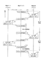
- FIG. 3 is a diagram showing an example of a processing procedure of the communication device according to the embodiment of the present invention.
- FIG. 4 is a flowchart showing detailed processing steps of the active side interlock execution step according to the embodiment of the present invention.
- FIG. 5 is a flowchart showing detailed processing steps of the Passive side interlock execution step according to the embodiment of the present invention.
- FIG. 6 is a flowchart showing detailed processing steps of the Passive signal reception step of the communication device according to the embodiment of the present invention.
- FIG. 1 is an external view showing an outline of a semiconductor manufacturing system.
- the semiconductor manufacturing system 1 mainly includes a communication device 10, a semiconductor manufacturing apparatus 50, a mounting port 20, a travel route 2, a transport cart 30, and an access point 40.
- 1 is an apparatus for processing a wafer, and includes a FOUP loading / unloading port 51 for loading and unloading a FOUP (Front Opening Unified Pod) 100 in which the wafer is stored.
- FOUP Front Opening Unified Pod
- the mounting port 20 is a port on which the FOUP 100 that is the object to be transported is placed, and is placed near the FOUP loading / unloading port 51 of the semiconductor manufacturing apparatus 50 and delivers the semiconductor manufacturing apparatus 50 and the FOUP 100.
- the mounting port 20 transfers the FOUP 100 to and from the transport cart 30.
- the placement port 20 includes a parallel interface 21 and transmits / receives a signal to / from the communication device 10 via the parallel cable 60.
- the transport cart 30 is a cart that transfers the FOUP 100 to and from the placement port 20 and transports it along the travel route 2, and includes a grip portion 31 that grips the FOUP 100 inside.
- the grip portion 31 is provided so as to be movable up and down, and is lowered to the vicinity of the placement port 20 when the FOUP 100 is transferred to and from the placement port 20.
- the communication device 10 is a device that mediates transmission / reception of signals between the placement port 20 and the transport carriage 30.
- the communication device 10 includes a parallel interface 11 and transmits / receives a parallel signal to / from the parallel interface 21 of the placement port 20 via the parallel cable 60.
- the communication device 10 further includes a LAN port 12 and transmits / receives packets to / from the transport carriage 30 via the LAN cable 70 and the access point 40.
- the access point 40 is a device that mediates transmission / reception of packets between the transport cart 30 and the communication device 10.
- the access point 40 transmits the packet received from the communication device 10 via the LAN cable 70 to the transport cart 30 by wireless communication (for example, IEEE 802.11), and the packet received from the transport cart 30 by wireless communication is transmitted to the LAN.
- the data is transmitted to the communication device 10 via the cable 70.
- FIG. 2 is a block diagram showing a characteristic functional configuration of a semiconductor manufacturing apparatus including a communication device.
- the transport cart 30 functionally includes a cart control unit 32 and a cart communication unit 33.
- the carriage control unit 32 receives a signal indicating information on the placement port 20 from the carriage communication unit 33 and controls the operation of the transport carriage 30. Further, the carriage control unit 32 transmits a packet indicating the state of the transport carriage 30 to the carriage communication unit 33.
- the cart communication unit 33 transmits the packet indicating the state of the transport cart 30 transmitted from the cart control unit 32 to the access point 40 by wireless communication. In addition, the cart communication unit 33 receives the packet transmitted from the access point 40 and transmits the packet to the cart control unit 32.
- the placement port 20 functionally includes an LP control unit 22 and a parallel interface 21.
- the LP control unit 22 receives a parallel signal indicating the state of the transport carriage 30 from the parallel interface 21 and controls the placement port 20.
- the LP control unit 22 transmits a parallel signal indicating the state of the placement port 20 to the parallel interface 21.
- the parallel interface 21 is an input / output unit that inputs and outputs parallel signals, and includes a receptacle for connecting a connector (Dsub-25pin) included in the parallel cable 60.
- the communication device 10 functionally includes a parallel interface 11, a LAN port 12, a control unit 13, and a network communication unit 14.
- the parallel interface 11 is an interface that communicates with the placement port 20, and includes an 8-bit one-way and bi-directional 16-bit IO port to which a parallel cable 60 is connected.
- the control unit 13 In the interlock sequence for transferring the FOUP 100 between the placement port 20 and the transport carriage 30, the control unit 13 repeatedly performs communication processing between the placement port 20 and the transport carriage 30 at a predetermined communication cycle. It is a processing unit.
- the control unit 13 performs at least the following six processes in the communication process.
- the standby period is set to the first time interval, and when an error occurs in the interlock sequence, the standby period is set to the second time interval shorter than the first time interval. The process to set for the time interval.
- the control unit 13 includes a CPU, a storage unit, and the like for performing the communication process.
- the network communication unit 14 is a communication unit that communicates with the transport cart 30 via a network.
- the LAN port 12 is an input / output unit that inputs and outputs packets, and is connected to a LAN cable 70.
- FIG. 3 is a diagram illustrating an example of a processing procedure when the communication device 10 performs communication processing based on the E84 interlock sequence when transferring the FOUP 100 between the mounting port 20 and the transport carriage 30. is there.
- the Passive side in the E84 interlock sequence is the placement port 20, and the Active side is the transport carriage 30.
- the E84 interlock sequence is composed of a plurality of steps, and each time the steps on the Active side and the Passive side are completed without error, the value of each bit of the parallel signal on the Active side or 8 bits on the Passive side is updated.
- the next process is executed, and when it is determined that an error has occurred, the interlock sequence is interrupted.
- packets corresponding to the parallel signals of the active side 8 bits and the passive side 8 bits are transmitted and received between the active transport cart 30 and the communication device 10.
- the communication device 10 repeats the communication process of the process steps S1 to S6 of FIG. Further, for example, when an error has occurred on the Passive side, the communication process of the process steps S6 to S11 of FIG. 3 is executed. Hereinafter, each processing step will be described.
- the communication device 10 transmits a packet indicating the state of the placement port 20 on the Passive side to the transport carriage 30 on the Active side by wireless communication.
- the transport carriage 30 on the Active side receives the packet from the communication device 10 and detects the state on the Passive side. And if the conveyance trolley 30 confirms that the error on the E84 interlock sequence has not occurred, the next step of the E84 interlock sequence is executed, and the packet indicating the state of the conveyance trolley 30 after the execution is transmitted to the communication device. 10 is transmitted by wireless communication.
- the communication device 10 receives the packet transmitted from the transport carriage 30, converts it into a parallel signal, and transmits it to the mounting port 20 on the Passive side via the parallel interface 11. To do.
- the placement port 20 receives a parallel signal indicating the state of the Active side from the communication device 10, and detects the state of the Active side. When it is confirmed that no error has occurred in the E84 interlock sequence, the placement port 20 executes the next step of the E84 interlock sequence, and a parallel signal indicating the state of the placement port 20 after execution. Is transmitted from the parallel interface 21.
- the communication device 10 receives the parallel signal from the placement port 20 and converts it into a packet. Furthermore, the state of the mounting port 20 is determined based on the parallel signal received from the mounting port 20.
- the communication device 10 determines that an error in the E84 interlock sequence has not occurred in the placement port 20, the communication device 10 enters a standby state.
- the communication device 10 performs the Passive side signal transmission process (S6). In the Passive side signal transmission process, the communication device 10 transmits a packet indicating the state of the placement port 20 to the transport carriage 30 by wireless communication.
- the first time interval is preferably set to a value that suppresses the communication data amount and does not take too much time to execute the interlock sequence.
- processing steps S6 to S12 in FIG. 3 will be described.
- processing steps S6 to S8 processing is performed in the same manner as the processing steps S1 to S3 described above.
- the Passive side interlock execution step (S9) the placement port 20 receives a parallel signal indicating the state on the Active side from the communication device 10, and detects the state on the Active side.
- the mounting port 20 executes the next step of the E84 interlock sequence.
- the mounting port 20 transmits a parallel signal indicating a state where the error has occurred from the parallel interface 21.
- the communication device 10 receives the parallel signal from the mounting port 20 and detects the state of the mounting port 20.
- the communication device 10 confirms that an error in the E84 interlock sequence has occurred in the placement port 20
- the communication device 10 converts the parallel signal received from the placement port 20 into a packet and waits.
- the communication device 10 performs a Passive side signal transmission process (S11).
- the communication device 10 transmits a packet indicating the state of the placement port 20 to the transport carriage 30 by wireless communication, similarly to the processing step S6 described above.
- the communication device 10 when an error occurs in the E84 interlock sequence, the communication device 10, the loading port 20, and the transport carriage 30 perform the processing steps from S6 to S11 in the second cycle shorter than the first cycle. Execute. Then, in the active side interlock execution step (S12), the transport carriage 30 receives the packet from the communication device 10 and detects the state on the passive side. Then, when it is confirmed on the Passive side that an error on the E84 interlock sequence has occurred, the transport carriage 30 interrupts the E84 interlock sequence.
- the second time interval is an interlock sequence while reliably receiving a signal on the Passive side (while ensuring a time for chattering processing when reading a signal of an IO port). It is set to a value that ensures the safety.
- the standby period is provided in the Passive signal reception process, but it may be provided in other processes such as the Active side interlock execution process or Passive side interlock execution process, or in a plurality of processes. May be.
- time interval may not be fixed.
- an interface for input may be provided in the communication device 10, and each time interval and period stored in the storage unit in the control unit 13 may be changed from an external input device via this interface. According to this configuration, each time interval and cycle can be adjusted to appropriate values as needed.
- the first time interval described above may be changed according to the processing steps of each interlock sequence. According to this configuration, since an appropriate time interval and cycle can be adopted according to the time required for each processing step of the interlock sequence, it is possible to avoid performing communication with a cycle shorter than necessary, and communication data The amount can be suppressed. For example, in the interlock sequence, when there is a process that is unlikely to cause an error and requires a time sufficiently longer than the first time interval, the first time interval is set according to the time required for the process. It may be longer.
- the above-described second time interval may be changed according to the type of error. For example, in the case of a dangerous error such as when it is detected that an operator approaches the mounting port 20, the second time interval is shortened as much as possible, and in the case of a minor error such as a communication error, It is good also as a structure which lengthens a 2nd time interval. According to this configuration, it is possible to adopt an appropriate second time interval according to the risk of error, urgency, etc., so it is possible to avoid performing communication at intervals shorter than necessary, and to reduce the amount of communication data Can be suppressed.
- FIG. 4 is a flowchart showing detailed processing steps of the active side interlock execution step.
- the transport carriage 30 on the Active side receives a packet indicating the state of the loading port 20 on the Passive side (S21).
- the transport carriage 30 updates a signal indicating the state of the mounting port 20 stored therein (S22).
- it is determined whether or not an error has occurred in the loading port 20 S23. If it is determined in the processing step S23 that an error has occurred, the transport carriage 30 interrupts the interlock sequence (S26). If it is determined in the processing step S23 that no error has occurred, the Active side interlock sequence is continued (S24).
- the interlock sequence it is determined whether or not an error has occurred in the transport carriage 30 on the active side (S25).
- the interlock sequence is interrupted (S26).
- the transfer cart 30 stored in the transport cart 30 on the active side is stored.
- the signal indicating the state is updated (S27).
- the packet which shows the state of the updated conveyance trolley 30 is transmitted to the communication device 10 from the conveyance trolley 30 (S28), and an Active side interlock execution process is complete
- FIG. 5 is a flowchart showing detailed processing steps of the Passive side interlock execution step.
- the placement port 20 on the Passive side receives a parallel signal indicating the state of the transport carriage 30 on the Active side via the parallel interface 21 (S31).
- a parallel signal indicating the state of the transport carriage 30 S32. If it is determined in the processing step S32 that an error has occurred, the placement port 20 interrupts the interlock sequence (S35). If it is determined in the processing step S32 that no error has occurred, the Passive side interlock sequence is continued (S33). Then, in the interlock sequence, it is determined whether or not an error has occurred in the mounting port 20 on the Passive side (S34).
- the interlock sequence is interrupted (S35).
- the parallel signal indicating the state of the placement port 20 is updated, and the parallel interface 21 To the communication device 10 (S36). This completes the Passive side interlock execution process.
- FIG. 6 is a flowchart showing detailed processing steps of the Passive signal receiving step.
- the communication device 10 receives a parallel signal indicating the state of the placement port 20 on the Passive side (S41). Next, the received parallel signal is converted into a packet (S42). Then, based on the received parallel signal, it is determined whether or not an error has occurred in the placement port 20 (S43). If it is determined in the processing step S43 that no error has occurred, the communication device 10 waits until the first time interval elapses from the time when the parallel signal is received from the placement port 20 (S44). If it is determined in the processing step S43 that an error has occurred, the communication device 10 has passed a second time interval shorter than the first time interval from the time when the parallel signal was received from the placement port 20. (S45), and the Passive signal reception process ends.
- the communication interval between the transport carriage and the placement port is set. Since it can be shortened, error information can be transmitted without delay. Further, when no error has occurred, the communication cycle between the transport carriage and the placement port can be made longer than when an error has occurred, so that the amount of communication data can be suppressed.
- the communication device of the present invention has been described based on the embodiment, the present invention is not limited to this embodiment. Unless it deviates from the meaning of this invention, the form which carried out the various deformation
- the interlock sequence is interrupted when an error has occurred, but the interlock sequence may be tried again depending on the type of error. For example, when only a communication error occurs, the communication may be retried without interrupting the interlock sequence.
- the present invention can be used for a communication device that performs communication between a placement port on which a transported object is placed and a transport carriage that transports and transfers the transported object.
Landscapes
- Engineering & Computer Science (AREA)
- General Engineering & Computer Science (AREA)
- Manufacturing & Machinery (AREA)
- Quality & Reliability (AREA)
- Physics & Mathematics (AREA)
- General Physics & Mathematics (AREA)
- Automation & Control Theory (AREA)
- Container, Conveyance, Adherence, Positioning, Of Wafer (AREA)
- Control Of Position, Course, Altitude, Or Attitude Of Moving Bodies (AREA)
Abstract
通信デバイス(10)は、載置ポート(20)との間で通信するパラレルインタフェース(11)と、搬送台車(30)とネットワークを介して通信するネットワーク通信部(14)と、パラレルインタフェース(11)及びネットワーク通信部(14)を制御する制御部(13)と、を備え、制御部(13)は、載置ポート(20)と搬送台車(30)との間で被搬送物を移載するためのインターロックシーケンスにおいて、載置ポート(20)の信号を入力してから、パケットを搬送台車(30)に送信するまでの間に所定の待機期間をおき、この所定の待機期間は、エラーの有無に応じて変更される。
Description
本発明は、通信デバイスに関し、特に、被搬送物を載置する載置ポートと、被搬送物を搬送及び移載する搬送台車との間で通信を行う通信デバイス及びその制御方法に関する。
半導体製造装置に設けられた載置ポートと、天井走行台車などの搬送台車との間の通信には、SEMI(Semiconductor Equipment and Materials International)のE84通信シーケンスが適用される。ウェハ等を収納したポッドを被搬送物として、天井走行台車により搬送し、載置ポートに移載する際、及び、載置ポートからポッドを搬出する際には、E84通信シーケンスで、天井走行台車と載置ポートとの間で制御信号が授受される。例えば、天井走行台車よりポッドを載置ポートに移載する際、特定の信号(L_REQ)がオフとならないと、次の工程には移行しないような複数の工程からなるインターロックシーケンスが採用されている(例えば、特許文献1参照)。これにより、天井走行台車から載置ポートへのポッドの移載を安全かつ確実に行おうとしている。
E84通信シーケンスにおける載置ポートと天井走行台車との通信は、8bit(片方向8bit、双方向で16bit)のパラレルインタフェースが使用されている。天井走行台車の走行経路には、光通信装置が配置され、この光通信装置と天井走行台車は光で信号をやり取りする。また、光通信機器と載置ポートとの間は、パラレルインタフェースケーブルで接続される。このようなパラレルインタフェースと光通信機器を用いる場合には、載置ポート単位で通信機器を配置する必要があるためコストが上昇する問題がある。
そこで、パラレルインタフェースに変えて、LAN(Local Area Network)などのネットワーク通信によって、入出力ポート(以下IOポートという)の情報を伝達する構成が考えられる。本構成においては、IOポートの情報であるパラレル信号がパケットに変換され、ネットワークを経由して伝達される。
パラレルインタフェースによって情報を伝達する場合は、パラレルインタフェースのIOポートの情報が常時接続先に伝達される。一方、ネットワーク通信を用いる構成においては、所定のタイミングでパケットが送信される。ネットワーク通信を用いる構成において、パラレルインタフェースの入出力ポートの情報を、ネットワーク通信によって送信先に伝達する一つのタイミングとして、IOポートの情報が変化したタイミングを採用することが考えられる(例えば、特許文献2参照)。この場合には、情報が変化するまで情報が送信されないので、実際に情報が変化していないのか、それとも、故障などにより情報を送信できない状態になっているのか、を判別できない問題がある。
また、IOポートの情報を送信先の相手に伝達する他のタイミングとして、予め定められた一定時間間隔のタイミングを採用することが考えられる(例えば、特許文献3参照)。この場合には、一定時間間隔で通信を続けるため、相手の状態を定期的に確認できるものの、遅滞なくエラーを検知するためには、時間間隔を短くしなければならず、通信データ量が増加するという問題がある。
本発明は、上記問題を解決するためのものであり、被搬送物を載置する載置ポートと、被搬送物の搬送及び移載を行う搬送台車との間の通信を行う通信デバイスにおいて、通信データ量の増加を抑制しつつ、遅滞なくエラー情報を伝達することを目的とする。
上記課題を解決するために、本発明の一態様に係る通信デバイスは、被搬送物が載置される載置ポートとの間で通信するパラレルインタフェースと、前記載置ポートとの間で前記被搬送物を移載する搬送台車とネットワークを介して通信するネットワーク通信部と、前記パラレルインタフェース及び前記ネットワーク通信部を制御する制御部と、を備え、前記制御部は、前記載置ポートと前記搬送台車との間で前記被搬送物を移載するためのインターロックシーケンスにおいて、前記載置ポート及び前記搬送台車との通信処理を繰り返し、前記通信処理は、前記ネットワーク通信部で受信された第1のパケットを第1のパラレル信号に変換する処理と、前記第1のパラレル信号を前記パラレルインタフェースから出力する処理と、前記パラレルインタフェースから入力された第2のパラレル信号を第2のパケットに変換する処理と、所定の待機期間をおいて、前記第2のパケットを前記ネットワーク通信部から前記搬送台車に送信する処理と、前記第1のパケット又は前記第2のパラレル信号に基づき、前記インターロックシーケンスにおけるエラーが生じているかを判定する処理と、前記インターロックシーケンスにおけるエラーが生じていない場合には、前記所定の待機期間を第1の時間間隔に設定し、前記インターロックシーケンスにおけるエラーが生じている場合には、前記所定の待機期間を前記第1の時間間隔より短い第2の時間間隔に設定する処理と、を含む。
これによれば、インターロックシーケンスにおいて、エラーが発生している場合には、搬送台車と載置ポートとの間の通信の周期を短くできるため、エラー情報を遅滞なく伝達することができる。また、エラーが発生していない場合には、エラーが発生している場合より、搬送台車と載置ポートとの間の通信の周期を長くできるため、通信データ量を抑制することができる。
また、本発明の一態様に係る通信デバイスとして、前記パラレルインタフェースは、SEMI E84規格に基づく構成を有する構成としてもよい。
これによれば、SEMI E84規格のインターロックシーケンスを採用することができる。
また、本発明の一態様に係る通信デバイスとして、前記第1の時間間隔及び第2の時間間隔の少なくとも一方を、外部から変更するためのインタフェースをさらに備える構成としてもよい。
これによれば、第1の時間間隔及び第2の時間間隔を、外部から、随時適切な値に調整することができる。
また、本発明の一態様に係る通信デバイスとして、前記制御部は、前記インターロックシーケンスにおけるエラーの種類に応じて、前記第2の時間間隔を変更する構成としてもよい。
これによれば、エラーの危険性、緊急性などに応じて、第2の時間間隔を必要十分な値に設定することができるため、通信データ量をより抑制することができる。
上記課題を解決するために、本発明の一態様に係る通信デバイスの制御方法は、被搬送物が載置される載置ポートとの間で通信するパラレルインタフェースと、前記載置ポートとの間で前記被搬送物を移載する搬送台車とネットワークを介して通信するネットワーク通信部と、前記パラレルインタフェース及び前記ネットワーク通信部を制御する制御部と、を備える通信デバイスの制御方法であって、前記載置ポートと前記搬送台車との間で前記被搬送物を移載するためのインターロックシーケンスにおいて繰り返される、前記載置ポート及び前記搬送台車との通信処理を含み、前記通信処理は、前記ネットワーク通信部で受信された第1のパケットを第1のパラレル信号に変換する処理と、前記第1のパラレル信号を前記パラレルインタフェースから出力する処理と、前記パラレルインタフェースから入力された第2のパラレル信号を第2のパケットに変換する処理と、所定の待機期間をおいて、前記第2のパケットを前記ネットワーク通信部から前記搬送台車に送信する処理と、前記第1のパケット又は前記第2のパラレル信号に基づき、前記インターロックシーケンスにおけるエラーが生じているかを判定する処理と、前記インターロックシーケンスにおけるエラーが生じていない場合においては、前記所定の待機期間を第1の時間間隔に設定し、前記インターロックシーケンスにおけるエラーが生じている場合においては、前記所定の待機期間を前記第1の時間間隔より短い第2の時間間隔に設定する処理と、を含む。
これによれば、インターロックシーケンスにおいて、エラーが発生している場合には、搬送台車と載置ポートとの間の通信の間隔を短くできるため、エラー情報を遅滞なく伝達することができる。また、エラーが発生していない場合には、エラーが発生している場合より、搬送台車と載置ポートとの間の通信の間隔を長くできるため、通信データ量を抑制することができる。
なお、本発明は、装置及び制御方法として実現できるだけでなく、制御方法におけるステップをコンピュータに実行させるプログラムとして実現することもできる。また、そのプログラムを記録したコンピュータ読み取り可能な記録媒体として実現すること、及び、そのプログラムを示す情報、データ又は信号として実現することもできる。そして、それらプログラム、情報、データ及び信号は、インターネット等の通信ネットワークを介して配信してもよい。
本発明により、被搬送物を載置する載置ポートと、被搬送物の搬送及び受け渡しを行う搬送台車との間の通信を行う通信デバイスにおいて、通信データ量の増加を抑制しつつ、遅滞なくエラー情報を伝達することができる。
以下、本発明の実施の形態について、図面を用いて詳細に説明する。なお、以下で説明する実施の形態は、いずれも本発明の好ましい一具体例を示すものである。以下の実施の形態で示される数値、形状、材料、構成要素、構成要素の配置位置及び接続形態、ステップ、ステップの順序などは、一例であり、本発明を限定する主旨ではない。また、以下の実施の形態における構成要素のうち、本発明の最上位概念を示す独立請求項に記載されていない構成要素については、より好ましい形態を構成する任意の構成要素として説明される。
なお、同一の構成要素には同一の符号を付し、説明を省略する場合がある。
まず、本発明に係る通信デバイスを含む半導体製造システムの実施の形態の概要を説明する。図1は、半導体製造システムの概要を示す外観図である。図1に示されるように、半導体製造システム1は、主に、通信デバイス10、半導体製造装置50、載置ポート20、走行ルート2、搬送台車30及びアクセスポイント40から構成される。
図1に示される半導体製造装置50は、ウェハを加工する装置であり、ウェハが格納されたFOUP(Front Opening Unified Pod)100を搬入及び搬出するためのFOUP搬入搬出口51を備える。
載置ポート20は、被搬送物であるFOUP100が載置されるポートであり、半導体製造装置50のFOUP搬入搬出口51付近に配置されて、半導体製造装置50とFOUP100を受け渡しする。また、載置ポート20は、搬送台車30との間で、FOUP100を移載する。また、載置ポート20は、パラレルインタフェース21を有し、パラレルケーブル60を介して、通信デバイス10との間で信号を送受信する。
搬送台車30は、載置ポート20との間でFOUP100を移載し、走行ルート2に沿って搬送する台車であり、内部にFOUP100を把持する把持部31を備える。把持部31は、昇降可能に設けられており、FOUP100を載置ポート20との間で移載する際には、載置ポート20付近まで降下される。
通信デバイス10は、載置ポート20と搬送台車30との間の信号の送受信を仲介するデバイスである。通信デバイス10は、パラレルインタフェース11を備え、パラレルケーブル60を介して、載置ポート20のパラレルインタフェース21との間でパラレル信号を送受信する。また、通信デバイス10は、さらに、LANポート12を備え、LANケーブル70及びアクセスポイント40を介して、搬送台車30との間でパケットを送受信する。
アクセスポイント40は、搬送台車30と通信デバイス10との間のパケットの送受信を仲介するデバイスである。アクセスポイント40は、通信デバイス10からLANケーブル70を介して受信したパケットを、無線通信(例えばIEEE 802.11)によって搬送台車30に送信し、搬送台車30から無線通信によって受信したパケットを、LANケーブル70を介して通信デバイス10に送信する。
次に、本実施の形態の半導体製造装置の機能構成を説明する。図2は、通信デバイスを含む半導体製造装置の特徴的な機能構成を示すブロック図である。
まず、図2に示される搬送台車30の機能構成について説明する。図2に示されるように、搬送台車30は、機能的には、台車制御部32及び台車通信部33を含む。台車制御部32は、台車通信部33から載置ポート20の情報を示す信号を受信して、搬送台車30の動作を制御する。また、台車制御部32は、搬送台車30の状態を示すパケットを台車通信部33に送信する。台車通信部33は、台車制御部32から送信された搬送台車30の状態を示すパケットを、無線通信によって、アクセスポイント40に送信する。また、台車通信部33は、アクセスポイント40から送信されたパケットを受信して、台車制御部32に送信する。
次に、図2に示される載置ポート20の機能構成について説明する。図2に示されるように、載置ポート20は、機能的には、LP制御部22とパラレルインタフェース21とを含む。LP制御部22は、パラレルインタフェース21から搬送台車30の状態を示すパラレル信号を受信して、載置ポート20を制御する。また、LP制御部22は、載置ポート20の状態を示すパラレル信号をパラレルインタフェース21に送信する。パラレルインタフェース21は、パラレル信号を入出力する入出力部であって、パラレルケーブル60が備えるコネクタ(Dsub-25pin)を接続するためのレセプタクルを含む。
次に、図2に示される通信デバイス10の機能構成について説明する。図2に示されるように、通信デバイス10は、機能的には、パラレルインタフェース11、LANポート12、制御部13及びネットワーク通信部14を含む。パラレルインタフェース11は、載置ポート20との間で通信するインタフェースであって、片方8bit、双方向で16bitのIOポートを含み、パラレルケーブル60が接続される。制御部13は、載置ポート20と搬送台車30との間でFOUP100を移載するためのインターロックシーケンスにおいて、載置ポート20及び搬送台車30との通信処理を、所定の通信周期で繰り返し行う処理部である。制御部13は通信処理において少なくとも以下の六つの処理を行う。
(1)ネットワーク通信部14から送信されたパケットをパラレル信号に変換する処理。
(2)パケットから変換されたパラレル信号を各IOポートに書き込み(WRITE)、パラレルインタフェース11から出力する処理。
(3)パラレルインタフェース11から入力されたパラレル信号を各IOポートから読み出し(READ)、パケットに変換する処理。
(4)パラレル信号から変換されたパケットをネットワーク通信部14に送信する処理。
(5)受信したパケット及びパラレル信号に基づき、載置ポート20と搬送台車30との間のFOUP100移載のインターロックシーケンスにおけるエラーが生じているかを判定する処理。
(6)エラーが生じていない場合においては、待機期間を第1の時間間隔に設定し、インターロックシーケンスにおけるエラーが生じている場合においては、待機期間を第1の時間間隔より短い第2の時間間隔に設定する処理。
制御部13は、上記通信処理を行うためのCPUや記憶部等を内部に備える。
ネットワーク通信部14は、搬送台車30とネットワークを介して通信する通信部である。LANポート12は、パケットを入出力する入出力部であって、LANケーブル70が接続される。
次に、本実施の形態の半導体製造システム1の通信処理の動作について説明する。図3は、載置ポート20と搬送台車30との間でFOUP100の移載を行う際に、E84インターロックシーケンスに基づいて通信デバイス10が通信処理を行う場合の処理手順の一例を示す図である。本通信処理において、E84インターロックシーケンスにおけるPassive側が載置ポート20であり、Active側が搬送台車30である。E84インターロックシーケンスは、複数の工程からなり、Active側及びPassive側の各工程がエラーなく完了する毎に、Active側8bit又はPassive側8bitのパラレル信号の各bitの値が更新される。そして、前の工程でエラーが発生しなかったことをパラレル信号によって判定された場合には次の工程が実行され、エラーが発生したと判定された場合にはインターロックシーケンスが中断される。なお、本実施の形態においては、Active側の搬送台車30と通信デバイス10との間で、Active側8bit、Passive側8bitのパラレル信号に対応するパケットが送受信される。
本実施の形態において、Active側及びPassive側にE84インターロックシーケンス上のエラーが発生していない場合には、通信デバイス10は、図3の処理工程S1~S6の通信処理を繰り返す。また、例えば、Passive側にエラーが発生している場合には、図3の処理工程S6~S11の通信処理を実行する。以下、各処理工程について説明する。
まず、図3において処理工程S1~S6で示されるE84インターロックシーケンス上のエラーが発生しない場合の処理工程について説明する。Passive信号送信工程(S1)においては、通信デバイス10が、Passive側である載置ポート20の状態を示すパケットを、Active側である搬送台車30に無線通信により送信する。続くActive側インターロック実行工程(S2)において、Active側である搬送台車30が、通信デバイス10からのパケットを受信して、Passive側の状態を検知する。そして、搬送台車30は、E84インターロックシーケンス上のエラーが発生していないことを確認すると、E84インターロックシーケンスの次の工程を実行し、実行後の搬送台車30の状態を示すパケットを通信デバイス10に無線通信により送信する。次のActive信号転送工程(S3)において、搬送台車30から送信されたパケットを通信デバイス10が受信して、パラレル信号に変換し、パラレルインタフェース11を介して、Passive側の載置ポート20に送信する。続くPassive側インターロック実行工程(S4)において、載置ポート20は、通信デバイス10からActive側の状態を示すパラレル信号を受信して、Active側の状態を検知する。そして、E84インターロックシーケンス上のエラーが発生していないことを確認すると、載置ポート20は、E84インターロックシーケンスの次の工程を実行し、実行後の載置ポート20の状態を示すパラレル信号をパラレルインタフェース21から送信する。次に、Passive信号受信工程(S5)において、通信デバイス10は載置ポート20からのパラレル信号を受信し、パケットに変換する。さらに、載置ポート20から受信したパラレル信号に基づいて載置ポート20の状態を判定する。ここで、通信デバイス10は、載置ポート20において、E84インターロックシーケンス上のエラーが発生していないと判定すると待機状態となる。そして、パラレル信号受信から第1の時間間隔が経過した後、通信デバイス10は、Passive側信号送信工程(S6)を実行する。Passive側信号送信工程において、通信デバイス10は、搬送台車30に、載置ポート20の状態を示すパケットを搬送台車30に無線通信により送信する。上述のとおり、エラーが発生しない場合、通信デバイス10、載置ポート20及び搬送台車30は、S1からS6までの処理工程を図3に示されるように、インターロックシーケンスの全工程が終了するまで繰り返し実行する。なお、第1の時間間隔としては、通信データ量が抑制され、かつ、インターロックシーケンスの実行に時間がかかり過ぎないような値に設定されることが好ましい。
次に、図3において処理工程S6~S12で示されるE84インターロックシーケンス上のエラーが発生する場合の処理工程について説明する。まず、処理工程S6~S8においては上述した処理工程S1~S3と同様に処理が行われる。次に、Passive側インターロック実行工程(S9)において、載置ポート20は、通信デバイス10からActive側の状態を示すパラレル信号を受信して、Active側の状態を検知する。そして、E84インターロックシーケンス上のエラーが発生していないことを確認すると、載置ポート20は、E84インターロックシーケンスの次の工程を実行する。ここで、本インターロックシーケンスの工程においてエラーが発生すると仮定すると、載置ポート20は、エラーが発生している状態を示すパラレル信号をパラレルインタフェース21から送信する。次に、Passive信号受信工程(S10)において、通信デバイス10は載置ポート20からのパラレル信号を受信し、載置ポート20の状態を検知する。ここで、通信デバイス10は、載置ポート20において、E84インターロックシーケンス上のエラーが発生していることを確認すると、載置ポート20から受信したパラレル信号をパケットに変換して待機する。そして、パラレル信号受信から、第1の時間間隔より短い第2の時間間隔が経過した後、通信デバイス10は、Passive側信号送信工程(S11)を実行する。Passive側信号送信工程において、上述した処理工程S6と同様に、通信デバイス10は、載置ポート20の状態を示すパケットを搬送台車30に無線通信により送信する。上述のとおり、通信デバイス10、載置ポート20及び搬送台車30は、E84インターロックシーケンス上のエラーが発生する場合、S6からS11までの処理工程を、第1の周期より短い第2の周期で実行する。そして、Active側インターロック実行工程(S12)において、搬送台車30が、通信デバイス10からのパケットを受信して、Passive側の状態を検知する。そして、Passive側でE84インターロックシーケンス上のエラーが発生していることを確認すると、搬送台車30は、E84インターロックシーケンスを中断する。なお、本実施の形態における、第2の時間間隔は、Passive側の信号の受信を確実に行いつつ(IOポートの信号を読み取る際のチャタリング処理のための時間を確保しつつ)、インターロックシーケンスの安全を確保するような値に設定される。
また、本実施の形態においては、待機期間をPassive信号受信工程に設けたが、Active側インターロック実行工程又はPassive側インターロック実行工程など他の工程に設けてもよいし、複数の工程に設けてもよい。
なお、上述の時間間隔は、固定されていなくてもよい。例えば、通信デバイス10に入力用のインタフェースを設けて、このインタフェースを介して外部の入力装置から、制御部13内の記憶部に格納されている各時間間隔及び周期を変更できる構成としてもよい。本構成によれば、各時間間隔及び周期を、随時適切な値に調整することができる。
また、上述の第1の時間間隔を、各インターロックシーケンスの処理工程に応じて変更する構成としてもよい。本構成によれば、インターロックシーケンスの各処理工程に要する時間などに応じて適切な時間間隔及び周期を採用することができるため、必要以上に短い周期で通信を行うことを回避でき、通信データ量を抑制することができる。例えば、インターロックシーケンスの中で、エラーが発生しにくく、かつ、第1の時間間隔より十分長い時間を要する処理がある場合には、当該処理に要する時間に応じて、第1の時間間隔を長くしてもよい。
また、上述の第2の時間間隔を、エラーの種類に応じて変更する構成としてもよい。例えば、載置ポート20付近に作業員が接近したことを検知した場合などの危険なエラーの場合には、第2の時間間隔を極力短くし、通信エラーなどの軽微なエラーの場合には、第2の時間間隔を長くする構成としてもよい。本構成によれば、エラーの危険性、緊急性などに応じて適切な第2の時間間隔を採用することができるので、必要以上に短い間隔で通信を行うことを回避でき、通信データ量を抑制することができる。
次に、図3に示されるActive側インターロック実行工程内の詳細な処理工程について図4を用いて説明する。図4は、Active側インターロック実行工程の詳細な処理工程を示すフローチャートである。
まず、Active側インターロック実行工程が開始されると、Active側である搬送台車30は、Passive側である載置ポート20の状態を示すパケットを受信する(S21)。次に、搬送台車30は、内部に記憶されている載置ポート20の状態を示す信号を更新する(S22)。続いて、更新された載置ポート20の状態を示す信号に基づいて、載置ポート20においてエラーが発生したか否かを判定する(S23)。処理工程S23でエラーが発生したと判定された場合には、搬送台車30は、インターロックシーケンスを中断する(S26)。また、処理工程S23でエラーが発生しなかったと判定された場合には、Active側のインターロックシーケンスを続行する(S24)。そして、インターロックシーケンスにおいて、Active側である搬送台車30でエラーが発生したか否かを判定する(S25)。処理工程S25でエラーが発生したと判定された場合には、インターロックシーケンスを中断する(S26)。また、処理工程S25でエラーが発生しなかったと判定された場合、及び、処理工程S26においてインターロックシーケンスが中断された場合には、Active側である搬送台車30に記憶されている搬送台車30の状態を示す信号が更新される(S27)。そして、更新された搬送台車30の状態を示すパケットが、搬送台車30から、通信デバイス10に送信され(S28)、Active側インターロック実行工程が終了する。
次に、図3に示されるPassive側インターロック実行工程内の詳細な処理工程について図5を用いて説明する。図5は、Passive側インターロック実行工程の詳細な処理工程を示すフローチャートである。
まず、Passive側インターロック実行工程が開始されると、Passive側である載置ポート20は、パラレルインタフェース21を介してActive側である搬送台車30の状態を示すパラレル信号を受信する(S31)。次に、受信された搬送台車30の状態を示すパラレル信号に基づいて、搬送台車30においてエラーが発生したか否かを判定する(S32)。処理工程S32でエラーが発生したと判定された場合には、載置ポート20は、インターロックシーケンスを中断する(S35)。また、処理工程S32でエラーが発生しなかったと判定された場合には、Passive側のインターロックシーケンスを続行する(S33)。そして、インターロックシーケンスにおいて、Passive側である載置ポート20でエラーが発生したか否かを判定する(S34)。処理工程S34でエラーが発生したと判定された場合には、インターロックシーケンスを中断する(S35)。処理工程S34でエラーが発生しなかったと判定された場合、及び、処理工程S35においてインターロックシーケンスが中断された場合には、載置ポート20の状態を示すパラレル信号が更新されて、パラレルインタフェース21から通信デバイス10に送信される(S36)。以上で、Passive側インターロック実行工程が終了する。
次に、図3に示されるPassive信号受信工程の詳細な処理工程について図6を用いて説明する。図6は、Passive信号受信工程の詳細な処理工程を示すフローチャートである。
まず、Passive信号受信工程が開始されると、通信デバイス10において、Passive側である載置ポート20の状態を示すパラレル信号を受信する(S41)。次に、受信したパラレル信号をパケットに変換する(S42)。そして、受信したパラレル信号に基づいて、載置ポート20においてエラーが発生したが否かを判定する(S43)。処理工程S43で、エラーが発生しなかったと判定された場合には、通信デバイス10は、載置ポート20からパラレル信号を受信した時点から第1の時間間隔が経過するまで待機する(S44)。また、処理工程S43で、エラーが発生したと判定された場合には、通信デバイス10は、載置ポート20からパラレル信号を受信した時点から第1の時間間隔より短い第2の時間間隔が経過するまで待機し(S45)、Passive信号受信工程が終了する。
以上のように、本実施の形態に係る通信デバイスによれば、E84インターロックシーケンスを実行する際、エラーが発生している場合には、搬送台車と載置ポートとの間の通信の間隔を短くできるため、エラー情報を遅滞なく伝達することができる。また、エラーが発生していない場合には、エラーが発生している場合より、搬送台車と載置ポートとの間の通信の周期を長くできるため、通信データ量を抑制することができる。
以上、本発明の通信デバイスについて、実施の形態に基づいて説明したが、本発明は、この実施の形態に限定されるものではない。本発明の趣旨を逸脱しない限り、当業者が思いつく各種変形を本実施の形態に施したものや、異なる実施の形態における構成要素を組み合わせて構築される形態も、本発明の範囲内に含まれる。
例えば、図3~5に示される処理例においては、エラーが発生している場合にインターロックシーケンスが中断されるが、エラーの種類によっては、再度インターロックシーケンスを試行する場合もあり得る。例えば、通信上のエラーだけが発生した場合には、インターロックシーケンスを中断せず、通信の再試行を行う場合もあり得る。
また、本実施の形態においては、SEMI E84規格に基づくインターロックシーケンスを実行する例を示したが、本発明は、SEMI E84規格以外のインターロックシーケンスにおいても採用することができる。
本発明は、被搬送物を載置する載置ポートと、被搬送物を搬送及び移載する搬送台車との間で通信を行う通信デバイスに利用することができる。
1 半導体製造システム
2 走行ルート
10 通信デバイス
11、21 パラレルインタフェース
12 LANポート
13 制御部
14 ネットワーク通信部
20 載置ポート
22 LP制御部
30 搬送台車
31 把持部
32 台車制御部
33 台車通信部
40 アクセスポイント
50 半導体製造装置
51 FOUP搬入搬出口
60 パラレルケーブル
70 LANケーブル
100 FOUP
2 走行ルート
10 通信デバイス
11、21 パラレルインタフェース
12 LANポート
13 制御部
14 ネットワーク通信部
20 載置ポート
22 LP制御部
30 搬送台車
31 把持部
32 台車制御部
33 台車通信部
40 アクセスポイント
50 半導体製造装置
51 FOUP搬入搬出口
60 パラレルケーブル
70 LANケーブル
100 FOUP
Claims (5)
- 被搬送物が載置される載置ポートとの間で通信するパラレルインタフェースと、
前記載置ポートとの間で前記被搬送物を移載する搬送台車とネットワークを介して通信するネットワーク通信部と、
前記パラレルインタフェース及び前記ネットワーク通信部を制御する制御部と、を備え、
前記制御部は、前記載置ポートと前記搬送台車との間で前記被搬送物を移載するためのインターロックシーケンスにおいて、前記載置ポート及び前記搬送台車との通信処理を繰り返し、
前記通信処理は、
前記ネットワーク通信部で受信された第1のパケットを第1のパラレル信号に変換する処理と、
前記第1のパラレル信号を前記パラレルインタフェースから出力する処理と、
前記パラレルインタフェースから入力された第2のパラレル信号を第2のパケットに変換する処理と、
所定の待機期間をおいて、前記第2のパケットを前記ネットワーク通信部から前記搬送台車に送信する処理と、
前記第1のパケット又は前記第2のパラレル信号に基づき、前記インターロックシーケンスにおけるエラーが生じているかを判定する処理と、
前記インターロックシーケンスにおけるエラーが生じていない場合には、前記所定の待機期間を第1の時間間隔に設定し、前記インターロックシーケンスにおけるエラーが生じている場合には、前記所定の待機期間を前記第1の時間間隔より短い第2の時間間隔に設定する処理と、
を含む
通信デバイス。 - 前記パラレルインタフェースは、SEMI E84規格に基づく構成を有する
請求項1に記載の通信デバイス。 - 前記第1の時間間隔及び第2の時間間隔の少なくとも一方を、外部から変更するためのインタフェースをさらに備える
請求項1又は2に記載の通信デバイス。 - 前記制御部は、前記インターロックシーケンスにおけるエラーの種類に応じて、前記第2の時間間隔を変更する
請求項1~3のいずれか1項に記載の通信デバイス。 - 被搬送物が載置される載置ポートとの間で通信するパラレルインタフェースと、
前記載置ポートとの間で前記被搬送物を移載する搬送台車とネットワークを介して通信するネットワーク通信部と、
前記パラレルインタフェース及び前記ネットワーク通信部を制御する制御部と、を備える通信デバイスの制御方法であって、
前記載置ポートと前記搬送台車との間で前記被搬送物を移載するためのインターロックシーケンスにおいて繰り返される、前記載置ポート及び前記搬送台車との通信処理を含み、
前記通信処理は、
前記ネットワーク通信部で受信された第1のパケットを第1のパラレル信号に変換する処理と、
前記第1のパラレル信号を前記パラレルインタフェースから出力する処理と、
前記パラレルインタフェースから入力された第2のパラレル信号を第2のパケットに変換する処理と、
所定の待機期間をおいて、前記第2のパケットを前記ネットワーク通信部から前記搬送台車に送信する処理と、
前記第1のパケット又は前記第2のパラレル信号に基づき、前記インターロックシーケンスにおけるエラーが生じているかを判定する処理と、
前記インターロックシーケンスにおけるエラーが生じていない場合においては、前記所定の待機期間を第1の時間間隔に設定し、前記インターロックシーケンスにおけるエラーが生じている場合においては、前記所定の待機期間を前記第1の時間間隔より短い第2の時間間隔に設定する処理と、
を含む
通信デバイスの制御方法。
Applications Claiming Priority (2)
| Application Number | Priority Date | Filing Date | Title |
|---|---|---|---|
| JP2013219643A JP6052132B2 (ja) | 2013-10-22 | 2013-10-22 | 通信デバイス及びその制御方法 |
| JP2013-219643 | 2013-10-22 |
Publications (1)
| Publication Number | Publication Date |
|---|---|
| WO2015059861A1 true WO2015059861A1 (ja) | 2015-04-30 |
Family
ID=52992485
Family Applications (1)
| Application Number | Title | Priority Date | Filing Date |
|---|---|---|---|
| PCT/JP2014/004568 Ceased WO2015059861A1 (ja) | 2013-10-22 | 2014-09-05 | 通信デバイス及びその制御方法 |
Country Status (3)
| Country | Link |
|---|---|
| JP (1) | JP6052132B2 (ja) |
| TW (1) | TWI619662B (ja) |
| WO (1) | WO2015059861A1 (ja) |
Cited By (4)
| Publication number | Priority date | Publication date | Assignee | Title |
|---|---|---|---|---|
| JP2018142859A (ja) * | 2017-02-28 | 2018-09-13 | サイレックス・テクノロジー株式会社 | 通信装置、搬送装置、搬送システム、及び、通信装置の制御方法 |
| WO2020066458A1 (ja) * | 2018-09-27 | 2020-04-02 | 村田機械株式会社 | 制御方法、搬送システム、及び通信デバイス |
| WO2023074291A1 (ja) * | 2021-10-29 | 2023-05-04 | 村田機械株式会社 | 無線通信システム、搬送台車側の通信デバイス、及び通信方法 |
| CN116583472A (zh) * | 2020-12-07 | 2023-08-11 | 村田机械株式会社 | 通信装置、通信装置的控制方法以及通信系统 |
Families Citing this family (7)
| Publication number | Priority date | Publication date | Assignee | Title |
|---|---|---|---|---|
| JP6712036B2 (ja) * | 2017-04-26 | 2020-06-17 | サイレックス・テクノロジー株式会社 | 通信装置、バッファ装置、移載システム、及び、通信装置の制御方法 |
| SG11202006535YA (en) | 2018-01-10 | 2020-08-28 | Murata Machinery Ltd | Method for controlling conveyance system, conveyance system, and management device |
| SG11202012639RA (en) * | 2018-06-20 | 2021-02-25 | Murata Machinery Ltd | Communication method, transport system, and communication device |
| JP7501799B2 (ja) * | 2021-08-27 | 2024-06-18 | 村田機械株式会社 | 搬送システム |
| CN114518724B (zh) * | 2022-01-28 | 2023-04-28 | 弥费科技(上海)股份有限公司 | 一种适用于amhs系统的通讯装置及通讯方式 |
| CN118158072B (zh) * | 2024-03-08 | 2024-09-13 | 尊芯智能科技(苏州)有限公司 | Amhs系统的通讯方法、系统、设备及介质 |
| TWI901137B (zh) * | 2024-05-21 | 2025-10-11 | 力晶積成電子製造股份有限公司 | 晶圓搬運方法、晶圓搬運區域控制方法與晶圓搬運系統 |
Citations (3)
| Publication number | Priority date | Publication date | Assignee | Title |
|---|---|---|---|---|
| JPH04297905A (ja) * | 1991-03-26 | 1992-10-21 | Masami Murata | 無人搬送台車の運転制御方法 |
| JP2005071214A (ja) * | 2003-08-27 | 2005-03-17 | Toyota Industries Corp | 無人搬送車システム |
| JP2012199558A (ja) * | 2004-07-02 | 2012-10-18 | Strasbaugh | ウエハ処理方法およびシステム |
Family Cites Families (8)
| Publication number | Priority date | Publication date | Assignee | Title |
|---|---|---|---|---|
| JPH0625926B2 (ja) * | 1985-09-05 | 1994-04-06 | 株式会社日立製作所 | 分散制御方法 |
| JP3576308B2 (ja) * | 1996-03-19 | 2004-10-13 | 三菱電機株式会社 | サイクリックデータ伝送方法 |
| JP4329035B2 (ja) * | 2004-08-18 | 2009-09-09 | 株式会社ダイフク | 物品搬送装置 |
| JP5056368B2 (ja) * | 2007-11-21 | 2012-10-24 | 村田機械株式会社 | 搬送システム |
| US8855805B2 (en) * | 2009-06-02 | 2014-10-07 | Murata Machinery, Ltd. | Conveyance vehicle system |
| JP4924995B2 (ja) * | 2009-09-08 | 2012-04-25 | 村田機械株式会社 | 移動体システム |
| JP5454554B2 (ja) * | 2011-11-11 | 2014-03-26 | 株式会社デンソー | 搬送システムおよびその制御方法 |
| JP5446055B2 (ja) * | 2012-01-27 | 2014-03-19 | 村田機械株式会社 | 台車システム |
-
2013
- 2013-10-22 JP JP2013219643A patent/JP6052132B2/ja active Active
-
2014
- 2014-09-05 WO PCT/JP2014/004568 patent/WO2015059861A1/ja not_active Ceased
- 2014-10-15 TW TW103135669A patent/TWI619662B/zh not_active IP Right Cessation
Patent Citations (3)
| Publication number | Priority date | Publication date | Assignee | Title |
|---|---|---|---|---|
| JPH04297905A (ja) * | 1991-03-26 | 1992-10-21 | Masami Murata | 無人搬送台車の運転制御方法 |
| JP2005071214A (ja) * | 2003-08-27 | 2005-03-17 | Toyota Industries Corp | 無人搬送車システム |
| JP2012199558A (ja) * | 2004-07-02 | 2012-10-18 | Strasbaugh | ウエハ処理方法およびシステム |
Cited By (8)
| Publication number | Priority date | Publication date | Assignee | Title |
|---|---|---|---|---|
| JP2018142859A (ja) * | 2017-02-28 | 2018-09-13 | サイレックス・テクノロジー株式会社 | 通信装置、搬送装置、搬送システム、及び、通信装置の制御方法 |
| WO2020066458A1 (ja) * | 2018-09-27 | 2020-04-02 | 村田機械株式会社 | 制御方法、搬送システム、及び通信デバイス |
| JPWO2020066458A1 (ja) * | 2018-09-27 | 2021-08-30 | 村田機械株式会社 | 制御方法、搬送システム、及び通信デバイス |
| JP7083119B2 (ja) | 2018-09-27 | 2022-06-10 | 村田機械株式会社 | 制御方法、搬送システム、及び通信デバイス |
| CN116583472A (zh) * | 2020-12-07 | 2023-08-11 | 村田机械株式会社 | 通信装置、通信装置的控制方法以及通信系统 |
| WO2023074291A1 (ja) * | 2021-10-29 | 2023-05-04 | 村田機械株式会社 | 無線通信システム、搬送台車側の通信デバイス、及び通信方法 |
| JP2023066763A (ja) * | 2021-10-29 | 2023-05-16 | 村田機械株式会社 | 無線通信システム、搬送台車側の通信デバイス、及び通信方法 |
| JP7496578B2 (ja) | 2021-10-29 | 2024-06-07 | 村田機械株式会社 | 無線通信システム、搬送台車側の通信デバイス、及び通信方法 |
Also Published As
| Publication number | Publication date |
|---|---|
| TWI619662B (zh) | 2018-04-01 |
| JP2015082574A (ja) | 2015-04-27 |
| TW201515978A (zh) | 2015-05-01 |
| JP6052132B2 (ja) | 2016-12-27 |
Similar Documents
| Publication | Publication Date | Title |
|---|---|---|
| JP6052132B2 (ja) | 通信デバイス及びその制御方法 | |
| JP7496578B2 (ja) | 無線通信システム、搬送台車側の通信デバイス、及び通信方法 | |
| JP2010184760A (ja) | 移載システム | |
| CN101231965A (zh) | 晶圆制造厂及其载具传输系统和方法 | |
| JP6854498B2 (ja) | 搬送システムの制御方法、搬送システム及び管理装置 | |
| JP6923148B2 (ja) | 通信方法、搬送システム及び通信デバイス | |
| JP6268921B2 (ja) | 通信デバイスおよび通信デバイスの制御方法 | |
| JP2013201425A (ja) | 対基板作業システム | |
| JP6661172B2 (ja) | 通信装置、搬送システム、及び、通信装置の制御方法 | |
| JP5580786B2 (ja) | ホスト装置、周辺装置、通信システム、および、通信方法 | |
| TWI662479B (zh) | 電纜感測資料蒐集方法、使用此方法的電子裝置及晶片 | |
| EP2442502A1 (en) | Serial transmission apparatus, information processing apparatus, and serial transmission method | |
| JP6451297B2 (ja) | 通信デバイス及び通信デバイスの制御方法 | |
| WO2013014793A1 (ja) | 通信装置 | |
| JP6712036B2 (ja) | 通信装置、バッファ装置、移載システム、及び、通信装置の制御方法 | |
| JP2010201572A (ja) | 搬送ロボット装置 | |
| WO2025009244A1 (ja) | 無線通信システム、搬送台車及び制御方法 | |
| JP4116576B2 (ja) | プロセス制御システム及びプロセス制御装置 | |
| TWI887422B (zh) | 資料傳送裝置及資料傳送方法 | |
| CN116583472B (zh) | 通信装置、通信装置的控制方法以及通信系统 | |
| US6711179B1 (en) | Signal processing apparatus with three layer processing sections, and signal processing system with said two signal processing apparatuses | |
| JP7572866B2 (ja) | 情報処理装置及び産業用ロボット | |
| JP5526343B2 (ja) | 光データ伝送装置、光データ伝送方法及び光通信装置 | |
| US20230289313A1 (en) | Interconnect bus safety | |
| CN102567133B (zh) | 一种通过中断实现通信方法、i2c器件及i2c系统 |
Legal Events
| Date | Code | Title | Description |
|---|---|---|---|
| 121 | Ep: the epo has been informed by wipo that ep was designated in this application |
Ref document number: 14855341 Country of ref document: EP Kind code of ref document: A1 |
|
| NENP | Non-entry into the national phase |
Ref country code: DE |
|
| 122 | Ep: pct application non-entry in european phase |
Ref document number: 14855341 Country of ref document: EP Kind code of ref document: A1 |