WO2015056406A1 - Support d'outil de coupe et outil de coupe - Google Patents
Support d'outil de coupe et outil de coupe Download PDFInfo
- Publication number
- WO2015056406A1 WO2015056406A1 PCT/JP2014/004852 JP2014004852W WO2015056406A1 WO 2015056406 A1 WO2015056406 A1 WO 2015056406A1 JP 2014004852 W JP2014004852 W JP 2014004852W WO 2015056406 A1 WO2015056406 A1 WO 2015056406A1
- Authority
- WO
- WIPO (PCT)
- Prior art keywords
- holder
- cutting tool
- hole
- boring bar
- shaft hole
- Prior art date
Links
Images


Classifications
-
- B—PERFORMING OPERATIONS; TRANSPORTING
- B23—MACHINE TOOLS; METAL-WORKING NOT OTHERWISE PROVIDED FOR
- B23B—TURNING; BORING
- B23B31/00—Chucks; Expansion mandrels; Adaptations thereof for remote control
- B23B31/02—Chucks
- B23B31/10—Chucks characterised by the retaining or gripping devices or their immediate operating means
- B23B31/107—Retention by laterally-acting detents, e.g. pins, screws, wedges; Retention by loose elements, e.g. balls
- B23B31/1075—Retention by screws
-
- B—PERFORMING OPERATIONS; TRANSPORTING
- B23—MACHINE TOOLS; METAL-WORKING NOT OTHERWISE PROVIDED FOR
- B23B—TURNING; BORING
- B23B27/00—Tools for turning or boring machines; Tools of a similar kind in general; Accessories therefor
- B23B27/007—Tools for turning or boring machines; Tools of a similar kind in general; Accessories therefor for internal turning
-
- B—PERFORMING OPERATIONS; TRANSPORTING
- B23—MACHINE TOOLS; METAL-WORKING NOT OTHERWISE PROVIDED FOR
- B23B—TURNING; BORING
- B23B27/00—Tools for turning or boring machines; Tools of a similar kind in general; Accessories therefor
- B23B27/10—Cutting tools with special provision for cooling
-
- B—PERFORMING OPERATIONS; TRANSPORTING
- B23—MACHINE TOOLS; METAL-WORKING NOT OTHERWISE PROVIDED FOR
- B23B—TURNING; BORING
- B23B29/00—Holders for non-rotary cutting tools; Boring bars or boring heads; Accessories for tool holders
- B23B29/04—Tool holders for a single cutting tool
-
- B—PERFORMING OPERATIONS; TRANSPORTING
- B23—MACHINE TOOLS; METAL-WORKING NOT OTHERWISE PROVIDED FOR
- B23B—TURNING; BORING
- B23B2231/00—Details of chucks, toolholder shanks or tool shanks
- B23B2231/24—Cooling or lubrication means
-
- B—PERFORMING OPERATIONS; TRANSPORTING
- B23—MACHINE TOOLS; METAL-WORKING NOT OTHERWISE PROVIDED FOR
- B23B—TURNING; BORING
- B23B2250/00—Compensating adverse effects during turning, boring or drilling
- B23B2250/12—Cooling and lubrication
Definitions
- the present invention relates to a holder for a cutting tool with an axial hole used for internal diameter machining by turning or the like, and a boring bar (a rod having a cutting edge formed at one end or one end of one end of the holder). Fix the boring bar by inserting a cutting tool and screwing a set screw into the fixing screw hole provided from the outer peripheral surface of the cutting tool holder itself to the shaft hole. Cutting tools.
- the shaft hole of the sleeve-like holder is located on one side of the tip Insert a boring bar with a cutting edge (cutting edge) from its rear end and fix it by screwing a set screw into a screw hole provided on the outer peripheral surface of a cutting tool holder (hereinafter, also simply referred to as a holder). Cutting tools may be used.
- Such a cutting tool is inserted into a holder mounting hole extending in the direction of the main shaft (rotational axis) provided on the tool holder of the lathe, and the holder is fixed to a screw hole provided on the outer peripheral surface of the tool holder. Screwed in and fixed, and used for its processing.
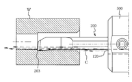
- the coolant is not supplied from the outside, but the channel is provided in the holder itself along the direction in which the axial hole extends. In some cases, this flow path is opened at the tip end face of the holder to form a jet port (discharge port) (Patent Document 1). As shown in FIG.
- the spout 120 is positioned on the cutting edge 203 side (flank side) of the boring bar 200 inserted and fixed in the shaft hole 110 of the holder 500.
- the coolant (shown by broken line) C is jetted (sprayed) in a jet stream form from the jet port 120 at a high pressure to be poured (sprayed) onto the cutting edge 203.
- the coolant means a fluid (cutting fluid or gas) exposed to the cutting portion for the purpose of lubrication between the cutting edge (cutting edge) 203 and the work, cooling of both (preventing temperature rise), etc. .
- the internal diameter processing of such a blind hole can enhance chip dischargeability.
- an opening is made on the side opposite to the cutting edge (back side) rather than the cutting edge side (a flank surface)).
- the coolant C is jetted from the jet nozzle 120 provided on the opposite side to the cutting edge 203 toward the back of the blind hole, so to speak, so to speak a U-turn at the back of the hole.
- the chips generated on the side of the cutting edge 203 are discharged to the inlet side of the blind hole together with the coolant C along the gap such as the chip discharging groove provided on the side of the cutting edge 203.
- the method of supplying the coolant on the side of the cutting edge 203 is also referred to as “cutting edge supply”, and as shown in FIG.
- the supply system to supply is also referred to as "backside supply”.
- the screw hole 135 into which the setscrew 130 for fixing the boring bar 200 is screwed is provided on one side surface of the outer peripheral face forming the shank portion of the boring bar 200 (see FIG. 11, see FIG. 12).
- the pressing for fixing the boring bar 200 by the set screw 130 is performed in the same direction as facing the rake surface 205 of the cutting edge 203. If this pressing state is used, the main component of cutting resistance can be received not by the pressure support by the point support of the set screw 130 but by the inner peripheral surface of the shaft hole 110, so the cutting blade 203 has high stability. Is obtained.
- the pressing surface of the boring bar 200 is the same direction as facing the rake surface 205 of the cutting edge 203.
- a hole into which the set screw 130 is screwed is provided on the same side as facing the rake surface 205 of the cutting blade 203 in the cutting edge supply.
- the setup operation including the screwing operation of such a set screw 130 etc.
- it is a screwing operation by looking down from the upper surface side of the holder 500 so that the operator can visually check the set screw 130 etc. Is set to be fixed to the tool rest H.
- the holder 500 is rotated 180 degrees in the mounting hole of the tool base H, so screwing operation of the set screw 130 is a screwing operation from the lower surface of the holder 500 turn into. Therefore, there is also a problem that the workability becomes worse. If internal diameter processing is performed by rotating the boring bar 200 by 180 degrees and arranging it in the opposite direction (so-called reverse cutting tool) without rotating the holder 500, such screwing work The problem is gone.
- the present invention has been made in view of the problems in the cutting tool for internal diameter processing described above, and does not cause problems in fixing the boring bar, and moreover, the positions of the jet ports such as cutting edge supply and back supply of coolant. Its purpose is to make it possible to deal with the differences in one holder.
- the invention according to claim 1 is an axial hole into which a boring bar having a cutting edge on one side of a tip can be inserted, and one or more for fixing the inserted boring bar by screwing a set screw.
- a holder for a cutting tool having a screw hole formed on one side of the outer peripheral surface of the holder and penetrating toward the shaft hole,
- a cutting tool having a jet port formed at its tip end face so as to eject coolant toward the tip of the boring bar which is inserted into the shaft hole and fixed by screwing of the set screw.
- a screw hole for fixing the inserted boring bar by screwing in a set screw penetrates from the outer peripheral surface toward the shaft hole It is characterized in that it is provided.
- the jet outlet when the holder for a cutting tool is viewed from the tip surface, the jet outlet is drawn so as to be perpendicular to the center line of the screw hole and pass through the center of the shaft hole. It is provided so that it may exist on a straight line, It is a holder for cutting tools of Claim 1 characterized by the above-mentioned.
- the jet outlet when the holder for a cutting tool is viewed from the tip surface, the jet outlet is drawn so as to be perpendicular to the center line of the screw hole and pass through the center of the shaft hole. It is provided so that it may not exist on a straight line, It is a holder for cutting tools of Claim 1 characterized by the above-mentioned.
- the invention according to claim 4 is characterized in that the jet nozzle is formed by being recessed in the inner peripheral surface of the shaft hole in the tip end surface and opened. It is a holder for cutting tools given in a paragraph.
- the jet nozzle is provided in the tip end surface of the tip end surface through a flow path provided in the holder for the cutting tool without communicating with the shaft hole.
- the invention according to claim 6 is the cutting tool holder according to any one of claims 1 to 5, characterized in that the set screw is screwed into all the screw holes. is there.
- the boring bar is inserted into the shaft hole of the holder for a cutting tool according to claim 6, and the boring bar is the same surface as the rake face of the set screw.
- the cutting tool is fixed by screwing in a set screw which is screwed into a screw hole in a position to hold down the.
- the above configuration does not cause significant complication of the structure, and is used for fixing the boring bar by the setscrew in both of the edge feed and the back feed.
- the pressing can be performed in the same direction as the direction in which the rake face of the cutting edge faces. For this reason, as in the conventional case, it is not necessary to arrange two kinds of holders having different screw hole positions so as to be able to cope with the wrong position of the coolant outlet, and therefore, in the stock of cutting tools and their management.
- the jet outlet is opened at the tip end face of the holder itself, but it is sufficient if selection between cutting edge feed and back face feed can be made. Therefore, among the tip faces of the jet tip itself, Although it is sufficient for one side to be open at one side of the shaft hole, a plurality of holes may be opened.
- the jet nozzle when the holder is viewed from the front end surface, the jet nozzle is perpendicular to the center line of the screw hole and drawn on a straight line drawn so as to pass through the center of the shaft hole.
- the jet nozzle is provided so that its center exists, but when the holder is viewed from the end face, the jet outlet is perpendicular to the center line of the screw hole, as described in claim 3. It may be provided not to be on a straight line drawn so as to pass through the center of the shaft hole.
- the jet nozzle may be recessed on the inner peripheral surface of the shaft hole as described in claim 4 or, as described in claim 5, it may be independent from the shaft hole. You may provide as a hole.
- it since it can be recessed so as to cut in the inner peripheral surface of the shaft hole, its formation is easy, the diameter of the hole is small, and its inner peripheral surface and boring bar Coolant can be effectively supplied even when the gap with the outer peripheral surface is small.
- the coolant may flow into the gap between the inner peripheral surface of the shaft hole and the outer peripheral surface of the boring bar, or it may leak through the screwing surface of the set screw, etc. There is a challenge on the On the other hand, in the invention according to claim 5, such a problem can be solved.
- the set screw is screwed into all of the screw holes. This is because, in this way, the setscrew is less likely to be dissipated or lost, and the cutting tool can quickly respond to either a cutting edge supply or a back surface supply.
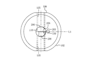
- the enlarged view of the front end surface of the holder of FIG. The S4-S4 sectional view of the holder of FIG.
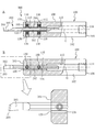
- the disassembled perspective view of the cutting tool containing the holder of FIG. A is a cross-sectional view of a cutting tool formed by inserting a boring bar into the holder of FIG. 1 and fixed by “feed edge”, B is a view seen from the rake surface side passing through the axis, and an enlarged view of the main part.
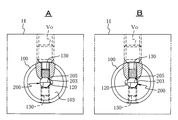
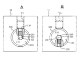
- Fig. 5A is a partially cutaway view as viewed from the tip side when the cutting tool of "edge supply” in Fig. 5 is fixed to the tool post;
- Fig. 7B is a partially broken view when "backward supply” is made in A;
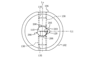
- the figure explaining the other example which changed the jet nozzle in FIG. The figure explaining the other example which changed the jet nozzle in FIG.
- the perspective view for description which shows an example of the conventional cutting tool for internal diameter processing, and its principal part enlarged view.
- A is a partially cutaway view seen from the tip side of the state in which the cutting tool of FIG. 11 is fixed to the tool post with “cutting edge supply”, and B is “backward supplying” from “cutting edge supply” in A Figure of time.
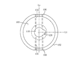
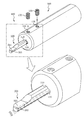
- 100 is a holder, and in a round bar (cylindrical body), a central axis G thereof coaxially has a hole having an inner circumferential surface whose cross section is a circle.
- the shaft hole 110 for inserting the boring bar is taken as the shaft hole 110 for inserting the boring bar from the front end surface 103 of the holder 100 to the middle toward the rear end (surface) 105
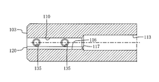
- Up to 105 are flow channels 113 for supplying coolant, which have a diameter larger than this shaft hole 110.
- a screw (a pipe taper screw) 114 is provided at an end portion of the inner peripheral surface of the flow path 113 that opens to the rear end surface 105 of the holder 100 as a pipe connection portion for supplying the coolant.
- flat surfaces (flat surfaces) 106 having a constant width are formed identically on both side surfaces in parallel with each other and extending forward and backward. And in this example, fixation is carried out toward the axial hole 110 in the diametrical direction of the holder 100 in the region corresponding to the axial hole 110 which is the tip surface 103 side of the holder 100 in the plane 106.
- a screw hole 135 is provided for screwing a setscrew 130 for the screw.
- a total of four places of two places are provided at intervals in the front and back in each side face, and a set screw 130 (for example, a hexagonal set set screw 130) can be screwed in each screw hole 135 It is set to.
- the flat surface 106 is a surface which can be pressed by screwing in a fixing bolt after the cutting tool including the holder 100 is inserted into the mounting hole of the tool post of the lathe. That is, the holder 100 has a cross section that can rotate in a sliding contact state in a circular cross-sectional mounting (hole) in the tool post of the lathe, and the rotation is stopped when the holder 100 is fixed. It is done.
- the shaft hole 110 has a cutting edge 203 on one side of each end like the boring bar 200 shown as the lower view in FIG. 4 and a circular hole into which an intermediate portion (shank portion) 207 can be inserted. It is assumed.
- the boring bar 200 shown in FIG. 4 is provided with a rake face 205 on the mutually opposing side surfaces.
- the inner diameter of the shaft hole 110 is sized to rotate the middle portion 207 in a sliding contact state with a minute gap around the axis. In this example, when the holder 100 is viewed from the tip end surface 103 side (see FIG.
- the recessed groove 116 is provided vertically on a straight line L1 drawn to pass through the center of the shaft hole 110. And this ditch
- groove 116 is extended forward and backward over the full length of the axial hole 110 (refer each cross-sectional view of FIG. 1, and FIG. 3). Further, when the holder 100 is viewed from the distal end surface 103, that is, when cut in a cross section perpendicular to the axis G of the shaft hole 110, the recessed groove 116 has an arc shape (crescent shape) that is concave.
- the center in the groove width direction of the recessed groove 116 is provided on the straight line L1.
- the center of the concave groove 116 in the groove width direction may not be present on the straight line L1.
- the rear end 117 of the recessed groove 116 is connected to the rear coolant supply flow path 113, and the front end thereof is opened at the front end surface 103 of the holder 100 to form the jet port 120.
- a predetermined boring bar 200 corresponding to the diameter of the shaft hole 110 as shown in the lower part of FIG. 4 is inserted into the shaft hole 110 by a predetermined amount.
- the intermediate portion (shank portion) 207 the surface in the same direction as the rake surface 205 of the cutting edge 203 is held down by a set screw 130 screwed into the screw hole 135 and fixed.
- the cutting tool 300 for internal diameter processing shown in FIGS. 5 and 6 is obtained.
- a cutting tool of “cutting edge supply” as shown in FIG.
- the cutting edge 203 on one side of the tip of the boring bar 200 when viewed from the tip surface 103 of the holder 100 It becomes the jet port 120 side of the coolant. Therefore, in this case, the set screw 130 (FIG. 5-A, the set screw 130 on FIG. 6) on the same side as the surface to which the rake surface 205 faces is screwed with a predetermined torque. Just do it. Prior to this screwing, the set screw 130 on the opposite side may be properly screwed off so that the tip thereof does not protrude to the inner peripheral surface of the shaft hole 110.
- the rake face 205 can be grasped at an intermediate portion 207 (shank portion) of the boring bar 200 fixed by the set screw 130, and the fixation by the set screw 130 can be stably performed without rotating.
- a flat surface 206 which extends forward and backward with a predetermined width is provided in the same direction as the surface to which the rake surface 205 faces.
- the flat surface 206 since the illustrated boring bar 200 is of the type having the cutting edges 203 on different sides from each other as described above, the flat surface 206 has a circular cross-section base as in the holder 100. As, it is mutually provided in parallel mutually on the both surfaces of the outer peripheral surface.
- the coolant supply piping is connected to the connection portion (pipe screw) 114 of the rear end 105 of the flow path 113 for coolant supply on the rear end surface 105 of the holder 100 ) Is supplied at a high pressure, the coolant is jetted from the jet nozzle 120 opened at the front end surface 103 of the holder 100 toward the cutting edge 203 as a jet flow.
- the cutting tool 300 of this embodiment as shown in FIG. 7A, the cutting tool 300 is inserted into the mounting hole of the tool post H of a predetermined lathe with the rake face 205 up and the fixing bolt Vo
- desired internal diameter processing internal diameter processing of a through hole
- the fixing bolt Vo fixing 100 and all set screws 130 screwed into the holder 100 are screwed back and loosened, for example, while holding the boring bar 200 in the same posture while boring the holder 100. Flip around the bar 200 (180 degrees). By doing this, as shown in FIG. 7-B, the spout 120 comes to the “back feed” position. Therefore, by screwing in the setscrew 130 and screwing in the fixing bolt Vo at the position in the same manner as described above, it is possible to carry out the inner diameter processing in the back surface supply.
- the coolant spout 120 is positioned on the opposite side to the cutting edge 203 side.
- the set screw 130 which was on the rake surface 205 side of the boring bar 200 and did not play the role of fixation before this inversion was fixed on the rake surface 205 in the same direction as the rake surface before inversion. It comes in the same position as the screw 130. Therefore, the boring bar 200 can be re-clamped by screwing in the set screw 130, which had been fixed before turning, again.
- the holder 100 even in the usage mode of the back surface feeding, the instability of the fixation of the boring bar 200 by the set screw 130 does not occur, and the screwing operation is the same as before. Since the operator can look down from above, the work can be simplified and speeded up for the operator. As a matter of course, the same can be applied to the case of further returning to the cutting edge supply after this.
- the changing operation between the cutting edge supply and the back surface supply can be performed with the cutting tool 300 removed from the tool post H, but it is apparent that the same effect can be obtained in that case as well.
- the jet nozzle 120 is provided recessed in the inner peripheral surface of the shaft hole 110 and its shape is an arc shape (crescent moon shape), both in blade edge supply and back surface supply,
- the coolant can be efficiently supplied to the tip of the boring bar 200 so as to be along the tip of the boring bar 200 and also when the gap with the inner circumferential surface of the processing hole is small.
- the flow passage cross section is not limited to the circular arc shape (crescent moon shape), but has an appropriate cross sectional shape such as rectangular. It can also be done.
- the supply from the pressure source (pump) of the coolant is A connection port (screwed-in portion) of the supply pipe is provided at, for example, a portion near the tip of the outer peripheral surface 102 of the holder 100 that does not interfere with fixing to the tool rest, and a flow channel 113 is provided It can also be done.
- the spout 120 is opened at a position slightly separated from the shaft hole 110 at the tip end surface 103 of the holder 100, and a flow path provided without communicating with the shaft hole 110. It may be provided as an independent hole (not shown). That is, in this case, a channel for coolant supply is separately formed in the form of a tunnel in the holder 100 separately from the shaft hole 110 so as to be continuous with the jet port 120, and the coolant is supplied from the pressure source.
- a connection port may be provided on the rear end surface 105 or the outer peripheral surface of the holder 100.
- the coolant can be jetted out of the jet nozzle 120 as an independent jet flow, so that, for example, the screwing surface of the set screw 130 (a screw of the screw hole 135 and the set screw It is possible to avoid problems such as leakage of coolant from a gap with a 130 screw or the like. Even if the hole to be machined has a small diameter, it is effective for relatively large holes.
- the cutting tool holder 100 in the above example is based on a round bar having a circular cross section and provided with the flat surfaces 106 parallel to each other on the outer peripheral surface, but the outer peripheral surface shape of the cutting tool holder 100 itself is It can be appropriate.
- the outer peripheral surface may be, for example, smaller in diameter than the other portion (attachment portion to the tool post) which is located behind the tip end surface 103 and which is closer to the tip end.
- the axial hole 110 can select the position of the spout 120 according to the boring bar, whether the cutting edge supply or the back surface supply, so the cross sectional shape of the axial hole 110 is not limited to a circle. .
- the center in the groove width direction of the recessed groove 116 connected to the spout 120 is for screwing the set screw 130.
- the screw hole 135 is perpendicular to the axis (center line) Ls of the screw hole 135 and on a straight line L1 drawn through the center of the shaft hole 110, but this position is as follows: You can change it. That is, in the above example, when the holder 100 is viewed from the tip end surface 103 side (see FIGS.
- the jet outlet 120 is perpendicular to the axis (center line) Ls of the screw hole 135 and the shaft hole 110
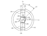
- the jet 120 is perpendicular to the axis (center line) Ls of the screw hole 135, as illustrated in FIG. It may not be on the straight line L1 drawn so as to pass through the center of the axial hole 110.
- the center of the groove 120 in the groove width direction of the spout 120 and the concave groove 116 has an inclination angle ⁇ (for example 45) at the axis (center line) Ls of the screw hole 135 when the holder 100 is viewed from the tip surface 103 side.
- ⁇ for example 45
- the spout 120 is perpendicular to the axis (center line) Ls of the screw hole 135 and is It does not exist on the straight line L1 drawn so as to pass through the center.
- cutting edge supply in this case, although it is “cutting edge supply”, for example, due to the positional relationship between the spout 120 and the boring bar 200 that is fixed,
- the case where coolant is supplied to the cutting edge 203 is shown as the “cutting edge supply” closer to the rake face 205.
- the jet nozzle 120 is described as being recessed on the inner peripheral surface of the shaft hole 110 and the shape is an arc shape (crescent moon shape), but this is shown in FIG. As in the case of the jet nozzle 120, the same applies to the case where the tip surface 103 of the holder 100 is opened independently at a position separated from the shaft hole 110.
- either the “feed on the blade edge” or the “feed on the back surface” should be performed.
- the spout 120 when viewed from the front end surface 103 of the holder 100, either the “feed on the blade edge” or the “feed on the back surface” should be performed.
- the spout 120 when viewed from the front end surface 103 of the holder 100, either the “feed on the blade edge” or the “feed on the back surface” should be performed.
- the spout 120 when viewed from the front end surface 103 of the holder 100, either the “feed on the blade edge” or the “feed on the back surface” should be performed.
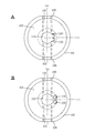
- FIG. 10A even when the spout 120 is recessed on the inner peripheral surface of the shaft hole 110, it may be two spouts 120 divided into two or more. Further, as shown in FIG. 10-B, the same is true even when the spout 120 is an independent hole.
- the two split jets (two jets) 120 are located at the center line Ls of the screw hole 135 when the holder is viewed from the end face 103. Since it is vertical and straddles a straight line L1 drawn to pass through the center of the axial hole 110, it does not exist on the straight line L1.
- the two split jets (two jets) 120 are located at the center line Ls of the screw hole 135 when the holder is viewed from the end face 103. Since it is vertical and straddles a straight line L1 drawn to pass through the center of the axial hole 110, it does not exist on the straight line L1.
- any one of the two divided jet nozzles (two jet nozzles) 120 is provided in the presence (overlap) arrangement on the straight line L1. It is clear that it is also good.
- the jet nozzle may consist of three or more things.
- the holder in fixing the boring bar, can be fixed with a set screw in the same direction as the fixed part faces the rake side, and moreover, "edge supply” and “back supply” of the coolant.
- the holder in fixing the boring bar, fixing by the setscrew is “a face that faces the rake face” means not only a face parallel to the rake face, but also faces that are not parallel to the rake face and have an inclined angle It contains.
Landscapes
- Engineering & Computer Science (AREA)
- Mechanical Engineering (AREA)
- Cutting Tools, Boring Holders, And Turrets (AREA)
- Auxiliary Devices For Machine Tools (AREA)
Abstract
Priority Applications (4)
| Application Number | Priority Date | Filing Date | Title |
|---|---|---|---|
| EP14853437.3A EP3059035A4 (fr) | 2013-10-18 | 2014-09-22 | Support d'outil de coupe et outil de coupe |
| CN201480057384.9A CN105636726A (zh) | 2013-10-18 | 2014-09-22 | 切削刀具用刀柄及切削刀具 |
| KR1020167009766A KR20160054600A (ko) | 2013-10-18 | 2014-09-22 | 절삭 공구용 홀더 및 절삭 공구 |
| US15/027,745 US20160236282A1 (en) | 2013-10-18 | 2014-09-22 | Cutting tool holder and cutting tool |
Applications Claiming Priority (2)
| Application Number | Priority Date | Filing Date | Title |
|---|---|---|---|
| JP2013-217676 | 2013-10-18 | ||
| JP2013217676A JP2015077669A (ja) | 2013-10-18 | 2013-10-18 | 切削工具用ホルダ及び切削工具 |
Publications (1)
| Publication Number | Publication Date |
|---|---|
| WO2015056406A1 true WO2015056406A1 (fr) | 2015-04-23 |
Family
ID=52827867
Family Applications (1)
| Application Number | Title | Priority Date | Filing Date |
|---|---|---|---|
| PCT/JP2014/004852 WO2015056406A1 (fr) | 2013-10-18 | 2014-09-22 | Support d'outil de coupe et outil de coupe |
Country Status (6)
| Country | Link |
|---|---|
| US (1) | US20160236282A1 (fr) |
| EP (1) | EP3059035A4 (fr) |
| JP (1) | JP2015077669A (fr) |
| KR (1) | KR20160054600A (fr) |
| CN (1) | CN105636726A (fr) |
| WO (1) | WO2015056406A1 (fr) |
Cited By (2)
| Publication number | Priority date | Publication date | Assignee | Title |
|---|---|---|---|---|
| US20150298216A1 (en) * | 2012-10-25 | 2015-10-22 | Utilis Ag | Clamping device with coolant channel, method of producing the clamping device and tool holding plate for a lathe with such a clamping device |
| EP4420814A1 (fr) | 2023-02-22 | 2024-08-28 | Tungaloy Corporation | Outil de coupe |
Families Citing this family (12)
| Publication number | Priority date | Publication date | Assignee | Title |
|---|---|---|---|---|
| JP6035696B1 (ja) * | 2015-12-07 | 2016-11-30 | 株式会社タンガロイ | 切削工具および支持部材 |
| DE102016105354B4 (de) * | 2016-03-22 | 2018-03-22 | Hartmetall-Werkzeugfabrik Paul Horn Gmbh | Spanabhebendes Werkzeug |
| DE102017214155A1 (de) * | 2017-08-14 | 2019-02-14 | MAPAL Fabrik für Präzisionswerkzeuge Dr. Kress KG | Spannfutter |
| CN109129736A (zh) * | 2018-07-23 | 2019-01-04 | 威尔廉(苏州)机械有限公司 | 一种切削加工用刀具及其装夹系统 |
| CN109676512A (zh) * | 2018-11-13 | 2019-04-26 | 江苏科比特科技有限公司 | 一种刀具钝化机用快速装夹刀杆 |
| DE102019001347A1 (de) * | 2019-02-26 | 2020-08-27 | Hubert Kimmich | Vorrichtung zum Befestigen einer Bohrstange |
| CN110773824B (zh) * | 2019-12-06 | 2024-05-31 | 山东蓬翔汽车有限公司 | 一种防脱落加长刀具 |
| US11819928B2 (en) | 2020-10-14 | 2023-11-21 | Iscar, Ltd. | Insert holder having insert receiving recess with insert orientation projection and cutting tool |
| DE102020134531A1 (de) * | 2020-12-22 | 2022-06-23 | Hubert Kimmich | Bohrstangenanordnung |
| CN113843901B (zh) * | 2021-09-15 | 2023-12-29 | 浙江富乐德石英科技有限公司 | 一种石英环类产品加工方法 |
| TWI842065B (zh) * | 2022-08-18 | 2024-05-11 | 益壯企業有限公司 | 具冷卻出水的切削工具 |
| CN117245114A (zh) * | 2023-06-30 | 2023-12-19 | 北京新风航天装备有限公司 | 一种狭小空间精密同轴孔加工装置及方法 |
Citations (7)
| Publication number | Priority date | Publication date | Assignee | Title |
|---|---|---|---|---|
| JPS54138183U (fr) * | 1978-03-20 | 1979-09-25 | ||
| JPH0585535U (ja) | 1992-04-20 | 1993-11-19 | 株式会社日研工作所 | 工具ホルダー |
| JPH0657502U (ja) * | 1992-07-29 | 1994-08-09 | 京セラ株式会社 | 切削工具 |
| JP2007185765A (ja) | 2006-01-10 | 2007-07-26 | Sandvik Intellectual Property Ab | 内径旋削用のボーリングバー |
| JP2007525334A (ja) * | 2004-03-01 | 2007-09-06 | ソシエテ・コメルシヤル・リユシユ | 旋盤工具 |
| JP2010240817A (ja) * | 2009-04-01 | 2010-10-28 | Yukiji Boku | ボーリングバイト用ホルダー&スリーブ |
| US20100322722A1 (en) * | 2008-02-04 | 2010-12-23 | Ying-Fan Enterprise Co., Ltd. | Combined-Type Lathe Tool |
Family Cites Families (1)
| Publication number | Priority date | Publication date | Assignee | Title |
|---|---|---|---|---|
| US7357607B2 (en) * | 2003-08-07 | 2008-04-15 | Pv Engineering & Mfg., Inc. | Tool holder |
-
2013
- 2013-10-18 JP JP2013217676A patent/JP2015077669A/ja active Pending
-
2014
- 2014-09-22 US US15/027,745 patent/US20160236282A1/en not_active Abandoned
- 2014-09-22 KR KR1020167009766A patent/KR20160054600A/ko not_active Application Discontinuation
- 2014-09-22 WO PCT/JP2014/004852 patent/WO2015056406A1/fr active Application Filing
- 2014-09-22 EP EP14853437.3A patent/EP3059035A4/fr not_active Withdrawn
- 2014-09-22 CN CN201480057384.9A patent/CN105636726A/zh active Pending
Patent Citations (7)
| Publication number | Priority date | Publication date | Assignee | Title |
|---|---|---|---|---|
| JPS54138183U (fr) * | 1978-03-20 | 1979-09-25 | ||
| JPH0585535U (ja) | 1992-04-20 | 1993-11-19 | 株式会社日研工作所 | 工具ホルダー |
| JPH0657502U (ja) * | 1992-07-29 | 1994-08-09 | 京セラ株式会社 | 切削工具 |
| JP2007525334A (ja) * | 2004-03-01 | 2007-09-06 | ソシエテ・コメルシヤル・リユシユ | 旋盤工具 |
| JP2007185765A (ja) | 2006-01-10 | 2007-07-26 | Sandvik Intellectual Property Ab | 内径旋削用のボーリングバー |
| US20100322722A1 (en) * | 2008-02-04 | 2010-12-23 | Ying-Fan Enterprise Co., Ltd. | Combined-Type Lathe Tool |
| JP2010240817A (ja) * | 2009-04-01 | 2010-10-28 | Yukiji Boku | ボーリングバイト用ホルダー&スリーブ |
Non-Patent Citations (1)
| Title |
|---|
| See also references of EP3059035A4 |
Cited By (3)
| Publication number | Priority date | Publication date | Assignee | Title |
|---|---|---|---|---|
| US20150298216A1 (en) * | 2012-10-25 | 2015-10-22 | Utilis Ag | Clamping device with coolant channel, method of producing the clamping device and tool holding plate for a lathe with such a clamping device |
| US10022804B2 (en) * | 2012-10-25 | 2018-07-17 | Utilis Ag | Clamping device with coolant channel, method of producing the clamping device and tool holding plate for a lathe with such a clamping device |
| EP4420814A1 (fr) | 2023-02-22 | 2024-08-28 | Tungaloy Corporation | Outil de coupe |
Also Published As
| Publication number | Publication date |
|---|---|
| EP3059035A4 (fr) | 2017-05-24 |
| EP3059035A1 (fr) | 2016-08-24 |
| KR20160054600A (ko) | 2016-05-16 |
| CN105636726A (zh) | 2016-06-01 |
| US20160236282A1 (en) | 2016-08-18 |
| JP2015077669A (ja) | 2015-04-23 |
Similar Documents
| Publication | Publication Date | Title |
|---|---|---|
| WO2015056406A1 (fr) | Support d'outil de coupe et outil de coupe | |
| KR101779621B1 (ko) | 밀링 공구 | |
| KR101749784B1 (ko) | 조정가능한 냉각 기구를 갖는 회전식 절삭 공구 | |
| WO2016117461A1 (fr) | Foret | |
| US9931699B2 (en) | Cutting tool holder and cutting tool | |
| US10537943B2 (en) | Modular rotary tool and modular tool system | |
| US8459904B2 (en) | Cutting insert and holder for rotating applications | |
| US20070231097A1 (en) | Cutting Tool and Adaptor | |
| JP2013059853A (ja) | 切削工具 | |
| JP5310191B2 (ja) | インサート着脱式切削工具 | |
| US20090214305A1 (en) | Coolant nozzles for milling cutters | |
| JP2010094748A (ja) | 切削工具 | |
| JP4982253B2 (ja) | コンビネーションホルダ | |
| JP2006289567A (ja) | 工作機械 | |
| JP2010142889A (ja) | 工具保持具、工具保持具用切削液供給プレート及び切削加工方法 | |
| JP4179601B2 (ja) | アーバおよび回転工具 | |
| WO2017126145A1 (fr) | Fraise-mère | |
| JP7494466B2 (ja) | クーラント孔付きスロッティングカッターの取付部材 | |
| JP2511368B2 (ja) | ク―ラント供給方法および装置 | |
| JP2004148429A (ja) | コレットチャック用コレット | |
| JP2008012600A (ja) | ミーリングカッタ用アーバ | |
| JP3054116U (ja) | フライス盤のための洗浄ツール | |
| KR20190060084A (ko) | 공작기계 주축 사이드 절삭유 분사 시스템 | |
| JP2005034954A (ja) | 油穴付き切削工具および切削加工方法 | |
| JP2024123825A (ja) | フランジ付きドリル、及びフランジ付きドリルのホルダ |
Legal Events
| Date | Code | Title | Description |
|---|---|---|---|
| 121 | Ep: the epo has been informed by wipo that ep was designated in this application |
Ref document number: 14853437 Country of ref document: EP Kind code of ref document: A1 |
|
| WWE | Wipo information: entry into national phase |
Ref document number: 15027745 Country of ref document: US |
|
| REEP | Request for entry into the european phase |
Ref document number: 2014853437 Country of ref document: EP |
|
| WWE | Wipo information: entry into national phase |
Ref document number: 2014853437 Country of ref document: EP |
|
| ENP | Entry into the national phase |
Ref document number: 20167009766 Country of ref document: KR Kind code of ref document: A |
|
| NENP | Non-entry into the national phase |
Ref country code: DE |