WO2015053243A1 - 排ガス浄化装置、保持シール材及び保持シール材の製造方法 - Google Patents
排ガス浄化装置、保持シール材及び保持シール材の製造方法 Download PDFInfo
- Publication number
- WO2015053243A1 WO2015053243A1 PCT/JP2014/076749 JP2014076749W WO2015053243A1 WO 2015053243 A1 WO2015053243 A1 WO 2015053243A1 JP 2014076749 W JP2014076749 W JP 2014076749W WO 2015053243 A1 WO2015053243 A1 WO 2015053243A1
- Authority
- WO
- WIPO (PCT)
- Prior art keywords
- cone
- exhaust gas
- heat insulating
- sealing material
- holding
- Prior art date
- Legal status (The legal status is an assumption and is not a legal conclusion. Google has not performed a legal analysis and makes no representation as to the accuracy of the status listed.)
- Ceased
Links
Images





Classifications
-
- F—MECHANICAL ENGINEERING; LIGHTING; HEATING; WEAPONS; BLASTING
- F01—MACHINES OR ENGINES IN GENERAL; ENGINE PLANTS IN GENERAL; STEAM ENGINES
- F01N—GAS-FLOW SILENCERS OR EXHAUST APPARATUS FOR MACHINES OR ENGINES IN GENERAL; GAS-FLOW SILENCERS OR EXHAUST APPARATUS FOR INTERNAL-COMBUSTION ENGINES
- F01N13/00—Exhaust or silencing apparatus characterised by constructional features
- F01N13/18—Construction facilitating manufacture, assembly, or disassembly
- F01N13/1872—Construction facilitating manufacture, assembly, or disassembly the assembly using stamp-formed parts or otherwise deformed sheet-metal
-
- F—MECHANICAL ENGINEERING; LIGHTING; HEATING; WEAPONS; BLASTING
- F01—MACHINES OR ENGINES IN GENERAL; ENGINE PLANTS IN GENERAL; STEAM ENGINES
- F01N—GAS-FLOW SILENCERS OR EXHAUST APPARATUS FOR MACHINES OR ENGINES IN GENERAL; GAS-FLOW SILENCERS OR EXHAUST APPARATUS FOR INTERNAL-COMBUSTION ENGINES
- F01N13/00—Exhaust or silencing apparatus characterised by constructional features
- F01N13/18—Construction facilitating manufacture, assembly, or disassembly
- F01N13/1838—Construction facilitating manufacture, assembly, or disassembly characterised by the type of connection between parts of exhaust or silencing apparatus, e.g. between housing and tubes, between tubes and baffles
- F01N13/1844—Mechanical joints
- F01N13/185—Mechanical joints the connection being realised by deforming housing, tube, baffle, plate, or parts thereof
-
- F—MECHANICAL ENGINEERING; LIGHTING; HEATING; WEAPONS; BLASTING
- F01—MACHINES OR ENGINES IN GENERAL; ENGINE PLANTS IN GENERAL; STEAM ENGINES
- F01N—GAS-FLOW SILENCERS OR EXHAUST APPARATUS FOR MACHINES OR ENGINES IN GENERAL; GAS-FLOW SILENCERS OR EXHAUST APPARATUS FOR INTERNAL-COMBUSTION ENGINES
- F01N3/00—Exhaust or silencing apparatus having means for purifying, rendering innocuous, or otherwise treating exhaust
- F01N3/08—Exhaust or silencing apparatus having means for purifying, rendering innocuous, or otherwise treating exhaust for rendering innocuous
- F01N3/10—Exhaust or silencing apparatus having means for purifying, rendering innocuous, or otherwise treating exhaust for rendering innocuous by thermal or catalytic conversion of noxious components of exhaust
- F01N3/24—Exhaust or silencing apparatus having means for purifying, rendering innocuous, or otherwise treating exhaust for rendering innocuous by thermal or catalytic conversion of noxious components of exhaust characterised by constructional aspects of converting apparatus
- F01N3/28—Construction of catalytic reactors
- F01N3/2839—Arrangements for mounting catalyst support in housing, e.g. with means for compensating thermal expansion or vibration
-
- F—MECHANICAL ENGINEERING; LIGHTING; HEATING; WEAPONS; BLASTING
- F01—MACHINES OR ENGINES IN GENERAL; ENGINE PLANTS IN GENERAL; STEAM ENGINES
- F01N—GAS-FLOW SILENCERS OR EXHAUST APPARATUS FOR MACHINES OR ENGINES IN GENERAL; GAS-FLOW SILENCERS OR EXHAUST APPARATUS FOR INTERNAL-COMBUSTION ENGINES
- F01N3/00—Exhaust or silencing apparatus having means for purifying, rendering innocuous, or otherwise treating exhaust
- F01N3/08—Exhaust or silencing apparatus having means for purifying, rendering innocuous, or otherwise treating exhaust for rendering innocuous
- F01N3/10—Exhaust or silencing apparatus having means for purifying, rendering innocuous, or otherwise treating exhaust for rendering innocuous by thermal or catalytic conversion of noxious components of exhaust
- F01N3/24—Exhaust or silencing apparatus having means for purifying, rendering innocuous, or otherwise treating exhaust for rendering innocuous by thermal or catalytic conversion of noxious components of exhaust characterised by constructional aspects of converting apparatus
- F01N3/28—Construction of catalytic reactors
- F01N3/2839—Arrangements for mounting catalyst support in housing, e.g. with means for compensating thermal expansion or vibration
- F01N3/2853—Arrangements for mounting catalyst support in housing, e.g. with means for compensating thermal expansion or vibration using mats or gaskets between catalyst body and housing
-
- F—MECHANICAL ENGINEERING; LIGHTING; HEATING; WEAPONS; BLASTING
- F01—MACHINES OR ENGINES IN GENERAL; ENGINE PLANTS IN GENERAL; STEAM ENGINES
- F01N—GAS-FLOW SILENCERS OR EXHAUST APPARATUS FOR MACHINES OR ENGINES IN GENERAL; GAS-FLOW SILENCERS OR EXHAUST APPARATUS FOR INTERNAL-COMBUSTION ENGINES
- F01N2350/00—Arrangements for fitting catalyst support or particle filter element in the housing
Definitions
- the present invention relates to an exhaust gas purification device, a holding sealing material, and a method for manufacturing the holding sealing material.
- an exhaust gas purification device in order to purify harmful substances such as harmful gases contained in exhaust gas discharged from an internal combustion engine such as an engine, an exhaust gas purification device has been provided in the exhaust passage (exhaust pipe through which the exhaust gas flows) of the internal combustion engine. ing.
- the exhaust gas purification apparatus has a structure in which a casing is provided in an exhaust passage of an internal combustion engine, and an exhaust gas treatment body is disposed in the casing. Examples of the exhaust gas treating body include a catalyst carrier or a diesel particulate filter (DPF).
- a holding sealing material made of an inorganic fiber aggregate is wound around the exhaust gas treating body and disposed in the casing.
- This holding sealing material prevents the exhaust gas treating body from being damaged by contact with the casing covering the outer periphery due to vibrations or impacts caused by traveling of an automobile or the like, and exhaust gas from between the exhaust gas treating body and the casing. Is disposed mainly for the purpose of preventing leakage.
- the exhaust passage of the internal combustion engine and the temperature of the exhaust gas are temperatures suitable for catalyst activation (hereinafter also referred to as catalyst activation temperature). ) Must be maintained.
- An exhaust gas purification apparatus in which a catalyst is supported on an exhaust gas treating body cannot exhibit a sufficient catalytic action unless the temperature is raised until a predetermined catalyst activation temperature is reached. For this reason, the exhaust gas purification device is required to have a heat retention performance that prevents the temperature of the exhaust gas treating body from being lowered.
- the holding sealing material wound around the exhaust gas treating body is also expected to keep the exhaust gas treating body warm.
- heat radiation from the cone portion located on the exhaust gas inflow side of the exhaust gas purification device may be a problem.
- the holding sealing material and the heat insulating material are separate members when the holding sealing material is wound around the exhaust gas treating body and the heat insulating material is inserted into the double pipe of the cone portion. For this reason, there are many man-hours when assembling the exhaust gas purification device, and workability is poor.
- the method using a three-dimensional molded body is not preferable because the three-dimensional shape is bulky, which is bulky at the time of storage after manufacture of the holding sealing material and at the time of transport, and has low storage and transport efficiency.
- An object of the present invention is to provide an exhaust gas purification device that does not cause a displacement of the heat insulating material in the exhaust gas purification device and has excellent workability in assembling the exhaust gas purification device.
- the present invention is excellent in the heat insulation performance of the exhaust gas treating body and the cone part, can cover both the exhaust gas treating body and the cone member without causing a positional shift, and is a holding sealing material having high storage and transport efficiency. It aims at providing and the manufacturing method of the said holding sealing material.
- an exhaust gas purification apparatus of the present invention comprises an exhaust gas treating body, A cylindrical casing having a first end located on the exhaust gas inflow side and a second end located on the exhaust gas outflow side, and containing the exhaust gas treating body; A first cone member disposed on the first end portion side of the casing, the diameter of which is gradually reduced as the distance from the first end portion of the casing increases; A cylindrical member disposed on the second end portion side of the casing, the second cone member having a diameter that gradually decreases with increasing distance from the second end portion of the casing; An exhaust gas purification apparatus comprising a mat including inorganic fibers, a part of which is wound around the exhaust gas treatment body, and a holding sealing material disposed between the exhaust gas treatment body and the casing.
- the holding sealing material is A holding part wound around the exhaust gas treating body, A first cone heat insulating portion covering at least a part of the inner peripheral surface of the first cone member, The holding portion and the first cone heat insulating portion are characterized in that at least a part of each side surface is continuously connected.
- the holding sealing material includes a holding portion and a first cone heat insulating portion, and the holding portion is wound around the exhaust gas treatment body to keep the exhaust gas treatment body warm.
- a cone heat insulation part covers the inner peripheral surface of the first cone member to keep the first cone member warm. Since the first cone member is located on the exhaust gas inflow side, the temperature of the exhaust gas is high and the temperature needs to be kept high.
- the first cone member is the first cone heat insulation. Since it is covered with the part, the heat radiation from the first cone member can be suppressed.
- the holding part and the first cone heat insulating part are continuously connected, there is no positional displacement, and the holding part and the first cone heat insulating part are made of one member, so that the exhaust gas purification apparatus is assembled. Excellent in properties.
- the number of the first cone heat insulating portions is one.
- the shape of the first cone heat insulating portion is a shape obtained by removing a sector having the same central point and central angle as the sector from the sector and having a small radius, or a crescent shape.
- one cone heat insulating portion can form substantially the same shape as the inner peripheral surface of the first cone member, and covers the inner peripheral surface of the first cone member. be able to.
- the number of the first cone heat insulating portions is two or more. Moreover, as for each shape of the said 1st cone heat insulation part, it is desirable that it is a triangle, a trapezoid, or a fan shape.
- the first cone heat insulating portion has the above shape, two or more cone heat insulating portions can be combined to form a shape substantially the same as the inner peripheral surface of the first cone member. The peripheral surface can be covered.
- the entire inner peripheral surface of the first cone member is covered with the first cone heat insulating portion.
- the entire inner peripheral surface of the first cone member is covered, it is possible to provide an exhaust gas purifying apparatus with further excellent heat insulation performance.
- the central axis of the first cone member is deviated from the central axis of the casing.
- An exhaust gas purification device having an eccentric cone, in which the central axis of the first cone member is offset from the central axis of the casing, is preferable because the space around the exhaust gas purification device can be effectively used when mounted on the vehicle, and the degree of freedom of design increases. .
- a slit is provided in the thickness direction of the holding sealing material at a portion where the holding unit and the first cone heat insulating unit are continuously connected.
- fiber scattering suppression processing is performed on a portion where the surface of the holding portion is exposed to the space in the casing.
- the width of the holding part is larger than the length in the longitudinal direction of the exhaust gas treating body, a part of the surface of the holding part is exposed to the space in the casing.
- fiber scattering suppression treatment such as application of an inorganic binder is performed on this portion because fiber scattering is suppressed during the assembly operation of the exhaust gas purification device and when the exhaust gas purification device is used.
- the surface and / or the side surface of the first cone heat insulating portion be subjected to fiber scattering suppression treatment. It is preferable that fiber scattering suppression processing such as application of an inorganic binder is performed on the above-mentioned portion of the first cone heat insulating portion because fiber scattering is suppressed during the assembly operation of the exhaust gas purification device and when the exhaust gas purification device is used.
- the first inner cone member having a diameter smaller than that of the first cone member and symmetrical to the first cone member is disposed inside the first cone member.
- the first cone heat insulating part is preferably disposed between the first cone member and the first inner cone member. Since it will be in the state where the 1st cone heat insulation part was pinched between the 1st cone member and the 1st inner cone member if it is the above-mentioned composition, the position of the 1st cone heat insulation part is in an exhaust gas purification device. Stabilize. Moreover, since the surface of the 1st cone heat insulation part is covered with the 1st inner cone member, it is preferable also at the point by which the fiber scattering from a 1st cone heat insulation part is suppressed.
- the holding sealing material is A second cone heat insulating portion covering at least a part of the inner peripheral surface of the second cone member; It is desirable that at least a part of the side surfaces of the holding portion and the second cone heat insulating portion are continuously connected.
- the number of the second cone heat insulating portions is one.
- the shape of the second cone heat insulating part is preferably a shape obtained by removing a sector having the same central point and central angle as the sector from the sector and having a small radius, or a crescent shape.
- the number of the second cone heat insulating portions is two or more.
- each shape of the said 2nd cone heat insulation part it is desirable that it is a triangle, trapezoid, or a fan shape.
- a straight pipe member which is a cylindrical member having a constant diameter, is disposed at the end of the second cone member opposite to the casing side.
- the holding sealing material is It further comprises a strip portion covering at least a part of the inner peripheral surface of the straight pipe member, It is desirable that at least a part of each side surface of the second cone heat insulating portion and the strip portion are continuously connected.
- the strip portion is also continuously connected to the second cone heat insulating portion, there is no displacement, and the holding portion, the first cone heat insulating portion, the second cone heat insulating portion, and the strip portion are one member. Therefore, the workability of assembling the exhaust gas purification device is excellent.
- the holding sealing material of the present invention comprises a mat containing inorganic fibers, A substantially rectangular holding portion in plan view having a long side extending in the longitudinal direction and a short side substantially perpendicular to the long side;
- the first holding unit side surface which is one of the long side side surfaces of the holding unit and the second holding unit side surface which is the long side side opposite to the first holding unit side surface,
- a holding sealing material comprising a first cone heat insulating portion that is continuously connected to at least a part of the first holding portion side surface,
- both the exhaust gas treating body and the cone member can be covered with one holding sealing material without causing a positional shift. Further, since it can be flat when stored and transported, it becomes a holding sealing material with high storage and transport efficiency.
- the number of the first cone heat insulating portions is one.
- the shape of the first cone heat insulating portion is a shape obtained by removing a sector having the same central point and central angle as the sector from the sector and having a small radius, or a crescent shape.
- the number of the first cone heat insulating portions is two or more. Moreover, as for each shape of the said 1st cone heat insulation part, it is desirable that it is a triangle, a trapezoid, or a fan shape.
- the first cone heat insulating portion has the above shape, two or more cone heat insulating portions can be combined to form substantially the same shape as the inner peripheral surface of the cone member, covering the inner peripheral surface of the cone member. it can.
- the shape of the first cone heat insulating portion is such that the cone cylindrical portion is formed when the holding sealing material is rolled into a cylindrical shape so that the two short sides of the holding portion are in contact with each other. It is desirable that the central axis of the cylinder is shifted from the central axis of the cylindrical part surrounded by the holding part. With the above configuration, it can be suitably used for an eccentric exhaust gas purification apparatus in which the central axis of the cone member is shifted from the central axis of the casing.
- a slit is provided in a thickness direction of the holding sealing material at a portion where the holding portion and the first cone heat insulating portion are continuously connected.
- fiber scattering suppression processing may be performed in the vicinity of a portion of the surface of the holding portion where the holding portion and the first cone heat insulating portion are continuously connected. desirable.
- the vicinity of the part where the holding part and the first cone heat insulating part are continuously connected may be exposed to the space in the casing. It is preferable that fiber scattering suppression treatment such as application of an inorganic binder is performed on this portion because fiber scattering is suppressed during the assembly operation of the exhaust gas purification device and when the exhaust gas purification device is used.
- the surface and / or side surface of the first cone heat insulating portion be subjected to fiber scattering suppression treatment. It is preferable that fiber scattering suppression processing such as application of an inorganic binder is performed on the above-mentioned portion of the first cone heat insulating portion because fiber scattering is suppressed during the assembly operation of the exhaust gas purification device and when the exhaust gas purification device is used.
- the holding sealing material of the present invention further includes a second cone heat insulating portion that is continuously connected to at least a part of the side surface of the second holding portion.
- the number of the second cone heat insulating portions is one.
- the shape of the second cone heat insulating part is preferably a shape obtained by removing a sector having the same central point and central angle as the sector from the sector and having a small radius, or a crescent shape.
- the number of the second cone heat insulating portions is two or more. Moreover, as for each shape of the said 2nd cone heat insulation part, it is desirable that it is a triangle, trapezoid, or a fan shape.
- the holding sealing material of the present invention is a strip portion having a substantially rectangular shape in plan view, continuously connected on the side surface located on the opposite side of the side surface connected to the holding portion among the side surfaces of the second cone heat insulating portion. It is desirable to further include. With the above configuration, the inner peripheral surface of the straight pipe member positioned further on the exhaust gas outflow side from the second cone member can be covered with the strip portion without causing a positional shift. Moreover, since the holding part, the first cone heat insulating part, the second cone heat insulating part, and the strip part are made of one member, the workability of assembling the exhaust gas purification apparatus is excellent.
- the manufacturing method of the holding sealing material of the present invention is a manufacturing method of the holding sealing material of the present invention, A step of punching the holding sealing material from one sheet so as to be in a state where all the parts constituting the holding sealing material are connected is characterized. With the above method, a holding sealing material that can cover both the exhaust gas treating body and the cone member can be manufactured by a simple method.
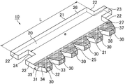
- FIG. 1 is a perspective view schematically showing an example of the holding sealing material of the present invention.
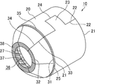
- FIG. 2 is a perspective view schematically showing an example of a state where the holding sealing material is rolled into a cylindrical shape so that two short sides of the holding portion of the holding sealing material shown in FIG. 1 are in contact with each other.
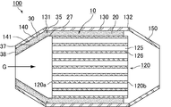
- FIG. 3 is a cross-sectional view schematically showing an example of the exhaust gas purifying apparatus of the present invention.
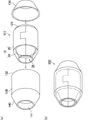
- FIG. 4A is a perspective view schematically showing how the exhaust gas purification apparatus shown in FIG. 3 is assembled
- FIG. 4B is a perspective view schematically showing the assembled exhaust gas purification apparatus.
- FIG. 5 is a top view schematically showing another example of the holding sealing material of the present invention.
- FIG. 6 is a top view schematically showing another example of the holding sealing material of the present invention.
- 7 (a) and 7 (b) are top views schematically showing another example of the holding sealing material of the present invention.
- FIG. 8 is a cross-sectional view schematically showing an example of an exhaust gas purifying apparatus having an eccentric cone.
- FIG. 9 is a top view schematically showing another example of the holding sealing material of the present invention.
- 10 (a) and 10 (b) are top views schematically showing another example of the holding sealing material of the present invention.
- FIG. 11 is a cross-sectional view schematically showing an example of an exhaust gas purifying apparatus having a first inner cone member.
- FIG. 12 is a top view schematically showing an example of the holding sealing material of the present invention including the second cone heat insulating portion.
- FIG. 13A is a cross-sectional view schematically showing an example of the exhaust gas purification apparatus of the present invention in which the inner peripheral surface of the second cone member is covered with the second cone heat insulating portion
- FIG. ) Is a cross-sectional view schematically showing an example of an exhaust gas purification apparatus provided with a first inner cone member and a second inner cone member.
- FIG. 14 is a top view schematically showing an example of the holding sealing material of the present invention having a strip portion.
- FIG. 15 is a cross-sectional view schematically showing an example of the exhaust gas purifying apparatus of the present invention in which the inner peripheral surface of the straight pipe member is covered with a strip portion.
- FIG. 16 is a cross-sectional view schematically showing an example of the exhaust gas purifying apparatus of the present invention having a second inner cone member and an inner straight pipe member.
- FIG. 17 is a top view schematically showing an example of the holding sealing material of the present invention in which another cone heat insulating portion and another holding portion are connected to the strip portion.
- FIG. 18 is a cross-sectional view schematically showing an example of the exhaust gas purifying apparatus of the present invention having two exhaust gas treating bodies.
- the exhaust gas purifying apparatus of the present invention and the holding sealing material of the present invention will be specifically described.
- the present invention is not limited to the following configurations, and can be applied with appropriate modifications without departing from the scope of the present invention.
- the present invention also includes a combination of two or more desirable configurations of the present invention described below.
- the exhaust gas purification apparatus of the present invention includes an exhaust gas treatment body, A cylindrical casing having a first end located on the exhaust gas inflow side and a second end located on the exhaust gas outflow side, and containing the exhaust gas treating body; A first cone member disposed on the first end portion side of the casing, the diameter of which is gradually reduced as the distance from the first end portion of the casing increases; A cylindrical member disposed on the second end portion side of the casing, the second cone member having a diameter that gradually decreases with increasing distance from the second end portion of the casing; An exhaust gas purification apparatus comprising a mat including inorganic fibers, a part of which is wound around the exhaust gas treatment body, and a holding sealing material disposed between the exhaust gas treatment body and the casing.
- the holding sealing material is A holding part wound around the exhaust gas treating body, A first cone heat insulating portion covering at least a part of the inner peripheral surface of the first cone member, The holding portion and the first cone heat insulating portion are characterized in that at least a part of each side surface is continuously connected.
- FIG. 1 is a perspective view schematically showing an example of the holding sealing material of the present invention.
- the holding sealing material shown in FIG. 1 is a holding sealing material that can be used in the exhaust gas purification apparatus of the present invention.
- a holding sealing material 10 shown in FIG. 1 includes a long side 21 extending in a longitudinal direction (a direction indicated by a double arrow a in FIG. 1) and a substantially rectangular holding portion having a short side 22 substantially perpendicular to the long side 21 in plan view. 20 On one short side 22, a convex portion 23 and a concave portion 24 are formed.
- the convex portion 23 and the concave portion 24 are shaped so as to be fitted to each other when the holding portion is wound around the exhaust gas treatment body in order to assemble the exhaust gas purifying device described later.
- the substantially rectangular shape in plan view as the shape of the holding portion 20 means that the shape of the holding portion 20 is rectangular when the shape of the entire holding portion is viewed without considering the shapes of the convex portions and the concave portions. Since the convex part 23 and the concave part 24 are formed on the short side 22, the short side 22 is not a side consisting of a single straight line, but when the holding sealing material is viewed in plan, the short side 22 becomes the long side 21. It can be said that the sides are almost perpendicular.
- the length of the holding sealing material is determined as the length of the long side.
- the length of the long side is a length determined by ignoring the shapes of the convex portion and the concave portion, and is a length determined by a double-headed arrow L in FIG.
- Two side surfaces of the holding unit 20 on the long side 21 side are a first holding unit side surface 25 and a second holding unit side surface 26.
- the first cone heat insulating portion 30 is continuously connected to the first holding portion side surface 25.
- the number of the first cone heat insulating portions may be one or two or more.
- a plurality of (six) first cone heat insulation portions 30 are provided, and each shape of the first cone heat insulation portion 30 is a trapezoid.
- the trapezoidal shape corresponds to one leg of the trapezoid, with the side connected to the first holding unit side surface 25 being a long base 31 and the side away from the first holding unit side 25 being a short base 32.
- the shape has a side 33 and a side 34 corresponding to the other leg.
- the shape of the cone heat insulating portion means a shape when the cone heat insulating portion is viewed in plan.
- the holding sealing material of the present invention since the first cone heat insulating portion and the holding portion are continuously connected, they are usually the same material and are mat-like members having the same thickness.
- a slit 35 is provided in the thickness direction of the holding sealing material 10 at a portion where the holding portion 20 of the holding sealing material 10 and the first cone heat insulating portion 30 are continuously connected.
- the slit 35 is a cut provided to facilitate folding of the cone heat insulating portion when the holding sealing material is rolled into a cylindrical shape to bend the cone heat insulating portion.
- the depth of the slit is preferably 20 to 80% of the thickness of the holding sealing material.
- fiber scattering suppression processing is performed in the vicinity of a portion where the holding portion and the first cone heat insulating portion are continuously connected on the surface of the holding portion.
- a fiber scattering suppression processing unit 27 that has been subjected to fiber scattering suppression processing is shown with hatching.
- the fiber scattering suppression processing unit 27 is desirably provided at a portion where the surface of the holding unit 20 is exposed to the space in the casing when the holding unit 20 is wound around the exhaust gas treatment body and disposed in the exhaust gas purification device.
- FIG. 1 a fiber scattering suppression processing unit 27 that has been subjected to fiber scattering suppression processing is shown with hatching.
- the fiber scattering suppression processing unit 27 is desirably provided at a portion where the surface of the holding unit 20 is exposed to the space in the casing when the holding unit 20 is wound around the exhaust gas treatment body and disposed in the exhaust gas purification device
- the fiber scattering suppression processing unit 37 that is subjected to fiber scattering suppression processing on the surface of the first cone thermal insulation unit 30 and the fiber scattering that is subjected to fiber scattering suppression processing on the side surface of the first cone thermal insulation unit 30.
- the suppression processing unit 38 is shown with hatching.
- Examples of the fiber scattering suppression treatment include a treatment such as coating of the holding binder with an inorganic binder (alumina sol, silica sol). By performing the fiber scattering suppression treatment, erosion of inorganic fibers can be prevented.
- the holding sealing material of the present invention is made of a mat containing inorganic fibers.
- the inorganic fibers constituting the mat are not particularly limited, and may be alumina-silica fibers, alumina fibers, silica fibers, or the like. Moreover, glass fiber and biosoluble fiber may be sufficient. What is necessary is just to change according to the characteristics requested
- low crystalline alumina inorganic fibers are desirable, and low crystalline alumina inorganic fibers having a mullite composition are more desirable.
- inorganic fibers containing a spinel compound are more preferable.
- a highly crystalline alumina material is hard and brittle, so it is not suitable for a mat used as a cushioning material.
- the crystallization ratio is preferably in the range of 0.1 to 30%, more preferably in the range of the crystallization rate of 0.4 to 20%.
- Mats made of inorganic fibers in this range have a high repulsive force and a high restoration surface pressure after a durability test, and have good performance.
- the crystallization ratio is less than 0.1% or exceeds 30%, the repulsive force and the restoring surface pressure are rapidly decreased.
- the mat constituting the holding sealing material can be obtained by various methods.
- the mat can be produced by a needling method or a papermaking method.
- a needle mat obtained by subjecting a base mat made of inorganic fibers to needle punching is desirable.
- the needle punching process refers to inserting and removing fiber entanglement means such as a needle with respect to the base mat.
- the inorganic fibers constituting the mat obtained by the needling method have a certain average fiber length.
- the average fiber length of the inorganic fibers is preferably 1 to 150 mm, More preferably, it is 10 to 80 mm. If the average fiber length of the inorganic fiber is less than 1 mm, the fiber length of the inorganic fiber is too short, so that the entanglement between the inorganic fibers becomes insufficient, the wrapping property to the exhaust gas treating body is lowered, and the holding sealing material is easily broken. Become.
- the average fiber length of the inorganic fibers exceeds 150 mm, the fiber length of the inorganic fibers is too long, so the number of fibers constituting the holding sealing material is reduced, and the denseness of the mat is lowered. As a result, the shear strength of the holding sealing material is lowered.
- the average fiber length of the inorganic fibers constituting the mat obtained by the papermaking method is preferably 0.1 to 20 mm.
- the average fiber length of the inorganic fiber is less than 0.1 mm, the fiber length of the inorganic fiber is too short, so that the characteristics as a fiber are no longer substantially exhibited. Entanglement does not occur and it becomes difficult to obtain sufficient surface pressure.
- the average fiber length of the inorganic fibers exceeds 20 mm, the fiber length of the inorganic fibers is too long, so that the entanglement of the fibers in the slurry solution in which the fibers are dispersed in water in the paper making process becomes too strong. When it is set as an aggregate, the fibers are likely to be accumulated unevenly.
- the weight per unit area of the holding sealing material is not particularly limited, is preferably a 200 ⁇ 4000g / m 2, and more desirably at 1000 ⁇ 3000g / m 2.
- the basis weight of the holding sealing material is less than 200 g / m 2 , the holding force is not sufficient, and when the basis weight of the holding sealing material exceeds 4000 g / m 2 , the bulk of the holding sealing material is difficult to decrease. Therefore, when manufacturing an exhaust gas purification apparatus using such a holding sealing material, the exhaust gas treating body is likely to drop off.
- the thickness of the holding sealing material is desirably 5 to 15 mm.
- FIG. 2 is a perspective view schematically showing an example of a state where the holding sealing material is rolled into a cylindrical shape so that two short sides of the holding portion of the holding sealing material shown in FIG. 1 are in contact with each other.
- the holding sealing material of the present invention is used by winding the holding portion around the exhaust gas treating body.
- the shape shown in FIG. 2 corresponds to the shape of the holding sealing material 10 in the exhaust gas purification device when the holding unit 20 is wound around the exhaust gas treatment body and disposed in the exhaust gas purification device.
- the convex portion 23 and the concave portion 24 are provided on the two short sides 22 of the holding portion 20 of the holding sealing material 10, when the holding sealing material is rolled into a cylindrical shape so that the short sides 22 are in contact with each other, the convex portion 23 and the recessed part 24 become the cylinder shape which mutually fitted.
- the first cone heat insulating portion 30 is rounded so that the side 33 corresponding to one leg of the trapezoid that is the shape of each first cone heat insulating portion 30 and the side 34 corresponding to the other leg are in contact with each other between adjacent trapezoids, As a result, a cone cylindrical portion 36 that is a space surrounded by the first cone heat insulating portion 30 is formed.
- the diameter of the cone cylindrical portion 36 is the largest at the first holding portion side surface 25 and is the same as the inner diameter of the tube formed by the holding portion 20, but gradually decreases as the distance from the first holding portion side surface 25 increases.
- FIG. 3 is a cross-sectional view schematically showing an example of the exhaust gas purifying apparatus of the present invention.
- the exhaust gas treatment body 120 is accommodated in a cylindrical casing 130.
- the direction in which the exhaust gas flows is indicated by an arrow G, and the casing 130 has a first end 131 located on the exhaust gas inflow side and a second end 132 located on the exhaust gas outflow side.
- a first cone member 140 is disposed on the first end 131 of the casing 130 by joining means such as welding.
- the first cone member 140 is a cylindrical member whose shape gradually decreases as the diameter of the first cone member 140 increases from the first end 131 of the casing 130.
- a second cone member 150 is disposed on the second end portion 132 of the casing 130 by a joining means such as welding, and the second cone member 150 has a diameter of the second end of the casing 130. It is a cylindrical member having a shape that gradually decreases with distance from the portion 132.
- the exhaust gas treating body 120 shown in FIG. 3 is a ceramic honeycomb structure such as a porous ceramic, and is used as a catalyst carrier.
- the catalyst carrier the exhaust gas flows into the through hole 125 having both the exhaust gas inflow side end surface 120a and the exhaust gas outflow side end surface 120b open, and the exhaust gas is purified by the action of the catalyst supported on the partition wall 126 separating the through hole 125.
- the exhaust gas treating body may be a DPF (diesel particulate filter) in which either end of the through hole is alternately sealed.
- the material constituting the exhaust gas treating body is not particularly limited, and non-oxides such as silicon carbide and silicon nitride, and oxides such as cordierite and aluminum titanate can be used.
- the holding portion 20 is interposed around the side surface of the exhaust gas treatment body 120 to absorb the impact, so that a crack or the like occurs in the exhaust gas treatment body 120 due to a mechanical impact or a thermal shock. Can be prevented.
- a holding unit 20 that is a part of the holding sealing material 10 is wound around the exhaust gas processing body 120, and the holding unit 20 of the holding sealing material 10 is connected to the exhaust gas processing body 120.
- the first cone heat insulating portion 30 continuously connected to the holding portion 20 covers at least a part of the inner peripheral surface 141 of the first cone member 140.
- the first cone heat insulating portion 30 preferably covers the entire inner peripheral surface 141 of the first cone member 140.
- the holding sealing material 10 is shown in FIG. Since it is rounded into the shape shown and arranged in the exhaust gas purification apparatus, the entire inner peripheral surface 141 of the first cone member 140 is covered by the first cone heat insulating portion 30.
- the slit 35 of the holding sealing material 10 is located in the vicinity of the first end 131 of the casing 130, and the first cone heat insulating portion 30 is bent along the shape of the first cone member 140. ing.
- the fiber scattering suppression process part 27 is provided in the site
- a fiber scattering suppression processing unit 37 is also provided at a part exposed in the space.
- a fiber scattering suppression processing unit 38 is also provided on a side surface of the first cone heat insulating unit 30 that is a portion exposed at the inlet of the exhaust gas purification apparatus 100.
- FIG. 4A is a perspective view schematically showing how the exhaust gas purification apparatus shown in FIG. 3 is assembled
- FIG. 4B is a perspective view schematically showing the assembled exhaust gas purification apparatus.
- a member in which a first cone member 140 is joined to the first end of a cylindrical casing 130 by welding or the like is prepared, and the holding sealing material 10 is disposed around the exhaust gas treatment body 120.
- the mode that the wound body 155 around which the holding part 20 is wound is prepared is shown.
- the wound body 155 is press-fitted into the casing from the second end 132 side of the casing with the cone cylindrical portion 36 surrounded by the first cone heat insulating portion 30 at the head.
- the exhaust gas treating body 120 can be accommodated in the casing 130, and the first cone heat insulating portion 30 can cover the inner peripheral surface of the first cone member 141.
- the exhaust gas purification apparatus 100 can be assembled by joining the second cone member 150 to the second end 132 of the casing by welding or the like (see FIG. 4B).
- formation of the 2nd cone member prepares the long cylinder also including the part used as a 2nd cone member as a cylindrical casing, and after press-fitting a winding body, it is 2nd of a casing. You may carry out by processing an edge part side into a cone shape by spinning process (drawing process).
- FIG. 6 FIG. 7 (a) and FIG. 7 (b) are top views schematically showing another example of the holding sealing material of the present invention.
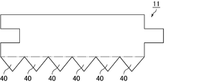
- the holding sealing material 11 shown in FIG. 5 has the same shape as the holding sealing material 10 shown in FIG. 1 except that each shape of the first cone heat insulating portion 40 is a triangle.
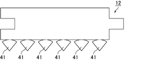
- the holding sealing material 12 shown in FIG. 6 has the same shape as the holding sealing material 10 shown in FIG. 1 except that each shape of the first cone heat insulating portion 41 is a fan shape.
- the shape of the first cone heat insulating portion is a triangle or a sector
- the sides of the adjacent first cone heat insulating portions are not in contact with each other. It is desirable to define the shape. If the triangular or fan-shaped shape is determined so that the sides of the adjacent first cone heat insulation parts are in contact with each other, the tip of the cone cylindrical part has a sharp shape, and the inflow of exhaust gas when the holding sealing material is arranged in the exhaust gas purification device This is because the path is blocked by the cone heat insulating portion.
- the holding sealing material 11 and the holding sealing material 12 when the holding sealing material is rolled into a cylindrical shape, if the sides of the adjacent first cone heat insulating portions are not in contact with each other, the gap between the first cone heat insulating portions is A gap is created. Therefore, when it is set as the exhaust gas purification apparatus using these holding sealing materials, a part of the inner peripheral surface is covered with the first cone heat insulating portion instead of the entire inner peripheral surface of the first cone member. Become.
- the holding sealing material 13 shown in FIG. 7A is an example of a holding sealing material in which the number of first cone heat insulating portions is one. Others are the same shape as the holding sealing material 10 shown in FIG.
- the first cone heat insulating portion 42 of the holding sealing material 13 has a shape obtained by removing a sector shape having the same center point and central angle as the sector shape and a small radius from the sector shape.
- the first cone heat insulating part 42 is connected to the first holding part side face 25 of the holding part 20 only at a part thereof. Even when the holding sealing material 13 is rolled into a cylindrical shape, as the diameter of the cone cylindrical portion formed as a space surrounded by the first cone heat insulating portion 42 is separated from the first holding portion side surface 25. The shape becomes gradually smaller.
- FIG. 7B shows a modification of the holding sealing material shown in FIG.
- the holding sealing material 13 ′ shown in FIG. 7B is a first cone heat insulating part 42 of the holding sealing material 13 shown in FIG. 7A, and the first cone heat insulating part 42 is the first of the holding part 20.
- the shape is such that the first cone heat insulating portions 42 a and 42 b are divided into two at the point where they are connected to the holding portion side surface 25, and are arranged at both ends of the first holding portion side surface 25.
- the shape of the cone heat insulating part is a shape obtained by excluding a fan shape having the same central point and central angle as the fan shape and a small radius from the fan shape as a whole. It is included in “a shape excluding a sector having the same central point and central angle and a small radius from the sector”.
- the number of cone heat insulation parts in this case is counted as one.
- the exhaust gas purification apparatus of the present invention may be an exhaust gas purification apparatus having a so-called eccentric cone in which the central axis of the first cone member is shifted from the central axis of the casing.
- An exhaust gas purifying apparatus having an eccentric cone and a holding sealing material suitable for such an exhaust gas purifying apparatus will be described below.
- FIG. 8 is a cross-sectional view schematically showing an example of an exhaust gas purifying apparatus having an eccentric cone.
- the central axis of the casing is in the longitudinal direction of the casing (the direction indicated by the double-headed arrow b in FIG. 8 and the direction parallel to the exhaust gas flow direction) at the first end and the second end of the casing. It is the axis
- the central axis of the casing 130 is indicated by a one-dot chain line 133.
- the central axis of the first cone member is at both ends of the first cone member, that is, at the end on the first end side of the casing and at the end farthest from the first end of the casing. It is an axis connecting the centroids of the cross-sectional shapes of the first cone members cut along the cross-section perpendicular to the longitudinal direction.
- the center axis of the first cone member 240 that is an eccentric cone is indicated by a one-dot chain line 242.
- the second cone member 250 is also an eccentric cone, and its central axis 252 is deviated from the direction of the alternate long and short dash line 133 that is the central axis of the casing.
- the central axis of the second cone member is at both ends of the second cone member, that is, at the end on the second end side of the casing and at the end farthest from the second end of the casing. It is an axis connecting the centroids of the cross-sectional shapes of the second cone members cut along the cross-section perpendicular to the longitudinal direction.
- the other structure of the exhaust gas purification apparatus 200 is the same as that of the exhaust gas purification apparatus 100 shown in FIG.
- FIG. 9, FIG. 10 (a) and FIG. 10 (b) are top views schematically showing another example of the holding sealing material of the present invention.
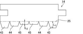
- the holding sealing material 14 shown in FIG. 9 is a holding sealing material that can be used in the exhaust gas purification apparatus of the present invention having an eccentric cone.
- the holding sealing material 14 is provided with a total of six trapezoidal first cone heat insulation parts, including two first cone heat insulation parts 43 having a high trapezoidal height and a trapezoidal height.
- the first holding portion in the first cone insulating section height from the 43 first holding portion side 25 L 1 is longer first cone insulation portion 45 short height L 3 from the side 25, a cone cylindrical portion. Therefore, as shown in the cross-sectional view of the exhaust gas purification apparatus 200 shown in FIG. 8, the first cone heat insulating portion 43 is located above the first cone member 240 (the side where the distance from the end surface of the casing of the first cone member is long). And the first cone heat insulating portion 45 is disposed on the lower side of the first cone member 240 (on the side where the distance from the end surface of the casing of the first cone member is short), whereby the first cone which is an eccentric cone is arranged. The inner peripheral surface of the cone member 240 can be covered with the first cone heat insulating portion.
- the holding sealing material 15 shown in FIG. 10A is an example of a holding sealing material that has one eccentric cone and can be used in the exhaust gas purification apparatus of the present invention having an eccentric cone.
- the first cone heat insulating part 46 of the holding sealing material 15 is a crescent moon type.
- the first cone heat insulating part 46 is connected to the first holding part side face 25 of the holding part 20 only at a part thereof. Even when such a holding sealing material 15 is rolled into a cylindrical shape, a portion having a long distance and a short portion from the side surface 25 of the first holding portion are generated in the first cone heat insulating portion 46. Covering the inner peripheral surface of the first cone member, which is an eccentric cone, with the first cone heat insulating portion by arranging the long and short portions of the first cone heat insulating portion according to the shape of the member. Can do.
- FIG. 10B shows a modification of the holding sealing material shown in FIG.
- the holding sealing material 15 ′ shown in FIG. 10B is the first cone heat insulating part 46 of the holding sealing material 15 shown in FIG. 10A, and the first cone heat insulating part 46 is the first of the holding part 20.
- the shape is such that the cone heat insulating portions 46 a and 46 b are divided into two at the point where they are connected to the holding portion side surface 25, and the divided cone heat insulating portions 46 a and 46 b are arranged at both ends of the first holding portion side surface 25.
- the shape of the cone heat insulating portion is a crescent shape as a whole, and the shape of the cone heat insulating portion is a crescent shape.
- the number of cone heat insulation parts in this case is counted as one.
- FIG. 11 is a cross-sectional view schematically showing an example of an exhaust gas purifying apparatus having a first inner cone member.
- the exhaust gas purifying apparatus 300 shown in FIG. 11 is provided with a first inner cone member 310.
- the first inner cone member 310 is welded and fixed to the first cone member 140 by a welding portion 311.
- the first cone heat insulating portion 30 is disposed between the first inner cone member 310 and the first cone member 140.
- the fiber scatter suppression processing unit (the fiber scatter suppression processing unit 37 and the fiber scatter suppression processing unit 38 in FIG. 3) is not provided in the first cone heat insulating unit 30.
- the other configuration of the exhaust gas purification apparatus 300 is the same as that of the exhaust gas purification apparatus 100 shown in FIG.
- the exhaust gas purification apparatus having the first inner cone member can be assembled by inserting the first cone heat insulating portion between the first inner cone member and the first cone member.
- the exhaust gas purification device may be assembled by a press-fitting process as shown in FIG. 4A, but the first cone heat insulating portion is inserted between the first inner cone member and the first cone member. Is difficult. Therefore, the wound body is press-fitted only into the cylindrical casing so that the first cone heat insulating portion protrudes from the casing, and the first inner cone member and the member to which the first cone member is welded are separately provided.
- a method for preparing and joining the first cone member and the first end of the casing by welding or the like while inserting the first cone heat insulating portion between the first inner cone member and the first cone member It is desirable to use
- the formation of the second cone member may be performed by welding a member processed into the shape of the second cone member, and the second end side of the casing is subjected to spinning processing (drawing processing) after press-fitting of the wound body. May be performed by processing into a cone shape.
- the holding sealing material of the present invention that can be used in the exhaust gas purification apparatus of the present invention further includes a second cone heat insulating portion that covers at least a part of the inner peripheral surface of the second cone member, and the holding portion and the first It is desirable that at least a part of the side surfaces of the two cone heat insulating portions are continuously connected.
- An exhaust gas purification apparatus including such a holding sealing material and the holding sealing material will be described below.
- FIG. 12 is a top view schematically showing an example of the holding sealing material of the present invention including the second cone heat insulating portion.
- the second cone heat insulating portion 50 is continuously connected to the second holding portion side surface 26.
- a plurality (six) of the second cone heat insulating portions 50 are provided, and each shape of the second cone heat insulating portions is a trapezoid.
- the form of the 2nd cone heat insulation part 50 can be made to be the same as that of the 1st cone heat insulation part 30 shown in FIG. 1 except that the position differs.
- the second cone heat insulating portion and the holding portion are continuously connected, they are usually the same material and are mat-like members having the same thickness.
- the slits and the fiber scattering suppression process are not shown in FIG. 12, but can be provided at the same positions as those provided in the first cone heat insulating portion 30 shown in FIG.
- a cone cylindrical portion that is a space surrounded by the second cone heat insulating portion 50 is formed as in the shape shown in FIG.
- the diameter of the cone cylindrical part surrounded by the second cone heat insulating part 50 is the largest at the second holding part side face 26 and is the same as the inner diameter of the cylinder formed by the holding part 20, but the second holding part As the distance from the side surface 26 increases, the distance gradually decreases.
- the number of the second cone heat insulating portions may be one or two, and the shape is not limited to the trapezoid.
- the shape of the first cone heat insulating portion may be a triangle, a fan shape, a fan shape having a central point and a central angle that are the same as that of the fan shape, and having a small radius, or a crescent moon shape. Moreover, it is good also as a 2nd cone heat insulation part of the shape corresponding to an eccentric cone.
- FIG. 13A is a cross-sectional view schematically showing an example of the exhaust gas purifying apparatus of the present invention in which the inner peripheral surface of the second cone member is covered with the second cone heat insulating portion.
- the holding sealing material 16 shown in FIG. 12 is used, and the second cone heat insulating part 50 continuously connected to the holding part 20 is a second cone. At least a part of the inner peripheral surface 151 of the member 150 is covered.
- the 2nd cone heat insulation part 50 it can provide in the position similar to the position provided in the 1st cone heat insulation part 30 shown in FIG.
- the assembly of the exhaust gas purification device 400 shown in FIG. 13A can be performed in the same manner as the assembly of the exhaust gas purification device shown in FIG.
- a member in which the second cone member 150 is joined to the second end portion of the cylindrical casing 130 by welding or the like is prepared, and the wound body is surrounded by the second cone heat insulating portion. You may make it press-fit from the 1st edge part 131 side of a casing by making a cylindrical part into the head. After the press fitting, the first cone member 140 can be joined to the first end 131 of the casing by welding or the like to form the exhaust gas purification device 400.
- FIG.13 (b) is sectional drawing which shows typically an example of the exhaust gas purification apparatus provided with the 1st inner cone member and the 2nd inner cone member.
- a second inner cone member 510 is provided in the exhaust gas purifying apparatus 500 shown in FIG.
- the second inner cone member 510 is welded and fixed to the second cone member 150 by a welding portion 511.
- the second cone heat insulating portion 50 is disposed between the second inner cone member 510 and the second cone member 150. If the 2nd cone heat insulation part 50 is arrange
- the second corn heat insulating portion 50 is not provided with a fiber scattering suppression processing portion.
- the other structure of the exhaust gas purification apparatus 500 is the same as that of the exhaust gas purification apparatus 400 shown in FIG.
- the wound body is press-fitted only into the cylindrical casing as in the assembly of the exhaust gas purification apparatus having the first inner cone member.
- the first cone heat insulation portion and the second cone heat insulation portion protrude from the casing, the first inner cone member and the first cone member welded, the second inner cone member and the second A member to which the second cone member is welded is prepared separately, the first cone heat insulating portion is inserted, the first cone member and the first end of the casing are welded, and the second cone heat insulating portion is inserted.
- a method of sequentially welding the second cone member and the second end of the casing can be used.
- the holding sealing material of the present invention that can be used in the exhaust gas purifying apparatus of the present invention preferably further includes a strip portion that is continuously connected to the side surface of the second cone heat insulating portion.
- An exhaust gas purification apparatus including such a holding sealing material and the holding sealing material will be described below.
- FIG. 14 is a top view schematically showing an example of the holding sealing material of the present invention having a strip portion.
- the strip portion 60 having a substantially rectangular shape in plan view is formed on the side surface 51 located on the opposite side to the side surface connected to the holding portion 20 among the side surfaces of the second cone heat insulating portion 50. Is provided.
- the strip portion 60 is connected to a part of the side surface of the second cone heat insulating portion 50.
- the strip portion, the second cone heat insulating portion and the holding portion are continuously connected to each other, these are usually the same material and are mat-like members having the same thickness. is there.
- the slit is not shown in FIG.
- FIG. 15 is a cross-sectional view schematically showing an example of the exhaust gas purifying apparatus of the present invention in which the inner peripheral surface of the straight pipe member is covered with a strip portion.
- a straight pipe member 160 that is a cylindrical member having a constant diameter is disposed at the end 152 of the second cone member 150 opposite to the casing 130 side. Yes.
- the strip portion 60 continuously connected to the second cone heat insulating portion 50 is at least on the inner peripheral surface 161 of the straight pipe member 160. It covers a part.
- a slit 65 at a portion where the second cone heat insulating portion 50 and the strip portion 60 are connected is provided inside the exhaust gas purification device. It is desirable that a fiber scattering suppression process is provided on the surface of the strip portion 60 and exposed to the exhaust gas purification device.
- the exhaust gas purification device 600 shown in FIG. 15 is assembled in such a manner that the strip portion protrudes from the second cone member by the method of assembling the exhaust gas purification device 400 shown in FIG. It can carry out by the method of welding to 2 cone members. A member obtained by previously joining the straight pipe member and the second cone member by welding or the like may be used.
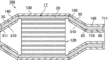
- FIG. 16 is a cross-sectional view schematically showing an example of the exhaust gas purifying apparatus of the present invention having a second inner cone member and an inner straight pipe member.
- the exhaust gas purifying device 700 is provided with a second inner cone member 510.
- an inner straight pipe member 710 that is smaller than the diameter of the straight pipe member 160 and is symmetrical to the straight pipe member 160 is also provided.
- the second inner cone member 510 and the inner straight tube member 710 are joined to the end portion of the straight tube member 160 by a welded portion 711 provided at the end portion of the inner straight tube member 710.
- the 2nd cone heat insulation part 50 and the strip part 60 are each arrange
- the positions of the second cone heat insulating portion and the strip portion are stabilized in the exhaust gas purification apparatus, and the scattering of fibers from the surfaces of the second cone heat insulating portion and the strip portion can be suppressed. it can.
- the wound body is press-fitted only into the cylindrical casing. Then, the first cone heat insulation part, the second cone heat insulation part, and the strip part protrude from the casing.
- a member in which the first inner cone member and the first cone member are welded is prepared. Further, a member is prepared in which the second cone member and the straight pipe member are welded, the second inner cone member and the inner straight pipe member are welded, and the inner straight pipe member and the straight pipe member are welded.
- the first cone heat insulating portion is inserted and the first cone member and the first end of the casing are welded.
- the strip portion and the second cone heat insulating portion are inserted into the gap between the second cone member and the second inner cone member with the strip portion at the top. Insertion of the strip portion and the second cone heat insulating portion proceeds, the strip portion is disposed between the straight pipe member and the inner straight pipe member, and the second portion is disposed between the second cone member and the second inner cone member.
- the second cone member and the second end portion of the casing are welded.
- the holding sealing material of the present invention that can be used in the exhaust gas purifying apparatus of the present invention may be one in which another strip heat insulating portion and another holding portion are connected to the strip portion.
- Such a holding sealing material is suitably used for an exhaust gas purifying apparatus including two exhaust gas treatment bodies.
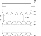
- FIG. 17 is a top view schematically showing an example of the holding sealing material of the present invention in which another cone heat insulating portion and another holding portion are connected to the strip portion.
- the holding sealing material 18 shown in FIG. 17 includes a second holding portion 80 that is a portion that holds the second exhaust gas treating body, and a third cone that is continuously connected to the side surface of the second holding portion 80.
- the heat insulation part 70 is provided, and the third cone heat insulation part 70 is continuously connected to the side face 61 opposite to the side face connected to the second cone heat insulation part 50 on the side face of the strip part 60. That is, the holding sealing material 18 includes the first cone heat insulating portion 30, the holding portion 20, the second cone heat insulating portion 50, the strip portion 60, the third cone heat insulating portion 70, and the second holding portion 80. It is connected. Since the configuration of each part is the same as the configuration of the other holding sealing materials described so far, detailed description thereof is omitted, but the second holding unit 80, the holding unit 20, and the third cone heat insulating unit 70 are omitted. And the 1st cone heat insulation part 30 can be set as the same structure, respectively.
- the relationship between the second holding unit 80 and the third cone heat insulating unit 70 can be the same as the relationship between the holding unit 20 and the first cone heat insulating unit 30. Furthermore, the relationship between the third cone heat insulating portion 70 and the strip portion 60 can be made the same as the relationship between the second cone heat insulating portion 50 and the strip portion 60.
- FIG. 18 is a cross-sectional view schematically showing an example of the exhaust gas purifying apparatus of the present invention having two exhaust gas treating bodies.
- another exhaust gas treatment body 220 is provided on the downstream side of the exhaust gas.
- the exhaust gas treatment body 220 is a DPF, and has a columnar shape in which a large number of cells 225 are arranged in parallel in the longitudinal direction with a cell wall 226 interposed therebetween.
- One end of the cell 225 is sealed with a sealing material 228.
- the exhaust gas flows into one cell 225 that opens to the exhaust gas inflow side end surface 220 a of the exhaust gas treatment body 220, and passes through the cell wall 226 that separates the cell 225.
- PM in the exhaust gas is collected by the cell wall 226, and the exhaust gas is purified.
- the purified exhaust gas flows out from another cell 225 opened in the exhaust gas outflow side end face 220b and is discharged to the outside.
- a second holding portion 80 that is a part of the holding sealing material 18 is wound, and the second holding portion 80 is interposed between the exhaust gas treatment body 220 and the second casing 180. It is arranged.
- a third cone member 170 is disposed at the first end 181 located on the exhaust gas inflow side of the second casing 180, and the third cone member 170 is opposite to the second casing 180 side.
- a straight pipe member 160 is disposed at the end of the tube.
- a fourth cone member 190 is disposed on the second end 182 located on the exhaust gas outflow side of the second casing 180.
- the third cone heat insulating portion 70 continuously connected to the second holding portion 80 covers at least a part of the inner peripheral surface 171 of the third cone member 170.
- the relationship between the third cone heat insulating portion 70 and the third cone member 170 can be the same as the relationship between the first cone heat insulating portion 30 and the first cone member 140.
- the structure from the 1st cone member 140 to the straight pipe member 160 shown on the left side in FIG. 18 can be made the same as the form demonstrated so far, the detailed description is abbreviate
- a clamshell type means a member in which a cylindrical member is divided, such as a semi-cylinder.
- a semi-cylindrical casing is covered from above and below a wound body in which a holding seal material holding part is wrapped around an exhaust gas treatment body, and the upper and lower casings are welded.
- the wound body is accommodated in the casing by being fixed by.
- the manufacturing method of the holding sealing material of this invention is characterized by performing a step of punching out the holding sealing material from one sheet so that all the parts constituting the holding sealing material are connected.
- a mat containing inorganic fibers is produced.
- the mat can be obtained by various methods.
- the mat can be produced by a needling method or a papermaking method.
- the needling method for example, it can be produced by the following method. That is, first, an inorganic fiber precursor having an average fiber diameter of 3 to 10 ⁇ m is produced by spinning a spinning mixture using, for example, a basic aluminum chloride aqueous solution and silica sol as raw materials. Subsequently, the inorganic fiber precursor is compressed to produce a continuous sheet-like material having a predetermined size, subjected to a needle punching process, and then subjected to a firing process to complete the preparation of the mat.
- the papermaking method by mixing inorganic fibers such as alumina fibers and silica fibers, an inorganic binder, and water so that the content of the inorganic fibers in the raw material liquid becomes a predetermined value, and stirring with a stirrer Prepare a mixture.
- the mixed solution may contain a colloidal solution made of a polymer compound or a resin as necessary.
- seat is produced by dehydrating the water in a liquid mixture through a mesh. Thereafter, the preparation of the mat is completed by heating and compressing the raw material sheet under predetermined conditions.
- the mat may be subjected to a drying treatment by applying a binder solution containing an organic binder and / or an inorganic binder as necessary.
- the holding sealing material of the present invention can be obtained by punching the mat into the shape of the holding sealing material.
- the holding sealing material can be punched with a Thomson blade, a guillotine blade, or the like.
- the first cone member is covered with the first cone heat insulating portion, the heat radiation from the first cone member can be suppressed. Moreover, since the holding part and the first cone heat insulating part are continuously connected, there is no positional displacement, and the holding part and the first cone heat insulating part are made of one member, so that the exhaust gas purification apparatus is assembled. Excellent in properties.
- the exhaust gas purifying apparatus of the present invention is used in various forms such as having an eccentric cone, having a second cone member, having a straight pipe member, and having a second exhaust gas treating body.
- the heat insulating portion can be provided at a necessary place in each embodiment, heat radiation from the exhaust gas purification device can be suppressed.
- the holding sealing material of the present invention can cover both the exhaust gas treating body and the cone member by using one holding sealing material without causing positional displacement. Further, since it can be flat when stored and transported, it becomes a holding sealing material with high storage and transport efficiency.
- a mat containing inorganic fibers was prepared by the following procedure.
- a needle processing mat having a bulk density of 0.15 g / cm 3 and a basis weight of 1500 g / m 2 was produced by performing a needling process on the base mat.
- an acrylic latex emulsion was prepared by sufficiently dispersing acrylic latex in water, and this was used as a binder.
- the needle mat is cut into a total length of 1250 mm ⁇ width of 1200 mm in a plan view, and the binder needle is impregnated into the binder so that the amount of binder attached to 100% by weight of the cut needle mat is 1.0% by weight. did.
- the needle mat impregnated with the binder was air-dried at a temperature of 140 ° C. for 6 minutes to produce a mat as one sheet.
- the mat thickness was 9.0 mm.
- Examples 1 to 8 The mat was punched using a Thomson blade having a predetermined shape to produce holding sealing materials according to Examples 1 to 8 having the following shapes.
- the length (long side length) of the holding sealing material in the longitudinal direction was 593 mm, and the width (short side length) of the holding portion was 193 mm.
- Example 1 A shape having six trapezoidal first cone heat insulating portions (shape in FIG. 1). The trapezoid was an isosceles trapezoid with an upper base of 27 mm, a lower base of 97 mm, and a height of 160 mm.
- Example 2 A shape having six trapezoidal first cone heat insulation portions and six second cone heat insulation portions as in Example 1 (shape in FIG. 12).
- Example 3 A shape having six triangular first cone heat insulating portions (the shape shown in FIG. 5). The triangular shape was an isosceles triangle having a base of 97 mm and a height of 160 mm.
- Example 4 A shape having one first cone heat insulating portion having a shape in which a sector shape having the same center point and central angle as the sector shape and a small radius is removed from the sector shape (the shape shown in FIG. 7A).
- the large fan-shaped shape had a central angle of 156 ° and a radius of 214 mm, and the small fan-shaped radius was 50 mm.
- Example 5 A shape having six trapezoidal first cone heat insulating portions having different heights (the shape in FIG. 9). The height of the trapezoid was 180 mm, 160 mm, and 140 mm in descending order.
- each trapezoid is 97 mm
- the upper base of an isosceles trapezoid with a height of 160 mm is 27 mm
- the trapezoids with a height of 180 mm and 140 mm have an angle between each trapezoidal leg and the lower base of 160 mm
- Example 6 Shape having one crescent-shaped first cone heat insulating portion (shape of FIG. 10A). The crescent shape was such that the radius of the outer arc was 300 mm, the radius of the inner arc was 1140 mm, and the distance between the center of the outer arc and the center of the inner arc was 1000 mm.
- Example 7 Example of holding sealing material provided with slits
- Example 7 In Example 1, a slit having a depth of 4 mm is provided at a part where the holding part and the first cone heat insulating part are continuously connected.
- Example 8 Example of holding sealing material provided with strips
- Example 8 A shape further having a strip portion connected to the second cone heat insulating portion in Example 2 (shape of FIG. 14). The shape of the strip is 194 mm long and 80 mm wide. Each of the portions where the holding portion, the first cone heat insulating portion, and the second cone heat insulating portion are continuously connected, and the depth where the second cone heat insulating portion and the strip portion are continuously connected are deep.
- a 4 mm slit was provided.
- An exhaust gas purification apparatus was produced using the holding sealing material or the three-dimensional molded body.
- the configuration of the exhaust gas purification apparatus is configured to include a total of two exhaust gas treatment bodies, one on the upstream side and one on the downstream side, and the holding sealing materials of the examples and comparative examples hold the exhaust gas treatment body on the upstream side. Used as a sealing material.
- the 1st cone heat insulation part was arrange
- the first inner cone member as shown in FIG. 11 was provided for Examples 1, 3, 4, 7 and Comparative Example 1. An exhaust gas purification device was obtained.
- Example 2 it is set as the exhaust gas purification apparatus provided with the 1st inner cone member and the 2nd inner cone member as shown in FIG.13 (b), and a 2nd cone heat insulation part is a 2nd cone member. It arrange
- Example 5, 6 it is an exhaust gas purification apparatus which has an eccentric cone as shown in FIG. 8, Comprising: A 1st cone member is an eccentric cone corresponding to the shape of a holding
- Example 8 it is set as the exhaust gas purification apparatus provided with the 1st inner cone member, the 2nd inner cone member, and the straight pipe member as shown in FIG.
- Comparative Example 1 had to perform the assembling of the cone heat insulating portion as a separate member, and the workability was poor.
- the first cone heat insulating portion and the holding portion can be assembled as one member, and workability is good.
- Table 1 those having good workability are shown as “ ⁇ ”, and those having poor workability are shown as “X”.
- Heat retention An exhaust gas at a predetermined temperature (600 ° C.) was introduced into the exhaust gas purification device, and the temperature of the exhaust gas after flowing out of the exhaust gas purification device through the two exhaust gas treatment bodies was measured to evaluate heat retention.
- ⁇ those with extremely good heat retention
- ⁇ those with good heat are shown as ⁇ .
- the three-dimensional molded body of Comparative Example 2 was bulky during storage and packaging.
- the holding sealing material was matt and was not bulky.
- Table 1 those that are not particularly bulky are indicated by ⁇ , those that are not bulky are indicated by ⁇ , and those that are bulky are indicated by ⁇ .
- Fiber scattering suppression treatment provided on the holding unit surface 1st cone heat insulation part 30,40,41,42,42a, 42b, 43,44,45,46,46a, 46b Slit 35 Cone cylinder 36
- Fiber scattering suppression treatment 37 provided on the surface of the first cone heat insulating part
- Fiber scattering suppression treatment 38 provided on the side surface of the first cone heat insulating portion 38 Second cone insulation 50 Strip 60
Landscapes
- Engineering & Computer Science (AREA)
- Chemical & Material Sciences (AREA)
- Chemical Kinetics & Catalysis (AREA)
- Combustion & Propulsion (AREA)
- Mechanical Engineering (AREA)
- General Engineering & Computer Science (AREA)
- Health & Medical Sciences (AREA)
- Toxicology (AREA)
- Exhaust Gas After Treatment (AREA)
Abstract
排ガス浄化装置における断熱材の位置ずれが生じず、排ガス浄化装置の組み付けの作業性に優れた排ガス浄化装置を提供すること。 排ガス処理体と、排ガス流入側に位置する第1の端部及び排ガス流出側に位置する第2の端部を有し、上記排ガス処理体を収容する筒状のケーシングと、上記ケーシングの第1の端部側に配設された筒状部材であり、その径が上記ケーシングの第1の端部から離れるに従って次第に小さくなっている第1のコーン部材と、上記ケーシングの第2の端部側に配設された筒状部材であり、その径が上記ケーシングの第2の端部から離れるに従って次第に小さくなっている第2のコーン部材と、無機繊維を含むマットからなり、その一部が上記排ガス処理体の周囲に巻きつけられて、上記排ガス処理体及び上記ケーシングの間に配設されている保持シール材とを備えた排ガス浄化装置であって、上記保持シール材は、上記排ガス処理体の周囲に巻きつけられた保持部と、上記第1のコーン部材の内周面の少なくとも一部を覆う第1のコーン断熱部とを備えており、上記保持部と上記第1のコーン断熱部は互いの側面の少なくとも一部が連続して繋がっていることを特徴とする排ガス浄化装置。
Description
本発明は、排ガス浄化装置、保持シール材及び保持シール材の製造方法に関する。
従来、エンジン等の内燃機関から排出された排ガス中に含まれる有害ガス等の有害物質を浄化するため、内燃機関の排気通路(排ガスが流通する排気管等)には、排ガス浄化装置が設けられている。
排ガス浄化装置は、内燃機関の排気通路にケーシングを設け、ケーシングの中に排ガス処理体を配置した構造となっている。排ガス処理体の一例としては、触媒担体又はディーゼルパティキュレートフィルタ(DPF)が挙げられる。
排ガス浄化装置は、内燃機関の排気通路にケーシングを設け、ケーシングの中に排ガス処理体を配置した構造となっている。排ガス処理体の一例としては、触媒担体又はディーゼルパティキュレートフィルタ(DPF)が挙げられる。
排ガス処理体には無機繊維集合体からなる保持シール材が巻きつけられて、ケーシング内に配設される。この保持シール材は、自動車の走行等により生じる振動や衝撃により、排ガス処理体がその外周を覆うケーシングと接触して破損するのを防止することや、排ガス処理体とケーシングとの間から排気ガスが漏れることを防止すること等を主な目的として配設されている。
排ガス処理体に触媒が担持された排ガス浄化装置による有害物質の浄化効率を高めるためには、内燃機関の排気通路及び排ガスの温度を触媒活性化に適した温度(以下、触媒活性化温度ともいう)に維持する必要がある。
排ガス処理体に触媒が担持された排ガス浄化装置は、所定の触媒活性化温度に達するまで昇温した状態でないと、充分な触媒作用を奏することができない。
そのため、排ガス浄化装置には、排ガス処理体の温度が低下しないようにする保温性能が求められる。
そのため、排ガス浄化装置には、排ガス処理体の温度が低下しないようにする保温性能が求められる。
排ガス処理体に巻きつけられる保持シール材には、排ガス処理体を保持する機能の他に、排ガス処理体を保温する作用も期待されている。また、排ガス浄化装置の排ガス流入側に位置するコーン部からの放熱が問題になる場合があり、コーン部を2重管として、2重管内に断熱材を挿入することにより、コーン部からの放熱を抑制する技術が知られている。
また、保持シール材による排ガス処理体の保持を、ケーシングの形状に合わせた3次元成形体により行う技術も知られている(例えば、特許文献1参照)。
排ガス浄化装置の保温のために、排ガス処理体に保持シール材を巻きつけ、さらにコーン部の2重管に断熱材を挿入する方法であると、保持シール材と断熱材が別々の部材であるため、排ガス浄化装置の組み付けの際の工数が多く、作業性が悪い。また、断熱材の位置がずれやすく、断熱材の位置がずれると保持シール材と断熱材の間に隙間が生じて断熱性能が不充分になるという問題があった。
また、3次元成形体を用いる方法であると、3次元形状が嵩張るため保持シール材の製造後の保管時、搬送時に嵩張って、保管、搬送効率が低く、好ましくない。
また、3次元成形体を用いる方法であると、3次元形状が嵩張るため保持シール材の製造後の保管時、搬送時に嵩張って、保管、搬送効率が低く、好ましくない。
本発明は、排ガス浄化装置における断熱材の位置ずれが生じず、排ガス浄化装置の組み付けの作業性に優れた排ガス浄化装置を提供することを目的とする。
また、本発明は排ガス処理体とコーン部の断熱性能に優れ、排ガス処理体とコーン部材の両方を、位置ずれを生じることなく覆うことができ、かつ、保管、搬送効率の高い保持シール材を提供すること、及び、上記保持シール材の製造方法を提供することを目的とする。
また、本発明は排ガス処理体とコーン部の断熱性能に優れ、排ガス処理体とコーン部材の両方を、位置ずれを生じることなく覆うことができ、かつ、保管、搬送効率の高い保持シール材を提供すること、及び、上記保持シール材の製造方法を提供することを目的とする。
上記目的を達成するための、本発明の排ガス浄化装置は、排ガス処理体と、
排ガス流入側に位置する第1の端部及び排ガス流出側に位置する第2の端部を有し、上記排ガス処理体を収容する筒状のケーシングと、
上記ケーシングの第1の端部側に配設された筒状部材であり、その径が上記ケーシングの第1の端部から離れるに従って次第に小さくなっている第1のコーン部材と、
上記ケーシングの第2の端部側に配設された筒状部材であり、その径が上記ケーシングの第2の端部から離れるに従って次第に小さくなっている第2のコーン部材と、
無機繊維を含むマットからなり、その一部が上記排ガス処理体の周囲に巻きつけられて、上記排ガス処理体及び上記ケーシングの間に配設されている保持シール材とを備えた排ガス浄化装置であって、
上記保持シール材は、
上記排ガス処理体の周囲に巻きつけられた保持部と、
上記第1のコーン部材の内周面の少なくとも一部を覆う第1のコーン断熱部とを備えており、
上記保持部と上記第1のコーン断熱部は互いの側面の少なくとも一部が連続して繋がっていることを特徴とする。
排ガス流入側に位置する第1の端部及び排ガス流出側に位置する第2の端部を有し、上記排ガス処理体を収容する筒状のケーシングと、
上記ケーシングの第1の端部側に配設された筒状部材であり、その径が上記ケーシングの第1の端部から離れるに従って次第に小さくなっている第1のコーン部材と、
上記ケーシングの第2の端部側に配設された筒状部材であり、その径が上記ケーシングの第2の端部から離れるに従って次第に小さくなっている第2のコーン部材と、
無機繊維を含むマットからなり、その一部が上記排ガス処理体の周囲に巻きつけられて、上記排ガス処理体及び上記ケーシングの間に配設されている保持シール材とを備えた排ガス浄化装置であって、
上記保持シール材は、
上記排ガス処理体の周囲に巻きつけられた保持部と、
上記第1のコーン部材の内周面の少なくとも一部を覆う第1のコーン断熱部とを備えており、
上記保持部と上記第1のコーン断熱部は互いの側面の少なくとも一部が連続して繋がっていることを特徴とする。
本発明の排ガス浄化装置では、保持シール材が、保持部及び第1のコーン断熱部を備えており、保持部が排ガス処理体の周囲に巻きつけられて排ガス処理体を保温し、第1のコーン断熱部が第1のコーン部材の内周面を覆って第1のコーン部材を保温する。
第1のコーン部材は排ガス流入側に位置しているため排ガスの温度が高く、保温の必要性が高い部分であるが、本発明の排ガス浄化装置では第1のコーン部材が第1のコーン断熱部で覆われるため、第1のコーン部材からの放熱を抑制することができる。
また、保持部及び第1のコーン断熱部は連続して繋がっているため位置ずれを生じることはなく、保持部と第1のコーン断熱部が1つの部材からなるため排ガス浄化装置の組み付けの作業性に優れる。
第1のコーン部材は排ガス流入側に位置しているため排ガスの温度が高く、保温の必要性が高い部分であるが、本発明の排ガス浄化装置では第1のコーン部材が第1のコーン断熱部で覆われるため、第1のコーン部材からの放熱を抑制することができる。
また、保持部及び第1のコーン断熱部は連続して繋がっているため位置ずれを生じることはなく、保持部と第1のコーン断熱部が1つの部材からなるため排ガス浄化装置の組み付けの作業性に優れる。
本発明の排ガス浄化装置では、上記第1のコーン断熱部の数は1つであることが望ましい。
また、上記第1のコーン断熱部の形状は、扇形からその扇形と中心点及び中心角が同じで半径の小さい扇形を除いた形状、又は、三日月形であることが望ましい。
第1のコーン断熱部が上記形状であると、1つのコーン断熱部で、第1のコーン部材の内周面と略同じ形状を形作ることができ、第1のコーン部材の内周面を覆うことができる。
また、上記第1のコーン断熱部の形状は、扇形からその扇形と中心点及び中心角が同じで半径の小さい扇形を除いた形状、又は、三日月形であることが望ましい。
第1のコーン断熱部が上記形状であると、1つのコーン断熱部で、第1のコーン部材の内周面と略同じ形状を形作ることができ、第1のコーン部材の内周面を覆うことができる。
本発明の排ガス浄化装置では、上記第1のコーン断熱部の数は2つ以上であることが望ましい。また、上記第1のコーン断熱部のそれぞれの形状は、三角形、台形又は扇形であることが望ましい。
第1のコーン断熱部が上記形状であると、2つ以上のコーン断熱部を組み合わせて、第1のコーン部材の内周面と略同じ形状を形作ることができ、第1のコーン部材の内周面を覆うことができる。
第1のコーン断熱部が上記形状であると、2つ以上のコーン断熱部を組み合わせて、第1のコーン部材の内周面と略同じ形状を形作ることができ、第1のコーン部材の内周面を覆うことができる。
本発明の排ガス浄化装置では、上記第1のコーン断熱部により、上記第1のコーン部材の内周面の全部が覆われていることが望ましい。
第1のコーン部材の内周面の全部が覆われていると、断熱性能がさらに優れた排ガス浄化装置とすることができる。
第1のコーン部材の内周面の全部が覆われていると、断熱性能がさらに優れた排ガス浄化装置とすることができる。
本発明の排ガス浄化装置では、上記第1のコーン部材の中心軸が、上記ケーシングの中心軸とずれていることが望ましい。
第1のコーン部材の中心軸がケーシングの中心軸とずれている、偏心コーンを有する排ガス浄化装置とすると、車載時に排ガス浄化装置周囲のスペースを有効に活用でき、デザインの自由度が増すため好ましい。
第1のコーン部材の中心軸がケーシングの中心軸とずれている、偏心コーンを有する排ガス浄化装置とすると、車載時に排ガス浄化装置周囲のスペースを有効に活用でき、デザインの自由度が増すため好ましい。
本発明の排ガス浄化装置では、上記保持部と上記第1のコーン断熱部が連続して繋がっている部位には、保持シール材の厚さ方向にスリットが設けられていることが望ましい。
上記スリットが設けられていると、保持部と第1のコーン断熱部が連続して繋がっている部位を容易に折り曲げることができるため、第1のコーン断熱部を第1のコーン部材の内周面に沿って配置させることが容易になる。
上記スリットが設けられていると、保持部と第1のコーン断熱部が連続して繋がっている部位を容易に折り曲げることができるため、第1のコーン断熱部を第1のコーン部材の内周面に沿って配置させることが容易になる。
本発明の排ガス浄化装置では、上記保持部の表面が上記ケーシング内の空間に露出している部位には、繊維飛散抑制処理がされていることが望ましい。
保持部の幅が排ガス処理体の長手方向の長さより大きい場合、保持部の表面の一部がケーシング内の空間に露出する。この部位に、無機バインダの塗布等の繊維飛散抑制処理がされていると排ガス浄化装置の組み付け作業時及び排ガス浄化装置の使用時に繊維飛散が抑制されるため好ましい。
保持部の幅が排ガス処理体の長手方向の長さより大きい場合、保持部の表面の一部がケーシング内の空間に露出する。この部位に、無機バインダの塗布等の繊維飛散抑制処理がされていると排ガス浄化装置の組み付け作業時及び排ガス浄化装置の使用時に繊維飛散が抑制されるため好ましい。
本発明の排ガス浄化装置では、上記第1のコーン断熱部の表面及び/又は側面には、繊維飛散抑制処理がされていることが望ましい。
第1のコーン断熱部の上記部位に、無機バインダの塗布等の繊維飛散抑制処理がされていると排ガス浄化装置の組み付け作業時及び排ガス浄化装置の使用時に繊維飛散が抑制されるため好ましい。
第1のコーン断熱部の上記部位に、無機バインダの塗布等の繊維飛散抑制処理がされていると排ガス浄化装置の組み付け作業時及び排ガス浄化装置の使用時に繊維飛散が抑制されるため好ましい。
本発明の排ガス浄化装置では、上記第1のコーン部材の内側に、その径が上記第1のコーン部材の径より小さく、上記第1のコーン部材と対称の形状である第1の内コーン部材が設けられており、
上記第1のコーン断熱部は、上記第1のコーン部材及び上記第1の内コーン部材の間に配設されていることが望ましい。
上記構成であると、第1のコーン断熱部が第1のコーン部材及び第1の内コーン部材の間に挟まれた状態となるので、第1のコーン断熱部の位置が排ガス浄化装置内で安定する。
また、第1のコーン断熱部の表面が第1の内コーン部材で覆われるため第1のコーン断熱部からの繊維飛散が抑制される点でも好ましい。
上記第1のコーン断熱部は、上記第1のコーン部材及び上記第1の内コーン部材の間に配設されていることが望ましい。
上記構成であると、第1のコーン断熱部が第1のコーン部材及び第1の内コーン部材の間に挟まれた状態となるので、第1のコーン断熱部の位置が排ガス浄化装置内で安定する。
また、第1のコーン断熱部の表面が第1の内コーン部材で覆われるため第1のコーン断熱部からの繊維飛散が抑制される点でも好ましい。
本発明の排ガス浄化装置において、上記保持シール材は、
上記第2のコーン部材の内周面の少なくとも一部を覆う第2のコーン断熱部をさらに備えており、
上記保持部と上記第2のコーン断熱部は互いの側面の少なくとも一部が連続して繋がっていることが望ましい。
上記構成であると、排ガス浄化装置の排ガス流出側に位置する第2のコーン部材からの放熱を第2のコーン断熱部により抑制することができる。
また、第2のコーン断熱部も保持部と連続して繋がっているため位置ずれを生じることはなく、保持部、第1のコーン断熱部及び第2のコーン断熱部が1つの部材からなるため排ガス浄化装置の組み付けの作業性に優れる。
上記第2のコーン部材の内周面の少なくとも一部を覆う第2のコーン断熱部をさらに備えており、
上記保持部と上記第2のコーン断熱部は互いの側面の少なくとも一部が連続して繋がっていることが望ましい。
上記構成であると、排ガス浄化装置の排ガス流出側に位置する第2のコーン部材からの放熱を第2のコーン断熱部により抑制することができる。
また、第2のコーン断熱部も保持部と連続して繋がっているため位置ずれを生じることはなく、保持部、第1のコーン断熱部及び第2のコーン断熱部が1つの部材からなるため排ガス浄化装置の組み付けの作業性に優れる。
本発明の排ガス浄化装置では、上記第2のコーン断熱部の数は1つであることが望ましい。
また、上記第2のコーン断熱部の形状は、扇形からその扇形と中心点及び中心角が同じで半径の小さい扇形を除いた形状、又は、三日月形であることが望ましい。
また、上記第2のコーン断熱部の形状は、扇形からその扇形と中心点及び中心角が同じで半径の小さい扇形を除いた形状、又は、三日月形であることが望ましい。
本発明の排ガス浄化装置では、上記第2のコーン断熱部の数は2つ以上であることが望ましい。また、上記第2のコーン断熱部のそれぞれの形状は、三角形、台形又は扇形であることが望ましい。
本発明の排ガス浄化装置では、上記第2のコーン部材の、上記ケーシング側と反対の端部には、その径が一定の筒状部材である直管部材が配設されており、
上記保持シール材は、
上記直管部材の内周面の少なくとも一部を覆う短冊部をさらに備えており、
上記第2のコーン断熱部と上記短冊部は互いの側面の少なくとも一部が連続して繋がっていることが望ましい。
上記構成であると、第2のコーン部材からさらに排ガス流出側に位置する直管部材からの放熱を短冊部により抑制することができる。
また、短冊部も第2のコーン断熱部と連続して繋がっているため位置ずれを生じることはなく、保持部、第1のコーン断熱部、第2のコーン断熱部及び短冊部が1つの部材からなるため排ガス浄化装置の組み付けの作業性に優れる。
上記保持シール材は、
上記直管部材の内周面の少なくとも一部を覆う短冊部をさらに備えており、
上記第2のコーン断熱部と上記短冊部は互いの側面の少なくとも一部が連続して繋がっていることが望ましい。
上記構成であると、第2のコーン部材からさらに排ガス流出側に位置する直管部材からの放熱を短冊部により抑制することができる。
また、短冊部も第2のコーン断熱部と連続して繋がっているため位置ずれを生じることはなく、保持部、第1のコーン断熱部、第2のコーン断熱部及び短冊部が1つの部材からなるため排ガス浄化装置の組み付けの作業性に優れる。
本発明の保持シール材は、無機繊維を含むマットからなり、
長手方向に伸びる長辺と上記長辺にほぼ直角な短辺とを有する平面視略矩形状の保持部と、
上記保持部の上記長辺側の側面の1つである第1の保持部側面及び上記第1の保持部側面と反対側の長辺側の側面である第2の保持部側面を有し、上記第1の保持部側面と少なくとも一部が連続して繋がっている第1のコーン断熱部とを備えた保持シール材であって、
上記保持部の2つの上記短辺同士が接するように保持シール材を筒状に丸めた際に、上記第1のコーン断熱部により囲まれた空間として形成されるコーン筒状部の径が上記第1の保持部側面から離れるに従って次第に小さくなることを特徴とする。
長手方向に伸びる長辺と上記長辺にほぼ直角な短辺とを有する平面視略矩形状の保持部と、
上記保持部の上記長辺側の側面の1つである第1の保持部側面及び上記第1の保持部側面と反対側の長辺側の側面である第2の保持部側面を有し、上記第1の保持部側面と少なくとも一部が連続して繋がっている第1のコーン断熱部とを備えた保持シール材であって、
上記保持部の2つの上記短辺同士が接するように保持シール材を筒状に丸めた際に、上記第1のコーン断熱部により囲まれた空間として形成されるコーン筒状部の径が上記第1の保持部側面から離れるに従って次第に小さくなることを特徴とする。
本発明の保持シール材を用いると、排ガス処理体とコーン部材の両方を、位置ずれを生じることなく1枚の保持シール材を用いて覆うことができる。
また、保管時及び搬送時には平面状とすることができるので、保管、搬送効率の高い保持シール材となる。
また、保管時及び搬送時には平面状とすることができるので、保管、搬送効率の高い保持シール材となる。
本発明の保持シール材において、上記第1のコーン断熱部の数は1つであることが望ましい。また、上記第1のコーン断熱部の形状は、扇形からその扇形と中心点及び中心角が同じで半径の小さい扇形を除いた形状、又は、三日月形であることが望ましい。
第1のコーン断熱部が上記形状であると、1つのコーン断熱部で、コーン部材の内周面と略同じ形状を形作ることができ、コーン部材の内周面を覆うことができる。
第1のコーン断熱部が上記形状であると、1つのコーン断熱部で、コーン部材の内周面と略同じ形状を形作ることができ、コーン部材の内周面を覆うことができる。
本発明の保持シール材において、上記第1のコーン断熱部の数は2つ以上であることが望ましい。また、上記第1のコーン断熱部のそれぞれの形状は、三角形、台形又は扇形であることが望ましい。
第1のコーン断熱部が上記形状であると、2つ以上のコーン断熱部を組み合わせて、コーン部材の内周面と略同じ形状を形作ることができ、コーン部材の内周面を覆うことができる。
また、第1の保持部側面からコーン断熱部の最も遠い位置までの長さが、コーン断熱部の数を1つとした場合と比較して短くなるため、シートから打ち抜いて保持シール材を作成する際の材料歩留まりが向上する。
第1のコーン断熱部が上記形状であると、2つ以上のコーン断熱部を組み合わせて、コーン部材の内周面と略同じ形状を形作ることができ、コーン部材の内周面を覆うことができる。
また、第1の保持部側面からコーン断熱部の最も遠い位置までの長さが、コーン断熱部の数を1つとした場合と比較して短くなるため、シートから打ち抜いて保持シール材を作成する際の材料歩留まりが向上する。
本発明の保持シール材において、上記第1のコーン断熱部の形状は、上記保持部の2つの上記短辺同士が接するように保持シール材を筒状に丸めた際に、上記コーン筒状部の中心軸が、上記保持部により囲まれた筒状部の中心軸とずれるようになっていることが望ましい。
上記構成であると、コーン部材の中心軸がケーシングの中心軸とずれている偏心の排ガス浄化装置に対して好適に使用することができる。
上記構成であると、コーン部材の中心軸がケーシングの中心軸とずれている偏心の排ガス浄化装置に対して好適に使用することができる。
本発明の保持シール材において、上記保持部と上記第1のコーン断熱部が連続して繋がっている部位には、保持シール材の厚さ方向にスリットが設けられていることが望ましい。
上記スリットが設けられていると、保持部と第1のコーン断熱部が連続して繋がっている部位を容易に折り曲げることができるため、第1のコーン断熱部をコーン部材の内周面に沿って配置させることが容易になる。
上記スリットが設けられていると、保持部と第1のコーン断熱部が連続して繋がっている部位を容易に折り曲げることができるため、第1のコーン断熱部をコーン部材の内周面に沿って配置させることが容易になる。
本発明の保持シール材において、上記保持部の表面のうち、上記保持部と上記第1のコーン断熱部が連続して繋がっている部位の近傍には、繊維飛散抑制処理がされていることが望ましい。
保持部と第1のコーン断熱部が連続して繋がっている部位の近傍は、ケーシング内の空間に露出することがある。この部位に、無機バインダの塗布等の繊維飛散抑制処理がされていると排ガス浄化装置の組み付け作業時及び排ガス浄化装置の使用時に繊維飛散が抑制されるため好ましい。
保持部と第1のコーン断熱部が連続して繋がっている部位の近傍は、ケーシング内の空間に露出することがある。この部位に、無機バインダの塗布等の繊維飛散抑制処理がされていると排ガス浄化装置の組み付け作業時及び排ガス浄化装置の使用時に繊維飛散が抑制されるため好ましい。
本発明の保持シール材において、上記第1のコーン断熱部の表面及び/又は側面には、繊維飛散抑制処理がされていることが望ましい。
第1のコーン断熱部の上記部位に、無機バインダの塗布等の繊維飛散抑制処理がされていると排ガス浄化装置の組み付け作業時及び排ガス浄化装置の使用時に繊維飛散が抑制されるため好ましい。
第1のコーン断熱部の上記部位に、無機バインダの塗布等の繊維飛散抑制処理がされていると排ガス浄化装置の組み付け作業時及び排ガス浄化装置の使用時に繊維飛散が抑制されるため好ましい。
本発明の保持シール材は、上記第2の保持部側面と少なくとも一部が連続して繋がっている第2のコーン断熱部をさらに備えていることが望ましい。
上記構成であると、排ガス流入側に位置する第1のコーン部材及び排ガス流出側に位置する第2のコーン部材の両方を、位置ずれを生じることなくコーン断熱部により覆うことができる。
また、保持部、第1のコーン断熱部及び第2のコーン断熱部が1つの部材からなるため排ガス浄化装置の組み付けの作業性に優れる。
上記構成であると、排ガス流入側に位置する第1のコーン部材及び排ガス流出側に位置する第2のコーン部材の両方を、位置ずれを生じることなくコーン断熱部により覆うことができる。
また、保持部、第1のコーン断熱部及び第2のコーン断熱部が1つの部材からなるため排ガス浄化装置の組み付けの作業性に優れる。
本発明の保持シール材において、上記第2のコーン断熱部の数は1つであることが望ましい。
また、上記第2のコーン断熱部の形状は、扇形からその扇形と中心点及び中心角が同じで半径の小さい扇形を除いた形状、又は、三日月形であることが望ましい。
また、上記第2のコーン断熱部の形状は、扇形からその扇形と中心点及び中心角が同じで半径の小さい扇形を除いた形状、又は、三日月形であることが望ましい。
本発明の保持シール材において、上記第2のコーン断熱部の数は2つ以上であることが望ましい。
また、上記第2のコーン断熱部のそれぞれの形状は、三角形、台形又は扇形であることが望ましい。
また、上記第2のコーン断熱部のそれぞれの形状は、三角形、台形又は扇形であることが望ましい。
本発明の保持シール材は、上記第2のコーン断熱部の側面のうち上記保持部と繋がっている側面と反対側に位置する側面において連続して繋がっている、平面視略矩形状の短冊部をさらに備えていることが望ましい。
上記構成であると、第2のコーン部材からさらに排ガス流出側に位置する直管部材の内周面も、位置ずれを生じることなく短冊部により覆うことができる。
また、保持部、第1のコーン断熱部、第2のコーン断熱部及び短冊部が1つの部材からなるため排ガス浄化装置の組み付けの作業性に優れる。
上記構成であると、第2のコーン部材からさらに排ガス流出側に位置する直管部材の内周面も、位置ずれを生じることなく短冊部により覆うことができる。
また、保持部、第1のコーン断熱部、第2のコーン断熱部及び短冊部が1つの部材からなるため排ガス浄化装置の組み付けの作業性に優れる。
本発明の保持シール材の製造方法は、本発明の保持シール材の製造方法であって、
保持シール材を構成する全ての部位が繋がった状態となるように1枚のシートから保持シール材を打ち抜く工程を行うことを特徴とする。
上記方法であると、排ガス処理体及びコーン部材の両方を覆うことのできる保持シール材を簡便な方法によって製造することができる。
保持シール材を構成する全ての部位が繋がった状態となるように1枚のシートから保持シール材を打ち抜く工程を行うことを特徴とする。
上記方法であると、排ガス処理体及びコーン部材の両方を覆うことのできる保持シール材を簡便な方法によって製造することができる。
以下、本発明の排ガス浄化装置及び本発明の保持シール材について具体的に説明する。しかしながら、本発明は、以下の構成に限定されるものではなく、本発明の要旨を変更しない範囲において適宜変更して適用することができる。なお、以下において記載する本発明の個々の望ましい構成を2つ以上組み合わせたものもまた本発明である。
本発明の排ガス浄化装置は、排ガス処理体と、
排ガス流入側に位置する第1の端部及び排ガス流出側に位置する第2の端部を有し、上記排ガス処理体を収容する筒状のケーシングと、
上記ケーシングの第1の端部側に配設された筒状部材であり、その径が上記ケーシングの第1の端部から離れるに従って次第に小さくなっている第1のコーン部材と、
上記ケーシングの第2の端部側に配設された筒状部材であり、その径が上記ケーシングの第2の端部から離れるに従って次第に小さくなっている第2のコーン部材と、
無機繊維を含むマットからなり、その一部が上記排ガス処理体の周囲に巻きつけられて、上記排ガス処理体及び上記ケーシングの間に配設されている保持シール材とを備えた排ガス浄化装置であって、
上記保持シール材は、
上記排ガス処理体の周囲に巻きつけられた保持部と、
上記第1のコーン部材の内周面の少なくとも一部を覆う第1のコーン断熱部とを備えており、
上記保持部と上記第1のコーン断熱部は互いの側面の少なくとも一部が連続して繋がっていることを特徴とする。
排ガス流入側に位置する第1の端部及び排ガス流出側に位置する第2の端部を有し、上記排ガス処理体を収容する筒状のケーシングと、
上記ケーシングの第1の端部側に配設された筒状部材であり、その径が上記ケーシングの第1の端部から離れるに従って次第に小さくなっている第1のコーン部材と、
上記ケーシングの第2の端部側に配設された筒状部材であり、その径が上記ケーシングの第2の端部から離れるに従って次第に小さくなっている第2のコーン部材と、
無機繊維を含むマットからなり、その一部が上記排ガス処理体の周囲に巻きつけられて、上記排ガス処理体及び上記ケーシングの間に配設されている保持シール材とを備えた排ガス浄化装置であって、
上記保持シール材は、
上記排ガス処理体の周囲に巻きつけられた保持部と、
上記第1のコーン部材の内周面の少なくとも一部を覆う第1のコーン断熱部とを備えており、
上記保持部と上記第1のコーン断熱部は互いの側面の少なくとも一部が連続して繋がっていることを特徴とする。
図1は、本発明の保持シール材の一例を模式的に示す斜視図である。
後述するように、図1に示す保持シール材は本発明の排ガス浄化装置に用いることのできる保持シール材である。
図1に示す保持シール材10は、長手方向(図1中、両矢印aで示す方向)に伸びる長辺21及び長辺21にほぼ直角な短辺22を有する平面視略矩形状の保持部20を有する。
一方の短辺22には凸部23及び凹部24が形成されている。凸部23及び凹部24は、後述する排ガス浄化装置を組み付けるために排ガス処理体に保持部を巻き付けた際に、ちょうど互いに嵌合するような形状となっている。
保持部20の形状としての平面視略矩形状とは、凸部及び凹部の形状を考慮せず、保持部全体の形状を見たときに矩形状になっているという意味である。
短辺22には凸部23及び凹部24が形成されているため、短辺22は一本の直線からなる辺ではないが、保持シール材を平面視した際に短辺22は長辺21にほぼ直角な辺となっているといえる。
本明細書において、保持シール材の長さは長辺の長さとして定める。長辺の長さは、凸部及び凹部の形状を無視して定める長さであり、図1中に両矢印Lで定める長さである。
後述するように、図1に示す保持シール材は本発明の排ガス浄化装置に用いることのできる保持シール材である。
図1に示す保持シール材10は、長手方向(図1中、両矢印aで示す方向)に伸びる長辺21及び長辺21にほぼ直角な短辺22を有する平面視略矩形状の保持部20を有する。
一方の短辺22には凸部23及び凹部24が形成されている。凸部23及び凹部24は、後述する排ガス浄化装置を組み付けるために排ガス処理体に保持部を巻き付けた際に、ちょうど互いに嵌合するような形状となっている。
保持部20の形状としての平面視略矩形状とは、凸部及び凹部の形状を考慮せず、保持部全体の形状を見たときに矩形状になっているという意味である。
短辺22には凸部23及び凹部24が形成されているため、短辺22は一本の直線からなる辺ではないが、保持シール材を平面視した際に短辺22は長辺21にほぼ直角な辺となっているといえる。
本明細書において、保持シール材の長さは長辺の長さとして定める。長辺の長さは、凸部及び凹部の形状を無視して定める長さであり、図1中に両矢印Lで定める長さである。
保持部20の長辺21側の2つの側面は第1の保持部側面25及び第2の保持部側面26である。
これらのうち、第1の保持部側面25には、第1のコーン断熱部30が連続して繋がっている。
本発明の保持シール材では第1のコーン断熱部の数は1つでも2つ以上であってもよい。
保持シール材10では第1のコーン断熱部30は複数(6つ)設けられており、第1のコーン断熱部30のそれぞれの形状は台形である。台形の形状は、第1の保持部側面25と繋がる辺を長さの長い底辺31とし、第1の保持部側面25から離れた辺を長さの短い底辺32とし、台形の一方の脚にあたる辺33と他方の脚にあたる辺34とを有する形状である。
なお、本明細書において、「コーン断熱部の形状」とは、コーン断熱部を平面視した場合の形状を意味する。
本発明の保持シール材では、第1のコーン断熱部と保持部とは連続して繋がっていることから、通常は同じ材料であり、同じ厚さを有するマット状の部材である。
これらのうち、第1の保持部側面25には、第1のコーン断熱部30が連続して繋がっている。
本発明の保持シール材では第1のコーン断熱部の数は1つでも2つ以上であってもよい。
保持シール材10では第1のコーン断熱部30は複数(6つ)設けられており、第1のコーン断熱部30のそれぞれの形状は台形である。台形の形状は、第1の保持部側面25と繋がる辺を長さの長い底辺31とし、第1の保持部側面25から離れた辺を長さの短い底辺32とし、台形の一方の脚にあたる辺33と他方の脚にあたる辺34とを有する形状である。
なお、本明細書において、「コーン断熱部の形状」とは、コーン断熱部を平面視した場合の形状を意味する。
本発明の保持シール材では、第1のコーン断熱部と保持部とは連続して繋がっていることから、通常は同じ材料であり、同じ厚さを有するマット状の部材である。
また、保持シール材10の保持部20と第1のコーン断熱部30が連続して繋がっている部位には、保持シール材10の厚さ方向にスリット35が設けられていることが望ましい。
スリット35は保持シール材を筒状に丸めてコーン断熱部を折り曲げる際に、コーン断熱部の折り曲げを容易にするために設けられる切込みである。スリットの深さは保持シール材の厚さの20~80%であることが望ましい。
スリット35は保持シール材を筒状に丸めてコーン断熱部を折り曲げる際に、コーン断熱部の折り曲げを容易にするために設けられる切込みである。スリットの深さは保持シール材の厚さの20~80%であることが望ましい。
また、保持部の表面のうち、保持部と第1のコーン断熱部が連続して繋がっている部位の近傍には、繊維飛散抑制処理がされていることが望ましい。図1には繊維飛散抑制処理がされている繊維飛散抑制処理部27をハッチングを付して示している。
繊維飛散抑制処理部27は、保持部20を排ガス処理体に巻きつけて排ガス浄化装置に配置した際に、保持部20の表面がケーシング内の空間に露出する部位に設けられることが望ましい。
また、第1のコーン断熱部の表面及び/又は側面には繊維飛散抑制処理がされていることが望ましい。図1には、第1のコーン断熱部30の表面で繊維飛散抑制処理がされている繊維飛散抑制処理部37及び第1のコーン断熱部30の側面で繊維飛散抑制処理がされている繊維飛散抑制処理部38をハッチングを付して示している。
繊維飛散抑制処理としては、保持シール材への無機バインダ(アルミナゾル、シリカゾル)のコーティング等の処理が挙げられ、繊維飛散抑制処理を施すことによって、無機繊維の風蝕が防止される。
繊維飛散抑制処理部27は、保持部20を排ガス処理体に巻きつけて排ガス浄化装置に配置した際に、保持部20の表面がケーシング内の空間に露出する部位に設けられることが望ましい。
また、第1のコーン断熱部の表面及び/又は側面には繊維飛散抑制処理がされていることが望ましい。図1には、第1のコーン断熱部30の表面で繊維飛散抑制処理がされている繊維飛散抑制処理部37及び第1のコーン断熱部30の側面で繊維飛散抑制処理がされている繊維飛散抑制処理部38をハッチングを付して示している。
繊維飛散抑制処理としては、保持シール材への無機バインダ(アルミナゾル、シリカゾル)のコーティング等の処理が挙げられ、繊維飛散抑制処理を施すことによって、無機繊維の風蝕が防止される。
本発明の保持シール材は、無機繊維を含むマットからなる。マットを構成する無機繊維としては、特に限定されず、アルミナ-シリカ繊維であってもよく、アルミナ繊維、シリカ繊維等であってもよい。また、ガラス繊維や生体溶解性繊維であってもよい。耐熱性や耐風蝕性等、マットに要求される特性等に応じて変更すればよく、各国の環境規制に適合できるような太径繊維や繊維長のものを使用するのが好ましい。
この中でも、低結晶性アルミナ質の無機繊維が望ましく、ムライト組成の低結晶性アルミナ質の無機繊維がより望ましい。加えて、スピネル型化合物を含む無機繊維がさらに好ましい。高結晶性アルミナ質であると、硬く脆いため、クッション材として用いられるマットには不向きである。
さらに低結晶性アルミナ質かつスピネル型化合物を含む無機繊維の場合、結晶化比率は0.1~30%の範囲が好ましく、さらには結晶化率0.4~20%の範囲がさらに好ましい。この範囲の無機繊維で製作されたマットの反発力および耐久試験後の復元面圧は高く、性能が良い。しかし、結晶化比率が0.1%未満または30%を超えると、急激に反発力や復元面圧は急激に低下してしまう。結晶化率の測定方法は、ムライト回析線(2θ=26.4°)とγアルミナ回析線(2θ=45.4°)の積分強度比より算出することができる。
保持シール材を構成するマットは、種々の方法により得ることができるが、例えば、ニードリング法又は抄造法により製造することができる。
特に、無機繊維からなる素地マットに対してニードルパンチング処理を施して得られるニードルマットであることが望ましい。ニードルパンチング処理とは、ニードル等の繊維交絡手段を素地マットに対して抜き差しすることをいう。
特に、無機繊維からなる素地マットに対してニードルパンチング処理を施して得られるニードルマットであることが望ましい。ニードルパンチング処理とは、ニードル等の繊維交絡手段を素地マットに対して抜き差しすることをいう。
交絡構造を呈するために、ニードリング法により得られるマットを構成する無機繊維はある程度の平均繊維長を有しており、例えば、無機繊維の平均繊維長は、1~150mmであることが好ましく、10~80mmであることがより好ましい。
無機繊維の平均繊維長が1mm未満であると、無機繊維の繊維長が短すぎるため、無機繊維同士の交絡が不充分となり、排ガス処理体への巻き付け性が低下し、保持シール材が割れやすくなる。また、無機繊維の平均繊維長が150mmを超えると、無機繊維の繊維長が長すぎるため、保持シール材を構成する繊維本数が減少するため、マットの緻密性が低下する。その結果、保持シール材のせん断強度が低くなる。
無機繊維の平均繊維長が1mm未満であると、無機繊維の繊維長が短すぎるため、無機繊維同士の交絡が不充分となり、排ガス処理体への巻き付け性が低下し、保持シール材が割れやすくなる。また、無機繊維の平均繊維長が150mmを超えると、無機繊維の繊維長が長すぎるため、保持シール材を構成する繊維本数が減少するため、マットの緻密性が低下する。その結果、保持シール材のせん断強度が低くなる。
抄造法により得られるマットを構成する無機繊維の平均繊維長は、0.1~20mmであることが好ましい。
無機繊維の平均繊維長が0.1mm未満であると、無機繊維の繊維長が短すぎるため、もはや繊維としての特徴を実質上示さなくなり、マット状繊維集合体にしたときに繊維同士に好適な絡み合いが起こらず、十分な面圧を得ることが困難になる。また、無機繊維の平均繊維長が20mmを超えると、無機繊維の繊維長が長すぎるため、抄造工程で水に繊維を分散したスラリー溶液中の繊維同士の絡み合いが強くなりすぎるため、マット状繊維集合体としたときに繊維が不均一に集積しやすくなる。
無機繊維の平均繊維長が0.1mm未満であると、無機繊維の繊維長が短すぎるため、もはや繊維としての特徴を実質上示さなくなり、マット状繊維集合体にしたときに繊維同士に好適な絡み合いが起こらず、十分な面圧を得ることが困難になる。また、無機繊維の平均繊維長が20mmを超えると、無機繊維の繊維長が長すぎるため、抄造工程で水に繊維を分散したスラリー溶液中の繊維同士の絡み合いが強くなりすぎるため、マット状繊維集合体としたときに繊維が不均一に集積しやすくなる。
また、保持シール材の目付量(単位面積当たりの重量)は、特に限定されないが、200~4000g/m2であることが望ましく、1000~3000g/m2であることがより望ましい。保持シール材の目付量が200g/m2未満であると、保持力が充分ではなく、保持シール材の目付量が4000g/m2を超えると、保持シール材の嵩が低くなりにくい。そのため、このような保持シール材を用いて排ガス浄化装置を製造する場合、排ガス処理体が脱落しやすくなる。
また、保持シール材の厚みは5~15mmであることが望ましい。
また、保持シール材の厚みは5~15mmであることが望ましい。
図2は、図1に示す保持シール材の保持部の2つの短辺同士が接するように保持シール材を筒状に丸めた際の様子の一例を模式的に示す斜視図である。
後述するように、本発明の保持シール材は保持部を排ガス処理体に巻きつけて使用される。
図2に示す形状は、保持部20を排ガス処理体に巻きつけて排ガス浄化装置内に配置した場合の、排ガス浄化装置内での保持シール材10の形状に相当する。
保持シール材10の保持部20の2つの短辺22には、凸部23と凹部24が設けられているため、短辺22同士が接するように保持シール材を筒状に丸めると、凸部23と凹部24が互いに嵌合した筒状となる。
第1のコーン断熱部30は、各第1のコーン断熱部30の形状である台形の一方の脚にあたる辺33と他方の脚にあたる辺34が、隣り合う台形間で接するように丸められて、その結果、第1のコーン断熱部30で囲まれた空間であるコーン筒状部36が形成される。
コーン筒状部36の径は第1の保持部側面25において最大であり、保持部20が形成する筒の内径と同じであるが、第1の保持部側面25から離れるに従って次第に小さくなる。
後述するように、本発明の保持シール材は保持部を排ガス処理体に巻きつけて使用される。
図2に示す形状は、保持部20を排ガス処理体に巻きつけて排ガス浄化装置内に配置した場合の、排ガス浄化装置内での保持シール材10の形状に相当する。
保持シール材10の保持部20の2つの短辺22には、凸部23と凹部24が設けられているため、短辺22同士が接するように保持シール材を筒状に丸めると、凸部23と凹部24が互いに嵌合した筒状となる。
第1のコーン断熱部30は、各第1のコーン断熱部30の形状である台形の一方の脚にあたる辺33と他方の脚にあたる辺34が、隣り合う台形間で接するように丸められて、その結果、第1のコーン断熱部30で囲まれた空間であるコーン筒状部36が形成される。
コーン筒状部36の径は第1の保持部側面25において最大であり、保持部20が形成する筒の内径と同じであるが、第1の保持部側面25から離れるに従って次第に小さくなる。
以下、図1及び図2に示す本発明の保持シール材を備えた排ガス浄化装置について説明する。
図3は、本発明の排ガス浄化装置の一例を模式的に示す断面図である。
図3に示す排ガス浄化装置100では、排ガス処理体120が筒状のケーシング130に収容されている。図3では排ガスの流れる向きを矢印Gで示しており、ケーシング130は排ガス流入側に位置する第1の端部131及び排ガス流出側に位置する第2の端部132を有している。
ケーシング130の第1の端部131には第1のコーン部材140が溶接等の接合手段により配設されている。第1のコーン部材140は、その径がケーシング130の第1の端部131から離れるにしたがって次第に小さくなる形状の筒状部材である。
また、ケーシング130の第2の端部132には第2のコーン部材150が溶接等の接合手段により配設されており、第2のコーン部材150は、その径がケーシング130の第2の端部132から離れるにしたがって次第に小さくなる形状の筒状部材である。
図3は、本発明の排ガス浄化装置の一例を模式的に示す断面図である。
図3に示す排ガス浄化装置100では、排ガス処理体120が筒状のケーシング130に収容されている。図3では排ガスの流れる向きを矢印Gで示しており、ケーシング130は排ガス流入側に位置する第1の端部131及び排ガス流出側に位置する第2の端部132を有している。
ケーシング130の第1の端部131には第1のコーン部材140が溶接等の接合手段により配設されている。第1のコーン部材140は、その径がケーシング130の第1の端部131から離れるにしたがって次第に小さくなる形状の筒状部材である。
また、ケーシング130の第2の端部132には第2のコーン部材150が溶接等の接合手段により配設されており、第2のコーン部材150は、その径がケーシング130の第2の端部132から離れるにしたがって次第に小さくなる形状の筒状部材である。
図3に示す排ガス処理体120は、多孔質セラミック等のセラミック質のハニカム構造体であり、触媒担体として使用される。触媒担体においては、排ガス流入側端面120a及び排ガス流出側端面120bがともに開口した貫通孔125に排ガスが流入し、貫通孔125を隔てる隔壁126に担持させた触媒の作用により排ガスが浄化される。
また、排ガス処理体は貫通孔のいずれかの端部が交互に封止されてなるDPF(ディーゼルパティキュレートフィルター)であってもよい。
排ガス処理体を構成する素材は特に限定されないが、炭化ケイ素質及び窒化ケイ素質等の非酸化物、並びに、コージェライト及びチタン酸アルミニウム等の酸化物を用いることができる。
これら多孔質焼成体は、脆性材料であるので、機械的な衝撃等により破壊されやすい。しかし、本発明の排ガス浄化装置では、排ガス処理体120の側面の周囲には保持部20が介在し、衝撃を吸収するので、機械的な衝撃や熱衝撃により排ガス処理体120にクラック等が発生するのを防止することができる。
また、排ガス処理体は貫通孔のいずれかの端部が交互に封止されてなるDPF(ディーゼルパティキュレートフィルター)であってもよい。
排ガス処理体を構成する素材は特に限定されないが、炭化ケイ素質及び窒化ケイ素質等の非酸化物、並びに、コージェライト及びチタン酸アルミニウム等の酸化物を用いることができる。
これら多孔質焼成体は、脆性材料であるので、機械的な衝撃等により破壊されやすい。しかし、本発明の排ガス浄化装置では、排ガス処理体120の側面の周囲には保持部20が介在し、衝撃を吸収するので、機械的な衝撃や熱衝撃により排ガス処理体120にクラック等が発生するのを防止することができる。
排ガス浄化装置100の内部においては、排ガス処理体120の周囲には保持シール材10の一部である保持部20が巻きつけられており、保持シール材10の保持部20が排ガス処理体120とケーシング130の間に配設されている。
保持部20と連続して繋がっている第1のコーン断熱部30は、第1のコーン部材140の内周面141の少なくとも一部を覆っている。なお、第1のコーン断熱部30は、第1のコーン部材140の内周面141の全部を覆っていることが望ましく、図3に示す排ガス浄化装置100では、保持シール材10が図2に示す形状に丸められて排ガス浄化装置内に配置されているため、第1のコーン断熱部30により第1のコーン部材140の内周面141の全部が覆われる。
保持部20と連続して繋がっている第1のコーン断熱部30は、第1のコーン部材140の内周面141の少なくとも一部を覆っている。なお、第1のコーン断熱部30は、第1のコーン部材140の内周面141の全部を覆っていることが望ましく、図3に示す排ガス浄化装置100では、保持シール材10が図2に示す形状に丸められて排ガス浄化装置内に配置されているため、第1のコーン断熱部30により第1のコーン部材140の内周面141の全部が覆われる。
排ガス浄化装置100において、保持シール材10のスリット35はケーシング130の第1の端部131の近傍に位置し、第1のコーン断熱部30が第1のコーン部材140の形状に沿って折り曲げられている。
また、保持部20の表面がケーシング内の空間に露出している部位には、繊維飛散抑制処理部27が設けられており、第1のコーン断熱部30の表面が第1のコーン部材内の空間に露出している部位にも繊維飛散抑制処理部37が設けられている。また、排ガス浄化装置100の入口で露出している部位である第1のコーン断熱部30の側面にも繊維飛散抑制処理部38が設けられている。
また、保持部20の表面がケーシング内の空間に露出している部位には、繊維飛散抑制処理部27が設けられており、第1のコーン断熱部30の表面が第1のコーン部材内の空間に露出している部位にも繊維飛散抑制処理部37が設けられている。また、排ガス浄化装置100の入口で露出している部位である第1のコーン断熱部30の側面にも繊維飛散抑制処理部38が設けられている。
図3に示す排ガス浄化装置100の組み付けは、例えば以下のように行うことができる。
図4(a)は、図3に示す排ガス浄化装置の組み付けの様子を模式的に示す斜視図であり、図4(b)は組み付けられた排ガス浄化装置を模式的に示す斜視図である。
図4(a)には、円筒形状のケーシング130の第1の端部に第1のコーン部材140を溶接等により接合させた部材を準備し、排ガス処理体120の周囲に保持シール材10の保持部20を巻きつけた巻付体155を準備した様子を示している。
排ガス浄化装置の組み付け時には、巻付体155を、第1のコーン断熱部30により囲まれたコーン筒状部36を先頭にして、ケーシングの第2の端部132側からケーシングに圧入することにより、排ガス処理体120をケーシング130内に収容させるとともに、第1のコーン断熱部30で第1のコーン部材141の内周面を覆うことができる。
圧入の後に、第2のコーン部材150をケーシングの第2の端部132と溶接等により接合して排ガス浄化装置100を組み付けることができる(図4(b)参照)。
なお、第2のコーン部材の形成は、円筒形状のケーシングとして、第2のコーン部材となる部分も含んだ長い円筒を準備しておき、巻付体の圧入を行った後にケーシングの第2の端部側をスピニング加工(絞り加工)によりコーン形状に加工することによって行ってもよい。
図4(a)は、図3に示す排ガス浄化装置の組み付けの様子を模式的に示す斜視図であり、図4(b)は組み付けられた排ガス浄化装置を模式的に示す斜視図である。
図4(a)には、円筒形状のケーシング130の第1の端部に第1のコーン部材140を溶接等により接合させた部材を準備し、排ガス処理体120の周囲に保持シール材10の保持部20を巻きつけた巻付体155を準備した様子を示している。
排ガス浄化装置の組み付け時には、巻付体155を、第1のコーン断熱部30により囲まれたコーン筒状部36を先頭にして、ケーシングの第2の端部132側からケーシングに圧入することにより、排ガス処理体120をケーシング130内に収容させるとともに、第1のコーン断熱部30で第1のコーン部材141の内周面を覆うことができる。
圧入の後に、第2のコーン部材150をケーシングの第2の端部132と溶接等により接合して排ガス浄化装置100を組み付けることができる(図4(b)参照)。
なお、第2のコーン部材の形成は、円筒形状のケーシングとして、第2のコーン部材となる部分も含んだ長い円筒を準備しておき、巻付体の圧入を行った後にケーシングの第2の端部側をスピニング加工(絞り加工)によりコーン形状に加工することによって行ってもよい。
図3に示すような排ガス浄化装置に用いることのできる本発明の保持シール材の他の例について、以下に説明する。
図5、図6、図7(a)及び図7(b)は、本発明の保持シール材の他の一例を模式的に示す上面図である。
図5に示す保持シール材11は、第1のコーン断熱部40のそれぞれの形状が三角形である他は、図1に示す保持シール材10と同様の形状である。
また、図6に示す保持シール材12は、第1のコーン断熱部41のそれぞれの形状が扇形である他は、図1に示す保持シール材10と同様の形状である。
第1のコーン断熱部の形状を三角形又は扇形にした場合には、保持シール材を筒状に丸めた際に、隣り合う第1のコーン断熱部の辺が互いに接しないように三角形又は扇形の形状を定めることが望ましい。隣り合う第1のコーン断熱部の辺が接するように三角形又は扇形の形状を定めると、コーン筒状部の先端が尖った形状となり、排ガス浄化装置に保持シール材を配置した際に排ガスの流入経路がコーン断熱部により塞がれてしまうためである。
保持シール材11及び保持シール材12において、保持シール材を筒状に丸めた際に、隣り合う第1のコーン断熱部の辺が互いに接しないようにすると、第1のコーン断熱部の間に隙間が生じる。そのため、これらの保持シール材を用いた排ガス浄化装置とした場合には、第1のコーン部材の内周面の全部ではなく内周面の一部が第1のコーン断熱部で覆われることになる。
図5、図6、図7(a)及び図7(b)は、本発明の保持シール材の他の一例を模式的に示す上面図である。
図5に示す保持シール材11は、第1のコーン断熱部40のそれぞれの形状が三角形である他は、図1に示す保持シール材10と同様の形状である。
また、図6に示す保持シール材12は、第1のコーン断熱部41のそれぞれの形状が扇形である他は、図1に示す保持シール材10と同様の形状である。
第1のコーン断熱部の形状を三角形又は扇形にした場合には、保持シール材を筒状に丸めた際に、隣り合う第1のコーン断熱部の辺が互いに接しないように三角形又は扇形の形状を定めることが望ましい。隣り合う第1のコーン断熱部の辺が接するように三角形又は扇形の形状を定めると、コーン筒状部の先端が尖った形状となり、排ガス浄化装置に保持シール材を配置した際に排ガスの流入経路がコーン断熱部により塞がれてしまうためである。
保持シール材11及び保持シール材12において、保持シール材を筒状に丸めた際に、隣り合う第1のコーン断熱部の辺が互いに接しないようにすると、第1のコーン断熱部の間に隙間が生じる。そのため、これらの保持シール材を用いた排ガス浄化装置とした場合には、第1のコーン部材の内周面の全部ではなく内周面の一部が第1のコーン断熱部で覆われることになる。
図7(a)に示す保持シール材13は、第1のコーン断熱部の数が1つである保持シール材の例である。その他は図1に示す保持シール材10と同様の形状である。
保持シール材13の第1のコーン断熱部42は、扇形からその扇形と中心点及び中心角が同じで半径の小さい扇形を除いた形状である。第1のコーン断熱部42は保持部20の第1の保持部側面25と一部でのみ繋がっている。
このような保持シール材13を筒状に丸めた際にも、第1のコーン断熱部42により囲まれた空間として形成されるコーン筒状部の径が第1の保持部側面25から離れるに従って次第に小さくなる形状となる。
保持シール材13の第1のコーン断熱部42は、扇形からその扇形と中心点及び中心角が同じで半径の小さい扇形を除いた形状である。第1のコーン断熱部42は保持部20の第1の保持部側面25と一部でのみ繋がっている。
このような保持シール材13を筒状に丸めた際にも、第1のコーン断熱部42により囲まれた空間として形成されるコーン筒状部の径が第1の保持部側面25から離れるに従って次第に小さくなる形状となる。
図7(b)には、図7(a)に示す保持シール材の変形例を示す。
図7(b)に示す保持シール材13´は、図7(a)に示す保持シール材13の第1のコーン断熱部42を、第1のコーン断熱部42が保持部20の第1の保持部側面25と繋がっている点で2つに分割し、分割した第1のコーン断熱部42a、42bを第1の保持部側面25の両端に配置した形状である。
このように、コーン断熱部の形状が、全体として扇形からその扇形と中心点及び中心角が同じで半径の小さい扇形を除いた形状となるようになっているものも、コーン断熱部の形状が「扇形からその扇形と中心点及び中心角が同じで半径の小さい扇形を除いた形状」になっているものに含まれる。また、この場合のコーン断熱部の数は1つと数える。
図7(b)に示す保持シール材13´は、図7(a)に示す保持シール材13の第1のコーン断熱部42を、第1のコーン断熱部42が保持部20の第1の保持部側面25と繋がっている点で2つに分割し、分割した第1のコーン断熱部42a、42bを第1の保持部側面25の両端に配置した形状である。
このように、コーン断熱部の形状が、全体として扇形からその扇形と中心点及び中心角が同じで半径の小さい扇形を除いた形状となるようになっているものも、コーン断熱部の形状が「扇形からその扇形と中心点及び中心角が同じで半径の小さい扇形を除いた形状」になっているものに含まれる。また、この場合のコーン断熱部の数は1つと数える。
本発明の排ガス浄化装置は、第1のコーン部材の中心軸が、ケーシングの中心軸とずれている、いわゆる偏心コーンを有する排ガス浄化装置であってもよい。偏心コーンを有する排ガス浄化装置及びそのような排ガス浄化装置に適した保持シール材について以下に説明する。
図8は、偏心コーンを有する排ガス浄化装置の例を模式的に示す断面図である。
ケーシングの中心軸は、ケーシングの第1の端部及び第2の端部において、ケーシングの長手方向(図8中、両矢印bで示す方向であり、排ガスの流路方向と平行な方向)に垂直な断面でそれぞれ切断したケーシングの断面の形状の重心を繋いでなる軸である。
図8に示す排ガス浄化装置200では、ケーシング130の中心軸を一点鎖線133で示している。
ケーシングの中心軸は、ケーシングの第1の端部及び第2の端部において、ケーシングの長手方向(図8中、両矢印bで示す方向であり、排ガスの流路方向と平行な方向)に垂直な断面でそれぞれ切断したケーシングの断面の形状の重心を繋いでなる軸である。
図8に示す排ガス浄化装置200では、ケーシング130の中心軸を一点鎖線133で示している。
第1のコーン部材の中心軸は、第1のコーン部材の両端、すなわちケーシングの第1の端部側の端部及びケーシングの第1の端部から最も遠い側の端部において、上記ケーシングの長手方向に垂直な断面でそれぞれ切断した第1のコーン部材の断面の形状の重心を繋いでなる軸である。図8では、偏心コーンである第1のコーン部材240の中心軸を一点鎖線242で示している。
ケーシングの中心軸である一点鎖線133の向きと、第1のコーン部材の中心軸である一点鎖線242の向きがずれているため、図8に示す排ガス浄化装置200は、偏心コーンを有する排ガス浄化装置である。
図8に示す排ガス浄化装置200では、第2のコーン部材250も偏心コーンであり、その中心軸252はケーシングの中心軸である一点鎖線133の向きとずれている。
第2のコーン部材の中心軸は、第2のコーン部材の両端、すなわちケーシングの第2の端部側の端部及びケーシングの第2の端部から最も遠い側の端部において、上記ケーシングの長手方向に垂直な断面でそれぞれ切断した第2のコーン部材の断面の形状の重心を繋いでなる軸である。
排ガス浄化装置200のその他の構成は、図3に示す排ガス浄化装置100と同様である。
第2のコーン部材の中心軸は、第2のコーン部材の両端、すなわちケーシングの第2の端部側の端部及びケーシングの第2の端部から最も遠い側の端部において、上記ケーシングの長手方向に垂直な断面でそれぞれ切断した第2のコーン部材の断面の形状の重心を繋いでなる軸である。
排ガス浄化装置200のその他の構成は、図3に示す排ガス浄化装置100と同様である。
偏心コーンを有する本発明の排ガス浄化装置に適した、本発明の保持シール材について以下に説明する。
図9、図10(a)及び図10(b)は、本発明の保持シール材の他の一例を模式的に示す上面図である。
図9に示す保持シール材14は、偏心コーンを有する本発明の排ガス浄化装置に用いることのできる保持シール材である。保持シール材14では台形状の第1のコーン断熱部が計6つ設けられており、その内訳は、その台形の高さが高い第1のコーン断熱部43が2つ、台形の高さが中くらいの第1のコーン断熱部44が2つ、台形の高さが低い第1のコーン断熱部45が2つである。
このような保持シール材14を筒状に丸めると、第1のコーン断熱部43では第1の保持部側面25からの高さL1が長く第1のコーン断熱部45では第1の保持部側面25からの高さL3が短い、コーン筒状部が形成される。
そのため、図8に示す排ガス浄化装置200の断面図のように、第1のコーン断熱部43を第1のコーン部材240の上側(第1のコーン部材のケーシングの端面からの距離が長い側)に配置し、第1のコーン断熱部45を第1のコーン部材240の下側(第1のコーン部材のケーシングの端面からの距離が短い側)に配置することで、偏心コーンである第1のコーン部材240の内周面を第1のコーン断熱部で覆うことができる。
図9、図10(a)及び図10(b)は、本発明の保持シール材の他の一例を模式的に示す上面図である。
図9に示す保持シール材14は、偏心コーンを有する本発明の排ガス浄化装置に用いることのできる保持シール材である。保持シール材14では台形状の第1のコーン断熱部が計6つ設けられており、その内訳は、その台形の高さが高い第1のコーン断熱部43が2つ、台形の高さが中くらいの第1のコーン断熱部44が2つ、台形の高さが低い第1のコーン断熱部45が2つである。
このような保持シール材14を筒状に丸めると、第1のコーン断熱部43では第1の保持部側面25からの高さL1が長く第1のコーン断熱部45では第1の保持部側面25からの高さL3が短い、コーン筒状部が形成される。
そのため、図8に示す排ガス浄化装置200の断面図のように、第1のコーン断熱部43を第1のコーン部材240の上側(第1のコーン部材のケーシングの端面からの距離が長い側)に配置し、第1のコーン断熱部45を第1のコーン部材240の下側(第1のコーン部材のケーシングの端面からの距離が短い側)に配置することで、偏心コーンである第1のコーン部材240の内周面を第1のコーン断熱部で覆うことができる。
図10(a)に示す保持シール材15は、第1のコーン断熱部の数が1つであり、偏心コーンを有する本発明の排ガス浄化装置に用いることのできる保持シール材の例である。
保持シール材15の第1のコーン断熱部46は、三日月型である。第1のコーン断熱部46は保持部20の第1の保持部側面25と一部でのみ繋がっている。
このような保持シール材15を筒状に丸めた際にも、第1のコーン断熱部46には第1の保持部側面25からの距離が長い部分と短い部分が生じるので、第1のコーン部材の形状に合わせて第1のコーン断熱部の上記距離が長い部分と短い部分を配置することで、偏心コーンである第1のコーン部材の内周面を第1のコーン断熱部で覆うことができる。
保持シール材15の第1のコーン断熱部46は、三日月型である。第1のコーン断熱部46は保持部20の第1の保持部側面25と一部でのみ繋がっている。
このような保持シール材15を筒状に丸めた際にも、第1のコーン断熱部46には第1の保持部側面25からの距離が長い部分と短い部分が生じるので、第1のコーン部材の形状に合わせて第1のコーン断熱部の上記距離が長い部分と短い部分を配置することで、偏心コーンである第1のコーン部材の内周面を第1のコーン断熱部で覆うことができる。
図10(b)には、図10(a)に示す保持シール材の変形例を示す。
図10(b)に示す保持シール材15´は、図10(a)に示す保持シール材15の第1のコーン断熱部46を、第1のコーン断熱部46が保持部20の第1の保持部側面25と繋がっている点で2つに分割し、分割したコーン断熱部46a、46bを第1の保持部側面25の両端に配置した形状である。
このように、コーン断熱部の形状が、全体として三日月形となるようになっているものも、コーン断熱部の形状が三日月形になっているものに含まれる。また、この場合のコーン断熱部の数は1つと数える。
図10(b)に示す保持シール材15´は、図10(a)に示す保持シール材15の第1のコーン断熱部46を、第1のコーン断熱部46が保持部20の第1の保持部側面25と繋がっている点で2つに分割し、分割したコーン断熱部46a、46bを第1の保持部側面25の両端に配置した形状である。
このように、コーン断熱部の形状が、全体として三日月形となるようになっているものも、コーン断熱部の形状が三日月形になっているものに含まれる。また、この場合のコーン断熱部の数は1つと数える。
本発明の排ガス浄化装置においては、第1のコーン部材の内側に、その径が第1のコーン部材の径より小さく、第1のコーン部材と対称の形状である第1の内コーン部材が設けられていてもよい。第1の内コーン部材を有する排ガス浄化装置について以下に説明する。
図11は、第1の内コーン部材を有する排ガス浄化装置の例を模式的に示す断面図である。
図11に示す排ガス浄化装置300には、第1の内コーン部材310が設けられている。
第1の内コーン部材310は溶接部311によって第1のコーン部材140と溶接されて固定されている。
そして、第1の内コーン部材310と第1のコーン部材140の間に、第1のコーン断熱部30が配設されている。第1のコーン断熱部30がこのように配設されていると、第1のコーン断熱部30の位置が安定する。また、第1のコーン断熱部30の表面が第1の内コーン部材310で覆われて、排ガス浄化装置内で露出しないため、第1のコーン断熱部30からの繊維飛散が抑制される。そのため、図11に示す排ガス浄化装置300では第1のコーン断熱部30に繊維飛散抑制処理部(図3における繊維飛散抑制処理部37及び繊維飛散抑制処理部38)を設けていない。
排ガス浄化装置300のその他の構成は、図3に示す排ガス浄化装置100と同様である。
図11は、第1の内コーン部材を有する排ガス浄化装置の例を模式的に示す断面図である。
図11に示す排ガス浄化装置300には、第1の内コーン部材310が設けられている。
第1の内コーン部材310は溶接部311によって第1のコーン部材140と溶接されて固定されている。
そして、第1の内コーン部材310と第1のコーン部材140の間に、第1のコーン断熱部30が配設されている。第1のコーン断熱部30がこのように配設されていると、第1のコーン断熱部30の位置が安定する。また、第1のコーン断熱部30の表面が第1の内コーン部材310で覆われて、排ガス浄化装置内で露出しないため、第1のコーン断熱部30からの繊維飛散が抑制される。そのため、図11に示す排ガス浄化装置300では第1のコーン断熱部30に繊維飛散抑制処理部(図3における繊維飛散抑制処理部37及び繊維飛散抑制処理部38)を設けていない。
排ガス浄化装置300のその他の構成は、図3に示す排ガス浄化装置100と同様である。
第1の内コーン部材を有する排ガス浄化装置の組み付けは、第1の内コーン部材と第1のコーン部材の間に第1のコーン断熱部を挿入することによって行うことができる。
排ガス浄化装置の組み付けは、図4(a)に示すような圧入工程により行ってもよいが、第1のコーン断熱部を第1の内コーン部材と第1のコーン部材の間に挿入することが難しい。そのため、円筒形状のケーシングのみに巻付体を圧入し、ケーシングから第1のコーン断熱部が飛び出た状態にしておき、第1の内コーン部材と第1のコーン部材が溶接された部材を別途準備して、第1の内コーン部材と第1のコーン部材の間に第1のコーン断熱部を挿入しつつ、第1のコーン部材とケーシングの第1の端部を溶接等により接合する方法を用いることが望ましい。
第2のコーン部材の形成は、第2のコーン部材の形状に加工した部材の溶接により行ってもよく、巻付体の圧入の後にケーシングの第2の端部側をスピニング加工(絞り加工)によりコーン形状に加工することによって行ってもよい。
排ガス浄化装置の組み付けは、図4(a)に示すような圧入工程により行ってもよいが、第1のコーン断熱部を第1の内コーン部材と第1のコーン部材の間に挿入することが難しい。そのため、円筒形状のケーシングのみに巻付体を圧入し、ケーシングから第1のコーン断熱部が飛び出た状態にしておき、第1の内コーン部材と第1のコーン部材が溶接された部材を別途準備して、第1の内コーン部材と第1のコーン部材の間に第1のコーン断熱部を挿入しつつ、第1のコーン部材とケーシングの第1の端部を溶接等により接合する方法を用いることが望ましい。
第2のコーン部材の形成は、第2のコーン部材の形状に加工した部材の溶接により行ってもよく、巻付体の圧入の後にケーシングの第2の端部側をスピニング加工(絞り加工)によりコーン形状に加工することによって行ってもよい。
本発明の排ガス浄化装置に用いることのできる本発明の保持シール材は、第2のコーン部材の内周面の少なくとも一部を覆う第2のコーン断熱部をさらに備えており、保持部と第2のコーン断熱部は互いの側面の少なくとも一部が連続して繋がっていることが望ましい。
このような保持シール材及び保持シール材を備える排ガス浄化装置について以下に説明する。
このような保持シール材及び保持シール材を備える排ガス浄化装置について以下に説明する。
図12は、第2のコーン断熱部を備える本発明の保持シール材の一例を模式的に示す上面図である。
図12に示す保持シール材16では、第2の保持部側面26には、第2のコーン断熱部50が連続して繋がっている。保持シール材16では第2のコーン断熱部50は複数(6つ)設けられており、第2のコーン断熱部のそれぞれの形状は台形である。
第2のコーン断熱部50の形態は、その位置が異なる他は、図1に示す第1のコーン断熱部30と同様にすることができる。
本発明の保持シール材では、第2のコーン断熱部と保持部とは連続して繋がっていることから、通常は同じ材料であり、同じ厚さを有するマット状の部材である。
スリット及び繊維飛散抑制処理については、図12では図示を省略しているが、図1に示す第1のコーン断熱部30において設けた位置と同様の位置に設けることができる。
図12に示す保持シール材16では、第2の保持部側面26には、第2のコーン断熱部50が連続して繋がっている。保持シール材16では第2のコーン断熱部50は複数(6つ)設けられており、第2のコーン断熱部のそれぞれの形状は台形である。
第2のコーン断熱部50の形態は、その位置が異なる他は、図1に示す第1のコーン断熱部30と同様にすることができる。
本発明の保持シール材では、第2のコーン断熱部と保持部とは連続して繋がっていることから、通常は同じ材料であり、同じ厚さを有するマット状の部材である。
スリット及び繊維飛散抑制処理については、図12では図示を省略しているが、図1に示す第1のコーン断熱部30において設けた位置と同様の位置に設けることができる。
保持シール材16を筒状に丸めると、図2に示す形状と同様に、第2のコーン断熱部50で囲まれた空間であるコーン筒状部が形成される。第2のコーン断熱部50で囲まれたコーン筒状部の径は第2の保持部側面26において最大であり、保持部20が形成する筒の内径と同じであるが、第2の保持部側面26から離れるに従って次第に小さくなる。
なお、第2のコーン断熱部を備える本発明の保持シール材において、第2のコーン断熱部の数は1つでも2つ以上であってもよく、その形状も台形に限定されるものではなく、第1のコーン断熱部の形状と同様に、三角形、扇形、扇形からその扇形と中心点及び中心角が同じで半径の小さい扇形を除いた形状、又は、三日月形等とすることができる。
また、偏心コーンに対応した形状の第2のコーン断熱部としてもよい。
なお、第2のコーン断熱部を備える本発明の保持シール材において、第2のコーン断熱部の数は1つでも2つ以上であってもよく、その形状も台形に限定されるものではなく、第1のコーン断熱部の形状と同様に、三角形、扇形、扇形からその扇形と中心点及び中心角が同じで半径の小さい扇形を除いた形状、又は、三日月形等とすることができる。
また、偏心コーンに対応した形状の第2のコーン断熱部としてもよい。
図13(a)は、第2のコーン部材の内周面が第2のコーン断熱部で覆われている本発明の排ガス浄化装置の一例を模式的に示す断面図である。
図13(a)に示す排ガス浄化装置400では、図12に示す保持シール材16が用いられており、保持部20と連続して繋がっている第2のコーン断熱部50は、第2のコーン部材150の内周面151の少なくとも一部を覆っている。
第2のコーン断熱部50におけるスリット及び繊維飛散抑制処理については、図3に示す第1のコーン断熱部30において設けた位置と同様の位置に設けることができる。
図13(a)に示す排ガス浄化装置400では、図12に示す保持シール材16が用いられており、保持部20と連続して繋がっている第2のコーン断熱部50は、第2のコーン部材150の内周面151の少なくとも一部を覆っている。
第2のコーン断熱部50におけるスリット及び繊維飛散抑制処理については、図3に示す第1のコーン断熱部30において設けた位置と同様の位置に設けることができる。
図13(a)に示す排ガス浄化装置400の組み付けは、図4(a)に示す排ガス浄化装置の組み付けと同様に行うことができる。
また、円筒形状のケーシング130の第2の端部に第2のコーン部材150を溶接等により接合させた部材を準備しておき、巻付体を、第2のコーン断熱部により囲まれたコーン筒状部を先頭にして、ケーシングの第1の端部131側から圧入するようにしてもよい。
圧入の後に第1のコーン部材140をケーシングの第1の端部131と溶接等により接合して排ガス浄化装置400とすることができる。
また、円筒形状のケーシング130の第2の端部に第2のコーン部材150を溶接等により接合させた部材を準備しておき、巻付体を、第2のコーン断熱部により囲まれたコーン筒状部を先頭にして、ケーシングの第1の端部131側から圧入するようにしてもよい。
圧入の後に第1のコーン部材140をケーシングの第1の端部131と溶接等により接合して排ガス浄化装置400とすることができる。
また、第2のコーン部材の内側に、その径が第2のコーン部材の径より小さく、第2のコーン部材と対称の形状である第2の内コーン部材が設けられていてもよい。
図13(b)は、第1の内コーン部材及び第2の内コーン部材が設けられた排ガス浄化装置の一例を模式的に示す断面図である。
図13(b)に示す排ガス浄化装置500には、第2の内コーン部材510が設けられている。第2の内コーン部材510は溶接部511によって第2のコーン部材150と溶接されて固定されている。
そして、第2の内コーン部材510と第2のコーン部材150の間に、第2のコーン断熱部50が配設されている。第2のコーン断熱部50がこのように配設されていると、第2のコーン断熱部50の位置が安定する。また、第2のコーン断熱部50の表面が第2の内コーン部材510で覆われて、排ガス浄化装置内で露出しないため、第2のコーン断熱部50からの繊維飛散が抑制される。そのため、図13(b)に示す排ガス浄化装置500では第2のコーン断熱部50に繊維飛散抑制処理部を設けていない。
排ガス浄化装置500のその他の構成は、図13(a)に示す排ガス浄化装置400と同様である。
図13(b)は、第1の内コーン部材及び第2の内コーン部材が設けられた排ガス浄化装置の一例を模式的に示す断面図である。
図13(b)に示す排ガス浄化装置500には、第2の内コーン部材510が設けられている。第2の内コーン部材510は溶接部511によって第2のコーン部材150と溶接されて固定されている。
そして、第2の内コーン部材510と第2のコーン部材150の間に、第2のコーン断熱部50が配設されている。第2のコーン断熱部50がこのように配設されていると、第2のコーン断熱部50の位置が安定する。また、第2のコーン断熱部50の表面が第2の内コーン部材510で覆われて、排ガス浄化装置内で露出しないため、第2のコーン断熱部50からの繊維飛散が抑制される。そのため、図13(b)に示す排ガス浄化装置500では第2のコーン断熱部50に繊維飛散抑制処理部を設けていない。
排ガス浄化装置500のその他の構成は、図13(a)に示す排ガス浄化装置400と同様である。
第1の内コーン部材及び第2の内コーン部材を有する排ガス浄化装置の場合、第1の内コーン部材を有する排ガス浄化装置の組み付けと同様に、円筒形状のケーシングのみに巻付体を圧入し、ケーシングから第1のコーン断熱部及び第2のコーン断熱部が飛び出た状態にしておき、第1の内コーン部材と第1のコーン部材が溶接された部材及び第2の内コーン部材と第2のコーン部材が溶接された部材を別途準備して、第1のコーン断熱部の挿入及び第1のコーン部材とケーシングの第1の端部の溶接、並びに、第2のコーン断熱部の挿入及び第2のコーン部材とケーシングの第2の端部の溶接をそれぞれ順次行う方法を用
いることができる。
いることができる。
本発明の排ガス浄化装置に用いることのできる本発明の保持シール材は、第2のコーン断熱部の側面と連続して繋がっている短冊部をさらに備えていることが望ましい。
このような保持シール材及び保持シール材を備える排ガス浄化装置について以下に説明する。
このような保持シール材及び保持シール材を備える排ガス浄化装置について以下に説明する。
図14は、短冊部を備える本発明の保持シール材の一例を模式的に示す上面図である。
図14に示す保持シール材17では、第2のコーン断熱部50の側面のうち、保持部20と繋がっている側面と反対側に位置する側面51において、平面視略矩形状の短冊部60が設けられている。短冊部60は、第2のコーン断熱部50の側面の一部と繋がっている。
本発明の保持シール材では、短冊部、第2のコーン断熱部と保持部とが連続して繋がっていることから、通常はこれらが同じ材料であり、同じ厚さを有するマット状の部材である。
スリットについては、図14では図示を省略しているが、第2のコーン断熱部と短冊部が繋がる部位を折り曲げた際に外側(伸ばされる側)に設けておくことが望ましい。
また、繊維飛散抑制処理は、短冊部が排ガス浄化装置内で露出する部位に設けておくことが望ましく、短冊部を筒状に丸めた際に内側になる表面に設けておくことが望ましい。
図14に示す保持シール材17では、第2のコーン断熱部50の側面のうち、保持部20と繋がっている側面と反対側に位置する側面51において、平面視略矩形状の短冊部60が設けられている。短冊部60は、第2のコーン断熱部50の側面の一部と繋がっている。
本発明の保持シール材では、短冊部、第2のコーン断熱部と保持部とが連続して繋がっていることから、通常はこれらが同じ材料であり、同じ厚さを有するマット状の部材である。
スリットについては、図14では図示を省略しているが、第2のコーン断熱部と短冊部が繋がる部位を折り曲げた際に外側(伸ばされる側)に設けておくことが望ましい。
また、繊維飛散抑制処理は、短冊部が排ガス浄化装置内で露出する部位に設けておくことが望ましく、短冊部を筒状に丸めた際に内側になる表面に設けておくことが望ましい。
保持シール材17を筒状に丸めると、短冊部60は円筒状に丸められる。
円筒状に丸められた短冊部60は、後述する排ガス浄化装置において、第2のコーン部材の端部に配設される直管部材の内周面を覆うことができる。
図15は、直管部材の内周面が短冊部で覆われている本発明の排ガス浄化装置の一例を模式的に示す断面図である。
図15に示す排ガス浄化装置600では、第2のコーン部材150の、ケーシング130側とは反対の端部152には、その径が一定の筒状部材である直管部材160が配設されている。
排ガス浄化装置600では、図14に示す保持シール材17が用いられており、第2のコーン断熱部50と連続して繋がっている短冊部60は、直管部材160の内周面161の少なくとも一部を覆っている。
第2のコーン断熱部50と短冊部60が繋がる部位におけるスリット65は排ガス浄化装置の内側に設けられている。短冊部60の表面で、排ガス浄化装置内に露出する部位には繊維飛散抑制処理が設けられることが望ましい。
円筒状に丸められた短冊部60は、後述する排ガス浄化装置において、第2のコーン部材の端部に配設される直管部材の内周面を覆うことができる。
図15は、直管部材の内周面が短冊部で覆われている本発明の排ガス浄化装置の一例を模式的に示す断面図である。
図15に示す排ガス浄化装置600では、第2のコーン部材150の、ケーシング130側とは反対の端部152には、その径が一定の筒状部材である直管部材160が配設されている。
排ガス浄化装置600では、図14に示す保持シール材17が用いられており、第2のコーン断熱部50と連続して繋がっている短冊部60は、直管部材160の内周面161の少なくとも一部を覆っている。
第2のコーン断熱部50と短冊部60が繋がる部位におけるスリット65は排ガス浄化装置の内側に設けられている。短冊部60の表面で、排ガス浄化装置内に露出する部位には繊維飛散抑制処理が設けられることが望ましい。
図15に示す排ガス浄化装置600の組み付けは、図13(a)に示す排ガス浄化装置400の組み付けの方法により、第2のコーン部材から短冊部が飛び出た状態にしておき、直管部材を第2のコーン部材に溶接する方法等により行うことができる。直管部材と第2のコーン部材を予め溶接等により接合した部材を使用してもよい。
図16は、第2の内コーン部材及び内直管部材を有する本発明の排ガス浄化装置の一例を模式的に示す断面図である。
排ガス浄化装置700には、第2の内コーン部材510が設けられている。また、直管部材160の径よりも小さく、直管部材160と対称の形状である内直管部材710も設けられている。第2の内コーン部材510と内直管部材710は、内直管部材710の端部に設けられた溶接部711で直管部材160の端部と接合されている。
そして、第2のコーン断熱部50及び短冊部60は、第2の内コーン部材510と第2のコーン部材150の間及び内直管部材710と直管部材160の間にそれぞれ配設される。
このような構成であると、第2のコーン断熱部と短冊部の位置が排ガス浄化装置内で安定し、また、第2のコーン断熱部と短冊部の表面からの繊維飛散を抑制することができる。
排ガス浄化装置700には、第2の内コーン部材510が設けられている。また、直管部材160の径よりも小さく、直管部材160と対称の形状である内直管部材710も設けられている。第2の内コーン部材510と内直管部材710は、内直管部材710の端部に設けられた溶接部711で直管部材160の端部と接合されている。
そして、第2のコーン断熱部50及び短冊部60は、第2の内コーン部材510と第2のコーン部材150の間及び内直管部材710と直管部材160の間にそれぞれ配設される。
このような構成であると、第2のコーン断熱部と短冊部の位置が排ガス浄化装置内で安定し、また、第2のコーン断熱部と短冊部の表面からの繊維飛散を抑制することができる。
図16に示す排ガス浄化装置700のような、第1の内コーン部材、第2の内コーン部材及び内直管部材を有する排ガス浄化装置を組み付ける場合、円筒形状のケーシングのみに巻付体を圧入し、ケーシングから第1のコーン断熱部、並びに、第2のコーン断熱部及び短冊部が飛び出た状態にしておく。
別途、第1の内コーン部材と第1のコーン部材が溶接された部材を準備する。また、第2のコーン部材と直管部材が溶接され、第2の内コーン部材と内直管部材が溶接され、さらに内直管部材と直管部材が溶接された部材を準備しておく。
まず、第1のコーン断熱部の挿入及び第1のコーン部材とケーシングの第1の端部の溶接を行う。続いて、短冊部及び第2のコーン断熱部を、短冊部を先頭にして、第2のコーン部材と第2の内コーン部材の間の隙間に挿入していく。短冊部及び第2のコーン断熱部の挿入が進み、直管部材と内直管部材の間に短冊部が配設され、第2のコーン部材と第2の内コーン部材の間に第2のコーン断熱部が配設されたら、第2のコーン部材とケーシングの第2の端部を溶接する。
このような方法等によって、第1の内コーン部材、第2の内コーン部材及び内直管部材を有する排ガス浄化装置を組み付けることができる。
別途、第1の内コーン部材と第1のコーン部材が溶接された部材を準備する。また、第2のコーン部材と直管部材が溶接され、第2の内コーン部材と内直管部材が溶接され、さらに内直管部材と直管部材が溶接された部材を準備しておく。
まず、第1のコーン断熱部の挿入及び第1のコーン部材とケーシングの第1の端部の溶接を行う。続いて、短冊部及び第2のコーン断熱部を、短冊部を先頭にして、第2のコーン部材と第2の内コーン部材の間の隙間に挿入していく。短冊部及び第2のコーン断熱部の挿入が進み、直管部材と内直管部材の間に短冊部が配設され、第2のコーン部材と第2の内コーン部材の間に第2のコーン断熱部が配設されたら、第2のコーン部材とケーシングの第2の端部を溶接する。
このような方法等によって、第1の内コーン部材、第2の内コーン部材及び内直管部材を有する排ガス浄化装置を組み付けることができる。
本発明の排ガス浄化装置に用いることのできる本発明の保持シール材は、短冊部にさらに別のコーン断熱部及び別の保持部が繋がったものであってもよい。
このような保持シール材は、排ガス処理体を2つ備える排ガス浄化装置に好適に用いられる。
図17は、短冊部にさらに別のコーン断熱部及び別の保持部が繋がった本発明の保持シール材の一例を模式的に示す上面図である。
図17に示す保持シール材18は、2つ目の排ガス処理体を保持する部位である第2の保持部80と、第2の保持部80の側面と連続して繋がっている第3のコーン断熱部70を備えており、第3のコーン断熱部70は、短冊部60の側面の、第2のコーン断熱部50と繋がっている側面と反対側の側面61と連続して繋がっている。
すなわち、保持シール材18は、第1のコーン断熱部30、保持部20、第2のコーン断熱部50、短冊部60、第3のコーン断熱部70及び第2の保持部80が連続して繋がっている。
各部位の構成は、これまで説明した他の保持シール材の構成と同様であるためのその詳細な説明は省略するが、第2の保持部80と保持部20、第3のコーン断熱部70と第1のコーン断熱部30はそれぞれ同様の構成とすることができる。
また、第2の保持部80と第3のコーン断熱部70の関係は、保持部20と第1のコーン断熱部30の関係と同様にすることができる。
さらに、第3のコーン断熱部70と短冊部60の関係は、第2のコーン断熱部50と短冊部60の関係と同様にすることができる。
このような保持シール材は、排ガス処理体を2つ備える排ガス浄化装置に好適に用いられる。
図17は、短冊部にさらに別のコーン断熱部及び別の保持部が繋がった本発明の保持シール材の一例を模式的に示す上面図である。
図17に示す保持シール材18は、2つ目の排ガス処理体を保持する部位である第2の保持部80と、第2の保持部80の側面と連続して繋がっている第3のコーン断熱部70を備えており、第3のコーン断熱部70は、短冊部60の側面の、第2のコーン断熱部50と繋がっている側面と反対側の側面61と連続して繋がっている。
すなわち、保持シール材18は、第1のコーン断熱部30、保持部20、第2のコーン断熱部50、短冊部60、第3のコーン断熱部70及び第2の保持部80が連続して繋がっている。
各部位の構成は、これまで説明した他の保持シール材の構成と同様であるためのその詳細な説明は省略するが、第2の保持部80と保持部20、第3のコーン断熱部70と第1のコーン断熱部30はそれぞれ同様の構成とすることができる。
また、第2の保持部80と第3のコーン断熱部70の関係は、保持部20と第1のコーン断熱部30の関係と同様にすることができる。
さらに、第3のコーン断熱部70と短冊部60の関係は、第2のコーン断熱部50と短冊部60の関係と同様にすることができる。
図18は、排ガス処理体を2つ備える本発明の排ガス浄化装置の一例を模式的に示す断面図である。
排ガス浄化装置800には、排ガスの下流側に別の排ガス処理体220が設けられている。排ガス処理体220はDPFであり、多数のセル225がセル壁226を隔てて長手方向に並設された柱状のものである。セル225のいずれか一方の端部は、封止材228で封止されている。
排ガスは、排ガス処理体220の排ガス流入側端面220aに開口した一のセル225に流入し、セル225を隔てるセル壁226を通過する。この際、排ガス中のPMがセル壁226で捕集され、排ガスが浄化されることとなる。浄化された排ガスは、排ガス流出側端面220bに開口した他のセル225から流出し、外部に排出される。
排ガス浄化装置800には、排ガスの下流側に別の排ガス処理体220が設けられている。排ガス処理体220はDPFであり、多数のセル225がセル壁226を隔てて長手方向に並設された柱状のものである。セル225のいずれか一方の端部は、封止材228で封止されている。
排ガスは、排ガス処理体220の排ガス流入側端面220aに開口した一のセル225に流入し、セル225を隔てるセル壁226を通過する。この際、排ガス中のPMがセル壁226で捕集され、排ガスが浄化されることとなる。浄化された排ガスは、排ガス流出側端面220bに開口した他のセル225から流出し、外部に排出される。
排ガス処理体220の周囲には、保持シール材18の一部である第2の保持部80が巻きつけられており、第2の保持部80が排ガス処理体220と第2のケーシング180の間に配設されている。
第2のケーシング180の排ガス流入側に位置する第1の端部181には第3のコーン部材170が配設されており、第3のコーン部材170の、第2のケーシング180側と反対側の端部には直管部材160が配設されている。
また、第2のケーシング180の排ガス流出側に位置する第2の端部182には第4のコーン部材190が配設されている。
第2のケーシング180の排ガス流入側に位置する第1の端部181には第3のコーン部材170が配設されており、第3のコーン部材170の、第2のケーシング180側と反対側の端部には直管部材160が配設されている。
また、第2のケーシング180の排ガス流出側に位置する第2の端部182には第4のコーン部材190が配設されている。
第2の保持部80と連続して繋がっている第3のコーン断熱部70は、第3のコーン部材170の内周面171の少なくとも一部を覆っている。
第3のコーン断熱部70と第3のコーン部材170の関係は、第1のコーン断熱部30と第1のコーン部材140の関係と同様にすることができる。
なお、図18中の左側に示す、第1のコーン部材140から直管部材160までの構成は、これまで説明した形態と同様にすることができるためその詳細な説明を省略する。
第3のコーン断熱部70と第3のコーン部材170の関係は、第1のコーン断熱部30と第1のコーン部材140の関係と同様にすることができる。
なお、図18中の左側に示す、第1のコーン部材140から直管部材160までの構成は、これまで説明した形態と同様にすることができるためその詳細な説明を省略する。
図18に示す排ガス浄化装置の組み付けは、図4(a)に示すような圧入工程により行うことが難しいため、クラムシェル型のケーシング、コーン断熱部及び直管部材を用いて行うことが望ましい。
クラムシェル型とは、例えば半円筒等の、筒状部材が分割された形状の部材を意味する。
クラムシェル型のケーシング等を用いた排ガス浄化装置の組み付けでは、排ガス処理体に保持シール材の保持部を巻きつけた巻付体の上下から、半円筒のケーシングをかぶせ、上下のケーシングを溶接等により固定することによってケーシング内に巻付体を収容する。
ケーシングのみならず、コーン断熱部及び直管部材としてもクラムシェル型のものを用いることにより、図18に示す排ガス浄化装置の組み付けを行うことができる。
クラムシェル型とは、例えば半円筒等の、筒状部材が分割された形状の部材を意味する。
クラムシェル型のケーシング等を用いた排ガス浄化装置の組み付けでは、排ガス処理体に保持シール材の保持部を巻きつけた巻付体の上下から、半円筒のケーシングをかぶせ、上下のケーシングを溶接等により固定することによってケーシング内に巻付体を収容する。
ケーシングのみならず、コーン断熱部及び直管部材としてもクラムシェル型のものを用いることにより、図18に示す排ガス浄化装置の組み付けを行うことができる。
以下、本発明の保持シール材の製造方法について説明する。
本発明の保持シール材の製造方法は、保持シール材を構成する全ての部位が繋がった状態となるように1枚のシートから保持シール材を打ち抜く工程を行うことを特徴とする。
本発明の保持シール材の製造方法は、保持シール材を構成する全ての部位が繋がった状態となるように1枚のシートから保持シール材を打ち抜く工程を行うことを特徴とする。
まず、無機繊維を含むマットを作製する。マットは、種々の方法により得ることができるが、例えば、ニードリング法又は抄造法により製造することができる。
ニードリング法の場合、例えば、以下の方法により製造することができる。すなわち、まず、例えば、塩基性塩化アルミニウム水溶液とシリカゾル等とを原料とする紡糸用混合物をブローイング法により紡糸して3~10μmの平均繊維径を有する無機繊維前駆体を作製する。続いて、上記無機繊維前駆体を圧縮して所定の大きさの連続したシート状物を作製し、これにニードルパンチング処理を施し、その後、焼成処理を施すことによりマットの準備が完了する。
ニードリング法の場合、例えば、以下の方法により製造することができる。すなわち、まず、例えば、塩基性塩化アルミニウム水溶液とシリカゾル等とを原料とする紡糸用混合物をブローイング法により紡糸して3~10μmの平均繊維径を有する無機繊維前駆体を作製する。続いて、上記無機繊維前駆体を圧縮して所定の大きさの連続したシート状物を作製し、これにニードルパンチング処理を施し、その後、焼成処理を施すことによりマットの準備が完了する。
抄造法の場合、アルミナ繊維、シリカ繊維等の無機繊維と、無機結合剤と、水とを原料液中の無機繊維の含有量が所定の値となるように混合し、攪拌機で攪拌することで混合液を調製する。混合液には、必要に応じて、高分子化合物や樹脂からなるコロイド溶液が含まれていてもよい。続いて、底面にろ過用のメッシュが形成された成形器に混合液を流し込んだ後に、混合液中の水を、メッシュを介して脱水することにより原料シートを作製する。その後、原料シートを所定の条件で加熱圧縮することによりマットの準備が完了する。
上記マットには、必要に応じて、有機結合剤及び/又は無機結合剤を含む結合剤溶液を付与し、乾燥する処理を行ってもよい。
上記マットは1枚の大きなシート状の部材として得られるので、これを保持シール材の形状に打ち抜くことによって、本発明の保持シール材を得ることができる。
保持シール材の打ち抜きは、トムソン刃、ギロチン刃等により行うことができる。
保持シール材の打ち抜きは、トムソン刃、ギロチン刃等により行うことができる。
以下に、本発明の排ガス浄化装置の作用効果について説明する。
(1)本発明の排ガス浄化装置では、第1のコーン部材が第1のコーン断熱部で覆われるため、第1のコーン部材からの放熱を抑制することができる。
また、保持部及び第1のコーン断熱部は連続して繋がっているため位置ずれを生じることはなく、保持部と第1のコーン断熱部が1つの部材からなるため排ガス浄化装置の組み付けの作業性に優れる。
また、保持部及び第1のコーン断熱部は連続して繋がっているため位置ずれを生じることはなく、保持部と第1のコーン断熱部が1つの部材からなるため排ガス浄化装置の組み付けの作業性に優れる。
(2)本発明の排ガス浄化装置は、偏心コーンを有する場合、第2のコーン部材を有する場合、直管部材を有する場合、第2の排ガス処理体を有する場合といった様々な形態で使用することができ、各形態において必要な場所に断熱部を設けることができるため、排ガス浄化装置からの放熱を抑制することができる。
(3)本発明の保持シール材は、排ガス処理体とコーン部材の両方を、位置ずれを生じることなく1枚の保持シール材を用いて覆うことができる。
また、保管時及び搬送時には平面状とすることができるので、保管、搬送効率の高い保持シール材となる。
また、保管時及び搬送時には平面状とすることができるので、保管、搬送効率の高い保持シール材となる。
以下、本発明をより具体的に開示した実施例を示す。なお、本発明はこれらの実施例のみに限定されるものではない。
(シート製造例)
まず、以下の手順により無機繊維を含むマットを準備した。
アルミナ-シリカ組成を有するアルミナ繊維性の素地マットとして、組成比がAl2O3:SiO2=72:28(重量比)となる素地マットを用意した。この素地マットに対し、ニードリング処理を施すことにより、嵩密度が0.15g/cm3であり、目付量が1500g/m2であるニードル処理マットを作製した。
まず、以下の手順により無機繊維を含むマットを準備した。
アルミナ-シリカ組成を有するアルミナ繊維性の素地マットとして、組成比がAl2O3:SiO2=72:28(重量比)となる素地マットを用意した。この素地マットに対し、ニードリング処理を施すことにより、嵩密度が0.15g/cm3であり、目付量が1500g/m2であるニードル処理マットを作製した。
別途、アクリル系ラテックスを水に充分に分散させることで、アクリル系ラテックスエマルジョンを調製しておき、これをバインダとして用いた。
次に、ニードルマットを平面視寸法で全長1250mm×幅1200mmに裁断し、裁断したニードルマット100重量%に対するバインダ添着量が1.0重量%となるように、裁断したニードルマットをバインダ中に含浸した。
その後、バインダを含浸させたニードルマットを140℃の温度で6分間通気乾燥させることにより、1枚のシート状物としてのマットを作製した。
マットの厚さは9.0mmであった。
マットの厚さは9.0mmであった。
(実施例1~8)
上記マットを所定の形状のトムソン刃を用いて打ち抜き加工して、下記形状の実施例1~8に係る保持シール材を作製した。保持シール材の長手方向の長さ(長辺の長さ)は593mm、保持部の幅(短辺の長さ)は193mmとした。
上記マットを所定の形状のトムソン刃を用いて打ち抜き加工して、下記形状の実施例1~8に係る保持シール材を作製した。保持シール材の長手方向の長さ(長辺の長さ)は593mm、保持部の幅(短辺の長さ)は193mmとした。
(実施例1~6:スリットを設けない保持シール材の例)
実施例1:台形状の第1のコーン断熱部を6つ有する形状(図1の形状)。
台形は上底27mm、下底97mm、高さ160mmの等脚台形とした。
実施例2:実施例1と同じ台形状の第1のコーン断熱部及び第2のコーン断熱部を6つずつ有する形状(図12の形状)。
実施例3:三角形状の第1のコーン断熱部を6つ有する形状(図5の形状)。
三角形の形状は底辺97mm、高さ160mmの二等辺三角形とした。
実施例4:扇形からその扇形と中心点及び中心角が同じで半径の小さい扇形を除いた形状の第1のコーン断熱部を1つ有する形状(図7(a)の形状)。
大きい扇形の形状は中心角156°、半径214mm、小さい扇形の半径は50mmとした。
実施例5:高さの異なる台形状の第1のコーン断熱部を6つ有する形状(図9の形状)。
台形の高さはそれぞれ高い順に180mm、160mm、140mmとした。
各台形の下底は97mmであり、高さ160mmの等脚台形の上底は27mmであり、高さ180mm、140mmの台形は、それぞれの台形の脚と下底のなす角が高さ160mmの等脚台形と同じである台形である。
実施例6:三日月形の第1のコーン断熱部を1つ有する形状(図10(a)の形状)。
三日月形の形状は、外側の弧の半径が300mm、内側の弧の半径が1140mm、外側の弧の中心と内側の弧の中心の距離が1000mmとなる形状とした。
(実施例7:スリットを設けた保持シール材の例)
実施例7:実施例1において、保持部と第1のコーン断熱部が連続して繋がっている部位に深さ4mmのスリットを設けたもの。
(実施例8:短冊部を設けた保持シール材の例)
実施例8:実施例2における第2のコーン断熱部に繋がる短冊部をさらに有する形状(図14の形状)。短冊部の形状は長さ194mm、幅80mm。保持部と第1のコーン断熱部及び第2のコーン断熱部が連続して繋がっている部位のそれぞれ、並びに、第2のコーン断熱部と短冊部が連続して繋がっている部位には深さ4mmのスリットを設けた。
実施例1:台形状の第1のコーン断熱部を6つ有する形状(図1の形状)。
台形は上底27mm、下底97mm、高さ160mmの等脚台形とした。
実施例2:実施例1と同じ台形状の第1のコーン断熱部及び第2のコーン断熱部を6つずつ有する形状(図12の形状)。
実施例3:三角形状の第1のコーン断熱部を6つ有する形状(図5の形状)。
三角形の形状は底辺97mm、高さ160mmの二等辺三角形とした。
実施例4:扇形からその扇形と中心点及び中心角が同じで半径の小さい扇形を除いた形状の第1のコーン断熱部を1つ有する形状(図7(a)の形状)。
大きい扇形の形状は中心角156°、半径214mm、小さい扇形の半径は50mmとした。
実施例5:高さの異なる台形状の第1のコーン断熱部を6つ有する形状(図9の形状)。
台形の高さはそれぞれ高い順に180mm、160mm、140mmとした。
各台形の下底は97mmであり、高さ160mmの等脚台形の上底は27mmであり、高さ180mm、140mmの台形は、それぞれの台形の脚と下底のなす角が高さ160mmの等脚台形と同じである台形である。
実施例6:三日月形の第1のコーン断熱部を1つ有する形状(図10(a)の形状)。
三日月形の形状は、外側の弧の半径が300mm、内側の弧の半径が1140mm、外側の弧の中心と内側の弧の中心の距離が1000mmとなる形状とした。
(実施例7:スリットを設けた保持シール材の例)
実施例7:実施例1において、保持部と第1のコーン断熱部が連続して繋がっている部位に深さ4mmのスリットを設けたもの。
(実施例8:短冊部を設けた保持シール材の例)
実施例8:実施例2における第2のコーン断熱部に繋がる短冊部をさらに有する形状(図14の形状)。短冊部の形状は長さ194mm、幅80mm。保持部と第1のコーン断熱部及び第2のコーン断熱部が連続して繋がっている部位のそれぞれ、並びに、第2のコーン断熱部と短冊部が連続して繋がっている部位には深さ4mmのスリットを設けた。
(比較例1)
実施例4で用いた保持シール材につき、第1のコーン断熱部を保持部から分離したものを準備した。
(比較例2)
実施例1で用いた保持シール材を筒状に丸めた際の形状と同じになるように設計した3次元成形体を準備した。
実施例4で用いた保持シール材につき、第1のコーン断熱部を保持部から分離したものを準備した。
(比較例2)
実施例1で用いた保持シール材を筒状に丸めた際の形状と同じになるように設計した3次元成形体を準備した。
(評価)
(排ガス浄化装置の作製)
上記保持シール材又は3次元成形体を用いて、排ガス浄化装置を作製した。
排ガス浄化装置の構成は、排ガス処理体を上流側、下流側に1つずつ、計2つ備える構成とし、各実施例及び比較例の保持シール材は、上流側の排ガス処理体を保持する保持シール材として用いた。第1のコーン断熱部は第1のコーン部材側に配置した。
上流側の排ガス処理体を保持している排ガス浄化装置の構成は、実施例1、3、4、7及び比較例1については、図11に示すような第1の内コーン部材が設けられた排ガス浄化装置とした。
実施例2については、図13(b)に示すような第1の内コーン部材及び第2の内コーン部材が設けられた排ガス浄化装置とし、第2のコーン断熱部が第2のコーン部材の内周面を覆うように配置した。
実施例5、6については、図8に示すような偏心コーンを有する排ガス浄化装置であって、第1のコーン部材が保持シール材の形状に対応する偏心コーンであり、さらに第1の内コーン部材が設けられた排ガス浄化装置とした。
実施例8については、図16に示すような第1の内コーン部材、第2の内コーン部材及び直管部材が設けられた排ガス浄化装置とし、第2のコーン断熱部及び短冊部が第2のコーン部材及び直管部材の内周面を覆うように配置した。
比較例2については、内コーン部材を設けることは困難であるため、図3に示すような内コーン部材が設けられていない排ガス浄化装置とした。
下流側の排ガス処理体は、コーン断熱部を有さない保持シール材(保持部のみの保持シール材)を用いて保持し、ケーシング内に配置した。
(排ガス浄化装置の作製)
上記保持シール材又は3次元成形体を用いて、排ガス浄化装置を作製した。
排ガス浄化装置の構成は、排ガス処理体を上流側、下流側に1つずつ、計2つ備える構成とし、各実施例及び比較例の保持シール材は、上流側の排ガス処理体を保持する保持シール材として用いた。第1のコーン断熱部は第1のコーン部材側に配置した。
上流側の排ガス処理体を保持している排ガス浄化装置の構成は、実施例1、3、4、7及び比較例1については、図11に示すような第1の内コーン部材が設けられた排ガス浄化装置とした。
実施例2については、図13(b)に示すような第1の内コーン部材及び第2の内コーン部材が設けられた排ガス浄化装置とし、第2のコーン断熱部が第2のコーン部材の内周面を覆うように配置した。
実施例5、6については、図8に示すような偏心コーンを有する排ガス浄化装置であって、第1のコーン部材が保持シール材の形状に対応する偏心コーンであり、さらに第1の内コーン部材が設けられた排ガス浄化装置とした。
実施例8については、図16に示すような第1の内コーン部材、第2の内コーン部材及び直管部材が設けられた排ガス浄化装置とし、第2のコーン断熱部及び短冊部が第2のコーン部材及び直管部材の内周面を覆うように配置した。
比較例2については、内コーン部材を設けることは困難であるため、図3に示すような内コーン部材が設けられていない排ガス浄化装置とした。
下流側の排ガス処理体は、コーン断熱部を有さない保持シール材(保持部のみの保持シール材)を用いて保持し、ケーシング内に配置した。
(組み付け時の作業性)
排ガス浄化装置の組み付け作業において、比較例1は、コーン断熱部の組み付けを別部材として行う必要があり、作業性が悪かった。
他の実施例及び比較例では、第1のコーン断熱部と保持部の組み付けを1つの部材として行うことができ、作業性が良かった。
表1には、作業性が良好なものを○、作業性が悪いものを×として示した。
排ガス浄化装置の組み付け作業において、比較例1は、コーン断熱部の組み付けを別部材として行う必要があり、作業性が悪かった。
他の実施例及び比較例では、第1のコーン断熱部と保持部の組み付けを1つの部材として行うことができ、作業性が良かった。
表1には、作業性が良好なものを○、作業性が悪いものを×として示した。
(コーン断熱部の位置ずれ)
排ガス浄化装置の組み付け作業において、比較例1は、コーン断熱部の位置と保持部の位置がずれてしまうことがあった。
実施例7では、保持シール材にスリットが設けられているために保持シール材の折り曲げが容易となり、第1のコーン断熱部の位置精度が極めて良好であった。
表1では、コーン断熱部の位置精度が極めて良好なものを◎、良好なものを○、悪いものを×として示した。
排ガス浄化装置の組み付け作業において、比較例1は、コーン断熱部の位置と保持部の位置がずれてしまうことがあった。
実施例7では、保持シール材にスリットが設けられているために保持シール材の折り曲げが容易となり、第1のコーン断熱部の位置精度が極めて良好であった。
表1では、コーン断熱部の位置精度が極めて良好なものを◎、良好なものを○、悪いものを×として示した。
(保温性)
排ガス浄化装置に、所定温度(600℃)の排ガスを流入させ、2つの排ガス処理体を経て排ガス浄化装置から流出した後の排ガスの温度を測定し、保温性の評価とした。
表1では、保温性が極めて良好なものを◎、良好なものを○として示した。
排ガス浄化装置に、所定温度(600℃)の排ガスを流入させ、2つの排ガス処理体を経て排ガス浄化装置から流出した後の排ガスの温度を測定し、保温性の評価とした。
表1では、保温性が極めて良好なものを◎、良好なものを○として示した。
(梱包時の積載性)
比較例2の3次元成形体は、保管時、梱包時に嵩張るものであった。他の実施例及び比較例では保持シール材はマット状であり嵩張ることはなかった。
表1では、特に嵩張らないものを◎、嵩張らないものを○、嵩張るものを×として示した。
比較例2の3次元成形体は、保管時、梱包時に嵩張るものであった。他の実施例及び比較例では保持シール材はマット状であり嵩張ることはなかった。
表1では、特に嵩張らないものを◎、嵩張らないものを○、嵩張るものを×として示した。

保持シール材 10、11、12、13、13´、14、15、15´、16、17、18
保持部 20
長辺 21
短辺 22
第1の保持部側面 25
第2の保持部側面 26
保持部表面に設けられた繊維飛散抑制処理 27
第1のコーン断熱部 30、40、41、42、42a、42b、43、44、45、46、46a、46b
スリット 35
コーン筒状部 36
第1のコーン断熱部の表面に設けられた繊維飛散抑制処理 37
第1のコーン断熱部の側面に設けられた繊維飛散抑制処理 38
第2のコーン断熱部 50
短冊部 60
排ガス浄化装置 100、200、300、400、500、600、700、800
排ガス処理体 120、220
ケーシング 130
ケーシングの第1の端部 131
ケーシングの第2の端部 132
ケーシングの中心軸 133
第1のコーン部材 140、240
第1のコーン部材の内周面 141
第2のコーン部材 150、250
第2のコーン部材の内周面 151
直管部材 160
直管部材の内周面 161
第1のコーン断熱部の中心軸 242
第1の内コーン部材 310
保持部 20
長辺 21
短辺 22
第1の保持部側面 25
第2の保持部側面 26
保持部表面に設けられた繊維飛散抑制処理 27
第1のコーン断熱部 30、40、41、42、42a、42b、43、44、45、46、46a、46b
スリット 35
コーン筒状部 36
第1のコーン断熱部の表面に設けられた繊維飛散抑制処理 37
第1のコーン断熱部の側面に設けられた繊維飛散抑制処理 38
第2のコーン断熱部 50
短冊部 60
排ガス浄化装置 100、200、300、400、500、600、700、800
排ガス処理体 120、220
ケーシング 130
ケーシングの第1の端部 131
ケーシングの第2の端部 132
ケーシングの中心軸 133
第1のコーン部材 140、240
第1のコーン部材の内周面 141
第2のコーン部材 150、250
第2のコーン部材の内周面 151
直管部材 160
直管部材の内周面 161
第1のコーン断熱部の中心軸 242
第1の内コーン部材 310
Claims (33)
- 排ガス処理体と、
排ガス流入側に位置する第1の端部及び排ガス流出側に位置する第2の端部を有し、前記排ガス処理体を収容する筒状のケーシングと、
前記ケーシングの第1の端部側に配設された筒状部材であり、その径が前記ケーシングの第1の端部から離れるに従って次第に小さくなっている第1のコーン部材と、
前記ケーシングの第2の端部側に配設された筒状部材であり、その径が前記ケーシングの第2の端部から離れるに従って次第に小さくなっている第2のコーン部材と、
無機繊維を含むマットからなり、その一部が前記排ガス処理体の周囲に巻きつけられて、
前記排ガス処理体及び前記ケーシングの間に配設されている保持シール材とを備えた排ガス浄化装置であって、
前記保持シール材は、
前記排ガス処理体の周囲に巻きつけられた保持部と、
前記第1のコーン部材の内周面の少なくとも一部を覆う第1のコーン断熱部とを備えており、
前記保持部と前記第1のコーン断熱部は互いの側面の少なくとも一部が連続して繋がっていることを特徴とする排ガス浄化装置。 - 前記第1のコーン断熱部の数は1つである請求項1に記載の排ガス浄化装置。
- 前記第1のコーン断熱部の形状は、扇形からその扇形と中心点及び中心角が同じで半径の小さい扇形を除いた形状、又は、三日月形である請求項2に記載の排ガス浄化装置。
- 前記第1のコーン断熱部の数は2つ以上である請求項1に記載の排ガス浄化装置。
- 前記第1のコーン断熱部のそれぞれの形状は、三角形、台形又は扇形である請求項4に記載の排ガス浄化装置。
- 前記第1のコーン断熱部により、前記第1のコーン部材の内周面の全部が覆われている請求項1~5のいずれかに記載の排ガス浄化装置。
- 前記第1のコーン部材の中心軸が、前記ケーシングの中心軸とずれている請求項1~6のいずれかに記載の排ガス浄化装置。
- 前記保持部と前記第1のコーン断熱部が連続して繋がっている部位には、保持シール材の厚さ方向にスリットが設けられている請求項1~7のいずれかに記載の排ガス浄化装置。
- 前記保持部の表面が前記ケーシング内の空間に露出している部位には、繊維飛散抑制処理がされている請求項1~8のいずれかに記載の排ガス浄化装置。
- 前記第1のコーン断熱部の表面及び/又は側面には、繊維飛散抑制処理がされている請求項1~9のいずれかに記載の排ガス浄化装置。
- 前記第1のコーン部材の内側に、その径が前記第1のコーン部材の径より小さく、前記第1のコーン部材と対称の形状である第1の内コーン部材が設けられており、
前記第1のコーン断熱部は、前記第1のコーン部材及び前記第1の内コーン部材の間に配設されている請求項1~10のいずれかに記載の排ガス浄化装置。 - 前記保持シール材は、
前記第2のコーン部材の内周面の少なくとも一部を覆う第2のコーン断熱部をさらに備えており、
前記保持部と前記第2のコーン断熱部は互いの側面の少なくとも一部が連続して繋がっている請求項1~11のいずれかに記載の排ガス浄化装置。 - 前記第2のコーン断熱部の数は1つである請求項12に記載の排ガス浄化装置。
- 前記第2のコーン断熱部の形状は、扇形からその扇形と中心点及び中心角が同じで半径の小さい扇形を除いた形状、又は、三日月形である請求項13に記載の排ガス浄化装置。
- 前記第2のコーン断熱部の数は2つ以上である請求項12に記載の排ガス浄化装置。
- 前記第2のコーン断熱部のそれぞれの形状は、三角形、台形又は扇形である請求項15に記載の排ガス浄化装置。
- 前記第2のコーン部材の、前記ケーシング側と反対の端部には、その径が一定の筒状部材である直管部材が配設されており、
前記保持シール材は、
前記直管部材の内周面の少なくとも一部を覆う短冊部をさらに備えており、
前記第2のコーン断熱部と前記短冊部は互いの側面の少なくとも一部が連続して繋がっている請求項12~16のいずれかに記載の排ガス浄化装置。 - 無機繊維を含むマットからなり、
長手方向に伸びる長辺と前記長辺にほぼ直角な短辺とを有する平面視略矩形状の保持部と、
前記保持部の前記長辺側の側面の1つである第1の保持部側面及び前記第1の保持部側面と反対側の長辺側の側面である第2の保持部側面を有し、前記第1の保持部側面と少なくとも一部が連続して繋がっている第1のコーン断熱部とを備えた保持シール材であって、
前記保持部の2つの前記短辺同士が接するように保持シール材を筒状に丸めた際に、前記第1のコーン断熱部により囲まれた空間として形成されるコーン筒状部の径が前記第1の保持部側面から離れるに従って次第に小さくなることを特徴とする保持シール材。 - 前記第1のコーン断熱部の数は1つである請求項18に記載の保持シール材。
- 前記第1のコーン断熱部の形状は、扇形からその扇形と中心点及び中心角が同じで半径の小さい扇形を除いた形状、又は、三日月形である請求項19に記載の保持シール材。
- 前記第1のコーン断熱部の数は2つ以上である請求項18に記載の保持シール材。
- 前記第1のコーン断熱部のそれぞれの形状は、三角形、台形又は扇形である請求項21に記載の保持シール材。
- 前記第1のコーン断熱部の形状は、前記保持部の2つの前記短辺同士が接するように保持シール材を筒状に丸めた際に、前記コーン筒状部の中心軸が、前記保持部により囲まれた筒状部の中心軸とずれるようになっている請求項18~22のいずれかに記載の保持シール材。
- 前記保持部と前記第1のコーン断熱部が連続して繋がっている部位には、保持シール材の厚さ方向にスリットが設けられている請求項18~23のいずれかに記載の保持シール材。
- 前記保持部の表面のうち、前記保持部と前記第1のコーン断熱部が連続して繋がっている部位の近傍には、繊維飛散抑制処理がされている請求項18~24のいずれかに記載の保持シール材。
- 前記第1のコーン断熱部の表面及び/又は側面には、繊維飛散抑制処理がされている請求項18~25のいずれかに記載の保持シール材。
- 前記第2の保持部側面と少なくとも一部が連続して繋がっている第2のコーン断熱部をさらに備えている請求項18~26のいずれかに記載の保持シール材。
- 前記第2のコーン断熱部の数は1つである請求項27に記載の保持シール材。
- 前記第2のコーン断熱部の形状は、扇形からその扇形と中心点及び中心角が同じで半径の小さい扇形を除いた形状、又は、三日月形である請求項28に記載の保持シール材。
- 前記第2のコーン断熱部の数は2つ以上である請求項27に記載の保持シール材。
- 前記第2のコーン断熱部のそれぞれの形状は、三角形、台形又は扇形である請求項30に記載の保持シール材。
- 前記第2のコーン断熱部の側面のうち前記保持部と繋がっている側面と反対側に位置する側面において連続して繋がっている、平面視略矩形状の短冊部をさらに備えている請求項27~31のいずれかに記載の保持シール材。
- 請求項18~32のいずれかに記載の保持シール材の製造方法であって、
保持シール材を構成する全ての部位が繋がった状態となるように1枚のシートから保持シール材を打ち抜く工程を行うことを特徴とする、保持シール材の製造方法。
Applications Claiming Priority (2)
| Application Number | Priority Date | Filing Date | Title |
|---|---|---|---|
| JP2013214033A JP6245926B2 (ja) | 2013-10-11 | 2013-10-11 | 排ガス浄化装置、保持シール材及び保持シール材の製造方法 |
| JP2013-214033 | 2013-10-11 |
Publications (1)
| Publication Number | Publication Date |
|---|---|
| WO2015053243A1 true WO2015053243A1 (ja) | 2015-04-16 |
Family
ID=52813059
Family Applications (1)
| Application Number | Title | Priority Date | Filing Date |
|---|---|---|---|
| PCT/JP2014/076749 Ceased WO2015053243A1 (ja) | 2013-10-11 | 2014-10-07 | 排ガス浄化装置、保持シール材及び保持シール材の製造方法 |
Country Status (2)
| Country | Link |
|---|---|
| JP (1) | JP6245926B2 (ja) |
| WO (1) | WO2015053243A1 (ja) |
Families Citing this family (1)
| Publication number | Priority date | Publication date | Assignee | Title |
|---|---|---|---|---|
| JP7423469B2 (ja) * | 2020-08-03 | 2024-01-29 | 株式会社クボタ | 断熱材 |
Citations (5)
| Publication number | Priority date | Publication date | Assignee | Title |
|---|---|---|---|---|
| JPS4949020A (ja) * | 1972-05-19 | 1974-05-13 | ||
| EP0413998B1 (de) * | 1989-08-24 | 1993-10-27 | Leistritz Aktiengesellschaft | Abgasreinigungsvorrichtung |
| JP2002013415A (ja) * | 2000-04-28 | 2002-01-18 | Three M Innovative Properties Co | 断熱材及びそれを用いた触媒コンバータ |
| JP2002511124A (ja) * | 1997-05-09 | 2002-04-09 | ミネソタ マイニング アンド マニュファクチャリング カンパニー | 圧縮性予備成形断熱ライナー |
| JP2012246759A (ja) * | 2011-05-25 | 2012-12-13 | Ibiden Co Ltd | マット材、組立体、および排気ガス処理装置 |
-
2013
- 2013-10-11 JP JP2013214033A patent/JP6245926B2/ja active Active
-
2014
- 2014-10-07 WO PCT/JP2014/076749 patent/WO2015053243A1/ja not_active Ceased
Patent Citations (5)
| Publication number | Priority date | Publication date | Assignee | Title |
|---|---|---|---|---|
| JPS4949020A (ja) * | 1972-05-19 | 1974-05-13 | ||
| EP0413998B1 (de) * | 1989-08-24 | 1993-10-27 | Leistritz Aktiengesellschaft | Abgasreinigungsvorrichtung |
| JP2002511124A (ja) * | 1997-05-09 | 2002-04-09 | ミネソタ マイニング アンド マニュファクチャリング カンパニー | 圧縮性予備成形断熱ライナー |
| JP2002013415A (ja) * | 2000-04-28 | 2002-01-18 | Three M Innovative Properties Co | 断熱材及びそれを用いた触媒コンバータ |
| JP2012246759A (ja) * | 2011-05-25 | 2012-12-13 | Ibiden Co Ltd | マット材、組立体、および排気ガス処理装置 |
Also Published As
| Publication number | Publication date |
|---|---|
| JP6245926B2 (ja) | 2017-12-13 |
| JP2015075083A (ja) | 2015-04-20 |
Similar Documents
| Publication | Publication Date | Title |
|---|---|---|
| JP6463884B2 (ja) | 排ガス浄化装置、断熱材及び断熱材の製造方法 | |
| JP5971894B2 (ja) | 汚染コントロール要素用保持材、その製造方法及び汚染コントロール装置 | |
| US20080311340A1 (en) | Honeycomb structure and production method thereof | |
| JPWO2005110578A1 (ja) | ハニカム構造体及び排気ガス浄化装置 | |
| JP5498705B2 (ja) | ハニカム構造体 | |
| JP5261243B2 (ja) | 保持シール材の巻き付け方法、及び、排ガス浄化装置の製造方法 | |
| EP2143902A1 (en) | Holding sealing material, exhaust gas purifying apparatus and method for manufacturing exhaust gas purifying apparatus | |
| JP6457241B2 (ja) | 排ガス浄化装置 | |
| JP6245926B2 (ja) | 排ガス浄化装置、保持シール材及び保持シール材の製造方法 | |
| JP6434752B2 (ja) | ハニカム焼成体、ハニカムフィルタ及びハニカム焼成体の製造方法 | |
| JP6386223B2 (ja) | シート状部材の裁断方法及び排ガス浄化装置の製造方法 | |
| JP6478712B2 (ja) | 保持シール材の製造方法 | |
| JP6250414B2 (ja) | 排ガス浄化装置及び保持シール材 | |
| JP7514408B1 (ja) | 抄造マット及び抄造マットの製造方法 | |
| JP5916416B2 (ja) | 目封止ハニカム構造体およびこれを用いたハニカム触媒体 | |
| JP6622599B2 (ja) | 吸音構造 | |
| JP2016056714A (ja) | ハニカムフィルタ及びハニカム焼成体 | |
| JP7360265B2 (ja) | 積層マット材及び排ガス浄化装置 | |
| JP6470549B2 (ja) | 排ガス浄化装置 | |
| KR100810748B1 (ko) | 저밀도부를 갖는 배가스 정화장치용 필터 | |
| JP6714680B2 (ja) | 排ガス浄化装置の断熱材、排ガス浄化装置の断熱構造体、排ガス浄化装置およびその製造方法 | |
| US10857531B2 (en) | Honeycomb structure | |
| JP5748695B2 (ja) | 目封止ハニカム構造体およびこれを用いたハニカム触媒体 | |
| US11673843B2 (en) | Honeycomb structure | |
| JP7606027B1 (ja) | マット材及び保持シール材 |
Legal Events
| Date | Code | Title | Description |
|---|---|---|---|
| 121 | Ep: the epo has been informed by wipo that ep was designated in this application |
Ref document number: 14851892 Country of ref document: EP Kind code of ref document: A1 |
|
| NENP | Non-entry into the national phase |
Ref country code: DE |
|
| 122 | Ep: pct application non-entry in european phase |
Ref document number: 14851892 Country of ref document: EP Kind code of ref document: A1 |