WO2015052883A1 - 変形折り返しダイポールアンテナ - Google Patents
変形折り返しダイポールアンテナ Download PDFInfo
- Publication number
- WO2015052883A1 WO2015052883A1 PCT/JP2014/004876 JP2014004876W WO2015052883A1 WO 2015052883 A1 WO2015052883 A1 WO 2015052883A1 JP 2014004876 W JP2014004876 W JP 2014004876W WO 2015052883 A1 WO2015052883 A1 WO 2015052883A1
- Authority
- WO
- WIPO (PCT)
- Prior art keywords
- side parallel
- feeding
- portions
- antenna
- folded dipole
- Prior art date
- Legal status (The legal status is an assumption and is not a legal conclusion. Google has not performed a legal analysis and makes no representation as to the accuracy of the status listed.)
- Ceased
Links
Images









Classifications
-
- H—ELECTRICITY
- H01—ELECTRIC ELEMENTS
- H01Q—ANTENNAS, i.e. RADIO AERIALS
- H01Q9/00—Electrically-short antennas having dimensions not more than twice the operating wavelength and consisting of conductive active radiating elements
- H01Q9/04—Resonant antennas
- H01Q9/16—Resonant antennas with feed intermediate between the extremities of the antenna, e.g. centre-fed dipole
- H01Q9/26—Resonant antennas with feed intermediate between the extremities of the antenna, e.g. centre-fed dipole with folded element or elements, the folded parts being spaced apart a small fraction of operating wavelength
-
- H—ELECTRICITY
- H01—ELECTRIC ELEMENTS
- H01Q—ANTENNAS, i.e. RADIO AERIALS
- H01Q1/00—Details of, or arrangements associated with, antennas
- H01Q1/12—Supports; Mounting means
- H01Q1/22—Supports; Mounting means by structural association with other equipment or articles
- H01Q1/24—Supports; Mounting means by structural association with other equipment or articles with receiving set
-
- H—ELECTRICITY
- H01—ELECTRIC ELEMENTS
- H01Q—ANTENNAS, i.e. RADIO AERIALS
- H01Q1/00—Details of, or arrangements associated with, antennas
- H01Q1/12—Supports; Mounting means
- H01Q1/22—Supports; Mounting means by structural association with other equipment or articles
- H01Q1/24—Supports; Mounting means by structural association with other equipment or articles with receiving set
- H01Q1/241—Supports; Mounting means by structural association with other equipment or articles with receiving set used in mobile communications, e.g. GSM
- H01Q1/242—Supports; Mounting means by structural association with other equipment or articles with receiving set used in mobile communications, e.g. GSM specially adapted for hand-held use
- H01Q1/243—Supports; Mounting means by structural association with other equipment or articles with receiving set used in mobile communications, e.g. GSM specially adapted for hand-held use with built-in antennas
Definitions
- the present disclosure relates to a modified folded dipole antenna in which two parallel portions connected by a short-circuit portion are arranged to face each other.
- Patent Document 1 discloses a modified folded dipole antenna.
- the modified folded dipole antenna includes two parallel portions that form a pair arranged in parallel to each other, and a short-circuit portion that has a shorter length than the parallel portions and connects both ends of the two parallel portions.
- One of the two parallel portions has a feeding point, and the other parallel portion has no feeding point.
- the parallel part on the side that does not have a feeding point (hereinafter referred to as the non-feeding side parallel part) has a shape in which three sides are connected at right angles.
- the non-feeding side parallel portion includes a pair of opposing side portions arranged to face each other and a connecting side portion that connects one end of the pair of opposing side portions to each other.
- the parallel portion on the side having the feeding point has a shape including a pair of L-shaped portions.
- the power supply side parallel portion includes an L-shaped portion facing one of the opposing side portions and the connection side portion of the non-power supply side parallel portion, and the other opposite side portion and connection side portion of the non-power supply side parallel portion.
- Patent Document 1 also discloses a method for adjusting the impedance of a modified folded dipole antenna.
- W1 to W4 are defined as follows, and a method for adjusting impedance by adjusting the relationship between W1 to W4 is disclosed.
- W1 to W4 The definition of W1 to W4 is as follows. Let W1 be the width of the facing portion of the two L-shaped portions facing the facing side portion. The width of the part facing the connecting side part in the two L-shaped parts is defined as W2. The width of the opposite side portion in the non-feeding side parallel portion is W3. The width of the connecting side portion in the non-feeding side parallel portion is defined as W4.
- Patent Document 1 also discloses that an increase in the size of the antenna can be suppressed by setting the widths W1 to W4 to be, for example, W2> W1, W3, and W4. However, further downsizing of the deformed folded dipole antenna is desired when it is mounted on a portable device.
- the present disclosure has been made based on this situation, and an object of the present disclosure is to provide a more compact modified folded dipole antenna.
- a modified folded dipole antenna includes a feeding-side parallel portion having a feeding point, a non-feeding-side parallel portion that does not have a feeding point and is arranged in parallel with the feeding-side parallel portion, and the feeding
- a pair of short-circuit portions each having a shorter length than the side parallel portion and the non-feeding side parallel portion and connecting both ends of the feeding side parallel portion and both ends of the non-feeding side parallel portion are provided.
- the non-feeding-side parallel part includes a pair of opposing side parts arranged to face each other and a connecting side part that connects one end of the pair of opposing side parts to each other.
- the power supply side parallel part includes a first L-shaped part having a first side part and a second side part respectively facing one opposing side part and a part of the connection side part of the non-power supply side parallel part, A second L-shaped portion having a first side portion and a second side portion facing the other opposing side portion of the power feeding side parallel portion and a part of the connecting side portion, respectively.
- At least one of the power supply side parallel part and the non-power supply side parallel part includes at least one inner protruding part protruding in an inner direction surrounded by the power supply side parallel part or the non-power supply side parallel part. .
- the inner projecting portion projecting inward is provided on at least one of the feeding side parallel portion and the non-feeding side parallel portion, there is no inner projecting portion.
- the track length becomes longer.
- the said inner side protrusion part protrudes in the said inner direction enclosed by the said electric power feeding side parallel part or the said electric power feeding side parallel part, even if it has the said inner side protrusion part, an antenna does not become large. Therefore, the antenna having the same line length can be further reduced in size as compared with the case where the inner protruding portion is not provided.
- FIG. 1 is a diagram illustrating a configuration on a solder surface side of the modified folded dipole antenna according to the first embodiment.
- FIG. 2 is a diagram illustrating a configuration of a component surface side of the modified folded dipole antenna according to the first embodiment.
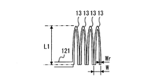
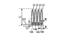
- FIG. 3 is an enlarged view of a range III indicated by a one-dot chain line in FIG.
- FIG. 4 is a diagram illustrating a configuration on the solder surface side of the modified folded dipole antenna according to the second embodiment.
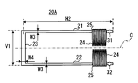
- FIG. 5 is a diagram illustrating a configuration on the component surface side of the modified folded dipole antenna according to the second embodiment.
- FIG. 6 is an enlarged view of a range IV indicated by a one-dot chain line in FIG.
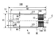
- FIG. 7 is a diagram illustrating a configuration on the solder surface side of the modified folded dipole antenna according to the third embodiment.
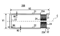
- FIG. 8 is a diagram illustrating a configuration on the component surface side of the modified folded dipole antenna according to the third embodiment.
- FIG. 9 is an enlarged view of a range IX indicated by a one-dot chain line in FIG.
- FIG. 10 is a Smith chart showing the impedance characteristics of the antenna of the first embodiment.
- FIG. 11 is a diagram illustrating the magnitude of the return loss with respect to the frequency of the antenna according to the first embodiment.
- FIG. 12 is a Smith chart showing a comparison of impedance characteristics of the antennas of the first, second, and third embodiments.
- FIG. 13 is a diagram illustrating a configuration on the solder surface side of the modified folded dipole antenna according to the fourth embodiment.
- FIG. 14 is a diagram illustrating a configuration on the component surface side of the modified folded dipole antenna according to the fourth embodiment.
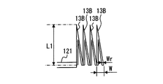
- FIG. 15 is an enlarged view of a range XV indicated by a one-dot chain line in FIG.
- FIG. 16 is a diagram illustrating a configuration on the solder surface side of the modified folded dipole antenna according to the fifth embodiment.
- FIG. 17 is a diagram illustrating a configuration on the component surface side of the modified folded dipole antenna according to the fifth embodiment.
- FIG. 18 is an enlarged view of a range XVIII indicated by a one-dot chain line in FIG.
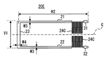
- FIG. 19 is a diagram illustrating a configuration on the solder surface side of the modified folded dipole antenna according to the sixth embodiment.
- FIG. 20 is a diagram illustrating a configuration on the component surface side of the modified folded dipole antenna according to the sixth embodiment.
- FIG. 21 is an enlarged view of a range XXI indicated by a one-dot chain line in FIG.
- FIG. 22 is a diagram illustrating the configuration of the inward protruding portion of the sixth embodiment.
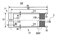
- FIG. 23 is a diagram illustrating a configuration on the solder surface side of the modified folded dipole antenna according to the seventh embodiment.
- FIG. 24 is a diagram illustrating a configuration on the component surface side of the modified folded dipole antenna according to the seventh embodiment.
- FIG. 25 is an enlarged view of a range XXV indicated by a one-dot chain line in FIG.
- FIG. 26 is a diagram illustrating the configuration of the inward protruding portion of the seventh embodiment.
- a modified folded dipole antenna (hereinafter simply referred to as an antenna) of Embodiment 1 has a structure shown in FIGS.
- the antenna according to the first embodiment is configured over both surfaces of a flat substrate (not shown).
- the substrate is common and is made of a dielectric material, such as glass epoxy.
- an antenna feeding side parallel portion 10 is formed by a conductive foil pattern.
- the feeding-side parallel portion 10 includes two L-shaped portions that are symmetrical with respect to the antenna width direction center plane (hereinafter referred to as width direction center plane) C, that is, the first L-shaped portion 11 and the second L-shaped portion 12. Prepare.
- the first L-shaped portion 11 includes a long side portion 111 and a short side portion 112 corresponding to the first side portion and the second side portion, respectively.
- the long side portion 111 is parallel to the center plane C in the width direction.
- the short side portion 112 is shorter than the long side portion 111, is connected to one end of the long side portion 111, and projects vertically from the long side portion 111 in the width direction central plane C direction.
- the second L-shaped portion 12 has the same configuration as that of the first L-shaped portion 11 and includes a long side portion 121 and a short side portion 122 corresponding to the first side portion and the second side portion, respectively.
- the long side portion 121 has the same length and width as the long side portion 111 of the first L-shaped portion 11, and faces the long side portion 111 of the first L-shaped portion 11 across the width direction center plane C.
- the short side portion 122 is shorter than the long side portion 121, is one end of the long side portion 121, and is the same side as the side where the short side portion 112 is connected to the long side portion 111 in the first L-shaped portion 11. It is connected to.
- the short side part 122 protrudes in the width direction center plane C direction perpendicularly from the long side part 121.
- the width and length of the short side portion 122 are the same as the short side portion 112 of the first L-shaped portion 11.
- the first L-shaped portion 11 and the second L-shaped portion 12 have the same shape, and are arranged so that the short side portions 112 and 122 face each other. And the front-end
- the above-mentioned center plane C in the width direction is a plane perpendicular to the solder surface of the substrate and parallel to the long side portion 111 of the first L-shaped portion 11 and the long side portion 121 of the second L-shaped portion 12. Further, the center plane C in the width direction passes through the width direction of the power supply side parallel part 10 and the non-power supply side parallel part 20 (that is, the vertical direction in FIGS. 1 and 2).
- a short-circuit portion 31 that penetrates the substrate vertically is formed.
- a short-circuit portion 32 penetrating the substrate is also formed in the vicinity of the end portion of the other long side portion 121 opposite to the side to which the short side portion 122 is connected.
- These two short-circuit portions 31 and 32 are arranged at positions where the distances from the ends opposite to the side where the short side portions 112 and 122 of the long side portions 111 and 121 are connected to each other are the same. .
- first L-shaped portion 11 and the second L-shaped portion 12 are formed with a plurality of inner protruding portions 13 in a part thereof.
- the inner protruding portion 13 is a straight line of the long side portions 111 and 121 of the first L-shaped portion 11 and the second L-shaped portion 12 in the inner direction surrounded by the first L-shaped portion 11 and the second L-shaped portion 12 in the solder surface. It sticks out from the part.
- Each of the inner protrusions 13 in the present embodiment has a semi-elliptical shape. Therefore, the width of the distal end portion of the inner protruding portion 13 is shorter than the length of the base portion, that is, the length between the two end points, and the width continuously decreases toward the distal end.
- the number of the inner protrusions 13 is twelve for each of the long side portion 111 of the first L-shaped portion 11 and the long side portion 121 of the second L-shaped portion 12. Twelve positions of the inner protrusion 13 are arranged continuously from the vicinity of the short-circuit portion 31 of the long side 111 of the first L-shaped portion 11 toward the short side 112. The same applies to the second L-shaped portion 12 side, and twelve pieces are continuously formed in the direction of the short side portion 122 from the vicinity of the short-circuit portion 32 of the long side portion 121 of the second L-shaped portion 12.
- “continuous” means that the end of one inner projecting portion 13 and the end of another inner projecting portion 13 adjacent to the inner projecting portion 13 are common. Further, in the present embodiment, the positions of both ends of the inner protrusion 13 are in the center line of the long side 121 in the width direction.
- the inner protruding portion 13 is bent from the straight portion of the long side portion 121 at one end, protrudes inward, is folded back at the tip portion, and is connected to the straight portion of the long side portion 121 again at the other end point.
- the width of the base of the inner protrusion 13 is W
- the height is L1
- the line width is Wr.
- the power supply side parallel portion 10 having such a configuration has a length in the longitudinal direction that is the length of the long side portions 111 and 121, and a length in the width direction is V1.
- the long side portions 111 and 121 have a width W1
- the short side portions 112 and 122 have a width W2.
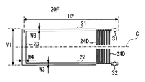
- the length from the end of the long side portions 111 and 121 on the short-circuit portions 31 and 32 side to the center line in the width direction of the short side portions 112 and 122 is defined as H2.
- a non-feed side parallel portion 20 of the antenna is formed by a conductor foil pattern.
- the non-feeding side parallel portion 20 includes a pair of opposed side portions 21 and 22 arranged to face each other, and a connecting side portion 23 that connects one ends of the pair of opposed side portions 21 and 22 to each other.
- the opposing sides 21 and 22 are parallel to each other, and the length and width are the same.
- One end of the short-circuit portion 31 described above is located near the end of the opposite side portion 21 opposite to the side to which the connection side portion 23 is connected.
- one end of another short-circuit portion 32 is located near the end of the opposite side portion 22 opposite to the side to which the connecting side portion 23 is connected.
- the opposing side portion 21 has a length from the end on the short-circuit portion 31 side to the center in the width direction of the connecting side portion 23 as described above, and is the first L-shape of the power supply side parallel portion 10 through the substrate. It faces the long side portion 111 of the portion 11.
- the length from the end on the short-circuit portion 32 side to the center in the width direction of the connecting side portion 23 is H2 in the other opposing side portion 22 as well.
- the facing side portion 22 faces the long side portion 121 of the second L-shaped portion 12 of the power feeding side parallel portion 10 through the substrate.
- variety of these opposing edge parts 21 and 22 is set to W3.
- the connecting side portion 23 is perpendicular to the two opposing side portions 21 and 22, has a longitudinal length V1 and a width W4.
- This connection side part 23 opposes the short side part 112 of the 1st L-shaped part 11 of the electric power feeding side parallel part 10, and the short side part 122 of the 2nd L-shaped part 12 through a board
- an inner protruding portion 24 that protrudes in an inner direction surrounded by the opposing side portions 21 and 22 and the connecting side portion 23 is formed.
- the inner protruding portion 24 has the same shape as the inner protruding portion 13 formed in the power feeding side parallel portion 10, and the inner protruding portion 24 is also semi-elliptical.
- the inner protrusion 24 is the same size as the inner protrusion 13.
- 24 pieces are formed in the same manner as the inner protruding portion 13, and are formed at positions facing the inner protruding portion 13, respectively.
- the impedance adjustment in the antenna of the present embodiment is performed by a method disclosed in Patent Document 1 or a known method. Specifically, the impedance is adjusted by any one of the following methods (1) to (5). (1) Adjusting W1 to W4 while making W2> W1, W3, W4. (2) Adjusting W1 to W4 while satisfying W3> W1, W2, and W4. (3) Fix W3 and W1, and adjust the ratio (W2 / W4). (4) Adjusting W1 to W4 while satisfying W1> W2, W3, W4. (5) Adjust W1 to W4 while making W4> W1, W2, and W3.
- the power supply side parallel portion 10 includes the inner protruding portion 13 that protrudes from the long side portions 111 and 121 of the power supply side parallel portion 10. Further, the non-feeding side parallel portion 20 also includes an inner protruding portion 24 that protrudes from the opposite side portions 21 and 22 of the non-feeding side parallel portion 20. Therefore, the line length of the antenna according to the first embodiment is longer than that in the case where the inner protrusions 13 and 24 are not provided.
- the antenna does not become large. Therefore, the antenna having the same line length can be further downsized as compared with the case where the inner projecting portions 13 and 24 are not provided.
- the inner protrusion parts 13 and 24 can be continuously formed by making the inner protrusion parts 13 and 24 into a semi-elliptical shape. Therefore, since many inner protrusion parts 13 and 24 can be formed in a narrow range, an antenna can be reduced in size especially.
- Embodiment 2 Next, Embodiment 2 will be described.
- elements having the same reference numerals as those used so far are the same as the elements having the same reference numerals in the previous embodiments unless otherwise specified.
- the embodiment described above can be applied to other parts of the configuration.
- the power feeding side parallel portion 10 ⁇ / b> A of the antenna of Embodiment 2 further includes both end connection portions 14 that connect both ends of each inner protrusion 13.
- the non-feed-side parallel portion 20A further includes both end connection portions 25 that connect both ends of each inner protrusion 24 as shown in FIG.
- the power supply side parallel part 10A and the non-power supply side parallel part 20A of the second embodiment are only different from the power supply side parallel part 10 and the non-power supply side parallel part 20 of the first embodiment.
- the both-end connecting portion 14 of the second embodiment has a semi-elliptical shape, and protrudes outward, unlike the inner protruding portion 13.
- the height of the both-end connecting portion 14 is L2 as shown in FIG.
- the configuration of the both-end connecting portion 25 provided in the non-feed-side parallel portion 20A is the same as the both-end connecting portion 14.
- a configuration including both end connection portions 14 and 25 may be used.
- the effect obtained by providing the both end connection portions 14 and 25 will be described in the description of the third embodiment.
- the impedance adjustment is performed by the method described in the first embodiment.
- the power feeding side parallel portion 10 ⁇ / b> B of the antenna according to the third embodiment further includes both end connection portions 14 ⁇ / b> A that connect both ends of each inner protrusion 13.
- the non-feed-side parallel portion 20B further includes both end connection portions 25A that connect both ends of each inner protruding portion 24 as shown in FIG.
- the power supply side parallel part 10B and the non-power supply side parallel part 20B of the third embodiment are only different from the power supply side parallel part 10 and the non-power supply side parallel part 20 of the first embodiment.
- both end connecting portions 14A also connect one end and the other end of the inner protruding portion 13, and have a shape. Is semi-elliptical.
- the both-end connecting portion 14 ⁇ / b> A protrudes inward like the inner protrusion 13.
- the height of the both-end connecting portion 14A is L2 as in the both-end connecting portion 14 of the second embodiment as shown in FIG.
- the configuration of the both-end connecting portion 25A provided in the non-feed-side parallel portion 20B is also the same as the both-end connecting portion 14A.
- impedance adjustment is performed by the method described in the first embodiment.
- FIG. 10 is a Smith chart displayed by calculating the impedance of the antenna according to the first embodiment by simulation.
- the solid line is before impedance adjustment, and the broken line is after impedance adjustment.
- a broken line is an estimated value.
- the solid line is the impedance characteristic of the antenna of the first embodiment, and is the same as the solid line in FIG.
- a broken line is an impedance characteristic of the antenna of the second embodiment, that is, the antenna having the both-end connection portions 14 and 25 protruding outward.
- An alternate long and short dash line is the impedance characteristic of the antenna of the third embodiment, that is, the antenna having both end connecting portions 14A and 25A protruding inward. From FIG. 12, it can be seen that the small resonance points disappear in the second and third embodiments.
- the resonance frequency under the conditions shown in the description of FIG. 10 is 787 MHz in the first embodiment in which only the inner protruding portion 13 is provided, 821 MHz in the second embodiment including both end connecting portions 25 protruding outward, and both end connecting portions protruding inward. In Embodiment 3 with 25A, it was 858 MHz. On the other hand, when the inner protrusion 13 is not provided, the resonance frequency is 1333 MHz.
- the antenna of the first embodiment is 0.59
- the antenna of the second embodiment is 0.62
- the antenna of the third embodiment is 0. .64. Also from these things, it turns out that an antenna can be reduced in size by providing the inner side protrusion part 13 irrespective of the presence or absence of the both end connection parts 25 and 25A.
- the feeding-side parallel portion 10 ⁇ / b> C of the antenna according to the fourth embodiment has an inner protrusion portion 13 ⁇ / b> A formed on the long side portions 111 and 121. Further, as shown in FIG. 14, the inner projecting portion 24 ⁇ / b> A is also formed in the non-feed-side parallel portion 20 ⁇ / b> C.
- the inner protrusion 13A has an isosceles triangle shape. Further, the inner protruding portion 24A of the non-feeding side parallel portion 20C has the same shape as the inner protruding portion 13A shown in FIG.
- the shape of the inner protrusions 13A and 24A are different from those of the above-described embodiment, and the number, position, and size of the inner protrusions 13A and 24A are the same as those of the inner protrusion 13 of the above-described embodiment. Is the same. Further, the line width Wr is also the same as that of the inward protruding portion 13 of the above-described embodiment.
- the tip is a point, so the width of the tip is shorter than the length W of the base, and the width continuously decreases toward the tip. Become. Therefore, as shown in FIG. 15, the inner protrusions 13A and 24A can be continuously formed even if the inner protrusions 13A and 24A have an isosceles triangle shape.
- the antenna can be particularly miniaturized.
- the impedance adjustment is performed by the method described in the first embodiment.
- the feeding-side parallel portion 10 ⁇ / b> D of the antenna according to the fifth embodiment has an inner protrusion 13 ⁇ / b> B formed on the long side portions 111 and 121.
- the inner protrusion 24B is also formed in the non-feeding side parallel portion 20D.
- the inner protruding portion 13B has a right triangle shape. Further, the inner protruding portion 24B of the non-feeding side parallel portion 20D has the same shape as the inner protruding portion 13B shown in FIG.
- Embodiment 5 is different from the above-described embodiment only in the shape of the inner protrusions 13B and 24B, and the number, position, and size of the inner protrusions 13B and 24B are the same as those in the above-described embodiment.
- the tip is a point, so the width of the tip is shorter than the length W of the base, and the width continuously decreases toward the tip. . Therefore, as shown in FIG. 18, the inner protrusions 13B and 24B can be continuously formed even if the inner protrusions 13B and 24B are formed in a right triangle shape.
- the antenna can be particularly miniaturized.
- the impedance adjustment is performed by the method described in the first embodiment.
- the inner side protruding portion 13 ⁇ / b> C is formed on the long side portions 111 and 121. Further, as shown in FIG. 20, the inner projecting portion 24 ⁇ / b> C is also formed in the non-feeding side parallel portion 20 ⁇ / b> E.
- the inner protruding portion 13C has a step shape.
- the height L1 and the line width Wr of the inner protrusion 13C are the same as those of the inner protrusions 13, 13A, 13B in the above-described embodiment.
- the width of the repeating unit is W which is the same as the width of the inner protrusions 13, 13 ⁇ / b> A, 13 ⁇ / b> B of the above-described embodiment.
- the number and position of the inner protrusions 13C are the same as those in the above-described embodiment.
- the inner protruding portion 24C of the non-feeding side parallel portion 20E has the same shape, size, and arrangement as the inner protruding portion 13C.
- one inner projecting portion 13C, 24C includes first long perpendicular portions 13C1, 24C1, tip line portions 13C2, 24C2, first short perpendicular portions 13C3, 24C3, intermediate line portion 13C4, 24C4 and second short perpendicular portions 13C5 and 24C5.
- the first long perpendicular portions 13C1 and 24C1 extend toward the center plane C in the antenna width direction from one end point e of the inner protruding portions 13C and 24C to the tip of the inner protruding portions 13C and 24C.
- the distal end line portions 13C2 and 24C2 are connected at one end to the distal ends of the first long perpendicular portions 13C1 and 24C1 and are parallel to the center plane C in the antenna width direction.
- the first short perpendicular portions 13C3 and 24C3 have one ends connected to the tip end wire portions 13C2 and 24C2, perpendicular to the antenna width direction center plane C and separated from the antenna width direction center plane C from the tip end line portions 13C2 and 24C2. It extends in the direction to do.
- the first short perpendicular portions 13C3 and 24C3 are shorter than the first long perpendicular portions 13C1 and 24C1.
- the intermediate line portions 13C4 and 24C4 are connected at one end to the first short perpendicular portions 13C3 and 24C3, and are parallel to the center plane C in the antenna width direction from the first short perpendicular portions 13C3 and 24C3, and the first long perpendicular portion 13C1 and It extends on the opposite side to 24C1.
- the second short perpendicular portions 13C5, 24C5 are connected to the intermediate line portions 13C4, 24C4 at one end, and the other end is an end point of the inner projecting portion opposite to the side where the first long perpendicular portions 13C1, 24C1 are connected. e, which is perpendicular to the center plane C in the antenna width direction.
- the second short perpendicular portions 13C5 and 24C5 are shorter than the first long perpendicular portions 13C1 and 24C1.
- the inner protrusions 13C and 24C having the above configuration are connected to the adjacent inner protrusions 13C and 24C through the short connection lines 15 and 26, respectively.
- the short connection lines 15 and 26 are formed such that the outer sides are positioned on the center lines in the width direction of the long sides 111 and 121 and the opposing sides 21 and 22 not shown in FIG.
- the length of the inner projecting portions 13C and 24C is longer than the case where there are no inner projecting portions 13C and 24C, so the antenna is downsized. be able to.
- impedance adjustment is performed by the method described in the first embodiment.
- the feeding-side parallel portion 10F of the antenna according to the seventh embodiment has an inner protrusion portion 13D formed on the long side portions 111 and 121. Further, as shown in FIG. 24, an inner protrusion 24D is also formed in the non-feeding side parallel portion 20F.
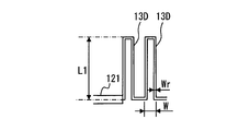
- the inner protrusion 13D has a right-angled bent shape having two right-angled bent points.
- the height L1 and the line width Wr of the inner protrusion 13D are the same as the inner protrusions 13, 13A, 13B, and 13C of the above-described embodiment.
- the width of the repeating unit is W which is the same as the width of the inner protrusions 13, 13 ⁇ / b> A, 13 ⁇ / b> B of the above-described embodiment.
- the number and position of the inner protrusion 13D are the same as those in the above-described embodiment.
- the inner protruding portion 24D of the non-feeding side parallel portion 20E has the same shape, size, and arrangement as the inner protruding portion 13D.
- one inner projecting portion 13D, 24D includes a first perpendicular portion 13D1, 24D1, a leading end portion 13D2, 24D2, and a second perpendicular portion 13D3, 24D3.
- the first perpendicular portions 13D1 and 24D1 extend toward the center plane C in the antenna width direction from one end point e of the inner protruding portions 13D and 24D to the tip of the inner protruding portions 13D and 24D.
- the tip line portions 23D2 and 24D2 are connected at one end to the tips of the first perpendicular portions 13D1 and 24D1, and are parallel to the center plane C in the antenna width direction.
- the second perpendicular portions 13D3 and 24D3 are connected at one end to the tip line portions 13D2 and 24D2, and the other end is an end point of the inner protruding portions 13D and 24D opposite to the first perpendicular portions 13D1 and 24D1, It is perpendicular to the center plane C in the antenna width direction.
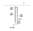
- the inner protruding portions 13D and 24D having the above-described configuration are connected to the adjacent inner protruding portions 13D and 24D through the short connection lines 16 and 27, respectively.
- the short connection lines 16 and 27 are formed so that the outer sides are positioned on the center lines in the width direction of the long sides 111 and 121 and the opposing sides 21 and 22 not shown in FIG.
- the lengths of the short connection lines 16 and 27 are the same W as the widths of the inner protrusions 13D and 24D. Therefore, in the case of Embodiment 7, the width of the repeating unit of the inner protrusions 13D and 24D is 2W.
- the impedance adjustment is performed by the method described in the first embodiment.
- the line length LL (13) of the two (2 W width) semi-elliptical inner protrusions 13 can be expressed by the following equation 1 from the elliptic integral equation.
- the line length LL (13A) of the two (2 W width) isosceles triangular inner protrusions 13A can be expressed by the following equation 2.
- the line length LL (13D) of one repeating unit (2 W width) composed of the right-angle bent inner protruding portion 13D and the short connection line 16 can be expressed by the following Equation 3.
- LL (13D) 2 (W + L1) (Formula 3)
- LL (13) 24.2 mm
- LL (13A) 24.0 mm
- LL (13D) 13.2 mm.
- the line length ratio of the semi-elliptical inner protrusion 13 and the isosceles inner protrusion 13A is as follows. Both are 1.8.
- the semi-elliptical inner protruding portion 13 and the isosceles triangular inner protruding portion 13A can continuously form the inner protruding portions 13 and 13A as shown in FIGS. Therefore, the line length ratio can be increased as compared with the inner side protruding portion 13D having a right-angle bent shape.
- both end connection portions 14 and 25 of the second embodiment protrude outward
- both end connection portions 14A and 25A of the third embodiment protrude inward. Since both ends may protrude either inside or outside, the both end connecting portion may be the middle of the shapes of the second and third embodiments, that is, the both end connecting portion may be a straight line.
- both ends of the inner protruding portions 13A to 13D and 24A to 24D having other shapes may be connected by the both end connecting portions 14, 14A, 25, and 25A.
- the inner protrusions There are no particular limitations on the number and position of the inner protrusions. For example, you may arrange
- the first L-shaped portion 11 and the second L-shaped portion 12 include the long side portions 111 and 121 as the first side portions and the short side portions 112 and 122 as the second side portions, respectively.
- the relationship between the lengths of the first side and the second side may be opposite to that of the above-described embodiment. That is, the length of the second side may be longer than that of the first side. Further, the first side and the second side may have the same length.
Landscapes
- Details Of Aerials (AREA)
Abstract
Description
以下、本開示の実施形態を図面に基づいて説明する。実施形態1の変形折り返しダイポールアンテナ(以下、単にアンテナ)は、図1、2に示す構造を有する。実施形態1のアンテナは図示しない平板状の基板の両面にわたって構成される。基板は一般的なものであり、誘電材料、たとえば、ガラスエポキシ製である。
図1に示す基板のはんだ面には、アンテナの給電側平行部10が導体箔パターンにより形成されている。給電側平行部10は、アンテナ幅方向中心面(以下、幅方向中心面)Cに対して対称となっている2つのL字部、すなわち、第1L字部11と第2L字部12とを備える。
図2に示す基板の部品面には、アンテナの非給電側平行部20が導体箔パターンにより形成されている。非給電側平行部20は、互いに対向して配置された一対の対向辺部21、22と、その一対の対向辺部21、22の一端を互いに連結する連結辺部23を備える。
本実施形態のアンテナにおけるインピーダンス調整は、特許文献1に開示の方法や公知の方法により行う。具体的には下記(1)~(5)のいずれかの方法により、インピーダンス調整を行う。
(1)W2>W1、W3、W4となるようにしつつ、それらW1~W4を調整する。
(2)W3>W1、W2、W4となるようにしつつ、それらW1~W4を調整する。
(3)W3、W1を固定し、比(W2/W4)を調整する。
(4)W1>W2、W3、W4となるようにしつつ、それらW1~W4を調整する。
(5)W4>W1、W2、W3となるようにしつつ、それらW1~W4を調整する。
以上、説明した実施形態1によれば、給電側平行部10は、その給電側平行部10の長辺部111、121から突き出す内側突き出し部13を備えている。また、非給電側平行部20も、その非給電側平行部20の対向辺部21、22から突き出す内側突き出し部24を備えている。よって、それら内側突き出し部13、24がない場合よりも、実施形態1のアンテナは線路長が長くなる。
次に実施形態2を説明する。この実施形態2以下の説明において、それまでに使用した符号と同一番号の符号を有する要素は、特に言及する場合を除き、それ以前の実施形態における同一符号の要素と同一である。また、構成の一部のみを説明している場合、構成の他の部分については先に説明した実施形態を適用することができる。
実施形態3のアンテナの給電側平行部10Bは、図7に示すように、各内側突き出し部13の両端を接続する両端接続部14Aをさらに備える。また、非給電側平行部20Bは、図8に示すように、各内側突き出し部24の両端を接続する両端接続部25Aをさらに備える。これらの点において、実施形態3の給電側平行部10B、非給電側平行部20Bは、実施形態1の給電側平行部10、非給電側平行部20と相違するのみである。
実施形態2、3のように、両端接続部14、14A、25、25Aを備える効果について説明する。
実施形態4のアンテナの給電側平行部10Cは、図13に示すように、長辺部111、121に内側突き出し部13Aが形成されている。また、図14に示すように、非給電側平行部20Cにも内側突き出し部24Aが形成されている。
実施形態5のアンテナの給電側平行部10Dは、図16に示すように、長辺部111、121に内側突き出し部13Bが形成されている。また、図17に示すように、非給電側平行部20Dにも内側突き出し部24Bが形成されている。
実施形態6のアンテナの給電側平行部10Eは、図19に示すように、長辺部111、121に内側突き出し部13Cが形成されている。また、図20に示すように、非給電側平行部20Eにも内側突き出し部24Cが形成されている。
実施形態7のアンテナの給電側平行部10Fは、図23に示すように、長辺部111、121に内側突き出し部13Dが形成されている。また、図24に示すように、非給電側平行部20Fにも内側突き出し部24Dが形成されている。
ここで、実施形態1、4、7に開示の内側突き出し部13、13A、13D、すなわち、半楕円形状、二等辺三角形状、直角折れ曲がり形状の内側突き出し部13、13A、13Dの線路長を比較する。


W=0.6mm、L1=6mmとして、各線路長LL(13)、LL(13A)、LL(13D)を算出すると、LL(13)=24.2mm、LL(13A)=24.0mm、LL(13D)=13.2mmとなる。
以上、本開示の実施形態を説明したが、本開示は上述の実施形態に限定されるものではなく、下記の実施形態も本開示の技術的範囲に含まれ、さらに、下記以外にも要旨を逸脱しない範囲内で種々変更して実施することができる。
Claims (11)
- 給電点を有する給電側平行部(10)と、
給電点を有さず、前記給電側平行部と平行に配置された非給電側平行部(20)と、
前記給電側平行部および前記非給電側平行部よりも短い長さを有して、前記給電側平行部の両端と前記非給電側平行部の両端とをそれぞれ接続する一対の短絡部(31、32)とを備え、
前記非給電側平行部は、互いに対向して配置された一対の対向辺部(21、22)と、前記一対の対向辺部の一端を互いに連結する連結辺部(23)を備え、
前記給電側平行部は、前記非給電側平行部の一方の対向辺部および前記連結辺部の一部にそれぞれ対向する第1辺部および第2辺部を有する第1L字部(11)と、前記非給電側平行部の他方の対向辺部および前記連結辺部の一部にそれぞれ対向する第1辺部および第2辺部を有する第2L字部(12)とを備える、変形折り返しダイポールアンテナであって、
前記給電側平行部および前記非給電側平行部の少なくとも一方は、一部に、前記給電側平行部あるいは前記非給電側平行部によって囲われる内側方向に突き出している内側突き出し部(13、13A、13B、13C、13D、24、24A、24B、24C、24D)を少なくとも一つ備える変形折り返しダイポールアンテナ。 - 請求項1において、
前記内側突き出し部(13、13A、13B、13C、24、24A、24B、24C)は、先端部の幅が基部の長さよりも短い変形折り返しダイポールアンテナ。 - 請求項2において、
前記内側突き出し部(13、13A、13B、24、24A、24B)は、先端へ向かうほど連続的に幅が狭くなる変形折り返しダイポールアンテナ。 - 請求項3において、
前記内側突き出し部(13、24)が半楕円形状である変形折り返しダイポールアンテナ。 - 請求項3において、
前記内側突き出し部(13A、13B、24A、24B)が三角形状である変形折り返しダイポールアンテナ。 - 請求項3~5のいずれか1項において、
前記内側突き出し部を複数備え、
複数の内側突き出し部のうち少なくとも一組の内側突き出し部は互いに隣り合っており、一方の内側突き出し部の端点と他方の内側突き出し部の端点とが共通している変形折り返しダイポールアンテナ。 - 請求項2において、
前記内側突き出し部(13C、24C)は、
前記給電側平行部を含む面および前記非給電側平行部を含む面に対して垂直であり、前記給電側平行部および前記非給電側平行部の幅方向中心を通る平面であるアンテナ幅方向中心面に向かって、前記内側突き出し部の一方の端点から垂直に先端まで延びる第1長垂線部(13C1、24C1)と、
前記第1長垂線部の先端側の端に一端が連結され、前記アンテナ幅方向中心面に平行な先端線部(13C2、24C2)と、
前記先端線部に一端が連結され、前記先端線部から、前記アンテナ幅方向中心面に垂直に、かつ、前記アンテナ幅方向中心面から離隔する方向に延びる第1短垂線部(13C3、24C3)と、
前記第1短垂線部に一端が連結され、前記第1短垂線部から、前記アンテナ幅方向中心面に平行、かつ、前記第1長垂線部とは反対側に延びる中間線部(13C4、24C4)と、
前記中間線部に一端が連結され、他端が、前記第1長垂線部が連結されている側とは反対側の前記内側突き出し部の端点となっており、前記アンテナ幅方向中心面に垂直な第2短垂線部(13C5、24C5)と、
を備えるステップ形状である変形折り返しダイポールアンテナ。 - 請求項1において、
前記内側突き出し部(13D、24D)は、
前記給電側平行部を含む面および前記非給電側平行部を含む面に対して垂直であり、前記給電側平行部および前記非給電側平行部の幅方向中心を通る平面であるアンテナ幅方向中心面に向かって、前記内側突き出し部の一方の端点から垂直に先端まで延びる第1垂線部(13D1、24D1)と、
前記第1垂線部の先端側の端に一端が連結され、前記アンテナ幅方向中心面に平行な先端線部(13D2、24D2)と、
前記先端線部に一端が連結され、他端が、前記第1垂線部とは反対側の前記内側突き出し部の端点となっており、前記アンテナ幅方向中心面に垂直な第2垂線部(13D3、24D3)と、
を備える変形折り返しダイポールアンテナ。 - 請求項1~8のいずれか1項において、
前記内側突き出し部の両端点の間を電気的に接続する両端接続部(14、14A、25、25A)をさらに備える変形折り返しダイポールアンテナ。 - 請求項9において、
前記両端接続部(14A、25A)が、前記内側突き出し部と同方向に突き出している変形折り返しダイポールアンテナ。 - 請求項9において、
前記両端接続部(14、25)が、前記内側突き出し部とは反対方向に突き出している変形折り返しダイポールアンテナ。
Priority Applications (3)
| Application Number | Priority Date | Filing Date | Title |
|---|---|---|---|
| RU2016116920A RU2627013C1 (ru) | 2013-10-07 | 2014-09-24 | Деформированная петлевая дипольная антенна |
| US15/027,052 US10224633B2 (en) | 2013-10-07 | 2014-09-24 | Deformed folded dipole antenna |
| DE112014004613.2T DE112014004613B4 (de) | 2013-10-07 | 2014-09-24 | Deformierte gefaltete Dipolantenne |
Applications Claiming Priority (2)
| Application Number | Priority Date | Filing Date | Title |
|---|---|---|---|
| JP2013-210333 | 2013-10-07 | ||
| JP2013210333A JP6131816B2 (ja) | 2013-10-07 | 2013-10-07 | 変形折り返しダイポールアンテナ |
Publications (1)
| Publication Number | Publication Date |
|---|---|
| WO2015052883A1 true WO2015052883A1 (ja) | 2015-04-16 |
Family
ID=52812719
Family Applications (1)
| Application Number | Title | Priority Date | Filing Date |
|---|---|---|---|
| PCT/JP2014/004876 Ceased WO2015052883A1 (ja) | 2013-10-07 | 2014-09-24 | 変形折り返しダイポールアンテナ |
Country Status (5)
| Country | Link |
|---|---|
| US (1) | US10224633B2 (ja) |
| JP (1) | JP6131816B2 (ja) |
| DE (1) | DE112014004613B4 (ja) |
| RU (1) | RU2627013C1 (ja) |
| WO (1) | WO2015052883A1 (ja) |
Families Citing this family (3)
| Publication number | Priority date | Publication date | Assignee | Title |
|---|---|---|---|---|
| JP6304224B2 (ja) | 2015-07-31 | 2018-04-04 | 株式会社デンソー | 小型アンテナ及び計算装置 |
| US10468762B1 (en) * | 2016-10-24 | 2019-11-05 | Remarkable Technologies, Inc. | Versatile antenna wire and methods of manufacturing |
| JP2023060425A (ja) | 2021-10-18 | 2023-04-28 | ミツミ電機株式会社 | アンテナ装置及びアンテナシステム |
Citations (4)
| Publication number | Priority date | Publication date | Assignee | Title |
|---|---|---|---|---|
| JP2008167467A (ja) * | 2008-01-25 | 2008-07-17 | Furukawa Electric Co Ltd:The | 小型アンテナ |
| JP2010258731A (ja) * | 2009-04-24 | 2010-11-11 | Denso Wave Inc | Rfidタグ読取装置 |
| JP2011130411A (ja) * | 2009-11-20 | 2011-06-30 | Denso Corp | 変形折返しダイポールアンテナ及びそのインピーダンス調整方法、アンテナ装置 |
| JP2013131839A (ja) * | 2011-12-20 | 2013-07-04 | Mitsubishi Cable Ind Ltd | 折返しダイポールアンテナ |
Family Cites Families (8)
| Publication number | Priority date | Publication date | Assignee | Title |
|---|---|---|---|---|
| US4381566A (en) | 1979-06-14 | 1983-04-26 | Matsushita Electric Industrial Co., Ltd. | Electronic tuning antenna system |
| JP4007332B2 (ja) | 2004-03-11 | 2007-11-14 | 株式会社デンソー | 統合アンテナ |
| JP4311576B2 (ja) * | 2005-11-18 | 2009-08-12 | ソニー・エリクソン・モバイルコミュニケーションズ株式会社 | 折り返しダイポールアンテナ装置および携帯無線端末 |
| JP5176465B2 (ja) | 2006-10-05 | 2013-04-03 | 大日本印刷株式会社 | 非接触icタグと非接触icタグのエンコード方法 |
| JP4722064B2 (ja) * | 2007-02-27 | 2011-07-13 | ブラザー工業株式会社 | アンテナ及び無線タグ |
| JP5304580B2 (ja) * | 2009-10-02 | 2013-10-02 | 株式会社村田製作所 | 無線icデバイス |
| GB2500136B (en) | 2010-10-15 | 2015-02-18 | Microsoft Corp | Parasitic folded loop antenna |
| DE102012221940B4 (de) | 2012-11-30 | 2022-05-12 | Robert Bosch Gmbh | Modul zur drahtlosen Kommunikation und Verfahren zum Herstellen eines Moduls zur drahtlosen Kommunikation |
-
2013
- 2013-10-07 JP JP2013210333A patent/JP6131816B2/ja not_active Expired - Fee Related
-
2014
- 2014-09-24 US US15/027,052 patent/US10224633B2/en active Active
- 2014-09-24 WO PCT/JP2014/004876 patent/WO2015052883A1/ja not_active Ceased
- 2014-09-24 DE DE112014004613.2T patent/DE112014004613B4/de not_active Expired - Fee Related
- 2014-09-24 RU RU2016116920A patent/RU2627013C1/ru active
Patent Citations (4)
| Publication number | Priority date | Publication date | Assignee | Title |
|---|---|---|---|---|
| JP2008167467A (ja) * | 2008-01-25 | 2008-07-17 | Furukawa Electric Co Ltd:The | 小型アンテナ |
| JP2010258731A (ja) * | 2009-04-24 | 2010-11-11 | Denso Wave Inc | Rfidタグ読取装置 |
| JP2011130411A (ja) * | 2009-11-20 | 2011-06-30 | Denso Corp | 変形折返しダイポールアンテナ及びそのインピーダンス調整方法、アンテナ装置 |
| JP2013131839A (ja) * | 2011-12-20 | 2013-07-04 | Mitsubishi Cable Ind Ltd | 折返しダイポールアンテナ |
Also Published As
| Publication number | Publication date |
|---|---|
| JP2015076678A (ja) | 2015-04-20 |
| US20160240926A1 (en) | 2016-08-18 |
| RU2627013C1 (ru) | 2017-08-02 |
| DE112014004613T5 (de) | 2016-07-14 |
| JP6131816B2 (ja) | 2017-05-24 |
| DE112014004613B4 (de) | 2021-08-12 |
| US10224633B2 (en) | 2019-03-05 |
Similar Documents
| Publication | Publication Date | Title |
|---|---|---|
| JP4747179B2 (ja) | アンテナ装置及びそれを用いた通信装置 | |
| US20100171676A1 (en) | Antenna element | |
| JP2005079970A (ja) | アンテナ装置 | |
| JP2012142793A (ja) | アンテナ装置 | |
| US8305284B2 (en) | Antenna assembly with three-dimension connecting element | |
| US8354963B2 (en) | Low-profile three-dimensional antenna | |
| CN1716690A (zh) | 天线装置 | |
| JP6131816B2 (ja) | 変形折り返しダイポールアンテナ | |
| US9466878B2 (en) | Multi-band antenna | |
| JP2013211797A (ja) | 通信端末 | |
| US9660329B2 (en) | Directional antenna | |
| CN103022643B (zh) | 低高度天线装置 | |
| CN101567486A (zh) | 复合天线 | |
| JP6960588B2 (ja) | マルチバンド対応アンテナ及び無線通信装置 | |
| US20220110212A1 (en) | Flexible circuit board and wireless terminal comprising same | |
| JP2001320225A (ja) | アンテナ装置 | |
| US7307588B2 (en) | Ultra wide bandwidth planar antenna | |
| JP4563959B2 (ja) | 車載アンテナ及びその搭載方法 | |
| JP2010016460A (ja) | 八木形アンテナ | |
| JP4532587B2 (ja) | 広帯域アンテナ | |
| JP2011193432A (ja) | ボウタイアンテナ | |
| US20160268692A1 (en) | Antenna device | |
| US20150061948A1 (en) | Electronic device | |
| JP5528686B2 (ja) | メアンダラインアンテナ | |
| JP4981822B2 (ja) | 広帯域アンテナ |
Legal Events
| Date | Code | Title | Description |
|---|---|---|---|
| 121 | Ep: the epo has been informed by wipo that ep was designated in this application |
Ref document number: 14852456 Country of ref document: EP Kind code of ref document: A1 |
|
| WWE | Wipo information: entry into national phase |
Ref document number: 15027052 Country of ref document: US |
|
| WWE | Wipo information: entry into national phase |
Ref document number: 112014004613 Country of ref document: DE Ref document number: 1120140046132 Country of ref document: DE |
|
| ENP | Entry into the national phase |
Ref document number: 2016116920 Country of ref document: RU Kind code of ref document: A |
|
| 122 | Ep: pct application non-entry in european phase |
Ref document number: 14852456 Country of ref document: EP Kind code of ref document: A1 |