WO2015049987A1 - 硫化物固体電解質材料、電池および硫化物固体電解質材料の製造方法 - Google Patents
硫化物固体電解質材料、電池および硫化物固体電解質材料の製造方法 Download PDFInfo
- Publication number
- WO2015049987A1 WO2015049987A1 PCT/JP2014/074566 JP2014074566W WO2015049987A1 WO 2015049987 A1 WO2015049987 A1 WO 2015049987A1 JP 2014074566 W JP2014074566 W JP 2014074566W WO 2015049987 A1 WO2015049987 A1 WO 2015049987A1
- Authority
- WO
- WIPO (PCT)
- Prior art keywords
- solid electrolyte
- sulfide solid
- electrolyte material
- electrode active
- active material
- Prior art date
- Legal status (The legal status is an assumption and is not a legal conclusion. Google has not performed a legal analysis and makes no representation as to the accuracy of the status listed.)
- Ceased
Links
Images


Classifications
-
- H—ELECTRICITY
- H01—ELECTRIC ELEMENTS
- H01M—PROCESSES OR MEANS, e.g. BATTERIES, FOR THE DIRECT CONVERSION OF CHEMICAL ENERGY INTO ELECTRICAL ENERGY
- H01M10/00—Secondary cells; Manufacture thereof
- H01M10/05—Accumulators with non-aqueous electrolyte
- H01M10/056—Accumulators with non-aqueous electrolyte characterised by the materials used as electrolytes, e.g. mixed inorganic/organic electrolytes
- H01M10/0561—Accumulators with non-aqueous electrolyte characterised by the materials used as electrolytes, e.g. mixed inorganic/organic electrolytes the electrolyte being constituted of inorganic materials only
- H01M10/0562—Solid materials
-
- H—ELECTRICITY
- H01—ELECTRIC ELEMENTS
- H01B—CABLES; CONDUCTORS; INSULATORS; SELECTION OF MATERIALS FOR THEIR CONDUCTIVE, INSULATING OR DIELECTRIC PROPERTIES
- H01B1/00—Conductors or conductive bodies characterised by the conductive materials; Selection of materials as conductors
- H01B1/06—Conductors or conductive bodies characterised by the conductive materials; Selection of materials as conductors mainly consisting of other non-metallic substances
- H01B1/10—Conductors or conductive bodies characterised by the conductive materials; Selection of materials as conductors mainly consisting of other non-metallic substances sulfides
-
- H—ELECTRICITY
- H01—ELECTRIC ELEMENTS
- H01M—PROCESSES OR MEANS, e.g. BATTERIES, FOR THE DIRECT CONVERSION OF CHEMICAL ENERGY INTO ELECTRICAL ENERGY
- H01M10/00—Secondary cells; Manufacture thereof
- H01M10/05—Accumulators with non-aqueous electrolyte
- H01M10/052—Li-accumulators
- H01M10/0525—Rocking-chair batteries, i.e. batteries with lithium insertion or intercalation in both electrodes; Lithium-ion batteries
-
- H—ELECTRICITY
- H01—ELECTRIC ELEMENTS
- H01M—PROCESSES OR MEANS, e.g. BATTERIES, FOR THE DIRECT CONVERSION OF CHEMICAL ENERGY INTO ELECTRICAL ENERGY
- H01M2300/00—Electrolytes
- H01M2300/0017—Non-aqueous electrolytes
- H01M2300/0065—Solid electrolytes
- H01M2300/0068—Solid electrolytes inorganic
-
- Y—GENERAL TAGGING OF NEW TECHNOLOGICAL DEVELOPMENTS; GENERAL TAGGING OF CROSS-SECTIONAL TECHNOLOGIES SPANNING OVER SEVERAL SECTIONS OF THE IPC; TECHNICAL SUBJECTS COVERED BY FORMER USPC CROSS-REFERENCE ART COLLECTIONS [XRACs] AND DIGESTS
- Y02—TECHNOLOGIES OR APPLICATIONS FOR MITIGATION OR ADAPTATION AGAINST CLIMATE CHANGE
- Y02E—REDUCTION OF GREENHOUSE GAS [GHG] EMISSIONS, RELATED TO ENERGY GENERATION, TRANSMISSION OR DISTRIBUTION
- Y02E60/00—Enabling technologies; Technologies with a potential or indirect contribution to GHG emissions mitigation
- Y02E60/10—Energy storage using batteries
Definitions
- the present invention relates to a sulfide solid electrolyte material having good ion conductivity.
- lithium batteries currently on the market use an electrolyte containing a flammable organic solvent, it is possible to install safety devices that suppress the temperature rise during short circuits and to improve the structure and materials to prevent short circuits. Necessary.
- a lithium battery in which the electrolyte is changed to a solid electrolyte layer to make the battery completely solid does not use a flammable organic solvent in the battery, so the safety device can be simplified, and manufacturing costs and productivity can be reduced. It is considered excellent.
- Patent Document 1 discloses a sulfide solid electrolyte material using a raw material composition containing Li 2 S and a sulfide of an element belonging to Group 14 or Group 15 (eg, P 2 S 5 ). Has been.
- JP 2010-199033 A International Publication No. 2011/118801
- the present invention has been made in view of the above circumstances, and a main object thereof is to provide a sulfide solid electrolyte material having good ion conductivity.
- the 2 [Theta] 29.58 diffraction intensity of the peak of ° ⁇ 0.50 ° and I a
- the diffraction intensity of the peak of the 2 ⁇ 27.33 ° ⁇ 0.50 ° the upon the I B
- the value of I B / I a is less than 1
- the mole fraction of the P element to a total of the Si element and the P element (P / (Si + P) ) is 0.5 ⁇ P / (Si + P) ⁇ 0.7
- the sulfide solid electrolyte material is characterized in that the molar fraction of the K element (K / (Li + K)) satisfies 0 ⁇ K / (Li + K) ⁇ 0.1.
- the octahedron O composed of Li element and S elements, M a element and the tetrahedron T 1 composed of S elements, M b element and tetrahedron T consists S elements
- the tetrahedron T 1 and the octahedron O share a ridge
- the tetrahedron T 2 and the octahedron O mainly contain a crystal structure sharing a vertex
- the Ma element and at least one of the M b element comprises a Si element comprises at least one of P element of the M a element and the M b element, at least one of the octahedron O
- the molar fraction (P / (Si + P)) of the P element with respect to the sum of the Si element and the P element is 0.5 ⁇ P / (Si + P) ⁇ 0.7 and the above Li source Provided is a sulfide solid
- a sulfide solid electrolyte material having good ion conductivity can be obtained. .
- at least one of the positive electrode active material layer, the negative electrode active material layer, and the electrolyte layer contains the sulfide solid electrolyte material described above.
- a high output battery can be obtained by using the above-described sulfide solid electrolyte material.
- a method for producing the sulfide solid electrolyte material described above wherein the ionized by mechanical milling using the raw material composition containing the components of the sulfide solid electrolyte material.
- Sulfurization comprising: an ion conductive material synthesis step for synthesizing a conductive material; and a heating step for obtaining the sulfide solid electrolyte material by heating the amorphous ion conductive material.
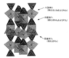
- FIG. 1 is a perspective view explaining an example of the crystal structure of the sulfide solid electrolyte material of this invention. It is a schematic sectional drawing which shows an example of the battery of this invention. It is explanatory drawing which shows an example of the manufacturing method of the sulfide solid electrolyte material of this invention.
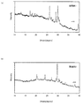
- 2 is an X-ray diffraction spectrum of a sulfide solid electrolyte material obtained in Examples 1 and 2.
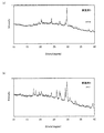
- FIG. 3 is an X-ray diffraction spectrum of the sulfide solid electrolyte material obtained in Examples 3 and 4.
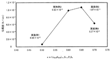
- FIG. 3 is a measurement result of Li ion conductivity of the sulfide solid electrolyte material obtained in Examples 1 to 4.
- the sulfide solid electrolyte material of the present invention will be described.
- the sulfide solid electrolyte material of the present invention can be roughly divided into two embodiments. Therefore, the sulfide solid electrolyte material of the present invention will be described separately for the first embodiment and the second embodiment.
- the LiGePS-based sulfide solid electrolyte material described in Patent Document 2 is an X-ray diffraction measurement using CuK ⁇ rays.
- has a peak in the vicinity of 2 ⁇ 29.58 °.
- the crystal phase having this peak is referred to as crystal phase A.
- the sulfide solid electrolyte material of the first embodiment is considered to have a crystal phase similar to the crystal phase A.
- the crystal phase having this peak is referred to as crystal phase B.
- the crystal phase B is a crystal phase having lower ion conductivity than the crystal phase A described above.
- the sulfide solid electrolyte material of the first embodiment may have a crystal phase similar to the crystal phase B.
- the sulfide solid electrolyte material of the first embodiment preferably has a high proportion of the crystal phase A having high ion conductivity.
- the value of I B / I A is preferably smaller, specifically, preferably 0.55 or less, more preferably 0.45 or less, and 0.25 or less. More preferably, it is particularly preferably 0.15 or less, and extremely preferably 0.07 or less.
- the value of I B / I A is preferably 0.
- the sulfide solid electrolyte material of the first embodiment contains at least Li element, K element, Si element, P element, and S element.
- the molar fraction (P / (Si + P)) of the P element with respect to the sum of the Si element and the P element is usually 0.5 or more, and preferably 0.6 or more.
- the molar fraction is too small, that is, when the Si element content is relatively large, the atomic size of the Si element is small, so that a narrow conduction path is formed with a large distortion of the crystal lattice. This is because there is a possibility that a highly conductive sulfide solid electrolyte material cannot be obtained.
- the molar fraction (P / (Si + P)) is usually 0.7 or less, preferably 0.69 or less, and more preferably 0.65 or less.
- the molar fraction is too large, that is, when the Si element content is relatively small, the expansion of the crystal lattice caused by the inclusion of the K element is not sufficiently suppressed, and the above-described crystalline phase A having high ion conductivity. This is because it is difficult to maintain the structure, and as a result, a sulfide solid electrolyte material may not be obtained.
- the molar fraction can be obtained by, for example, obtaining a mass distribution by ICP (radio frequency inductively coupled plasma) emission spectrometry and dividing by the atomic weight.
- the molar fraction of K element (K / (Li + K)) relative to the total of Li element and K element is not particularly limited as long as it is usually larger than 0. It is preferable that it is 0.01 or more.
- the mole fraction is too small, that is, when the content of K element is relatively small, the distortion of the crystal lattice caused by containing Si element having a small atomic size becomes large, and a narrow conduction path is formed. As a result, a sulfide solid electrolyte material having high ion conductivity may not be obtained.
- the molar fraction (K / (Li + K)) is not particularly limited as long as the above-described crystal phase A can be formed.
- the molar fraction (K / (Li + K)) is preferably 0.09 or less.
- the molar fraction is too large, that is, when the content of K element is relatively large, the expansion of the crystal lattice caused by containing K element is not sufficiently suppressed, and the above-described crystal phase A having high ion conductivity is obtained. This is because it is difficult to maintain the structure, and as a result, a sulfide solid electrolyte material may not be obtained.
- the molar fraction can be determined using, for example, ICP (High Frequency Inductively Coupled Plasma) emission analysis.
- the molar fraction can be obtained by, for example, obtaining a mass distribution by ICP emission spectrometry and dividing by the atomic weight.
- the sulfide solid electrolyte material of the first embodiment may be composed of only Li element, K element, Si element, P element, and S element, and may further contain other elements.
- the sulfide solid electrolyte material of the first embodiment even if a part of the Li element is replaced by the K element, and a part of the Li element is further replaced by a monovalent or divalent element. good.
- the monovalent or divalent element include at least one selected from the group consisting of Na, Mg, Ca, and Zn. Note that the amount of the monovalent or divalent element is preferably smaller than that of the Li element and the K element.
- a part of the Si element may be substituted with a trivalent, tetravalent or pentavalent element.
- a part of the P element may be substituted with a trivalent, tetravalent or pentavalent element.
- the trivalent, tetravalent, or pentavalent element include at least one selected from the group consisting of Sb, Ge, Sn, B, Al, Ga, In, Ti, Zr, V, and Nb. .
- the amount of the trivalent, tetravalent or pentavalent element is preferably smaller than that of the Si element or P element, and it is particularly preferable that the sulfide solid electrolyte material does not contain Ge.
- the composition of the sulfide solid electrolyte material of the first embodiment Li element, K element, Si element, has a P element, and S elements, and the value of I B / I A, P / (Si + P)
- the value of K and the value of K / (Li + K) are not particularly limited as long as the composition falls within a predetermined range. For example, (Li 1- ⁇ K ⁇ ) (4-x) Si (1-x ) P x S 4 (x satisfies 0.5 ⁇ x ⁇ 0.7 and ⁇ satisfies 0 ⁇ ⁇ 0.1). This is because a sulfide solid electrolyte material having high ion conductivity can be obtained.
- the composition of Li (4-x) Si (1-x) P x S 4 having no K element corresponds to the composition of the solid solution of Li 3 PS 4 and Li 4 SiS 4 . That is, this composition corresponds to the composition on the tie line of Li 3 PS 4 and Li 4 SiS 4 . Note that both Li 3 PS 4 and Li 4 SiS 4 correspond to the ortho composition and have an advantage of high chemical stability.
- x is, particularly limited as long as the value can be obtained the value of a given I B / I A in (Li 1- ⁇ K ⁇ ) (4-x) Si (1-x) P x S 4 Among them, it is preferable that 0.55 ⁇ x is satisfied, and it is more preferable that 0.6 ⁇ x is satisfied. On the other hand, x preferably satisfies x ⁇ 0.7, and more preferably satisfies x ⁇ 0.65. This is because a sulfide solid electrolyte material having good ion conductivity can be obtained.
- the reduction potential of the sulfide solid electrolyte material of the first embodiment is preferably, for example, 1.0 V (vs Li / Li + ) or less, and preferably 0.5 V (vs Li / Li + ) or less. More preferred.
- the sulfide solid electrolyte material of the first embodiment is usually a sulfide solid electrolyte material having crystallinity.
- the sulfide solid electrolyte material of the first embodiment preferably has high ionic conductivity, and the ionic conductivity of the sulfide solid electrolyte material at 25 ° C. is preferably 0.0001 S / cm or more. It is more preferably 0.001 S / cm or more, and still more preferably 0.01 S / cm or more.
- the shape of the sulfide solid electrolyte material of the first embodiment is not particularly limited, and examples thereof include powder. Further, the average particle diameter of the powdered sulfide solid electrolyte material is preferably in the range of 0.1 ⁇ m to 50 ⁇ m, for example.
- the sulfide solid electrolyte material of the first embodiment has high ionic conductivity, it can be used for any application that requires ionic conductivity. Especially, it is preferable that the sulfide solid electrolyte material of a 1st embodiment is what is used for a battery. This is because it can greatly contribute to the high output of the battery.
- the method for producing the sulfide solid electrolyte material of the first embodiment will be described in detail in “C. Method for producing sulfide solid electrolyte material” described later. Further, the sulfide solid electrolyte material of the first embodiment may have the characteristics of the second embodiment described later.
- Sulfide solid electrolyte material of the second embodiment the octahedron O composed of Li element and S elements, a tetrahedron T 1 composed of M a element and S elements, composed of M b elements and S elemental and a tetrahedron T 2 that is, the tetrahedron T 1 and the octahedron O share a crest above tetrahedron T 2 and the octahedron O contains mainly a crystalline structure that share vertices, It comprises at least one of Si element of the M a element and the M b element comprises at least one of P element of the M a element and the M b elements, at least one of the octahedron O, the above S element A part of the Li element to be bonded is substituted with K element, and the molar fraction of the P element (P
- the octahedron O, the tetrahedron T 1 and the tetrahedron T 2 have a predetermined crystal structure (three-dimensional structure), a sulfide solid electrolyte material having good ion conductivity is obtained. Can do. Furthermore, since it contains Si element, a sulfide solid electrolyte material having a low reduction potential can be obtained.
- FIG. 1 is a perspective view for explaining an example of the crystal structure of the sulfide solid electrolyte material of the second embodiment.
- the octahedron O has Li and K as central elements, and has six S at the apex of the octahedron, and typically has a LiS 6 octahedron and a KS 6 octah. It is a face.
- the tetrahedron T 1 has Ma as a central element, has four S at the apex of the tetrahedron, and is typically a SiS 4 tetrahedron and a PS 4 tetrahedron.
- Tetrahedron T 2 are, have a M b as the central element, it has four S to the apex of the tetrahedron, typically PS 4 tetrahedron. Furthermore, the tetrahedron T 1 and the octahedron O share a ridge, and the tetrahedron T 2 and the octahedron O share a vertex.
- the sulfide solid electrolyte material of the second embodiment is characterized mainly by containing the above crystal structure as a main component.
- the ratio of the crystal structure in the entire crystal structure of the sulfide solid electrolyte material is not particularly limited, but is preferably higher. This is because a sulfide solid electrolyte material having high ion conductivity can be obtained.
- the ratio of the crystal structure is preferably 70 wt% or more, and more preferably 90 wt% or more.
- the ratio of the said crystal structure can be measured by synchrotron radiation XRD, for example.
- the sulfide solid electrolyte material of the second embodiment is preferably a single-phase material having the above crystal structure. This is because the ion conductivity can be made extremely high.
- M a element in the second embodiment M b elements, and other matters are the same as in the first embodiment described above, the description thereof is omitted here.
- the battery of the present invention includes a positive electrode active material layer containing a positive electrode active material, a negative electrode active material layer containing a negative electrode active material, an electrolyte layer formed between the positive electrode active material layer and the negative electrode active material layer, In which at least one of the positive electrode active material layer, the negative electrode active material layer, and the electrolyte layer contains the sulfide solid electrolyte material described above.
- a high output battery can be obtained by using the above-described sulfide solid electrolyte material.
- FIG. 2 is a schematic cross-sectional view showing an example of the battery of the present invention.
- the battery 10 in FIG. 2 was formed between the positive electrode active material layer 1 containing the positive electrode active material, the negative electrode active material layer 2 containing the negative electrode active material, and the positive electrode active material layer 1 and the negative electrode active material layer 2.
- At least one of the positive electrode active material layer 1, the negative electrode active material layer 2, and the electrolyte layer 3 contains the sulfide solid electrolyte material described in the above-mentioned “A. Sulfide solid electrolyte material”.
- the sulfide solid electrolyte material contained in the negative electrode active material layer 2 or the electrolyte layer 3 is preferably in contact with the negative electrode active material.
- the above-mentioned sulfide solid electrolyte material has a low reduction potential, and has an advantage that the range of selection of usable negative electrode active materials is wider than when a sulfide solid electrolyte material not containing Si is used, and a negative electrode active material having a low operating potential This is because there is an advantage that the battery voltage increases by using.
- the battery of this invention is demonstrated for every structure.
- Negative electrode active material layer is a layer containing at least a negative electrode active material, and may contain at least one of a solid electrolyte material, a conductive material and a binder, if necessary. good.
- the negative electrode active material layer preferably contains a solid electrolyte material, and the solid electrolyte material is the sulfide solid electrolyte material described above. This is because the sulfide solid electrolyte material has a low reduction potential, and the range of selection of usable negative electrode active materials is wider than when a sulfide solid electrolyte material containing no Si is used.
- the ratio of the sulfide solid electrolyte material contained in the negative electrode active material layer varies depending on the type of battery. For example, it is in the range of 0.1% by volume to 80% by volume, and in particular, 1% by volume to 60% by volume. It is preferable to be within the range, particularly within the range of 10% by volume to 50% by volume.
- the negative electrode active material include a metal active material and a carbon active material. Examples of the metal active material include In, Al, Si, and Sn.
- examples of the carbon active material include mesocarbon microbeads (MCMB), highly oriented graphite (HOPG), hard carbon, and soft carbon.
- the negative electrode active material layer contains the sulfide solid electrolyte material, and the operating potential of the negative electrode active material (potential at which Li ion insertion reaction occurs) is less than the reduction potential of the sulfide solid electrolyte material. Is preferably high.
- the negative electrode active material layer may further contain a conductive material.
- a conductive material By adding a conductive material, the conductivity of the negative electrode active material layer can be improved.
- the conductive material include acetylene black, ketjen black, and carbon fiber.
- the negative electrode active material layer may contain a binder. Examples of the type of binder include fluorine-containing binders such as polyvinylidene fluoride (PVDF).
- PVDF polyvinylidene fluoride
- the thickness of the negative electrode active material layer is preferably in the range of 0.1 ⁇ m to 1000 ⁇ m, for example.
- Electrolyte layer The electrolyte layer in this invention is a layer formed between a positive electrode active material layer and a negative electrode active material layer.
- the electrolyte layer is not particularly limited as long as it is a layer capable of conducting ions, but is preferably a solid electrolyte layer made of a solid electrolyte material. This is because a battery with higher safety can be obtained as compared with a battery using an electrolytic solution.
- a solid electrolyte layer contains the sulfide solid electrolyte material mentioned above.
- the ratio of the sulfide solid electrolyte material contained in the solid electrolyte layer is, for example, preferably in the range of 10% to 100% by volume, and more preferably in the range of 50% to 100% by volume.
- the thickness of the solid electrolyte layer is, for example, preferably in the range of 0.1 ⁇ m to 1000 ⁇ m, and more preferably in the range of 0.1 ⁇ m to 300 ⁇ m.
- the method of compression-molding a solid electrolyte material etc. can be mentioned, for example.
- the electrolyte layer in the present invention may be a layer composed of an electrolytic solution.
- the electrolytic solution it is necessary to further consider safety compared to the case where the solid electrolyte layer is used, but a battery with higher output can be obtained.
- at least one of the positive electrode active material layer and the negative electrode active material layer contains the above-described sulfide solid electrolyte material.
- the electrolytic solution usually contains a lithium salt and an organic solvent (nonaqueous solvent).
- lithium salt examples include inorganic lithium salts such as LiPF 6 , LiBF 4 , LiClO 4 , LiAsF 6 , and LiCF 3 SO 3 , LiN (CF 3 SO 2 ) 2 , LiN (C 2 F 5 SO 2 ) 2 , LiC An organic lithium salt such as (CF 3 SO 2 ) 3 can be used.
- organic solvent examples include ethylene carbonate (EC), propylene carbonate (PC), dimethyl carbonate (DMC), diethyl carbonate (DEC), ethyl methyl carbonate (EMC), butylene carbonate (BC), and the like.
- the positive electrode active material layer in the present invention is a layer containing at least a positive electrode active material, and may contain at least one of a solid electrolyte material, a conductive material and a binder, if necessary. good.
- the positive electrode active material layer preferably contains a solid electrolyte material, and the solid electrolyte material is preferably the sulfide solid electrolyte material described above.
- the ratio of the sulfide solid electrolyte material contained in the positive electrode active material layer varies depending on the type of battery. For example, it is in the range of 0.1% by volume to 80% by volume, particularly 1% by volume to 60% by volume.
- the positive electrode active material for example, LiCoO 2 , LiMnO 2 , Li 2 NiMn 3 O 8 , LiVO 2 , LiCrO 2 , LiFePO 4 , LiCoPO 4 , LiNiO 2 , LiNi 1/3 Co 1/3 Mn 1/3 O 2 etc. can be mentioned.
- the conductive material and the binder used in the positive electrode active material layer are the same as those in the negative electrode active material layer described above.
- the thickness of the positive electrode active material layer is preferably in the range of 0.1 ⁇ m to 1000 ⁇ m, for example.
- the battery of the present invention has at least the negative electrode active material layer, the electrolyte layer, and the positive electrode active material layer described above. Furthermore, it usually has a positive electrode current collector for collecting current of the positive electrode active material layer and a negative electrode current collector for collecting current of the negative electrode active material layer.
- the material for the positive electrode current collector include SUS, aluminum, nickel, iron, titanium, and carbon.
- examples of the material for the negative electrode current collector include SUS, copper, nickel, and carbon.
- the thickness and shape of the positive electrode current collector and the negative electrode current collector are preferably appropriately selected according to the use of the battery.
- the battery case of a general battery can be used for the battery case used for this invention. Examples of the battery case include a SUS battery case.
- Battery The battery of the present invention may be a primary battery or a secondary battery, but among them, a secondary battery is preferable. This is because it can be repeatedly charged and discharged and is useful, for example, as an in-vehicle battery.
- Examples of the shape of the battery of the present invention include a coin type, a laminate type, a cylindrical type, and a square type.
- the manufacturing method of the battery of this invention will not be specifically limited if it is a method which can obtain the battery mentioned above, The method similar to the manufacturing method of a general battery can be used.
- the battery of the present invention is an all-solid battery
- a material constituting the positive electrode active material layer, a material constituting the solid electrolyte layer, and a material constituting the negative electrode active material layer are sequentially provided.
- Examples of the method include producing a power generation element by pressing, housing the power generation element inside the battery case, and caulking the battery case.
- the method for producing a sulfide solid electrolyte material of the present invention is a method for producing the sulfide solid electrolyte material described above, using a raw material composition containing the components of the sulfide solid electrolyte material, by mechanical milling, An ion conductive material synthesis step of synthesizing the amorphous ion conductive material, and a heating step of obtaining the sulfide solid electrolyte material by heating the amorphous ion conductive material. It is characterized by this.
- FIG. 3 is an explanatory view showing an example of a method for producing a sulfide solid electrolyte material of the present invention.
- a raw material composition is prepared by mixing Li 2 S, P 2 S 5 , SiS 2 , and K 2 S.
- the raw material composition is ball milled to obtain an amorphous ion conductive material.
- the amorphous ion conductive material is heated to improve the crystallinity, thereby obtaining a sulfide solid electrolyte material.
- an amorphous ion conductive material is synthesized once.
- the ion conductive material synthesizing step in the present invention is a step of synthesizing an amorphous ion conductive material by mechanical milling using a raw material composition containing the components of the sulfide solid electrolyte material.
- the raw material composition in the present invention contains at least Li element, K element, Si element, P element, and S element. Moreover, the raw material composition may contain the other element mentioned above.
- the compound containing Li element include a sulfide of Li. Specific examples of the sulfide of Li include Li 2 S. Examples of the compound containing K element include K sulfide. The sulfide of K, can be specifically exemplified K 2 S.
- Examples of the compound containing Si element include Si simple substance, Si sulfide and the like. Specific examples of the sulfide of Si include SiS 2 and Li 4 SiS 4 . Examples of the compound containing the P element include a simple substance of P and a sulfide of P. Specific examples of the P sulfide include P 2 S 5 and Li 3 PS 4 . Moreover, a simple substance and sulfide can be used also about the other element used for a raw material composition.
- Mechanical milling is a method of crushing a sample while applying mechanical energy.
- an amorphous ion conductive material is synthesized by applying mechanical energy to the raw material composition.
- Examples of such mechanical milling include a vibration mill, a ball mill, a turbo mill, a mechanofusion, a disk mill, and the like, and among them, a vibration mill and a ball mill are preferable.
- the conditions of the vibration mill are not particularly limited as long as an amorphous ion conductive material can be obtained.
- the vibration amplitude of the vibration mill is, for example, preferably in the range of 5 mm to 15 mm, and more preferably in the range of 6 mm to 10 mm.
- the vibration frequency of the vibration mill is, for example, preferably in the range of 500 rpm to 2000 rpm, and more preferably in the range of 1000 rpm to 1800 rpm.
- the filling rate of the sample of the vibration mill is, for example, preferably in the range of 1% by volume to 80% by volume, more preferably in the range of 5% by volume to 60% by volume, and particularly preferably in the range of 10% by volume to 50% by volume.
- a vibrator for example, an alumina vibrator
- the conditions of the ball mill are not particularly limited as long as an amorphous ion conductive material can be obtained.
- the rotation speed of the platform when performing the planetary ball mill is preferably in the range of 200 rpm to 500 rpm, and more preferably in the range of 250 rpm to 400 rpm.
- the treatment time when performing the planetary ball mill is preferably in the range of, for example, 1 hour to 100 hours, and more preferably in the range of 1 hour to 70 hours.
- the heating step in the present invention is a step of obtaining the sulfide solid electrolyte material by heating the amorphous ion conductive material.
- the crystallinity is improved by heating the amorphous ion conductive material.
- the heating temperature in the present invention is not particularly limited as long as it is a temperature at which a desired sulfide solid electrolyte material can be obtained.
- the heating temperature is preferably 300 ° C. or higher, more preferably 350 ° C. or higher, further preferably 400 ° C. or higher, and particularly preferably 450 ° C. or higher.
- the heating temperature is preferably 1000 ° C. or less, more preferably 700 ° C. or less, further preferably 650 ° C. or less, and particularly preferably 600 ° C. or less.
- a heating time suitably so that a desired sulfide solid electrolyte material may be obtained.
- the sulfide solid electrolyte material obtained by the present invention is the same as the contents described in the above-mentioned “A. Sulfide solid electrolyte material”, and therefore description thereof is omitted here.
- the present invention is not limited to the above embodiment.
- the above-described embodiment is an exemplification, and the present invention has substantially the same configuration as the technical idea described in the claims of the present invention, and any device that exhibits the same function and effect is the present invention. It is included in the technical scope of the invention.
- Example 1 As starting materials, lithium sulfide (Li 2 S, manufactured by Nippon Chemical Industry Co., Ltd.), diphosphorus pentasulfide (P 2 S 5 , manufactured by Aldrich), silicon sulfide (SiS 2 , manufactured by Alpha Company), potassium sulfide ( K 2 S, High Purity Chemical Laboratory). These powders were mixed at a ratio shown in Table 1 below in a glove box under an argon atmosphere to obtain a raw material composition. Next, 1 g of the raw material composition was placed in a zirconia pot (45 ml) together with zirconia balls (10 mm ⁇ , 10 pieces), and the pot was completely sealed (argon atmosphere). This pot was attached to a planetary ball mill (P7 made by Fritsch), and mechanical milling was performed at a base plate rotation speed of 370 rpm for 40 hours. Thereby, an amorphous ion conductive material was obtained.
- Li 2 S lithium sulfide
- P 2 S 5 diphosphorus pen
- the obtained ion conductive material powder was placed in a carbon-coated quartz tube and vacuum-sealed.
- the pressure of the vacuum sealed quartz tube was about 30 Pa.
- the quartz tube was placed in a firing furnace, heated from room temperature to 550 ° C. over 6 hours, maintained at 550 ° C. for 8 hours, and then gradually cooled to room temperature.
- Example 2 to 4 A sulfide solid electrolyte material was obtained in the same manner as in Example 1 except that the ratio of the raw material composition was changed to the ratio shown in Table 1 below.
- the crystal structure of the sulfide solid electrolyte material obtained in Example 1 was identified by X-ray structural analysis. Based on the diffraction pattern obtained by XRD, a crystal system and a crystal group were determined by a direct method, and then a crystal structure was identified by a real space method. As a result, it was confirmed that the crystal structure as shown in FIG. That is, the tetrahedron T 1 and the octahedron O share a ridge, and the tetrahedron T 2 and the octahedron O have a crystal structure that shares a vertex.
- Li ion conductivity measurement Using the sulfide solid electrolyte material obtained in Examples 1 to 4, Li ion conductivity at 25 ° C. was measured. First, 200 mg of the sulfide solid electrolyte material was weighed, placed in a cylinder made by Macor, and pressed at a pressure of 4 ton / cm 2 . Both ends of the obtained pellet were sandwiched between SUS pins, and restraint pressure was applied to the pellet by bolting to obtain an evaluation cell. With the evaluation cell kept at 25 ° C., Li ion conductivity was calculated by the AC impedance method. For the measurement, a Solartron 1260 was used, and the applied voltage was 5 mV and the measurement frequency range was 0.01 to 1 MHz.
Landscapes
- Chemical & Material Sciences (AREA)
- Engineering & Computer Science (AREA)
- Manufacturing & Machinery (AREA)
- Chemical Kinetics & Catalysis (AREA)
- Electrochemistry (AREA)
- General Chemical & Material Sciences (AREA)
- General Physics & Mathematics (AREA)
- Inorganic Chemistry (AREA)
- Condensed Matter Physics & Semiconductors (AREA)
- Physics & Mathematics (AREA)
- Secondary Cells (AREA)
- Battery Electrode And Active Subsutance (AREA)
- Conductive Materials (AREA)
- Materials Engineering (AREA)
Abstract
本発明は、イオン伝導性が良好な硫化物固体電解質材料を提供することを課題とする。 本発明は、Li元素、K元素、Si元素、P元素、およびS元素を含有し、CuKα線を用いたX線回折測定における2θ=29.58°±0.50°の位置にピークを有し、CuKα線を用いたX線回折測定における2θ=27.33°±0.50°の位置にピークを有しないか、上記2θ=27.33°±0.50°の位置にピークを有する場合、上記2θ=29.58°±0.50°のピークの回折強度をIAとし、上記2θ=27.33°±0.50°のピークの回折強度をIBとした際に、IB/IAの値が1未満であり、上記Si元素および上記P元素の合計に対する上記P元素のモル分率(P/(Si+P))が、0.5≦P/(Si+P)≦0.7を満たし、上記Li元素および上記K元素の合計に対する上記K元素のモル分率(K/(Li+K))が、0<K/(Li+K)≦0.1を満たすことを特徴とする硫化物固体電解質材料を提供することにより、上記課題を解決する。
Description
本発明は、イオン伝導性が良好な硫化物固体電解質材料に関する。
近年におけるパソコン、ビデオカメラおよび携帯電話等の情報関連機器や通信機器等の急速な普及に伴い、その電源として利用される電池の開発が重要視されている。また、自動車産業界等においても、電気自動車用あるいはハイブリッド自動車用の高出力かつ高容量の電池の開発が進められている。現在、種々の電池の中でも、エネルギー密度が高いという観点から、リチウム電池が注目を浴びている。
現在市販されているリチウム電池は、可燃性の有機溶媒を含む電解液が使用されているため、短絡時の温度上昇を抑える安全装置の取り付けや短絡防止のための構造・材料面での改善が必要となる。これに対し、電解液を固体電解質層に変えて、電池を全固体化したリチウム電池は、電池内に可燃性の有機溶媒を用いないので、安全装置の簡素化が図れ、製造コストや生産性に優れると考えられている。
全固体リチウム電池に用いられる固体電解質材料としては、硫化物固体電解質材料が知られている。例えば、特許文献1においては、Li2Sと、第14族または第15族の元素の硫化物(例えばP2S5)とを含有する原料組成物を用いてなる硫化物固体電解質材料が開示されている。
電池の高出力化の観点から、イオン伝導性が良好な固体電解質材料が求められている。本発明は、上記実情に鑑みてなされたものであり、イオン伝導性が良好な硫化物固体電解質材料を提供することを主目的とする。
上記課題を解決するために、本発明においては、Li元素、K元素、Si元素、P元素、およびS元素を含有し、CuKα線を用いたX線回折測定における2θ=29.58°±0.50°の位置にピークを有し、CuKα線を用いたX線回折測定における2θ=27.33°±0.50°の位置にピークを有しないか、上記2θ=27.33°±0.50°の位置にピークを有する場合、上記2θ=29.58°±0.50°のピークの回折強度をIAとし、上記2θ=27.33°±0.50°のピークの回折強度をIBとした際に、IB/IAの値が1未満であり、上記Si元素および上記P元素の合計に対する上記P元素のモル分率(P/(Si+P))が、0.5≦P/(Si+P)≦0.7を満たし、上記Li元素および上記K元素の合計に対する上記K元素のモル分率(K/(Li+K))が、0<K/(Li+K)≦0.1を満たすことを特徴とする硫化物固体電解質材料を提供する。
本発明によれば、2θ=29.58°付近のピークを有する結晶相の割合が高いため、イオン伝導性が良好な硫化物固体電解質材料とすることができる。
また、本発明においては、Li元素およびS元素から構成される八面体Oと、Ma元素およびS元素から構成される四面体T1と、Mb元素およびS元素から構成される四面体T2とを有し、上記四面体T1および上記八面体Oは稜を共有し、上記四面体T2および上記八面体Oは頂点を共有する結晶構造を主体として含有し、上記Ma元素および上記Mb元素の少なくとも一方はSi元素を含み、上記Ma元素および上記Mb元素の少なくとも一方はP元素を含み、上記八面体Oの少なくとも一つは、上記S元素に結合する上記Li元素の一部がK元素に置換されたものであり、上記Si元素および上記P元素の合計に対する上記P元素のモル分率(P/(Si+P))が、0.5≦P/(Si+P)≦0.7を満たし、上記Li元素および上記K元素の合計に対する上記K元素のモル分率(K/(Li+K))が、0<K/(Li+K)≦0.1を満たすことを特徴とする硫化物固体電解質材料を提供する。
本発明によれば、八面体O、四面体T1および四面体T2が所定の結晶構造(三次元構造)を有することから、イオン伝導性が良好な硫化物固体電解質材料とすることができる。
また、本発明においては、正極活物質を含有する正極活物質層と、負極活物質を含有する負極活物質層と、上記正極活物質層および上記負極活物質層の間に形成された電解質層とを含有する電池であって、上記正極活物質層、上記負極活物質層および上記電解質層の少なくとも一つが、上述した硫化物固体電解質材料を含有することを特徴とする電池を提供する。
本発明によれば、上述した硫化物固体電解質材料を用いることにより、高出力な電池とすることができる。
また、本発明においては、上述した硫化物固体電解質材料の製造方法であって、上記硫化物固体電解質材料の構成成分を含有する原料組成物を用いて、メカニカルミリングにより、非晶質化したイオン伝導性材料を合成するイオン伝導性材料合成工程と、上記非晶質化したイオン伝導性材料を加熱することにより、上記硫化物固体電解質材料を得る加熱工程と、を有することを特徴とする硫化物固体電解質材料の製造方法を提供する。
本発明によれば、イオン伝導性材料合成工程で非晶質化を行い、その後、加熱工程を行うことにより、2θ=29.58°付近のピークを有する結晶相の割合が高い硫化物固体電解質材料を得ることができる。そのため、イオン伝導性が良好な硫化物固体電解質材料を得ることができる。
本発明においては、イオン伝導性が良好な硫化物固体電解質材料を得ることができるという効果を奏する。
以下、本発明の硫化物固体電解質材料、電池、および硫化物固体電解質材料の製造方法について、詳細に説明する。
A.硫化物固体電解質材料
まず、本発明の硫化物固体電解質材料について説明する。本発明の硫化物固体電解質材料は、2つの実施態様に大別することができる。そこで、本発明の硫化物固体電解質材料について、第一実施態様および第二実施態様に分けて説明する。
まず、本発明の硫化物固体電解質材料について説明する。本発明の硫化物固体電解質材料は、2つの実施態様に大別することができる。そこで、本発明の硫化物固体電解質材料について、第一実施態様および第二実施態様に分けて説明する。
1.第一実施態様
第一実施態様の硫化物固体電解質材料は、Li元素、K元素、Si元素、P元素、およびS元素を含有し、CuKα線を用いたX線回折測定における2θ=29.58°±0.50°の位置にピークを有し、CuKα線を用いたX線回折測定における2θ=27.33°±0.50°の位置にピークを有しないか、上記2θ=27.33°±0.50°の位置にピークを有する場合、上記2θ=29.58°±0.50°のピークの回折強度をIAとし、上記2θ=27.33°±0.50°のピークの回折強度をIBとした際に、IB/IAの値が1未満であり、上記Si元素および上記P元素の合計に対する上記P元素のモル分率(P/(Si+P))が、0.5≦P/(Si+P)≦0.7を満たし、上記Li元素および上記K元素の合計に対する上記K元素のモル分率(K/(Li+K))が、0<K/(Li+K)≦0.1を満たすことを特徴とするものである。
第一実施態様の硫化物固体電解質材料は、Li元素、K元素、Si元素、P元素、およびS元素を含有し、CuKα線を用いたX線回折測定における2θ=29.58°±0.50°の位置にピークを有し、CuKα線を用いたX線回折測定における2θ=27.33°±0.50°の位置にピークを有しないか、上記2θ=27.33°±0.50°の位置にピークを有する場合、上記2θ=29.58°±0.50°のピークの回折強度をIAとし、上記2θ=27.33°±0.50°のピークの回折強度をIBとした際に、IB/IAの値が1未満であり、上記Si元素および上記P元素の合計に対する上記P元素のモル分率(P/(Si+P))が、0.5≦P/(Si+P)≦0.7を満たし、上記Li元素および上記K元素の合計に対する上記K元素のモル分率(K/(Li+K))が、0<K/(Li+K)≦0.1を満たすことを特徴とするものである。
第一実施態様によれば、2θ=29.58°付近のピークを有する結晶相の割合が高いため、イオン伝導性が良好な硫化物固体電解質材料とすることができる。ここで、K元素は、Li元素に比べて原子サイズが大きい。そのため、K元素を含むことにより、結晶格子が膨張する。第一実施態様の硫化物固体電解質材料は、K元素とともに、原子サイズが小さいSi元素を含むことから、結晶格子の膨張が抑えられ、2θ=29.58°付近のピークを有する結晶相の構造が保持できるものと考えられる。さらに、第一実施態様においては、Si元素を含むことから、還元電位が低い硫化物固体電解質材料とすることができる。Si元素は、イオン半径が小さく、S元素と強固な結合を作ることから、還元分解されにくい性質を有すると考えられ、その結果、還元電位が低くなると推定される。
ここで、特許文献2に記載されたLiGePS系の(例えばLi3.25Ge0.25P0.75S4で表される)硫化物固体電解質材料は、CuKα線を用いたX線回折測定における2θ=29.58°付近にピークを有する。このピークを有する結晶相を、結晶相Aとする。また結晶相Aは、通常、2θ=17.38°、20.18°、20.44°、23.56°、23.96°、24.93°、26.96°、29.07°、29.58°、31.71°、32.66°、33.39°の位置にピークを有する。なお、これらのピーク位置は、材料組成等によって結晶格子が若干変化し、±0.50°(中でも±0.30°の範囲、特に±0.10°の範囲)で前後する場合がある。第一実施態様の硫化物固体電解質材料は、結晶相Aと同様の結晶相を有すると考えられる。
また、特許文献2に記載されたLiGePS系の硫化物固体電解質材料は、CuKα線を用いたX線回折測定における2θ=27.33°付近にピークを有する。このピークを有する結晶相を、結晶相Bとする。結晶相Bは、上述した結晶相Aよりもイオン伝導性が低い結晶相である。また、結晶相Bは、通常、2θ=17.46°、18.12°、19.99°、22.73°、25.72°、27.33°、29.16°、29.78°のピークを有すると考えられる。なお、これらのピーク位置も、±0.50°(中でも±0.30°の範囲、特に±0.10°の範囲)で前後する場合がある。
第一実施態様の硫化物固体電解質材料は、結晶相Bと同様の結晶相を有する場合がある。第一実施態様においては、2θ=29.58°付近のピークの回折強度をIAとし、2θ=27.33°付近のピークの回折強度をIBとした場合、IB/IAの値が、通常、1未満であると規定している。またイオン伝導性の観点からは、第一実施態様の硫化物固体電解質材料は、イオン伝導性の高い結晶相Aの割合が高いことが好ましい。そのため、IB/IAの値はより小さいことが好ましく、具体的には、0.55以下であることが好ましく、0.45以下であることがより好ましく、0.25以下であることがさらに好ましく、0.15以下であることが特に好ましく、0.07以下であることが極めて好ましい。またIB/IAの値は0であることが好ましい。言い換えれば、第一実施態様の硫化物固体電解質材料は、結晶相Bのピークである2θ=27.33°付近のピークを有しないことが好ましい。
また、第一実施態様の硫化物固体電解質材料は、Li元素、K元素、Si元素、P元素、およびS元素を少なくとも含有する。ここで、Si元素およびP元素の合計に対するP元素のモル分率(P/(Si+P))は、通常、0.5以上であり、中でも0.6以上であることが好ましい。上記モル分率が小さすぎる、すなわちSi元素の含有量が相対的に多すぎる場合、Si元素の原子サイズが小さいことから、結晶格子の歪みが大きく狭小の伝導パスが形成され、その結果、イオン伝導性の高い硫化物固体電解質材料を得ることができない可能性があるからである。一方、上記モル分率(P/(Si+P))は、通常、0.7以下であり、中でも、0.69以下であることが好ましく、0.65以下であることがより好ましい。上記モル分率が大きすぎる、すなわちSi元素の含有量が相対的に少なすぎる場合、K元素を含むことで生じる結晶格子の膨張が十分に抑えられず、上述したイオン伝導性の高い結晶相Aの構造を保持することが困難となり、その結果、硫化物固体電解質材料を得ることができない可能性があるからである。なお、上記モル分率は、例えばICP(高周波誘導結合プラズマ)発光分析法により質量分布を求め、原子量で割ることで求めることができる。
また第一実施態様においては、Li元素およびK元素の合計に対するK元素のモル分率(K/(Li+K))は、通常、0より大きいものであれば特に限定されるものではなく、例えば、0.01以上であることが好ましい。上記モル分率が小さすぎる、すなわちK元素の含有量が相対的に少なすぎる場合、原子サイズの小さいSi元素を含むことで生じる結晶格子の歪みが大きくなり、狭小の伝導パスが形成され、その結果、イオン伝導性の高い硫化物固体電解質材料を得ることができない可能性があるからである。一方、上記モル分率(K/(Li+K))は、上述した結晶相Aを形成できるものであれば特に限定されるものではなく、具体的には、通常、0.1以下である。また、上記モル分率(K/(Li+K))は、中でも、0.09以下であることが好ましい。上記モル分率が大きすぎる、すなわちK元素の含有量が相対的に多すぎる場合、K元素を含むことで生じる結晶格子の膨張が十分に抑えられず、上述したイオン伝導性の高い結晶相Aの構造を保持することが困難となり、その結果、硫化物固体電解質材料を得ることができない可能性があるからである。なお、上記モル分率は、例えばICP(高周波誘導結合プラズマ)発光分析法等を用いて求めることができる。なお、上記モル分率は、例えばICP発光分析法により質量分布を求め、原子量で割ることで求めることができる。
また、第一実施態様の硫化物固体電解質材料は、Li元素、K元素、Si元素、P元素、およびS元素のみから構成されていても良く、他の元素をさらに含有していても良い。例えば、第一実施態様の硫化物固体電解質材料では、Li元素の一部がK元素によって置換されており、さらに上記Li元素の一部が、一価または二価の元素で置換されていても良い。一価または二価の元素としては、例えば、Na、Mg、Ca、Znからなる群から選択される少なくとも一種を挙げることができる。なお、一価または二価の元素の量は、Li元素およびK元素よりも少ない量であることが好ましい。
また、第一実施態様においては、Si元素の一部は、三価、四価または五価の元素で置換されていても良い。同様に、P元素の一部は、三価、四価または五価の元素で置換されていても良い。三価、四価または五価の元素としては、例えば、Sb、Ge、Sn、B、Al、Ga、In、Ti、Zr、V、Nbからなる群から選択される少なくとも一種を挙げることができる。なお、三価、四価または五価の元素の量は、Si元素またはP元素よりも少ない量であることが好ましく、特に硫化物固体電解質材料がGeを含有しないことが好ましい。
また、第一実施態様の硫化物固体電解質材料の組成は、Li元素、K元素、Si元素、P元素、およびS元素を有し、かつ、IB/IAの値、P/(Si+P)の値、およびK/(Li+K)の値が所定の範囲内となる組成であれば特に限定されるものではないが、例えば(Li1-δKδ)(4-x)Si(1-x)PxS4(xは0.5≦x≦0.7を満たし、δは0<δ≦0.1を満たす)で表されることが好ましい。イオン伝導性の高い硫化物固体電解質材料とすることができるからである。ここで、K元素を有しないLi(4-x)Si(1-x)PxS4の組成は、Li3PS4およびLi4SiS4の固溶体の組成に該当する。すなわち、この組成は、Li3PS4およびLi4SiS4のタイライン上の組成に該当する。なお、Li3PS4およびLi4SiS4は、いずれもオルト組成に該当し、化学的安定性が高いという利点を有する。
また、(Li1-δKδ)(4-x)Si(1-x)PxS4におけるxは、所定のIB/IAの値を得ることができる値であれば特に限定されるものではないが、中でも、0.55≦xを満たすことが好ましく、0.6≦xを満たすことがより好ましい。一方、上記xは、x≦0.7を満たすことが好ましく、x≦0.65を満たすことがより好ましい。さらにイオン伝導性が良好な硫化物固体電解質材料とすることができるからである。
また、第一実施態様の硫化物固体電解質材料の還元電位は、例えば1.0V(vs Li/Li+)以下であることが好ましく、0.5V(vs Li/Li+)以下であることがより好ましい。
第一実施態様の硫化物固体電解質材料は、通常、結晶性を有する硫化物固体電解質材料である。また、第一実施態様の硫化物固体電解質材料は、イオン伝導性が高いことが好ましく、25℃における硫化物固体電解質材料のイオン伝導性は、0.0001S/cm以上であることが好ましく、0.001S/cm以上であることがより好ましく、0.01S/cm以上であることがさらに好ましい。また、第一実施態様の硫化物固体電解質材料の形状は特に限定されるものではないが、例えば粉末状を挙げることができる。さらに、粉末状の硫化物固体電解質材料の平均粒径は、例えば0.1μm~50μmの範囲内であることが好ましい。
第一実施態様の硫化物固体電解質材料は、高いイオン伝導性を有するものであるので、イオン伝導性を必要とする任意の用途に用いることができる。中でも、第一実施態様の硫化物固体電解質材料は、電池に用いられるものであることが好ましい。電池の高出力化に大きく寄与することができるからである。また、第一実施態様の硫化物固体電解質材料の製造方法については、後述する「C.硫化物固体電解質材料の製造方法」で詳細に説明する。また、第一実施態様の硫化物固体電解質材料は、後述する第二実施態様の特徴を兼ね備えたものであっても良い。
2.第二実施態様
次に、本発明の硫化物固体電解質材料の第二実施態様について説明する。第二実施態様の硫化物固体電解質材料は、Li元素およびS元素から構成される八面体Oと、Ma元素およびS元素から構成される四面体T1と、Mb元素およびS元素から構成される四面体T2とを有し、上記四面体T1および上記八面体Oは稜を共有し、上記四面体T2および上記八面体Oは頂点を共有する結晶構造を主体として含有し、上記Ma元素および上記Mb元素の少なくとも一方はSi元素を含み、上記Ma元素および上記Mb元素の少なくとも一方はP元素を含み、上記八面体Oの少なくとも一つは、上記S元素に結合する上記Li元素の一部がK元素に置換されたものであり、上記Si元素および上記P元素の合計に対する上記P元素のモル分率(P/(Si+P))が、0.5≦P/(Si+P)≦0.7を満たし、上記Li元素および上記K元素の合計に対する上記K元素のモル分率(K/(Li+K))が、0<K/(Li+K)≦0.1を満たすことを特徴とするものである。
次に、本発明の硫化物固体電解質材料の第二実施態様について説明する。第二実施態様の硫化物固体電解質材料は、Li元素およびS元素から構成される八面体Oと、Ma元素およびS元素から構成される四面体T1と、Mb元素およびS元素から構成される四面体T2とを有し、上記四面体T1および上記八面体Oは稜を共有し、上記四面体T2および上記八面体Oは頂点を共有する結晶構造を主体として含有し、上記Ma元素および上記Mb元素の少なくとも一方はSi元素を含み、上記Ma元素および上記Mb元素の少なくとも一方はP元素を含み、上記八面体Oの少なくとも一つは、上記S元素に結合する上記Li元素の一部がK元素に置換されたものであり、上記Si元素および上記P元素の合計に対する上記P元素のモル分率(P/(Si+P))が、0.5≦P/(Si+P)≦0.7を満たし、上記Li元素および上記K元素の合計に対する上記K元素のモル分率(K/(Li+K))が、0<K/(Li+K)≦0.1を満たすことを特徴とするものである。
第二実施態様によれば、八面体O、四面体T1および四面体T2が所定の結晶構造(三次元構造)を有することから、イオン伝導性が良好な硫化物固体電解質材料とすることができる。さらに、Si元素を含むことから、還元電位が低い硫化物固体電解質材料とすることができる。
図1は、第二実施態様の硫化物固体電解質材料の結晶構造の一例を説明する斜視図である。図1に示す結晶構造において、八面体Oは、中心元素としてLiおよびKを有し、八面体の頂点に6個のSを有しており、典型的にはLiS6八面体およびKS6八面体である。四面体T1は、中心元素としてMaを有し、四面体の頂点に4個のSを有しており、典型的にはSiS4四面体およびPS4四面体である。四面体T2は、中心元素としてMbを有し、四面体の頂点に4個のSを有しており、典型的にはPS4四面体である。さらに、四面体T1および八面体Oは稜を共有し、四面体T2および八面体Oは頂点を共有している。
第二実施態様の硫化物固体電解質材料は、上記結晶構造を主体として含有することを大きな特徴とする。硫化物固体電解質材料の全結晶構造における上記結晶構造の割合は特に限定されるものではないが、より高いことが好ましい。イオン伝導性の高い硫化物固体電解質材料とすることができるからである。上記結晶構造の割合は、具体的には、70wt%以上であることが好ましく、90wt%以上であることがより好ましい。なお、上記結晶構造の割合は、例えば、放射光XRDにより測定することができる。特に、第二実施態様の硫化物固体電解質材料は、上記結晶構造の単相材料であることが好ましい。イオン伝導性を極めて高くすることができるからである。
なお、第二実施態様におけるMa元素、Mb元素、およびその他の事項については、上述した第一実施態様と同様であるので、ここでの記載は省略する。
B.電池
次に、本発明の電池について説明する。本発明の電池は、正極活物質を含有する正極活物質層と、負極活物質を含有する負極活物質層と、上記正極活物質層および上記負極活物質層の間に形成された電解質層とを含有する電池であって、上記正極活物質層、上記負極活物質層および上記電解質層の少なくとも一つが、上述した硫化物固体電解質材料を含有することを特徴とするものである。
次に、本発明の電池について説明する。本発明の電池は、正極活物質を含有する正極活物質層と、負極活物質を含有する負極活物質層と、上記正極活物質層および上記負極活物質層の間に形成された電解質層とを含有する電池であって、上記正極活物質層、上記負極活物質層および上記電解質層の少なくとも一つが、上述した硫化物固体電解質材料を含有することを特徴とするものである。
本発明によれば、上述した硫化物固体電解質材料を用いることにより、高出力な電池とすることができる。
図2は、本発明の電池の一例を示す概略断面図である。図2における電池10は、正極活物質を含有する正極活物質層1と、負極活物質を含有する負極活物質層2と、正極活物質層1および負極活物質層2の間に形成された電解質層3と、正極活物質層1の集電を行う正極集電体4と、負極活物質層2の集電を行う負極集電体5と、これらの部材を収納する電池ケース6とを有するものである。本発明においては、正極活物質層1、負極活物質層2および電解質層3の少なくとも一つが、上記「A.硫化物固体電解質材料」に記載した硫化物固体電解質材料を含有することを大きな特徴とする。中でも、本発明においては、負極活物質層2または電解質層3に含まれる上記硫化物固体電解質材料が、負極活物質と接していることが好ましい。上記硫化物固体電解質材料は還元電位が低く、Siを含有しない硫化物固体電解質材料を用いる場合に比べて、使用可能な負極活物質の選択の幅が広がるという利点、作動電位が低い負極活物質を用いることで電池電圧が大きくなるという利点があるからである。
以下、本発明の電池について、構成ごとに説明する。
以下、本発明の電池について、構成ごとに説明する。
1.負極活物質層
本発明における負極活物質層は、少なくとも負極活物質を含有する層であり、必要に応じて、固体電解質材料、導電化材および結着材の少なくとも一つを含有していても良い。特に、本発明においては、負極活物質層が固体電解質材料を含有し、その固体電解質材料が、上述した硫化物固体電解質材料であることが好ましい。上記硫化物固体電解質材料は還元電位が低く、Siを含有しない硫化物固体電解質材料を用いる場合に比べて、使用可能な負極活物質の選択の幅が広がるからである。負極活物質層に含まれる上記硫化物固体電解質材料の割合は、電池の種類によって異なるものであるが、例えば0.1体積%~80体積%の範囲内、中でも1体積%~60体積%の範囲内、特に10体積%~50体積%の範囲内であることが好ましい。また、負極活物質としては、例えば金属活物質およびカーボン活物質を挙げることができる。金属活物質としては、例えばIn、Al、SiおよびSn等を挙げることができる。一方、カーボン活物質としては、例えばメソカーボンマイクロビーズ(MCMB)、高配向性グラファイト(HOPG)、ハードカーボン、ソフトカーボン等を挙げることができる。特に、本発明においては、負極活物質層が上記硫化物固体電解質材料を含有し、負極活物質の作動電位(Liイオンの挿入反応が生じる電位)が、上記硫化物固体電解質材料の還元電位よりも高いことが好ましい。
本発明における負極活物質層は、少なくとも負極活物質を含有する層であり、必要に応じて、固体電解質材料、導電化材および結着材の少なくとも一つを含有していても良い。特に、本発明においては、負極活物質層が固体電解質材料を含有し、その固体電解質材料が、上述した硫化物固体電解質材料であることが好ましい。上記硫化物固体電解質材料は還元電位が低く、Siを含有しない硫化物固体電解質材料を用いる場合に比べて、使用可能な負極活物質の選択の幅が広がるからである。負極活物質層に含まれる上記硫化物固体電解質材料の割合は、電池の種類によって異なるものであるが、例えば0.1体積%~80体積%の範囲内、中でも1体積%~60体積%の範囲内、特に10体積%~50体積%の範囲内であることが好ましい。また、負極活物質としては、例えば金属活物質およびカーボン活物質を挙げることができる。金属活物質としては、例えばIn、Al、SiおよびSn等を挙げることができる。一方、カーボン活物質としては、例えばメソカーボンマイクロビーズ(MCMB)、高配向性グラファイト(HOPG)、ハードカーボン、ソフトカーボン等を挙げることができる。特に、本発明においては、負極活物質層が上記硫化物固体電解質材料を含有し、負極活物質の作動電位(Liイオンの挿入反応が生じる電位)が、上記硫化物固体電解質材料の還元電位よりも高いことが好ましい。
負極活物質層は、さらに導電化材を含有していても良い。導電化材の添加により、負極活物質層の導電性を向上させることができる。導電化材としては、例えばアセチレンブラック、ケッチェンブラック、カーボンファイバー等を挙げることができる。また、負極活物質層は、結着材を含有していても良い。結着材の種類としては、例えば、ポリフッ化ビニリデン(PVDF)等のフッ素含有結着材等を挙げることができる。また、負極活物質層の厚さは、例えば0.1μm~1000μmの範囲内であることが好ましい。
2.電解質層
本発明における電解質層は、正極活物質層および負極活物質層の間に形成される層である。電解質層は、イオンの伝導を行うことができる層であれば特に限定されるものではないが、固体電解質材料から構成される固体電解質層であることが好ましい。電解液を用いる電池に比べて、安全性の高い電池を得ることができるからである。さらに、本発明においては、固体電解質層が、上述した硫化物固体電解質材料を含有することが好ましい。固体電解質層に含まれる上記硫化物固体電解質材料の割合は、例えば10体積%~100体積%の範囲内、中でも50体積%~100体積%の範囲内であることが好ましい。固体電解質層の厚さは、例えば0.1μm~1000μmの範囲内、中でも0.1μm~300μmの範囲内であることが好ましい。また、固体電解質層の形成方法としては、例えば、固体電解質材料を圧縮成形する方法等を挙げることができる。
本発明における電解質層は、正極活物質層および負極活物質層の間に形成される層である。電解質層は、イオンの伝導を行うことができる層であれば特に限定されるものではないが、固体電解質材料から構成される固体電解質層であることが好ましい。電解液を用いる電池に比べて、安全性の高い電池を得ることができるからである。さらに、本発明においては、固体電解質層が、上述した硫化物固体電解質材料を含有することが好ましい。固体電解質層に含まれる上記硫化物固体電解質材料の割合は、例えば10体積%~100体積%の範囲内、中でも50体積%~100体積%の範囲内であることが好ましい。固体電解質層の厚さは、例えば0.1μm~1000μmの範囲内、中でも0.1μm~300μmの範囲内であることが好ましい。また、固体電解質層の形成方法としては、例えば、固体電解質材料を圧縮成形する方法等を挙げることができる。
また、本発明における電解質層は、電解液から構成される層であっても良い。電解液を用いる場合、固体電解質層を用いる場合に比べて安全性をさらに配慮する必要があるが、より高出力な電池を得ることができる。また、この場合は、通常、正極活物質層および負極活物質層の少なくとも一方が、上述した硫化物固体電解質材料を含有することになる。電解液は、通常、リチウム塩および有機溶媒(非水溶媒)を含有する。リチウム塩としては、例えばLiPF6、LiBF4、LiClO4、LiAsF6等の無機リチウム塩、およびLiCF3SO3、LiN(CF3SO2)2、LiN(C2F5SO2)2、LiC(CF3SO2)3等の有機リチウム塩等を挙げることができる。上記有機溶媒としては、例えばエチレンカーボネート(EC)、プロピレンカーボネート(PC)、ジメチルカーボネート(DMC)、ジエチルカーボネート(DEC)、エチルメチルカーボネート(EMC)、ブチレンカーボネート(BC)等を挙げることができる。
3.正極活物質層
本発明における正極活物質層は、少なくとも正極活物質を含有する層であり、必要に応じて、固体電解質材料、導電化材および結着材の少なくとも一つを含有していても良い。特に、本発明においては、正極活物質層が固体電解質材料を含有し、その固体電解質材料が、上述した硫化物固体電解質材料であることが好ましい。正極活物質層に含まれる上記硫化物固体電解質材料の割合は、電池の種類によって異なるものであるが、例えば0.1体積%~80体積%の範囲内、中でも1体積%~60体積%の範囲内、特に10体積%~50体積%の範囲内であることが好ましい。また、正極活物質としては、例えばLiCoO2、LiMnO2、Li2NiMn3O8、LiVO2、LiCrO2、LiFePO4、LiCoPO4、LiNiO2、LiNi1/3Co1/3Mn1/3O2等を挙げることができる。なお、正極活物質層に用いられる導電化材および結着材については、上述した負極活物質層における場合と同様である。また、正極活物質層の厚さは、例えば0.1μm~1000μmの範囲内であることが好ましい。
本発明における正極活物質層は、少なくとも正極活物質を含有する層であり、必要に応じて、固体電解質材料、導電化材および結着材の少なくとも一つを含有していても良い。特に、本発明においては、正極活物質層が固体電解質材料を含有し、その固体電解質材料が、上述した硫化物固体電解質材料であることが好ましい。正極活物質層に含まれる上記硫化物固体電解質材料の割合は、電池の種類によって異なるものであるが、例えば0.1体積%~80体積%の範囲内、中でも1体積%~60体積%の範囲内、特に10体積%~50体積%の範囲内であることが好ましい。また、正極活物質としては、例えばLiCoO2、LiMnO2、Li2NiMn3O8、LiVO2、LiCrO2、LiFePO4、LiCoPO4、LiNiO2、LiNi1/3Co1/3Mn1/3O2等を挙げることができる。なお、正極活物質層に用いられる導電化材および結着材については、上述した負極活物質層における場合と同様である。また、正極活物質層の厚さは、例えば0.1μm~1000μmの範囲内であることが好ましい。
4.その他の構成
本発明の電池は、上述した負極活物質層、電解質層および正極活物質層を少なくとも有するものである。さらに通常は、正極活物質層の集電を行う正極集電体、および負極活物質層の集電を行う負極集電体を有する。正極集電体の材料としては、例えばSUS、アルミニウム、ニッケル、鉄、チタンおよびカーボン等を挙げることができる。一方、負極集電体の材料としては、例えばSUS、銅、ニッケルおよびカーボン等を挙げることができる。また、正極集電体および負極集電体の厚さや形状等については、電池の用途等に応じて適宜選択することが好ましい。また、本発明に用いられる電池ケースには、一般的な電池の電池ケースを用いることができる。電池ケースとしては、例えばSUS製電池ケース等を挙げることができる。
本発明の電池は、上述した負極活物質層、電解質層および正極活物質層を少なくとも有するものである。さらに通常は、正極活物質層の集電を行う正極集電体、および負極活物質層の集電を行う負極集電体を有する。正極集電体の材料としては、例えばSUS、アルミニウム、ニッケル、鉄、チタンおよびカーボン等を挙げることができる。一方、負極集電体の材料としては、例えばSUS、銅、ニッケルおよびカーボン等を挙げることができる。また、正極集電体および負極集電体の厚さや形状等については、電池の用途等に応じて適宜選択することが好ましい。また、本発明に用いられる電池ケースには、一般的な電池の電池ケースを用いることができる。電池ケースとしては、例えばSUS製電池ケース等を挙げることができる。
5.電池
本発明の電池は、一次電池であっても良く、二次電池であっても良いが、中でも二次電池であることが好ましい。繰り返し充放電でき、例えば車載用電池として有用だからである。本発明の電池の形状としては、例えば、コイン型、ラミネート型、円筒型および角型等を挙げることができる。また、本発明の電池の製造方法は、上述した電池を得ることができる方法であれば特に限定されるものではなく、一般的な電池の製造方法と同様の方法を用いることができる。例えば、本発明の電池が全固体電池である場合、その製造方法の一例としては、正極活物質層を構成する材料、固体電解質層を構成する材料、および負極活物質層を構成する材料を順次プレスすることにより、発電要素を作製し、この発電要素を電池ケースの内部に収納し、電池ケースをかしめる方法等を挙げることができる。
本発明の電池は、一次電池であっても良く、二次電池であっても良いが、中でも二次電池であることが好ましい。繰り返し充放電でき、例えば車載用電池として有用だからである。本発明の電池の形状としては、例えば、コイン型、ラミネート型、円筒型および角型等を挙げることができる。また、本発明の電池の製造方法は、上述した電池を得ることができる方法であれば特に限定されるものではなく、一般的な電池の製造方法と同様の方法を用いることができる。例えば、本発明の電池が全固体電池である場合、その製造方法の一例としては、正極活物質層を構成する材料、固体電解質層を構成する材料、および負極活物質層を構成する材料を順次プレスすることにより、発電要素を作製し、この発電要素を電池ケースの内部に収納し、電池ケースをかしめる方法等を挙げることができる。
C.硫化物固体電解質材料の製造方法
次に、本発明の硫化物固体電解質材料の製造方法について説明する。本発明の硫化物固体電解質材料の製造方法は、上述した硫化物固体電解質材料の製造方法であって、上記硫化物固体電解質材料の構成成分を含有する原料組成物を用いて、メカニカルミリングにより、非晶質化したイオン伝導性材料を合成するイオン伝導性材料合成工程と、上記非晶質化したイオン伝導性材料を加熱することにより、上記硫化物固体電解質材料を得る加熱工程と、を有することを特徴とするものである。
次に、本発明の硫化物固体電解質材料の製造方法について説明する。本発明の硫化物固体電解質材料の製造方法は、上述した硫化物固体電解質材料の製造方法であって、上記硫化物固体電解質材料の構成成分を含有する原料組成物を用いて、メカニカルミリングにより、非晶質化したイオン伝導性材料を合成するイオン伝導性材料合成工程と、上記非晶質化したイオン伝導性材料を加熱することにより、上記硫化物固体電解質材料を得る加熱工程と、を有することを特徴とするものである。
本発明によれば、イオン伝導性材料合成工程で非晶質化を行い、その後、加熱工程を行うことにより、2θ=29.58°付近のピークを有する結晶相の割合が高い硫化物固体電解質材料を得ることができる。そのため、イオン伝導性が良好な硫化物固体電解質材料を得ることができる。さらに、Siが含まれることから、還元電位が低い硫化物固体電解質材料を得ることができる。
図3は、本発明の硫化物固体電解質材料の製造方法の一例を示す説明図である。図3における硫化物固体電解質材料の製造方法では、まず、Li2S、P2S5、SiS2、およびK2Sを混合することにより、原料組成物を作製する。この際、空気中の水分によって原料組成物が劣化することを防止するために、不活性ガス雰囲気下で原料組成物を作製することが好ましい。次に、原料組成物にボールミルを行い、非晶質化したイオン伝導性材料を得る。次に、非晶質化したイオン伝導性材料を加熱し、結晶性を向上させることで、硫化物固体電解質材料を得る。
本発明においては、2θ=29.58°付近のピークを有する結晶相の割合が高い硫化物固体電解質材料を得ることができるが、以下、その理由について説明する。本発明においては、従来の合成方法である固相法と異なり、一度、非晶質化したイオン伝導性材料を合成する。これにより、イオン伝導性の高い結晶相A(2θ=29.58°付近のピークを有する結晶相)が析出しやすい環境になり、その後の加熱工程により、結晶相Aを積極的に析出させることができると考えられる。非晶質化により結晶相Aが析出しやすい環境になる理由は、完全には明らかではないが、メカニカルミリングによりイオン伝導性材料における固溶域が変化し、結晶相Aが析出しにくい環境から析出しやすい環境に変化した可能性が考えられる。
以下、本発明の硫化物固体電解質材料の製造方法について、工程ごとに説明する。
以下、本発明の硫化物固体電解質材料の製造方法について、工程ごとに説明する。
1.イオン伝導性材料合成工程
まず、本発明におけるイオン伝導性材料合成工程について説明する。本発明におけるイオン伝導性材料合成工程は、上記硫化物固体電解質材料の構成成分を含有する原料組成物を用いて、メカニカルミリングにより、非晶質化したイオン伝導性材料を合成する工程である。
まず、本発明におけるイオン伝導性材料合成工程について説明する。本発明におけるイオン伝導性材料合成工程は、上記硫化物固体電解質材料の構成成分を含有する原料組成物を用いて、メカニカルミリングにより、非晶質化したイオン伝導性材料を合成する工程である。
本発明における原料組成物は、Li元素、K元素、Si元素、P元素、およびS元素を少なくとも含有する。また、原料組成物は、上述した他の元素を含有していても良い。Li元素を含有する化合物は、例えばLiの硫化物を挙げることができる。Liの硫化物としては、具体的にはLi2Sを挙げることができる。またK元素を含有する化合物は、例えば、Kの硫化物等を挙げることができる。Kの硫化物としては、具体的にはK2Sを挙げることができる。
Si元素を含有する化合物は、例えば、Siの単体、Siの硫化物等を挙げることができる。Siの硫化物としては、具体的にはSiS2、Li4SiS4等を挙げることができる。また、P元素を含有する化合物は、例えば、Pの単体、Pの硫化物等を挙げることができる。Pの硫化物としては、具体的にはP2S5、Li3PS4等を挙げることができる。また、原料組成物に用いられる他の元素についても、単体や硫化物を用いることができる。
メカニカルミリングは、試料を、機械的エネルギーを付与しながら粉砕する方法である。本発明においては、原料組成物に対して、機械的エネルギーを付与することで、非晶質化したイオン伝導性材料を合成する。このようなメカニカルミリングとしては、例えば、振動ミル、ボールミル、ターボミル、メカノフュージョン、ディスクミル等を挙げることができ、中でも振動ミルおよびボールミルが好ましい。
振動ミルの条件は、非晶質化したイオン伝導性材料を得ることができるものであれば特に限定されるものではない。振動ミルの振動振幅は、例えば5mm~15mmの範囲内、中でも6mm~10mmの範囲内であることが好ましい。振動ミルの振動周波数は、例えば500rpm~2000rpmの範囲内、中でも1000rpm~1800rpmの範囲内であることが好ましい。振動ミルの試料の充填率は、例えば1体積%~80体積%の範囲内、中でも5体積%~60体積%の範囲内、特に10体積%~50体積%の範囲内であることが好ましい。また、振動ミルには、振動子(例えばアルミナ製振動子)を用いることが好ましい。
ボールミルの条件は、非晶質化したイオン伝導性材料を得ることができるものであれば特に限定されるものではない。一般的に、回転数が大きいほど、イオン伝導性材料の生成速度は速くなり、処理時間が長いほど、原料組成物からイオン伝導性材料への転化率は高くなる。遊星型ボールミルを行う際の台盤回転数としては、例えば200rpm~500rpmの範囲内、中でも250rpm~400rpmの範囲内であることが好ましい。また、遊星型ボールミルを行う際の処理時間は、例えば1時間~100時間の範囲内、中でも1時間~70時間の範囲内であることが好ましい。
なお、本発明においては、2θ=29.58°付近のピークを有する結晶相が析出しやすい環境となるように、非晶質化したイオン伝導性材料を合成することが好ましい。
2.加熱工程
本発明における加熱工程は、上記非晶質化したイオン伝導性材料を加熱することにより、上記硫化物固体電解質材料を得る工程である。
本発明における加熱工程は、上記非晶質化したイオン伝導性材料を加熱することにより、上記硫化物固体電解質材料を得る工程である。
本発明においては、非晶質化したイオン伝導性材料を加熱することにより、結晶性の向上を図る。この加熱を行うことで、イオン伝導性の高い結晶相A(2θ=29.58°付近のピークを有する結晶相)を積極的に析出させることができる。
本発明における加熱温度は、所望の硫化物固体電解質材料を得ることができる温度であれば特に限定されるものではないが、結晶相A(2θ=29.58°付近のピークを有する結晶相)の結晶化温度以上の温度であることが好ましい。具体的には、上記加熱温度が300℃以上であることが好ましく、350℃以上であることがより好ましく、400℃以上であることがさらに好ましく、450℃以上であることが特に好ましい。一方、上記加熱温度は、1000℃以下であることが好ましく、700℃以下であることがより好ましく、650℃以下であることがさらに好ましく、600℃以下であることが特に好ましい。また、加熱時間は、所望の硫化物固体電解質材料が得られるように適宜調整することが好ましい。また、本発明における加熱は、酸化を防止する観点から、不活性ガス雰囲気下または真空中で行うことが好ましい。また、本発明により得られる硫化物固体電解質材料については、上記「A.硫化物固体電解質材料」に記載した内容と同様であるので、ここでの記載は省略する。
なお、本発明は、上記実施形態に限定されるものではない。上記実施形態は、例示であり、本発明の特許請求の範囲に記載された技術的思想と実質的に同一な構成を有し、同様な作用効果を奏するものは、いかなるものであっても本発明の技術的範囲に包含される。
以下に実施例を示して本発明をさらに具体的に説明する。
[実施例1]
出発原料として、硫化リチウム(Li2S、日本化学工業社製)と、五硫化二リン(P2S5、アルドリッチ社製)と、硫化珪素(SiS2、アルファ社製)と、硫化カリウム(K2S、高純度化学研究所)を用いた。これらの粉末をアルゴン雰囲気下のグローブボックス内で、下記表1に示す割合で混合し、原料組成物を得た。次に、原料組成物1gを、ジルコニアボール(10mmφ、10個)とともに、ジルコニア製のポット(45ml)に入れ、ポットを完全に密閉した(アルゴン雰囲気)。このポットを遊星型ボールミル機(フリッチュ製P7)に取り付け、台盤回転数370rpmで、40時間メカニカルミリングを行った。これにより、非晶質化したイオン伝導性材料を得た。
出発原料として、硫化リチウム(Li2S、日本化学工業社製)と、五硫化二リン(P2S5、アルドリッチ社製)と、硫化珪素(SiS2、アルファ社製)と、硫化カリウム(K2S、高純度化学研究所)を用いた。これらの粉末をアルゴン雰囲気下のグローブボックス内で、下記表1に示す割合で混合し、原料組成物を得た。次に、原料組成物1gを、ジルコニアボール(10mmφ、10個)とともに、ジルコニア製のポット(45ml)に入れ、ポットを完全に密閉した(アルゴン雰囲気)。このポットを遊星型ボールミル機(フリッチュ製P7)に取り付け、台盤回転数370rpmで、40時間メカニカルミリングを行った。これにより、非晶質化したイオン伝導性材料を得た。
次に、得られたイオン伝導性材料の粉末を、カーボンコートした石英管に入れ真空封入した。真空封入した石英管の圧力は、約30Paであった。次に、石英管を焼成炉に設置し、6時間かけて室温から550℃まで昇温し、550℃を8時間維持し、その後室温まで徐冷した。これにより、(Li9.95K0.05)3.5Si0.5P0.5S4の組成を有する硫化物固体電解質材料を得た。なお、上記組成は、(Li1-δKδ)4-xSi1-xPxS4におけるx=0.5、δ=0.05の組成に該当する。
[実施例2~4]
原料組成物の割合を、下記表1に示す割合に変更したこと以外は、実施例1と同様にして硫化物固体電解質材料を得た。
原料組成物の割合を、下記表1に示す割合に変更したこと以外は、実施例1と同様にして硫化物固体電解質材料を得た。
[評価]
(X線回折測定)
実施例1~4で得られた硫化物固体電解質材料を用いて、X線回折(XRD)測定を行った。XRD測定は、粉末試料に対して、不活性雰囲気下、CuKα線使用の条件で行った。その結果を図4および図5に示す。図4、図5に示すように、実施例1~4では、上述した結晶相Aが形成されていることが確認された。また、実施例1~4におけるIB/IAの値は1未満であることが確認された。
(X線回折測定)
実施例1~4で得られた硫化物固体電解質材料を用いて、X線回折(XRD)測定を行った。XRD測定は、粉末試料に対して、不活性雰囲気下、CuKα線使用の条件で行った。その結果を図4および図5に示す。図4、図5に示すように、実施例1~4では、上述した結晶相Aが形成されていることが確認された。また、実施例1~4におけるIB/IAの値は1未満であることが確認された。

(X線構造解析)
実施例1で得られた硫化物固体電解質材料の結晶構造をX線構造解析により同定した。XRDで得られた回折図形を基に直接法で晶系・結晶群を決定し、その後、実空間法により結晶構造を同定した。その結果、上述した図1のような結晶構造を有することが確認された。すなわち、四面体T1と、八面体Oとは稜を共有し、四面体T2と八面体Oとは頂点を共有している結晶構造であった。
実施例1で得られた硫化物固体電解質材料の結晶構造をX線構造解析により同定した。XRDで得られた回折図形を基に直接法で晶系・結晶群を決定し、その後、実空間法により結晶構造を同定した。その結果、上述した図1のような結晶構造を有することが確認された。すなわち、四面体T1と、八面体Oとは稜を共有し、四面体T2と八面体Oとは頂点を共有している結晶構造であった。
(Liイオン伝導度測定)
実施例1~4で得られた硫化物固体電解質材料を用いて、25℃でのLiイオン伝導度を測定した。まず、硫化物固体電解質材料を200mg秤量し、マコール製のシリンダに入れ、4ton/cm2の圧力でプレスした。得られたペレットの両端をSUS製ピンで挟み、ボルト締めによりペレットに拘束圧を印加し、評価用セルを得た。評価用セルを25℃に保った状態で、交流インピーダンス法によりLiイオン伝導度を算出した。測定には、ソーラトロン1260を用い、印加電圧5mV、測定周波数域0.01~1MHzとした。その結果を図6に示す。図6に示すように、実施例1~4で得られた硫化物固体電解質材料は、イオン伝導性を示すことが確認された。中でも実施例3で得られた硫化物固体電解質材料(x=0.65、δ=0.05)は、特に高いイオン伝導性を示すことが確認された。これより、実施例1~4で得られた硫化物固体電解質材料では、Liよりも原子サイズの大きいKを含むことにより生じる結晶格子の膨張が、原子サイズの小さいSiを含むことで抑えられ、その結果、上述した結晶相Aの結晶構造が保持されると考えられる。中でも実施例3の組成(x=0.65、δ=0.05)では、イオン伝導に適した伝導パスが形成され、イオン伝導性が特に良好な硫化物固体電解質材料が得られたものと考えられる。
実施例1~4で得られた硫化物固体電解質材料を用いて、25℃でのLiイオン伝導度を測定した。まず、硫化物固体電解質材料を200mg秤量し、マコール製のシリンダに入れ、4ton/cm2の圧力でプレスした。得られたペレットの両端をSUS製ピンで挟み、ボルト締めによりペレットに拘束圧を印加し、評価用セルを得た。評価用セルを25℃に保った状態で、交流インピーダンス法によりLiイオン伝導度を算出した。測定には、ソーラトロン1260を用い、印加電圧5mV、測定周波数域0.01~1MHzとした。その結果を図6に示す。図6に示すように、実施例1~4で得られた硫化物固体電解質材料は、イオン伝導性を示すことが確認された。中でも実施例3で得られた硫化物固体電解質材料(x=0.65、δ=0.05)は、特に高いイオン伝導性を示すことが確認された。これより、実施例1~4で得られた硫化物固体電解質材料では、Liよりも原子サイズの大きいKを含むことにより生じる結晶格子の膨張が、原子サイズの小さいSiを含むことで抑えられ、その結果、上述した結晶相Aの結晶構造が保持されると考えられる。中でも実施例3の組成(x=0.65、δ=0.05)では、イオン伝導に適した伝導パスが形成され、イオン伝導性が特に良好な硫化物固体電解質材料が得られたものと考えられる。
1 正極活物質層
2 負極活物質層
3 電解質層
4 正極集電体
5 負極集電体
6 電池ケース
10 電池
2 負極活物質層
3 電解質層
4 正極集電体
5 負極集電体
6 電池ケース
10 電池
Claims (4)
- Li元素、K元素、Si元素、P元素、およびS元素を含有し、
CuKα線を用いたX線回折測定における2θ=29.58°±0.50°の位置にピークを有し、
CuKα線を用いたX線回折測定における2θ=27.33°±0.50°の位置にピークを有しないか、
前記2θ=27.33°±0.50°の位置にピークを有する場合、前記2θ=29.58°±0.50°のピークの回折強度をIAとし、前記2θ=27.33°±0.50°のピークの回折強度をIBとした際に、IB/IAの値が1未満であり、
前記Si元素および前記P元素の合計に対する前記P元素のモル分率(P/(Si+P))が、0.5≦P/(Si+P)≦0.7を満たし、
前記Li元素および前記K元素の合計に対する前記K元素のモル分率(K/(Li+K))が、0<K/(Li+K)≦0.1を満たすことを特徴とする硫化物固体電解質材料。 - Li元素およびS元素から構成される八面体Oと、Ma元素およびS元素から構成される四面体T1と、Mb元素およびS元素から構成される四面体T2とを有し、前記四面体T1および前記八面体Oは稜を共有し、前記四面体T2および前記八面体Oは頂点を共有する結晶構造を主体として含有し、
前記Ma元素および前記Mb元素の少なくとも一方はSi元素を含み、
前記Ma元素および前記Mb元素の少なくとも一方はP元素を含み、
前記八面体Oの少なくとも一つは、前記S元素に結合する前記Li元素の一部がK元素に置換されたものであり、
前記Si元素および前記P元素の合計に対する前記P元素のモル分率(P/(Si+P))が、0.5≦P/(Si+P)≦0.7を満たし、
前記Li元素および前記K元素の合計に対する前記K元素のモル分率(K/(Li+K))が、0<K/(Li+K)≦0.1を満たすことを特徴とする硫化物固体電解質材料。 - 正極活物質を含有する正極活物質層と、負極活物質を含有する負極活物質層と、前記正極活物質層および前記負極活物質層の間に形成された電解質層とを含有する電池であって、
前記正極活物質層、前記負極活物質層および前記電解質層の少なくとも一つが、請求項1または請求項2に記載の硫化物固体電解質材料を含有することを特徴とする電池。 - 請求項1または請求項2に記載の硫化物固体電解質材料の製造方法であって、
前記硫化物固体電解質材料の構成成分を含有する原料組成物を用いて、メカニカルミリングにより、非晶質化したイオン伝導性材料を合成するイオン伝導性材料合成工程と、
前記非晶質化したイオン伝導性材料を加熱することにより、前記硫化物固体電解質材料を得る加熱工程と、
を有することを特徴とする硫化物固体電解質材料の製造方法。
Priority Applications (2)
| Application Number | Priority Date | Filing Date | Title |
|---|---|---|---|
| CN201480052907.0A CN105594052B (zh) | 2013-10-02 | 2014-09-17 | 硫化物固体电解质材料、电池和硫化物固体电解质材料的制造方法 |
| US15/024,989 US9748603B2 (en) | 2013-10-02 | 2014-09-17 | Sulfide solid electrolyte material, battery, and producing method for sulfide solid electrolyte material |
Applications Claiming Priority (2)
| Application Number | Priority Date | Filing Date | Title |
|---|---|---|---|
| JP2013-207569 | 2013-10-02 | ||
| JP2013207569A JP5720753B2 (ja) | 2013-10-02 | 2013-10-02 | 硫化物固体電解質材料、電池および硫化物固体電解質材料の製造方法 |
Publications (1)
| Publication Number | Publication Date |
|---|---|
| WO2015049987A1 true WO2015049987A1 (ja) | 2015-04-09 |
Family
ID=52778582
Family Applications (1)
| Application Number | Title | Priority Date | Filing Date |
|---|---|---|---|
| PCT/JP2014/074566 Ceased WO2015049987A1 (ja) | 2013-10-02 | 2014-09-17 | 硫化物固体電解質材料、電池および硫化物固体電解質材料の製造方法 |
Country Status (4)
| Country | Link |
|---|---|
| US (1) | US9748603B2 (ja) |
| JP (1) | JP5720753B2 (ja) |
| CN (1) | CN105594052B (ja) |
| WO (1) | WO2015049987A1 (ja) |
Cited By (1)
| Publication number | Priority date | Publication date | Assignee | Title |
|---|---|---|---|---|
| CN107683510A (zh) * | 2015-07-02 | 2018-02-09 | 国立大学法人东京工业大学 | 硫化物固体电解质材料、电池和硫化物固体电解质材料的制造方法 |
Families Citing this family (18)
| Publication number | Priority date | Publication date | Assignee | Title |
|---|---|---|---|---|
| US11245131B2 (en) | 2015-12-25 | 2022-02-08 | Samsung Electronics Co., Ltd. | Solid electrolyte and lithium battery including the same |
| JP6881892B2 (ja) * | 2015-12-25 | 2021-06-02 | 三星電子株式会社Samsung Electronics Co.,Ltd. | 固体電解質、全固体電池及び固体電解質の製造方法 |
| CN107666010B (zh) * | 2016-07-29 | 2020-04-24 | 比亚迪股份有限公司 | 一种锂离子电池固态电解质、其制备方法及锂离子电池 |
| US10707531B1 (en) | 2016-09-27 | 2020-07-07 | New Dominion Enterprises Inc. | All-inorganic solvents for electrolytes |
| KR102428981B1 (ko) * | 2016-11-16 | 2022-08-03 | 이데미쓰 고산 가부시키가이샤 | 황화물 고체 전해질 |
| CN109786814B (zh) | 2017-11-14 | 2025-01-03 | 三星电子株式会社 | 用于全固态二次电池的固体电解质、复合电极、全固态二次电池和制备固体电解质的方法 |
| JP7047485B2 (ja) * | 2018-03-12 | 2022-04-05 | トヨタ自動車株式会社 | 硫化物固体電解質 |
| CN108598475B (zh) * | 2018-04-25 | 2021-03-26 | 广东工业大学 | 离子电池用成分结构可调控的磷硫硒系列负极材料 |
| US11127974B2 (en) | 2018-05-14 | 2021-09-21 | Samsung Electronics Co., Ltd. | Method of preparing sulfide-based solid electrolyte, sulfide-based solid electrolyte prepared therefrom, and solid secondary battery including the sulfide electrolyte |
| US12107214B2 (en) * | 2018-06-15 | 2024-10-01 | Georgia Tech Research Corporation | Solid electrolyte materials and methods of making the same |
| US11799126B2 (en) | 2019-05-31 | 2023-10-24 | Samsung Electronics Co., Ltd. | Method of preparing solid electrolyte and all-solid battery including solid electrolyte prepared by the method |
| CN114207897B (zh) * | 2019-08-07 | 2024-04-02 | Tdk株式会社 | 固体电解质、固体电解质层和固体电解质电池 |
| US11702337B2 (en) | 2019-09-27 | 2023-07-18 | Samsung Sdi Co., Ltd. | Solid ion conductor, solid electrolyte including the solid ion conductor, electrochemical cell including the solid ion conductor, and preparation method of the same |
| JP7226256B2 (ja) * | 2019-11-12 | 2023-02-21 | トヨタ自動車株式会社 | 硫化物固体電解質材料の製造方法 |
| JP7528552B2 (ja) * | 2020-06-12 | 2024-08-06 | トヨタ自動車株式会社 | 電池システム |
| JP7825179B2 (ja) * | 2020-10-28 | 2026-03-06 | パナソニックIpマネジメント株式会社 | 固体電解質材料およびそれを用いた電池 |
| EP4246630A4 (en) * | 2020-12-10 | 2024-07-31 | GS Yuasa International Ltd. | SOLID ELECTROLYTE, METHOD FOR PRODUCING A SOLID ELECTROLYTE, ENERGY STORAGE ELEMENT, ELECTRONIC DEVICE AND AUTOMOTIVE |
| CN116315055B (zh) * | 2023-04-23 | 2025-04-22 | 宁波容百新能源科技股份有限公司 | 一种固态电芯及其制备方法和固态锂离子电池 |
Citations (3)
| Publication number | Priority date | Publication date | Assignee | Title |
|---|---|---|---|---|
| WO2011118801A1 (ja) * | 2010-03-26 | 2011-09-29 | 国立大学法人東京工業大学 | 硫化物固体電解質材料、電池および硫化物固体電解質材料の製造方法 |
| JP2013016423A (ja) * | 2011-07-06 | 2013-01-24 | Toyota Motor Corp | 硫化物固体電解質材料、リチウム固体電池、および、硫化物固体電解質材料の製造方法 |
| JP2013033659A (ja) * | 2011-08-02 | 2013-02-14 | Toyota Motor Corp | 固体電解質材料含有体および電池 |
Family Cites Families (3)
| Publication number | Priority date | Publication date | Assignee | Title |
|---|---|---|---|---|
| JP5448038B2 (ja) | 2009-02-27 | 2014-03-19 | 公立大学法人大阪府立大学 | 硫化物固体電解質材料 |
| JP5141675B2 (ja) * | 2009-12-16 | 2013-02-13 | トヨタ自動車株式会社 | 硫化物固体電解質材料の製造方法、硫化物固体電解質材料およびリチウム電池 |
| JP5888610B2 (ja) | 2011-12-22 | 2016-03-22 | 国立大学法人東京工業大学 | 硫化物固体電解質材料、電池および硫化物固体電解質材料の製造方法 |
-
2013
- 2013-10-02 JP JP2013207569A patent/JP5720753B2/ja active Active
-
2014
- 2014-09-17 CN CN201480052907.0A patent/CN105594052B/zh active Active
- 2014-09-17 WO PCT/JP2014/074566 patent/WO2015049987A1/ja not_active Ceased
- 2014-09-17 US US15/024,989 patent/US9748603B2/en active Active
Patent Citations (3)
| Publication number | Priority date | Publication date | Assignee | Title |
|---|---|---|---|---|
| WO2011118801A1 (ja) * | 2010-03-26 | 2011-09-29 | 国立大学法人東京工業大学 | 硫化物固体電解質材料、電池および硫化物固体電解質材料の製造方法 |
| JP2013016423A (ja) * | 2011-07-06 | 2013-01-24 | Toyota Motor Corp | 硫化物固体電解質材料、リチウム固体電池、および、硫化物固体電解質材料の製造方法 |
| JP2013033659A (ja) * | 2011-08-02 | 2013-02-14 | Toyota Motor Corp | 固体電解質材料含有体および電池 |
Cited By (2)
| Publication number | Priority date | Publication date | Assignee | Title |
|---|---|---|---|---|
| CN107683510A (zh) * | 2015-07-02 | 2018-02-09 | 国立大学法人东京工业大学 | 硫化物固体电解质材料、电池和硫化物固体电解质材料的制造方法 |
| CN107683510B (zh) * | 2015-07-02 | 2019-09-24 | 国立大学法人东京工业大学 | 硫化物固体电解质材料、电池和硫化物固体电解质材料的制造方法 |
Also Published As
| Publication number | Publication date |
|---|---|
| US20160240886A1 (en) | 2016-08-18 |
| US9748603B2 (en) | 2017-08-29 |
| CN105594052B (zh) | 2017-12-01 |
| CN105594052A (zh) | 2016-05-18 |
| JP5720753B2 (ja) | 2015-05-20 |
| JP2015072783A (ja) | 2015-04-16 |
Similar Documents
| Publication | Publication Date | Title |
|---|---|---|
| JP5720753B2 (ja) | 硫化物固体電解質材料、電池および硫化物固体電解質材料の製造方法 | |
| JP6222134B2 (ja) | 硫化物固体電解質材料、電池および硫化物固体電解質材料の製造方法 | |
| JP6044588B2 (ja) | 硫化物固体電解質材料、電池および硫化物固体電解質材料の製造方法 | |
| JP6044587B2 (ja) | 硫化物固体電解質材料、電池および硫化物固体電解質材料の製造方法 | |
| JP5975071B2 (ja) | 硫化物固体電解質材料、電池および硫化物固体電解質材料の製造方法 | |
| JP6288716B2 (ja) | 硫化物固体電解質材料の製造方法 | |
| JP5888610B2 (ja) | 硫化物固体電解質材料、電池および硫化物固体電解質材料の製造方法 | |
| JP5880581B2 (ja) | 硫化物固体電解質材料、電池および硫化物固体電解質材料の製造方法 | |
| JP5888609B2 (ja) | 硫化物固体電解質材料、電池および硫化物固体電解質材料の製造方法 | |
| JP6037444B2 (ja) | 硫化物固体電解質材料、電池および硫化物固体電解質材料の製造方法 | |
| JP5561383B2 (ja) | 硫化物固体電解質材料、電池および硫化物固体電解質材料の製造方法 | |
| JP6036996B2 (ja) | 硫化物固体電解質材料、電池および硫化物固体電解質材料の製造方法 | |
| JP5895917B2 (ja) | 硫化物固体電解質材料、電池および硫化物固体電解質材料の製造方法 | |
| WO2014196442A1 (ja) | 硫化物固体電解質材料、電池および硫化物固体電解質材料の製造方法 | |
| JP2015032550A (ja) | 硫化物固体電解質材料、電池および硫化物固体電解質材料の製造方法 |
Legal Events
| Date | Code | Title | Description |
|---|---|---|---|
| 121 | Ep: the epo has been informed by wipo that ep was designated in this application |
Ref document number: 14850279 Country of ref document: EP Kind code of ref document: A1 |
|
| WWE | Wipo information: entry into national phase |
Ref document number: 15024989 Country of ref document: US |
|
| NENP | Non-entry into the national phase |
Ref country code: DE |
|
| 122 | Ep: pct application non-entry in european phase |
Ref document number: 14850279 Country of ref document: EP Kind code of ref document: A1 |