WO2015049967A1 - Permanent magnet embedded rotating electric machine and method for manufacturing same - Google Patents
Permanent magnet embedded rotating electric machine and method for manufacturing same Download PDFInfo
- Publication number
- WO2015049967A1 WO2015049967A1 PCT/JP2014/074141 JP2014074141W WO2015049967A1 WO 2015049967 A1 WO2015049967 A1 WO 2015049967A1 JP 2014074141 W JP2014074141 W JP 2014074141W WO 2015049967 A1 WO2015049967 A1 WO 2015049967A1
- Authority
- WO
- WIPO (PCT)
- Prior art keywords
- permanent magnet
- sheet
- reinforcing sheet
- embedded
- rotor
- Prior art date
Links
Images


Classifications
-
- H—ELECTRICITY
- H02—GENERATION; CONVERSION OR DISTRIBUTION OF ELECTRIC POWER
- H02K—DYNAMO-ELECTRIC MACHINES
- H02K1/00—Details of the magnetic circuit
- H02K1/06—Details of the magnetic circuit characterised by the shape, form or construction
- H02K1/22—Rotating parts of the magnetic circuit
- H02K1/27—Rotor cores with permanent magnets
- H02K1/2706—Inner rotors
- H02K1/272—Inner rotors the magnetisation axis of the magnets being perpendicular to the rotor axis
- H02K1/274—Inner rotors the magnetisation axis of the magnets being perpendicular to the rotor axis the rotor consisting of two or more circumferentially positioned magnets
- H02K1/2753—Inner rotors the magnetisation axis of the magnets being perpendicular to the rotor axis the rotor consisting of two or more circumferentially positioned magnets the rotor consisting of magnets or groups of magnets arranged with alternating polarity
- H02K1/276—Magnets embedded in the magnetic core, e.g. interior permanent magnets [IPM]
-
- H—ELECTRICITY
- H02—GENERATION; CONVERSION OR DISTRIBUTION OF ELECTRIC POWER
- H02K—DYNAMO-ELECTRIC MACHINES
- H02K1/00—Details of the magnetic circuit
- H02K1/02—Details of the magnetic circuit characterised by the magnetic material
-
- H—ELECTRICITY
- H02—GENERATION; CONVERSION OR DISTRIBUTION OF ELECTRIC POWER
- H02K—DYNAMO-ELECTRIC MACHINES
- H02K1/00—Details of the magnetic circuit
- H02K1/06—Details of the magnetic circuit characterised by the shape, form or construction
- H02K1/22—Rotating parts of the magnetic circuit
- H02K1/28—Means for mounting or fastening rotating magnetic parts on to, or to, the rotor structures
- H02K1/30—Means for mounting or fastening rotating magnetic parts on to, or to, the rotor structures using intermediate parts, e.g. spiders
-
- H—ELECTRICITY
- H02—GENERATION; CONVERSION OR DISTRIBUTION OF ELECTRIC POWER
- H02K—DYNAMO-ELECTRIC MACHINES
- H02K15/00—Methods or apparatus specially adapted for manufacturing, assembling, maintaining or repairing of dynamo-electric machines
- H02K15/02—Methods or apparatus specially adapted for manufacturing, assembling, maintaining or repairing of dynamo-electric machines of stator or rotor bodies
- H02K15/03—Methods or apparatus specially adapted for manufacturing, assembling, maintaining or repairing of dynamo-electric machines of stator or rotor bodies having permanent magnets
Definitions
- the present invention relates to a rotating electrical machine having a rotor, such as an electric motor and a generator, and more particularly to a permanent magnet embedded type rotating electrical machine in which a permanent magnet is embedded in the rotor.
- the permanent magnet In this type of permanent magnet embedded rotary electric machine, the permanent magnet is inserted into a magnet embedded hole formed in the rotor.
- the permanent magnet is a relatively fragile member. However, if the permanent magnet is broken and separated, the performance of the permanent magnet embedded type rotating electrical machine is degraded. Also, depending on how the permanent magnet is broken, the magnet moves in the magnet embedding hole. Then, when the movement of the magnet starts, the magnet collides with the inner wall of the magnet embedded hole, and the chance of the magnet breaking further increases. In addition, when the magnet moves in the magnet embedded hole, the balance of the rotor is lost, and there is a risk that the vibration of the rotor increases due to the influence of the centrifugal force acting on the rotor.
- Patent Document 1 As a technical document disclosing a technology for preventing cracking of permanent magnets in a permanent magnet embedded type rotary electric machine.
- a permanent magnet having an adhesive sheet impregnated or coated with an adhesive on the outer peripheral portion is inserted into a magnet embedded hole of a rotor. By doing this, it is possible to prevent cracking of the permanent magnet at the time of insertion.
- the permanent magnet is adhesively fixed to the inner wall of the magnet embedded hole of the rotor by the adhesive sheet.
- the permanent magnets and the rotor steels have different linear expansion coefficients.
- the present invention has been made in view of the above circumstances, and in a permanent magnet embedded type rotating electric machine, it is technically possible to prevent cracking of the permanent magnet not only at the time of embedding the permanent magnet in the rotor but also after embedding.
- the purpose is to provide a means.
- a permanent magnet with a reinforcing sheet attached is embedded in a magnet embedding hole formed along the circumferential direction in a rotor, and the surface of the reinforcing sheet is not adhered to the inner wall surface of the magnet embedding hole
- a permanent magnet embedded-type electric rotating machine characterized by being in a state is provided.
- the reinforcing sheet is attached to the permanent magnet embedded in the magnet embedding hole of the rotor. Therefore, the cracking of the permanent magnet can be prevented. Further, according to the present invention, the surface of the reinforcing sheet embedded in the magnet embedding hole of the rotor is not adhered to the inner wall surface of the magnet embedding hole. For this reason, for example, when the temperature of the rotor rises due to the operation of the permanent magnet embedded type rotary electric machine, the stress caused by the difference between the linear expansion coefficients of the rotor and the permanent magnet is prevented from being applied to the permanent magnet Can be prevented.
- FIG. 1 is a longitudinal sectional view showing a configuration example of a permanent magnet embedded type rotary electric machine to which the present invention is applied.
- a frame 1 is a casing that covers the entire permanent magnet embedded type rotary electric machine, and is made of iron, aluminum, stainless steel or the like.
- a hollow cylindrical fixed side iron core 2 is provided inside the frame 1, a hollow cylindrical fixed side iron core 2 is provided inside the frame 1, a hollow cylindrical fixed side iron core 2 is provided inside the frame 1, a hollow cylindrical fixed side iron core 2 is provided inside the frame 1, a hollow cylindrical fixed side iron core 2 is provided.
- the stationary core 2 is formed by laminating silicon steel plates.
- a plurality of teeth are formed on the stationary core 2, and a stator winding made of a copper wire or the like is wound on each of the teeth (not shown).
- the rotor 3 which is a rotating side iron core, is inserted inside the fixed side iron core 2 with a predetermined gap between the stationary side iron core 2 and the stationary side iron core 2.
- the rotor 3 is formed by laminating silicon steel plates.
- the rotor 3 may be configured by cutting a simple iron block.
- a shaft 4 made of iron or the like penetrates the center of the rotor 3. Ideally, the central axis of the shaft 4 is the rotational central axis 4 a of the rotor 3.
- the shaft 4 is supported by shields 6 provided at the front and rear ends of the frame 1 via rolling bearings 5 made of bearing steel or the like.
- a motor is mentioned as an example and demonstrated as a permanent magnet embedded-type rotary electric machine, the same may be said of a generator.
- the rotor 3 is energized by the rotating magnetic field produced by the stator windings (not shown) and rotates around the central rotation axis 4a.
- FIG. 2 is a perspective view showing the configuration of one pole of the rotor 3.
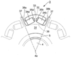
- FIG. 3 is a front view of one pole of the rotor 3 as viewed from the direction of the rotation center axis 4a.
- FIG. 3 in order to facilitate understanding of the configuration of the rotor 3, in addition to the configuration of one pole, the configuration of the pole on both sides in the rotational direction is shown by a broken line.
- the rotor 3 is composed of a core 31 near the rotation center axis 4a, two permanent magnets 34a and 34b provided for each pole, and rotor steels of the permanent magnets 34a and 34b outside the rotation center axis 4a.
- Center bridge 32 of each pole formed between the outer peripheral edge 33 of the pole and the magnet embedded holes 35a and 35b and connecting the core 31 and the outer peripheral edge 33, and the q-axis projection 37 provided between the poles And can be roughly divided.
- the outer peripheral edge portion 33 for one pole has a substantially arc-shaped cross-sectional shape, and is connected to the core portion 31 via the center bridge 32 at the center in the rotor rotation direction.
- the outer peripheral surface of the outer peripheral edge portion 33 has a curvature radius smaller than the distance from the rotation center axis 4 a to the rotor outermost peripheral portion.
- the radius of curvature of a part of the outer peripheral edge 33 may be smaller than the distance from the rotation center axis 4a to the outermost periphery of the rotor, instead of the entire outer peripheral edge 33 as described above.
- the outer peripheral surface of the outer peripheral edge portion 33 does not have to be a curved surface, and the outer peripheral surface of the outer peripheral edge portion 33 located on the extension passing through the center bridge 32 as viewed from the rotor rotation center The distance from the rotation center should be long.
- the torque of the permanent magnet embedded type rotating electrical machine can be increased by increasing the magnetic resistance of the center bridge 32 and decreasing the magnetic resistance of the stator and the outer peripheral edge portion 33 disposed on the outer periphery of the rotor. it can.
- the outer peripheral edge portion 33 By forming the outer peripheral edge portion 33 in such a shape, the harmonic component of the torque is reduced, and the fundamental wave component of the torque generated in the rotor 3 can be increased by the reduced amount.
- a magnet embedding hole 35a for holding the permanent magnet 34a and a magnet embedding hole 35b for holding the permanent magnet 34b are provided inside the outer peripheral edge portion 33.
- the magnet embedding holes 35 a and 35 b are surrounded in three directions by the outer peripheral edge portion 33, the center bridge 32 and the core portion 31.
- the outer peripheral edge portion 33 supports the permanent magnets 34 a and 35 b on the side of the central rotation axis 4 a against the centrifugal force acting on the permanent magnets 34 a and 34 b when the rotor 3 rotates.
- Each outer peripheral edge portion 33 corresponding to each pole is aligned in the rotor rotational direction with a gap between adjacent outer peripheral portions.
- the gap between the two outer peripheral portions 33 is located on the opposite side to the center bridge 32, that is, in the middle between the poles.
- the magnet embedding holes 35 a and 35 b are in communication with the outer periphery of the rotor via the gap between the two outer peripheral portions 33.
- Many commonly known conventional rotors do not have a gap between the two outer peripheral edges 33 and have side bridges connecting between the two outer peripheral edges 33. Where this side bridge is eliminated, one feature of the rotor 3 shown in FIGS. 2 and 3 is.
- Magnet embedding holes 35a and 35b are arranged in an inverted V-shape.
- the region (core 31) on the rotation center axis 4a side of the inner peripheral wall of the magnet embedding holes 35a and 35b is apart from the center between adjacent poles and between the two magnet embedding holes (that is, the center bridge 32) Is inclined in a direction away from the central axis 4a of rotation. For this reason, the center bridge 32 is located at a position radially outwardly of the inscribed circle 36 of all the magnet embedding holes 35 a and 35 b of the rotor 3.
- the q-axis projection 37 passes through the gap between the two outer peripheral edge portions 33 at a central position between the poles of the core portion 31 and protrudes in the centrifugal direction (the direction away from the rotation center axis 4a).
- the magnet embedding holes 35a and 35b are provided with positioning projections 38a and 38b for restricting the movement of the permanent magnets 34a and 34b to the q-axis projection 37 side.
- the positioning projections 38a and 38b are regions of the inner walls of the magnet embedding holes 35a and 35b which are radially outward of the rotor when viewed from the permanent magnets 34a and 34b, that is, the end on the q axis projection 37 side of the outer peripheral edge 33 And protrudes toward the rotation center axis 4a.
- the permanent magnets 34a and 34b are pressed against the positioning projections 38a and 38b and fixed in the magnet embedding holes 35a and 35b.
- a pair of end plates (not shown) is provided at both axial ends of the rotor 3 so that the permanent magnets 34 a and 34 b do not fall off in the axial direction.
- the above is the configuration of the rotor 3.
- the reason why the magnet embedding holes 35a and 35b are communicated with the outer periphery of the rotor 3 in the rotor 3 is as follows.
- an interference fit such as a shrink fit.
- tensile stress remains in the circumferential direction on the rotor steel material.
- This residual stress hardly occurs on the circumference of the rotor steel having the same radius as that of a portion such as a hole or a recess (that is, there is no hole or recess, and no stress remains unless it is a ring connected portion ).
- the configuration of the rotor a configuration in which the magnet embedded holes 35a and 35b communicate with the outer periphery of the rotor, that is, a configuration without the side bridge is adopted.
- this configuration since the rotor does not have the side bridge on the outermost periphery, no assembly residual stress remains on the outermost periphery of the rotor.
- the stress generated by the centrifugal force at the time of rotation of the rotor is concentrated on the center bridge, but the stress acting on this center bridge is a tensile stress, so that the center bridge is not damaged by adjusting the width of the center bridge. It is easy to do.
- the permanent magnet 34a or 34b is broken.
- the fragments of the permanent magnet may be discharged from the magnet embedding holes 35a and 35b to the outer periphery of the rotor, and in the worst case, the fragments may be caught and the rotor may not be able to rotate.
- seat for reinforcement adhered to the outer peripheral surface are inserted in the magnet embedding holes 35a and 35b.
- the reinforcing sheets of the permanent magnets 34a and 34b are not adhered to the inner walls of the magnet embedding holes 35a and 35b, and can slide relative to the inner walls It is. This point is the greatest feature of the present invention.
- FIG. 4 is a front view showing the configuration of the permanent magnet 341 and the reinforcing sheet 342 inserted into the magnet embedding holes 35a and 35b (see FIGS. 2 and 3) of the rotor 3 in the first embodiment of the present invention.
- FRP fiber reinforced resin
- the thickness of the reinforcing sheet 342 for one turn is about 80 ⁇ m.
- the reinforcing sheet 342 While the reinforcing sheet 342 is wound, the reinforcing sheet 342 and the permanent magnet 341 are heated, and the reinforcing sheet 342 is thermally cured to adhere to the surface of the permanent magnet 341.
- FRP what used epoxy as resin and used glass fiber as a fiber is applied.
- the epoxy can prevent the change of the magnetic properties of the permanent magnet during the thermal curing by using the epoxy of the curing condition that the curing temperature of the resin does not exceed the Curie temperature of the permanent magnet.
- the surface of the reinforcing sheet 342 is dried and the adhesive action is not generated. In this state, the permanent magnet 341 with the reinforcing sheet 342 attached is inserted into the magnet embedding holes 35a and 35b of the rotor 3 to magnetize the permanent magnet 341.
- the permanent magnet 341 to which the reinforcing sheet 342 is attached is inserted into the magnet embedding holes 35a and 35b of the rotor 3, the permanent magnet 341 can be made difficult to be broken at the time of insertion. Further, in the present embodiment, the surface of the reinforcing sheet 342 attached to the permanent magnet 341 is in a non-adhesive state with respect to the inner wall of the magnet embedding hole 35a or 35b and is slidable.
- the stress due to the difference in linear expansion coefficient between the rotor 3 and the permanent magnet 341 is prevented from being applied to the permanent magnet 341, It is possible to prevent the permanent magnet 341 from being broken. Further, in this configuration, even if the permanent magnet 341 breaks, it is difficult for the fragments to separate, and the permanent magnet 341 does not easily move in the magnet embedding hole 35a or 35b.
- FIG. 5 is a front view showing the configuration of the permanent magnet 341 and the reinforcing sheet 342 inserted into the magnet embedding holes 35a and 35b of the rotor 3 in the second embodiment of the present invention.
- the reinforcing sheet 342 is wound for five turns around four surfaces including the magnetized surfaces of the permanent magnet 341.
- three of the two magnetized surfaces and one non-magnetic surface are used.
- a reinforcing sheet 342 is wound on the surface for five turns. That is, in the present embodiment, the reinforcing sheet 342 is not attached to one non-magnetized surface among the four surfaces around the permanent magnet 341.
- the permanent magnet 341 when the permanent magnet 341 is embedded in the rotor 3, the permanent magnet 341 is embedded in the magnet embedded hole such that the non-magnetized surface on the permanent magnet 341 to which the reinforcing sheet 342 is not attached is on the center bridge 32 side. Insert into 35a or 35b. In this case, of the four surfaces around the permanent magnet 341, the non-magnetized surface covered by the reinforcing sheet 342 will come into the gap that connects the magnet embedding hole 35a or 35b to the outer periphery of the rotor 3. Therefore, it is possible to prevent the permanent magnet 341 from being broken at this non-magnetized surface, and to prevent fragments of the permanent magnet 341 from scattering toward the outer periphery of the rotor 3.
- the reinforcing sheet 342 is wound only on the three surfaces of the permanent magnet 341, the process of winding the reinforcing sheet 342 around the permanent magnet 341 is simplified compared to the first embodiment in which the reinforcing sheet 342 is wound. Can be done.
- FIG. 6 is a front view showing the configuration of the permanent magnet 341 and the reinforcing sheet 342 inserted into the magnet embedding holes 35a and 35b of the rotor 3 in the third embodiment of the present invention.
- the reinforcing sheet 341 for five turns is wound on the two magnetized surfaces and one non-magnetized surface of the permanent magnet 341, but in the present embodiment, the reinforcing sheet for one turn is reinforced.
- the sheet 341 is wound around two magnetized surfaces and one non-magnetized surface of the permanent magnet 341. Further, in the present embodiment, the end portion of the reinforcing sheet 341 slightly protrudes from the two magnetized surfaces of the permanent magnet 341, is bent, and adheres to the non-magnetized surface.
- the FRP used as the reinforcing sheet 341 has a high adhesive strength between the FRPs when multiple turns are wound, but has a low adhesive strength between the FRP and the permanent magnet 341. Therefore, in the present embodiment, for example, the FRP is bonded to the surface of the permanent magnet 341 by pressing the FRP against the surface of the permanent magnet 341 with a strong tightening force and thermally curing the adhesive strength of the FRP to the permanent magnet 341 To raise
- the permanent magnet 341 when the permanent magnet 341 is embedded in the rotor 3, the permanent magnet 341 is embedded in the permanent magnet 341 so that the non-magnetized surface to which the reinforcing sheet 342 is not attached is on the center bridge 32 side. Insert into holes 35a or 35b.
- the reinforcing sheet 342 sandwiched between the magnetized surface of the permanent magnet 341 and the inner wall surface of the magnet embedding hole 35a or 35b has a thickness of only one turn. Therefore, the magnetic flux density between the magnetized surface of the permanent magnet 341 and the inner wall surface of the magnet embedding hole 35a or 35b can be increased, and a large torque can be generated on the rotor 3 by the small-scale permanent magnet 341. Further, in the present embodiment, the end portion of the reinforcing sheet 341 slightly protrudes from the two magnetized surfaces of the permanent magnet 341, is bent, and adheres to the non-magnetized surface.
- the reinforcing sheet 342 covers the corner of the boundary between the magnetized surface of the permanent magnet 341 and the non-magnetized surface. Therefore, it is possible to prevent the permanent magnet 341 from being broken by preventing the corner of the boundary between the magnetized surface and the non-magnetized surface of the permanent magnet 341 from directly colliding with the inner wall of the magnet embedding hole 35a or 35b.
- FIG. 7 is a front view showing the configuration of the permanent magnet 341 and the reinforcing sheet 342 inserted into the magnet embedding holes 35a and 35b of the rotor 3 in the fourth embodiment of the present invention.
- the reinforcing sheet 341 for five turns is wound around four surfaces including the two magnetized surfaces of the permanent magnet 341 and thermally cured, the left surface is conformed to the shape of the inner wall of the magnet embedding hole 35a or 35b. Add chamfering to.
- the permanent magnet 341 when the permanent magnet 341 is embedded in the rotor 3, the permanent magnet 341 is set such that the non-magnetized surface to which the reinforcing sheet 342 chamfered in the permanent magnet 341 is attached is on the center bridge 32 side. It inserts in magnet embedding hole 35a or 35b.
- the chamfered and rounded reinforcing sheet 342 is the magnet embedding hole 35a. Or contact the inner wall of 35b.
- the contact portion with the inner wall of the magnet embedding hole 35a or 35b is likely to be painful.
- the left end portion of the reinforcing sheet 342 in FIG. 7 has a sufficiently large radius of curvature, so that the impact of contact with the inner wall of the magnet embedding hole 35a or 35b can be mitigated and breakage can be avoided. .
- removal processing for four turns is applied to the upper and lower two surfaces of the reinforcing sheet 342 in FIG. 7 to reinforce between the magnetized surface of the permanent magnet 341 and the inner wall of the magnet embedding hole 35a or 35b.
- the thickness of the sheet 342 is one turn. Therefore, as in the third embodiment, the magnetic flux density between the magnetized surface of the permanent magnet 341 and the inner wall surface of the magnet embedding hole 35a or 35b can be increased, and the small-scale permanent magnet 341 makes the rotor a large torque. 3 can be generated.
- FIG. 8 is a front view showing a configuration of permanent magnets 341, reinforcing sheets 342 and spacers 343 inserted into magnet embedded holes 35a and 35b of rotor 3 in the fifth embodiment of the present invention.
- the reinforcing sheet 342 having the same form as that of the fourth embodiment is attached to the permanent magnet 341, but nonmagnetic and nonconductive made of nylon or the like inside the first turn of the reinforcing sheet 342.
- Spacer 343 is provided.
- a reinforcing sheet 341 made of FRP is wound and thermally cured, and the FRP similar to the fourth embodiment is performed. Chamfering and removal process.
- the spacer 343 may be adhered and fixed to the permanent magnet 341 by an adhesive, or may be fixed to the permanent magnet 341 by a fixing tool such as a screw.
- the permanent magnet 341 when the permanent magnet 341 is embedded in the rotor 3, the permanent magnet 341 is placed in the magnet embedding hole 35 a or so that the non-magnetized surface on which the spacer 343 is fixed in the permanent magnet 341 is the center bridge 32 side. Insert in 35b.
- the reinforcing sheet 342 can be pressed against the inner wall of the magnet embedding hole 35a or 35b by the spacer 343. Accordingly, both the number of turns and the removal processing amount of the reinforcing sheet 342 can be reduced, which is economical.
- the thickness of the reinforcing sheet 342 between the magnetized surface of the permanent magnet 341 and the inner wall of the magnet embedding hole 35a or 35b is one turn. Therefore, the magnetic flux density between the magnetized surface of the permanent magnet 341 and the inner wall surface of the magnet embedding hole 35a or 35b can be increased, and a large torque can be generated on the rotor 3 by the small-scale permanent magnet 341.
- FIG. 9 is a front view showing a configuration of permanent magnets 341, reinforcing sheets 342 and spacers 343 inserted into magnet embedding holes 35a and 35b of rotor 3 in the sixth embodiment of the present invention.
- the configuration of the permanent magnet 341 and the reinforcing sheet 342 is the same as that of the third embodiment (FIG. 6).
- a spacer 343 made of nylon or the like is fixed to the non-magnetized surface of the permanent magnet 341 to which the reinforcing sheet 342 is not attached.
- the spacer 343 may be fixed to the permanent magnet 341 by an adhesive, or may be fixed to the permanent magnet 341 by a fixing tool such as a screw. Further, as a material of the spacer 343, FRP laminated in advance may be used.
- the permanent magnet 341 when the permanent magnet 341 is embedded in the rotor 3, the permanent magnet 341 is placed in the magnet embedding hole 35 a or so that the non-magnetized surface on which the spacer 343 is fixed in the permanent magnet 341 is the center bridge 32 side. Insert in 35b. Also in this embodiment, the same effect as that of the fifth embodiment can be obtained.
- FIG. 10 shows a part of the manufacturing process of the permanent magnet embedded-type electric rotating machine according to the seventh embodiment of the present invention.
- the present embodiment relates to the process of fixing the reinforcing sheet 342 made of FRP to the permanent magnet 341, among the processes of the manufacturing process of the permanent magnet embedded type rotary electric machine.
- the reinforcing sheet 342 is fixed to four surfaces of the permanent magnet 341 as in, for example, the first embodiment (FIG. 4), the fourth embodiment (FIG. 7), and the fifth embodiment (FIG. 8). Suitable for
- the end of the reinforcing sheet 342 is formed on one surface around the permanent magnet 341 (the non-magnetized surface on the left side in the example shown in FIG. 10A). In the state where the part is fixed, this end is locally heated and thermally cured, and fixed to the permanent magnet 341.
- the reinforcing sheet 342 is wound around the permanent magnet 341 while applying tension to the reinforcing sheet 342.
- the reinforcing sheet 342 is wound around the permanent magnet 341 by the required number of turns, as shown in FIG.
- a part of the reinforcing sheet 342 is locally heated and thermally cured, and the part is It is bonded to the reinforcing sheet 342 of the inner turn. Then, the surplus reinforcing sheet 342 after this bonding point is separated. In this manner, a reinforcing sheet 342 having the necessary number of turns is wound and fixed around the permanent magnet 341.
- the reinforcing sheet 342 having the necessary number of turns is wound and fixed around the permanent magnet 341 and placed in a furnace and heated, and the entire reinforcing sheet 342 wound around the permanent magnet 341 is thermally cured. It is fixed around the
- the adhesive strength of the reinforcing sheet 342 to the permanent magnet 341, and the reinforcing sheet 342 for each turn are provided.
- the adhesive strength between them can be increased.
- FIG. 11 shows a part of the manufacturing process of the permanent magnet embedded-type electric rotating machine according to the eighth embodiment of the present invention. Similar to the seventh embodiment, the present embodiment relates to the step of fixing the reinforcing sheet 342 made of FRP to the permanent magnet 341. This embodiment is suitable, for example, for fixing the reinforcing sheet 342 to the permanent magnet 341 as in the second embodiment (FIG. 5), the third embodiment (FIG. 6) and the sixth embodiment (FIG. 9). It is.
- the reinforcing sheet 342 having a desired number of turns is a desired surface (perpendicularly in the example shown in FIG. In the state of contact with the surface), the reinforcing sheet 342 is pressed against the permanent magnet 341, and in this state, the reinforcing sheet 342 and the permanent magnet 341 are heated to thermally cure the reinforcing sheet 342.
- the adhesive strength of the reinforcing sheet 342 for the permanent magnet 341 and the space between the reinforcing sheets 342 for each turn are obtained.
- the bonding strength in the case of fixing the plurality of turns of the reinforcing sheet 342 to the permanent magnet 341) can be increased.
- the reinforcing sheet 342 is attached to the permanent magnet 341 and embedded in the magnet embedding hole 35a or 35b, the permanent magnet 341 can be made hard to break. Also, even if the permanent magnet 341 breaks, separation of the magnet and the fragments can be prevented. Further, according to each embodiment of the present invention, the surface of the reinforcing sheet 342 attached to the permanent magnet 341 and the inner wall of the magnet embedded hole 35a or 35b are not adhered in the state embedded in the magnet embedded hole 35a or 35b. It has become.
- the stress caused by the difference between the linear expansion coefficients of the permanent magnet 341 and the rotor 3 is prevented from being applied to the permanent magnet 341 due to the temperature rise of the rotor 3. Can be prevented.
- the surface of the reinforcing sheet 342 and the inner wall of the magnet embedding hole 35a or 35b are in a non-bonded state, but the thermal stress caused by the difference in linear expansion coefficient between the rotor 3 and the permanent magnet 341 It may be in an elastic adhesive state. Therefore, according to each embodiment of the present invention, it is possible to realize a permanent magnet embedded type rotary electric machine which can stably use a permanent magnet which originally has a characteristic of being easily broken over a long period of time.
- the reinforcing sheet 342 is thermally cured and attached to the material of the permanent magnet 341, the material is magnetized, so that demagnetization due to the high temperature at the time of thermal curing of the reinforcing sheet 342 is eliminated. Further, according to each embodiment of the present invention, it is possible to provide such a permanent magnet embedded type rotary electric machine which is small in size, low in cost and easy in maintenance.
- the reinforcing sheet 342 is wound around three or four sides of the permanent magnet 341, but may be wound around one, two or five or more sides of the permanent magnet 341.
- the shape of the permanent magnet 341 is a roughly hexahedron, but permanent magnets of other shapes may be used.
- thermosetting reinforcing sheet 342 made of FRP is used, but a reinforcing sheet made of another material may be used.
- the permanent magnet 341 is accommodated in a tube-like reinforcing sheet 342 made of a heat-shrinkable material, and the reinforcing sheet 342 is heated and shrunk, FIG. 12 (b) It may be fixed around the permanent magnet 341 as shown in FIG.
- the present invention is applied to a rotor without side bridges, but the present invention may be applied to a rotor with side bridges.
- the reinforcing sheet 342 is thermally cured and attached to the material of the magnet, the material is magnetized to form the permanent magnet 341.
- the reinforcing sheet 342 may be attached.
Abstract
Description
図1は本発明の適用対象である永久磁石埋め込み式回転電機の構成例を示す縦断面図である。図1において、フレーム1は、永久磁石埋め込み式回転電機全体を覆う筐体であり、鉄、アルミ、ステンレスなどにより構成されている。フレーム1の内側には、中空円筒状の固定側鉄心2が設けられている。この固定側鉄心2は、けい素鋼板を積層してなるものである。この固定側鉄心2には、複数のティースが形成されており、各ティースには銅線などによるステータ巻線が巻装されている(図示略)。固定側鉄心2の内側には、固定側鉄心2との間に所定の隙間を挟んだ状態で、回転側鉄心であるロータ3が挿通されている。このロータ3は、けい素鋼板を積層してなるものである。なお、単純な鉄ブロックを切削加工することによりロータ3が構成される場合もある。ロータ3は、その中心を鉄などによるシャフト4が貫通している。理想的には、シャフト4の中心軸がロータ3の回転中心軸4aとなる。そして、シャフト4は、ベアリング鋼などからなる転がり軸受け5を介して、フレーム1の前後両端に設けられたシールド6に支持されている。 <Application target of the present invention>
FIG. 1 is a longitudinal sectional view showing a configuration example of a permanent magnet embedded type rotary electric machine to which the present invention is applied. In FIG. 1, a
以上がロータ3の構成である。 The q-
The above is the configuration of the
図4はこの発明の第1実施形態においてロータ3の磁石埋め込み穴35aおよび35b(図2、図3参照)に挿入される永久磁石341および補強用シート342の構成を示す正面図である。この例では、永久磁石341の着磁面(永久磁石のN極またはS極がある面)を含む4面に、補強用シート342としてFRP(繊維強化樹脂)が5ターン巻かれている。ここで、1ターン分の補強用シート342の厚さは80μm程度である。この補強用シート342を巻き付けた状態で補強用シート342および永久磁石341を加熱し、補強用シート342を熱硬化させて永久磁石341の表面に付着させる。FRPとしては樹脂としてエポキシを、繊維としてガラス繊維を用いたものを適用する。このエポキシは、樹脂の硬化温度が永久磁石のキュリー温度を越えない硬化条件のものを用いることにより、熱硬化の際に永久磁石の磁気特性が変化するのを防止することができる。熱硬化後、温度が下がると、補強用シート342の表面は乾燥し、接着作用を生じない状態となる。この状態において、補強用シート342の付着した永久磁石341をロータ3の磁石埋め込み穴35aおよび35bに挿入し、永久磁石341の着磁を行う。 First Embodiment
FIG. 4 is a front view showing the configuration of the
図5はこの発明の第2実施形態においてロータ3の磁石埋め込み穴35aおよび35bに挿入される永久磁石341および補強用シート342の構成を示す正面図である。上記第1実施形態では、永久磁石341の着磁面を含む4面に補強用シート342を5ターン分巻いたが、本実施形態では2つの着磁面と1つの非着磁面からなる3面に補強用シート342を5ターン分巻いている。すなわち、本実施形態では、永久磁石341の周囲の4面のうち1つの非着磁面には、補強用シート342が付着していない。 Second Embodiment
FIG. 5 is a front view showing the configuration of the
図6はこの発明の第3実施形態においてロータ3の磁石埋め込み穴35aおよび35bに挿入される永久磁石341および補強用シート342の構成を示す正面図である。上記第2実施形態(図5)では、5ターン分の補強用シート341を永久磁石341の2つの着磁面および1つの非着磁面に巻いたが、本実施形態では1ターン分の補強用シート341を永久磁石341の2つの着磁面および1つの非着磁面に巻いている。また、本実施形態において、補強用シート341の端部は永久磁石341の2つの着磁面から僅かにはみ出して折れ曲がり、非着磁面に付着している。 Third Embodiment
FIG. 6 is a front view showing the configuration of the
図7はこの発明の第4実施形態においてロータ3の磁石埋め込み穴35aおよび35bに挿入される永久磁石341および補強用シート342の構成を示す正面図である。本実施形態では、5ターン分の補強用シート341を永久磁石341の2つの着磁面を含む4面に巻いて熱硬化させた後、磁石埋め込み穴35aまたは35bの内壁の形状に合わせて左面に面取り加工を加える。 Fourth Embodiment
FIG. 7 is a front view showing the configuration of the
図8はこの発明の第5実施形態においてロータ3の磁石埋め込み穴35aおよび35bに挿入される永久磁石341、補強用シート342およびスペーサ343の構成を示す正面図である。本実施形態では、上記第4実施形態と同様な形態の補強用シート342を永久磁石341に付着させるが、この補強用シート342の1ターン目の内側にナイロン等からなる非磁性かつ非導電性のスペーサ343を設けている。具体的には、本実施形態では、予め永久磁石341の左面にナイロンのスペーサ343を接着固定した後、FRPからなる補強用シート341を巻いて熱硬化させ、上記第4実施形態と同様なFRPの面取りおよび除去処理を行っている。スペーサ343は、接着剤により永久磁石341に接着固定する他、ネジ等の固定具に永久磁石341に固定してもよい。 Fifth Embodiment
FIG. 8 is a front view showing a configuration of
図9はこの発明の第6実施形態においてロータ3の磁石埋め込み穴35aおよび35bに挿入される永久磁石341、補強用シート342およびスペーサ343の構成を示す正面図である。 Sixth Embodiment
FIG. 9 is a front view showing a configuration of
図10はこの発明の第7実施形態である永久磁石埋め込み式回転電機の製造工程の一部を示すものである。本実施形態は、永久磁石埋め込み式回転電機の製造工程の各工程のうち、特にFRPからなる補強用シート342を永久磁石341に固定する工程に関するものである。本実施形態は、例えば上記第1実施形態(図4)、第4実施形態(図7)、第5実施形態(図8)のように補強用シート342を永久磁石341の4面に固定するのに好適である。 Seventh Embodiment
FIG. 10 shows a part of the manufacturing process of the permanent magnet embedded-type electric rotating machine according to the seventh embodiment of the present invention. The present embodiment relates to the process of fixing the reinforcing
図11はこの発明の第8実施形態である永久磁石埋め込み式回転電機の製造工程の一部を示すものである。上記第7実施形態と同様、本実施形態は、FRPからなる補強用シート342を永久磁石341に固定する工程に関するものである。本実施形態は、例えば上記第2実施形態(図5)、第3実施形態(図6)、第6実施形態(図9)のように補強用シート342を永久磁石341に固定するのに好適である。 Eighth Embodiment
FIG. 11 shows a part of the manufacturing process of the permanent magnet embedded-type electric rotating machine according to the eighth embodiment of the present invention. Similar to the seventh embodiment, the present embodiment relates to the step of fixing the reinforcing
以上、この発明の各実施形態について説明したが、この発明には他にも実施形態が考えられる。例えば次の通りである。 Other Embodiments
As mentioned above, although each embodiment of this invention was described, other embodiments can be considered to this invention. For example:
Claims (20)
- ロータに周方向に沿って形成された磁石埋め込み穴に補強用シートの付着した永久磁石を埋め込んでなり、前記補強用シートの表面が前記磁石埋め込み穴の内壁面に対して非接着状態であることを特徴とする永久磁石埋め込み式回転電機。 A permanent magnet to which a reinforcing sheet is attached is embedded in a magnet embedding hole formed along a circumferential direction in a rotor, and the surface of the reinforcing sheet is not adhered to the inner wall surface of the magnet embedding hole. Permanent magnet embedded type rotary electric machine characterized by
- 前記補強用シートは、繊維強化樹脂のシートを熱硬化させたものであり、熱硬化により前記繊維強化樹脂のシートが表面に付着した永久磁石を前記磁石埋め込み穴に埋め込んでなることを特徴とする請求項1に記載の永久磁石埋め込み式回転電機。 The reinforcing sheet is obtained by thermally curing a sheet of fiber reinforced resin, and a permanent magnet having the sheet of the fiber reinforced resin adhered to the surface by thermal curing is embedded in the magnet embedding hole. The permanent magnet embedded-type electric rotating machine according to claim 1.
- 前記繊維強化樹脂における樹脂の硬化温度を前記永久磁石のキュリー温度を越えない温度としたことを特徴とする請求項2に記載の永久磁石埋め込み式回転電機。 The permanent magnet embedded-type electric rotating machine according to claim 2, wherein a curing temperature of the resin in the fiber reinforced resin is a temperature not exceeding the Curie temperature of the permanent magnet.
- 前記補強用シートの一部に除去加工を加えてなることを特徴とする請求項1に記載の永久磁石埋め込み式回転電機。 The permanent magnet embedded-type electric rotating machine according to claim 1, wherein a removal process is applied to a part of the reinforcing sheet.
- 前記補強用シートを前記永久磁石に巻き付けてなることを特徴とする請求項1に記載の永久磁石埋め込み式回転電機。 The permanent magnet embedded-type electric rotating machine according to claim 1, wherein the reinforcing sheet is wound around the permanent magnet.
- 前記補強用シートは、繊維強化樹脂のシートを熱硬化させたものであり、熱硬化により前記繊維強化樹脂のシートが表面に付着した永久磁石を前記磁石埋め込み穴に埋め込んでなることを特徴とする請求項5に記載の永久磁石埋め込み式回転電機。 The reinforcing sheet is obtained by thermally curing a sheet of fiber reinforced resin, and a permanent magnet having the sheet of the fiber reinforced resin adhered to the surface by thermal curing is embedded in the magnet embedding hole. The permanent magnet embedded-type electric rotating machine according to claim 5.
- 前記補強用シートの巻き付けターン数を複数ターンとしたことを特徴とする請求項5に記載の永久磁石埋め込み式回転電機。 The permanent magnet embedded-type electric rotating machine according to claim 5, wherein the number of winding turns of the reinforcing sheet is a plurality of turns.
- 前記補強用シートの一部に除去加工を加えてなることを特徴とする請求項5に記載の永久磁石埋め込み式回転電機。 The permanent magnet embedded-type electric rotating machine according to claim 5, characterized in that removal processing is added to a part of the reinforcing sheet.
- 前記補強用シートの巻き付けターン数を複数ターンとし、前記補強用シートの一部に除去加工を加え、1ターン分以上の前記補強用シートを除去加工を加えずに残したことを特徴とする請求項5に記載の永久磁石埋め込み式回転電機。 The number of winding turns of the reinforcing sheet is a plurality of turns, a part of the reinforcing sheet is removed, and one or more turns of the reinforcing sheet are left without being removed. The permanent magnet embedded-type electric rotating machine according to Item 5.
- 前記永久磁石の着磁方向に垂直な着磁面に付着した前記補強用シートを多く削り、前記着磁面以外の非着磁面に付着した前記補強用シートを多く残したことを特徴とする請求項8に記載の永久磁石埋め込み式回転電機。 A large number of the reinforcing sheets attached to the magnetized surface perpendicular to the magnetization direction of the permanent magnet are cut, and a large number of the reinforcing sheets attached to the non-magnetized surface other than the magnetized surface are left. The permanent magnet embedded-type electric rotating machine according to claim 8.
- 前記永久磁石の着磁方向に垂直な着磁面に付着した前記補強用シートを多く削り、前記着磁面以外の非着磁面に付着した前記補強用シートを多く残したことを特徴とする請求項9に記載の永久磁石埋め込み式回転電機。 A large number of the reinforcing sheets attached to the magnetized surface perpendicular to the magnetization direction of the permanent magnet are cut, and a large number of the reinforcing sheets attached to the non-magnetized surface other than the magnetized surface are left. The permanent magnet embedded-type electric rotating machine according to claim 9.
- 前記永久磁石に非磁性かつ非導電体のスペーサを付加し、前記永久磁石および前記スペーサに前記補強用シートを巻き付けてなることを特徴とする請求項1に記載の永久磁石埋め込み式回転電機。 2. A permanent magnet embedded rotary electric machine according to claim 1, wherein a nonmagnetic and nonconductive spacer is added to the permanent magnet, and the reinforcing sheet is wound around the permanent magnet and the spacer.
- 前記スペーサを接着またはネジ等の固定具により前記永久磁石に固定し、前記補強用シートを巻き付けてなることを特徴とする請求項12に記載の永久磁石埋め込み式回転電機。 The permanent magnet embedded-type electric rotating machine according to claim 12, wherein the spacer is fixed to the permanent magnet by a bonding tool such as bonding or a screw, and the reinforcing sheet is wound.
- 前記補強用シートの付着した永久磁石に非磁性かつ非導電体のスペーサを付加してなることを特徴とする請求項1に記載の永久磁石埋め込み式回転電機。 2. A permanent magnet embedded type rotary electric machine according to claim 1, wherein a nonmagnetic and nonconductive spacer is added to the permanent magnet to which the reinforcing sheet is attached.
- 前記ロータは前記磁石埋め込み穴の間にセンタブリッジが形成され、前記磁石埋め込み穴は前記センタブリッジと反対側において前記ロータの外周に連通し、前記センタブリッジは前記磁石埋め込み穴の内接円よりも前記ロータの半径方向外側に位置していることを特徴とする請求項1~14のいずれか1の請求項に記載の永久磁石埋め込み式回転電機。 The rotor has a center bridge formed between the magnet embedding holes, and the magnet embedding holes communicate with the outer periphery of the rotor on the side opposite to the center bridge, and the center bridge is smaller than the inscribed circle of the magnet embedding holes. The permanent magnet embedded type rotary electric machine according to any one of claims 1 to 14, which is located radially outward of the rotor.
- 前記ロータは隣接するセンタブリッジの間に、ロータ回転中心軸から離れる方向に突出したq軸突起を有することを特徴とする請求項1~14のいずれか1の請求項に記載の永久磁石埋め込み式回転電機。 The permanent magnet embedded type according to any one of claims 1 to 14, wherein the rotor has a q-axis projection projecting in a direction away from the central axis of rotation of the rotor between adjacent center bridges. Electric rotating machine.
- ロータに形成された磁石埋め込み穴に補強用シートの付着した永久磁石を埋め込んでなる永久磁石埋め込み式回転電機の製造方法において、
前記補強用シートとして、熱硬化性の繊維強化樹脂のシートを用い、前記繊維強化樹脂のシートを接触させて熱硬化させることにより補強用シートの付着した永久磁石を製造し、熱硬化した補強用シートの付着した永久磁石を前記ロータに形成された磁石埋め込み穴に挿入することを特徴とする永久磁石埋め込み式回転電機の製造方法。 In a method of manufacturing a permanent magnet embedded type rotary electric machine, wherein a permanent magnet to which a reinforcing sheet is attached is embedded in a magnet embedded hole formed in a rotor,
A sheet of a thermosetting fiber reinforced resin is used as the reinforcing sheet, and the sheet of the fiber reinforced resin is brought into contact and thermally cured to manufacture a permanent magnet to which the reinforcing sheet adheres, and which is thermally cured. A method of manufacturing a permanent magnet embedded-type electric rotating machine, comprising: inserting a permanent magnet attached with a sheet into a magnet embedded hole formed in the rotor. - 前記永久磁石の表面に熱硬化性の繊維強化樹脂のシートの一部を接触させ、かつ、加熱することにより当該一部を熱硬化させて前記永久磁石の表面に固定し、前記繊維強化樹脂のシートを前記永久磁石の周囲に巻き付け、繊維強化樹脂のシートの他の一部を接触させ、かつ、加熱することにより当該他の一部を熱硬化させて前記永久磁石の表面に固定することにより前記繊維強化樹脂のシートの巻き付けられた永久磁石を製造し、前記繊維強化樹脂のシートの巻き付けられた永久磁石を加熱することにより前記繊維強化樹脂のシートを熱硬化させて前記永久磁石の表面に付着させ、前記補強用シートの付着した永久磁石を製造することを特徴とする請求項17に記載の永久磁石埋め込み式回転電機の製造方法。 A part of a sheet of thermosetting fiber reinforced resin is brought into contact with the surface of the permanent magnet, and the part is thermally cured by heating to fix it on the surface of the permanent magnet; A sheet is wound around the permanent magnet, the other part of the sheet of fiber reinforced resin is brought into contact, and the other part is thermally cured by heating to fix it to the surface of the permanent magnet. The wound permanent magnet of the sheet of the fiber reinforced resin is manufactured, and the sheet of the fiber reinforced resin is thermally cured by heating the wound permanent magnet of the sheet of the fiber reinforced resin to form the surface of the permanent magnet. The method of manufacturing a permanent magnet embedded-type electric rotating machine according to claim 17, wherein the permanent magnet to which the reinforcing sheet is attached is manufactured to be adhered.
- 熱硬化性の繊維強化樹脂のシートを表面に押し当てつつ加熱することにより前記繊維強化樹脂のシートを熱硬化させて前記永久磁石の表面に付着させ、前記補強用シートの付着した永久磁石を製造することを特徴とする請求項17に記載の永久磁石埋め込み式回転電機の製造方法。 A sheet of thermosetting fiber reinforced resin is pressed against the surface and heated to thermally cure the sheet of fiber reinforced resin to adhere to the surface of the permanent magnet, thereby producing a permanent magnet with the reinforcing sheet attached. The method of manufacturing a permanent magnet embedded-type electric rotating machine according to claim 17, characterized in that:
- 前記補強用シートの付着後に前記永久磁石の着磁を行うことを特徴とする請求項17~19のいずれか1の請求項に記載の永久磁石埋め込み式回転電機の製造方法。 The method for manufacturing a permanent magnet embedded type rotary electric machine according to any one of claims 17 to 19, wherein the permanent magnet is magnetized after the adhesion of the reinforcing sheet.
Priority Applications (4)
| Application Number | Priority Date | Filing Date | Title |
|---|---|---|---|
| EP14851171.0A EP3054563B1 (en) | 2013-10-02 | 2014-09-11 | Permanent magnet embedded-type rotating electric machine and manufacturing method thereof |
| JP2015540443A JP6135770B2 (en) | 2013-10-02 | 2014-09-11 | Permanent magnet embedded rotary electric machine and method for manufacturing the same |
| CN201480027176.4A CN105210268B (en) | 2013-10-02 | 2014-09-11 | Permanent magnet submerged formula rotating electric machine and its manufacturing method |
| US14/941,518 US10263482B2 (en) | 2013-10-02 | 2015-11-13 | Permanent magnet embedded-type rotating electric machine and manufacturing method thereof |
Applications Claiming Priority (2)
| Application Number | Priority Date | Filing Date | Title |
|---|---|---|---|
| JP2013-207149 | 2013-10-02 | ||
| JP2013207149 | 2013-10-02 |
Related Child Applications (1)
| Application Number | Title | Priority Date | Filing Date |
|---|---|---|---|
| US14/941,518 Continuation US10263482B2 (en) | 2013-10-02 | 2015-11-13 | Permanent magnet embedded-type rotating electric machine and manufacturing method thereof |
Publications (1)
| Publication Number | Publication Date |
|---|---|
| WO2015049967A1 true WO2015049967A1 (en) | 2015-04-09 |
Family
ID=52778563
Family Applications (1)
| Application Number | Title | Priority Date | Filing Date |
|---|---|---|---|
| PCT/JP2014/074141 WO2015049967A1 (en) | 2013-10-02 | 2014-09-11 | Permanent magnet embedded rotating electric machine and method for manufacturing same |
Country Status (5)
| Country | Link |
|---|---|
| US (1) | US10263482B2 (en) |
| EP (1) | EP3054563B1 (en) |
| JP (1) | JP6135770B2 (en) |
| CN (1) | CN105210268B (en) |
| WO (1) | WO2015049967A1 (en) |
Cited By (2)
| Publication number | Priority date | Publication date | Assignee | Title |
|---|---|---|---|---|
| JP2017079502A (en) * | 2015-10-19 | 2017-04-27 | Tdk株式会社 | Magnet structure and motor using the same |
| JP2020145923A (en) * | 2020-05-15 | 2020-09-10 | Tdk株式会社 | Magnet structure and motor using the same |
Families Citing this family (3)
| Publication number | Priority date | Publication date | Assignee | Title |
|---|---|---|---|---|
| WO2014122947A1 (en) | 2013-02-08 | 2014-08-14 | 富士電機株式会社 | Permanent-magnet-embedded-type rotary electric machine |
| JP7338152B2 (en) * | 2018-12-12 | 2023-09-05 | 株式会社デンソー | Rotating electric machine |
| EP3910766A4 (en) * | 2019-01-11 | 2022-10-12 | NHK Spring Co., Ltd. | Method for manufacturing rotor, and rotor |
Citations (7)
| Publication number | Priority date | Publication date | Assignee | Title |
|---|---|---|---|---|
| JPH0919093A (en) * | 1995-06-28 | 1997-01-17 | Meidensha Corp | Permanent magnet of rotor |
| JPH09163649A (en) | 1995-12-07 | 1997-06-20 | Matsushita Electric Ind Co Ltd | Permanent magnet fixing method in permanent magnet embedding type motor |
| JP2001086671A (en) * | 1999-09-13 | 2001-03-30 | Sumitomo Special Metals Co Ltd | Magnet for motor, and its fixation method, and motor |
| JP2002359942A (en) * | 2001-05-31 | 2002-12-13 | Meidensha Corp | Structure of rotor of permanent magnet type dynamo- electric machine |
| JP2004007937A (en) * | 2002-04-16 | 2004-01-08 | Sumitomo Special Metals Co Ltd | Rotor and rotary machine |
| JP2007089383A (en) * | 2005-08-26 | 2007-04-05 | Denso Corp | Rotor of rotary electric machine |
| JP2013046421A (en) * | 2011-08-21 | 2013-03-04 | Toyota Industries Corp | Permanent magnet embedded electric motor |
Family Cites Families (10)
| Publication number | Priority date | Publication date | Assignee | Title |
|---|---|---|---|---|
| JP2002209439A (en) | 2001-01-18 | 2002-07-30 | Iseki & Co Ltd | Grafting robot |
| WO2006008964A1 (en) * | 2004-07-16 | 2006-01-26 | Mitsuba Corporation | Magnet fixing structure for electric rotating machine |
| JP4396471B2 (en) * | 2004-10-01 | 2010-01-13 | 株式会社デンソー | Rotating electric machine for vehicle and manufacturing method thereof |
| DE112007000139T5 (en) * | 2006-01-10 | 2008-11-13 | Mitsuba Corp., Kiryu-shi | Rotating electrical machine |
| JP5157138B2 (en) * | 2006-11-24 | 2013-03-06 | 株式会社日立製作所 | Permanent magnet rotating electrical machine and wind power generation system |
| JP5219589B2 (en) * | 2008-04-01 | 2013-06-26 | 三菱電機株式会社 | Rotating electric machine |
| JP5447418B2 (en) | 2011-03-28 | 2014-03-19 | 株式会社豊田自動織機 | Rotating electric machine permanent magnet embedded rotor and rotating electric machine |
| EP2742207A4 (en) | 2011-08-12 | 2016-06-29 | Mcalister Technologies Llc | Systems and methods for extracting and processing gases from submerged sources |
| US20130099617A1 (en) * | 2011-10-24 | 2013-04-25 | Bradley D. Chamberlin | Electric machine with magnet holder |
| JP5659172B2 (en) * | 2012-02-27 | 2015-01-28 | 株式会社日立製作所 | Permanent magnet rotating electric machine |
-
2014
- 2014-09-11 EP EP14851171.0A patent/EP3054563B1/en active Active
- 2014-09-11 WO PCT/JP2014/074141 patent/WO2015049967A1/en active Application Filing
- 2014-09-11 JP JP2015540443A patent/JP6135770B2/en active Active
- 2014-09-11 CN CN201480027176.4A patent/CN105210268B/en active Active
-
2015
- 2015-11-13 US US14/941,518 patent/US10263482B2/en active Active
Patent Citations (7)
| Publication number | Priority date | Publication date | Assignee | Title |
|---|---|---|---|---|
| JPH0919093A (en) * | 1995-06-28 | 1997-01-17 | Meidensha Corp | Permanent magnet of rotor |
| JPH09163649A (en) | 1995-12-07 | 1997-06-20 | Matsushita Electric Ind Co Ltd | Permanent magnet fixing method in permanent magnet embedding type motor |
| JP2001086671A (en) * | 1999-09-13 | 2001-03-30 | Sumitomo Special Metals Co Ltd | Magnet for motor, and its fixation method, and motor |
| JP2002359942A (en) * | 2001-05-31 | 2002-12-13 | Meidensha Corp | Structure of rotor of permanent magnet type dynamo- electric machine |
| JP2004007937A (en) * | 2002-04-16 | 2004-01-08 | Sumitomo Special Metals Co Ltd | Rotor and rotary machine |
| JP2007089383A (en) * | 2005-08-26 | 2007-04-05 | Denso Corp | Rotor of rotary electric machine |
| JP2013046421A (en) * | 2011-08-21 | 2013-03-04 | Toyota Industries Corp | Permanent magnet embedded electric motor |
Cited By (3)
| Publication number | Priority date | Publication date | Assignee | Title |
|---|---|---|---|---|
| JP2017079502A (en) * | 2015-10-19 | 2017-04-27 | Tdk株式会社 | Magnet structure and motor using the same |
| JP2020145923A (en) * | 2020-05-15 | 2020-09-10 | Tdk株式会社 | Magnet structure and motor using the same |
| JP6992841B2 (en) | 2020-05-15 | 2022-01-13 | Tdk株式会社 | Magnet structure and motor using it |
Also Published As
| Publication number | Publication date |
|---|---|
| JPWO2015049967A1 (en) | 2017-03-09 |
| EP3054563A4 (en) | 2017-06-21 |
| US10263482B2 (en) | 2019-04-16 |
| EP3054563B1 (en) | 2019-12-25 |
| CN105210268A (en) | 2015-12-30 |
| JP6135770B2 (en) | 2017-05-31 |
| EP3054563A1 (en) | 2016-08-10 |
| US20160072348A1 (en) | 2016-03-10 |
| CN105210268B (en) | 2019-03-26 |
Similar Documents
| Publication | Publication Date | Title |
|---|---|---|
| JP4815967B2 (en) | Permanent magnet rotating electric machine | |
| US7372181B2 (en) | Rotor for brushless motor and brushless motor | |
| JP6273499B2 (en) | Permanent magnet embedded motor and method for manufacturing the same | |
| CN110663159B (en) | Rotor, rotating electric machine, and method for manufacturing rotor | |
| JP5398512B2 (en) | Axial gap type permanent magnet motor, rotor used therefor, and method for manufacturing the rotor | |
| JP5486036B2 (en) | Electric motor having a rotor structure for preventing problems due to distortion caused by temperature change and method for manufacturing the same | |
| WO2015049967A1 (en) | Permanent magnet embedded rotating electric machine and method for manufacturing same | |
| KR102643516B1 (en) | Laminated core and rotating electric machines | |
| KR102607589B1 (en) | Laminated core and rotating electrical machines | |
| JPH06311677A (en) | Rotor assembly | |
| US20170012481A1 (en) | Reluctance rotor lamination having an opening for stress reduction | |
| JP2001025192A (en) | Permanent magnet type dynamo-electric machine and method of manufacturing the same | |
| JPH02223342A (en) | Rotor with permanent magnet and its manufacture | |
| JP6112970B2 (en) | Permanent magnet rotating electric machine | |
| JP2002191144A (en) | Permanent magnet rotor and manufacturing method for the rotor | |
| JP2018530303A (en) | Permanent magnet type rotor and manufacturing method thereof | |
| WO2011061806A1 (en) | Method of manufacturing rotor of electric motor | |
| JP2009239988A (en) | Permanent magnet type motor | |
| JP5648438B2 (en) | Rotor core, rotor for rotating electrical machine, and method for manufacturing rotor core for rotating electrical machine | |
| KR20140143356A (en) | Rotor including segmented yoke | |
| JP2001025191A (en) | Rotor of motor and manufacture thereof | |
| JP2007074899A (en) | Rotor of motor-driven blower | |
| JP6876692B2 (en) | Rotating machine | |
| JP6685166B2 (en) | Axial gap type rotating electric machine | |
| JP5962055B2 (en) | Field pole magnet body |
Legal Events
| Date | Code | Title | Description |
|---|---|---|---|
| 121 | Ep: the epo has been informed by wipo that ep was designated in this application |
Ref document number: 14851171 Country of ref document: EP Kind code of ref document: A1 |
|
| REEP | Request for entry into the european phase |
Ref document number: 2014851171 Country of ref document: EP |
|
| WWE | Wipo information: entry into national phase |
Ref document number: 2014851171 Country of ref document: EP |
|
| ENP | Entry into the national phase |
Ref document number: 2015540443 Country of ref document: JP Kind code of ref document: A |
|
| NENP | Non-entry into the national phase |
Ref country code: DE |