WO2015049895A1 - 継手及び航空機構造 - Google Patents
継手及び航空機構造 Download PDFInfo
- Publication number
- WO2015049895A1 WO2015049895A1 PCT/JP2014/063384 JP2014063384W WO2015049895A1 WO 2015049895 A1 WO2015049895 A1 WO 2015049895A1 JP 2014063384 W JP2014063384 W JP 2014063384W WO 2015049895 A1 WO2015049895 A1 WO 2015049895A1
- Authority
- WO
- WIPO (PCT)
- Prior art keywords
- joint
- groove
- fitting shape
- fitting
- shape
- Prior art date
- Legal status (The legal status is an assumption and is not a legal conclusion. Google has not performed a legal analysis and makes no representation as to the accuracy of the status listed.)
- Ceased
Links
Images


Classifications
-
- B—PERFORMING OPERATIONS; TRANSPORTING
- B29—WORKING OF PLASTICS; WORKING OF SUBSTANCES IN A PLASTIC STATE IN GENERAL
- B29C—SHAPING OR JOINING OF PLASTICS; SHAPING OF MATERIAL IN A PLASTIC STATE, NOT OTHERWISE PROVIDED FOR; AFTER-TREATMENT OF THE SHAPED PRODUCTS, e.g. REPAIRING
- B29C65/00—Joining or sealing of preformed parts, e.g. welding of plastics materials; Apparatus therefor
- B29C65/48—Joining or sealing of preformed parts, e.g. welding of plastics materials; Apparatus therefor using adhesives, i.e. using supplementary joining material; solvent bonding
-
- B—PERFORMING OPERATIONS; TRANSPORTING
- B29—WORKING OF PLASTICS; WORKING OF SUBSTANCES IN A PLASTIC STATE IN GENERAL
- B29C—SHAPING OR JOINING OF PLASTICS; SHAPING OF MATERIAL IN A PLASTIC STATE, NOT OTHERWISE PROVIDED FOR; AFTER-TREATMENT OF THE SHAPED PRODUCTS, e.g. REPAIRING
- B29C65/00—Joining or sealing of preformed parts, e.g. welding of plastics materials; Apparatus therefor
- B29C65/78—Means for handling the parts to be joined, e.g. for making containers or hollow articles, e.g. means for handling sheets, plates, web-like materials, tubular articles, hollow articles or elements to be joined therewith; Means for discharging the joined articles from the joining apparatus
- B29C65/7802—Positioning the parts to be joined, e.g. aligning, indexing or centring
- B29C65/7805—Positioning the parts to be joined, e.g. aligning, indexing or centring the parts to be joined comprising positioning features
- B29C65/7808—Positioning the parts to be joined, e.g. aligning, indexing or centring the parts to be joined comprising positioning features in the form of holes or slots
-
- B—PERFORMING OPERATIONS; TRANSPORTING
- B29—WORKING OF PLASTICS; WORKING OF SUBSTANCES IN A PLASTIC STATE IN GENERAL
- B29C—SHAPING OR JOINING OF PLASTICS; SHAPING OF MATERIAL IN A PLASTIC STATE, NOT OTHERWISE PROVIDED FOR; AFTER-TREATMENT OF THE SHAPED PRODUCTS, e.g. REPAIRING
- B29C65/00—Joining or sealing of preformed parts, e.g. welding of plastics materials; Apparatus therefor
- B29C65/78—Means for handling the parts to be joined, e.g. for making containers or hollow articles, e.g. means for handling sheets, plates, web-like materials, tubular articles, hollow articles or elements to be joined therewith; Means for discharging the joined articles from the joining apparatus
- B29C65/7802—Positioning the parts to be joined, e.g. aligning, indexing or centring
- B29C65/7805—Positioning the parts to be joined, e.g. aligning, indexing or centring the parts to be joined comprising positioning features
- B29C65/7814—Positioning the parts to be joined, e.g. aligning, indexing or centring the parts to be joined comprising positioning features in the form of inter-cooperating positioning features, e.g. tenons and mortises
-
- B—PERFORMING OPERATIONS; TRANSPORTING
- B29—WORKING OF PLASTICS; WORKING OF SUBSTANCES IN A PLASTIC STATE IN GENERAL
- B29C—SHAPING OR JOINING OF PLASTICS; SHAPING OF MATERIAL IN A PLASTIC STATE, NOT OTHERWISE PROVIDED FOR; AFTER-TREATMENT OF THE SHAPED PRODUCTS, e.g. REPAIRING
- B29C66/00—General aspects of processes or apparatus for joining preformed parts
- B29C66/01—General aspects dealing with the joint area or with the area to be joined
- B29C66/05—Particular design of joint configurations
- B29C66/10—Particular design of joint configurations particular design of the joint cross-sections
- B29C66/12—Joint cross-sections combining only two joint-segments; Tongue and groove joints; Tenon and mortise joints; Stepped joint cross-sections
- B29C66/124—Tongue and groove joints
- B29C66/1244—Tongue and groove joints characterised by the male part, i.e. the part comprising the tongue
- B29C66/12441—Tongue and groove joints characterised by the male part, i.e. the part comprising the tongue being a single wall
-
- B—PERFORMING OPERATIONS; TRANSPORTING
- B29—WORKING OF PLASTICS; WORKING OF SUBSTANCES IN A PLASTIC STATE IN GENERAL
- B29C—SHAPING OR JOINING OF PLASTICS; SHAPING OF MATERIAL IN A PLASTIC STATE, NOT OTHERWISE PROVIDED FOR; AFTER-TREATMENT OF THE SHAPED PRODUCTS, e.g. REPAIRING
- B29C66/00—General aspects of processes or apparatus for joining preformed parts
- B29C66/01—General aspects dealing with the joint area or with the area to be joined
- B29C66/05—Particular design of joint configurations
- B29C66/10—Particular design of joint configurations particular design of the joint cross-sections
- B29C66/12—Joint cross-sections combining only two joint-segments; Tongue and groove joints; Tenon and mortise joints; Stepped joint cross-sections
- B29C66/124—Tongue and groove joints
- B29C66/1244—Tongue and groove joints characterised by the male part, i.e. the part comprising the tongue
- B29C66/12443—Tongue and groove joints characterised by the male part, i.e. the part comprising the tongue having the tongue substantially in the middle
-
- B—PERFORMING OPERATIONS; TRANSPORTING
- B29—WORKING OF PLASTICS; WORKING OF SUBSTANCES IN A PLASTIC STATE IN GENERAL
- B29C—SHAPING OR JOINING OF PLASTICS; SHAPING OF MATERIAL IN A PLASTIC STATE, NOT OTHERWISE PROVIDED FOR; AFTER-TREATMENT OF THE SHAPED PRODUCTS, e.g. REPAIRING
- B29C66/00—General aspects of processes or apparatus for joining preformed parts
- B29C66/40—General aspects of joining substantially flat articles, e.g. plates, sheets or web-like materials; Making flat seams in tubular or hollow articles; Joining single elements to substantially flat surfaces
- B29C66/41—Joining substantially flat articles ; Making flat seams in tubular or hollow articles
- B29C66/43—Joining a relatively small portion of the surface of said articles
- B29C66/434—Joining substantially flat articles for forming corner connections, fork connections or cross connections
- B29C66/4344—Joining substantially flat articles for forming fork connections, e.g. for making Y-shaped pieces
- B29C66/43441—Joining substantially flat articles for forming fork connections, e.g. for making Y-shaped pieces with two right angles, e.g. for making T-shaped pieces, H-shaped pieces
-
- B—PERFORMING OPERATIONS; TRANSPORTING
- B64—AIRCRAFT; AVIATION; COSMONAUTICS
- B64C—AEROPLANES; HELICOPTERS
- B64C1/00—Fuselages; Constructional features common to fuselages, wings, stabilising surfaces or the like
- B64C1/06—Frames; Stringers; Longerons ; Fuselage sections
-
- F—MECHANICAL ENGINEERING; LIGHTING; HEATING; WEAPONS; BLASTING
- F16—ENGINEERING ELEMENTS AND UNITS; GENERAL MEASURES FOR PRODUCING AND MAINTAINING EFFECTIVE FUNCTIONING OF MACHINES OR INSTALLATIONS; THERMAL INSULATION IN GENERAL
- F16B—DEVICES FOR FASTENING OR SECURING CONSTRUCTIONAL ELEMENTS OR MACHINE PARTS TOGETHER, e.g. NAILS, BOLTS, CIRCLIPS, CLAMPS, CLIPS OR WEDGES; JOINTS OR JOINTING
- F16B11/00—Connecting constructional elements or machine parts by sticking or pressing them together, e.g. cold pressure welding
- F16B11/006—Connecting constructional elements or machine parts by sticking or pressing them together, e.g. cold pressure welding by gluing
-
- B—PERFORMING OPERATIONS; TRANSPORTING
- B29—WORKING OF PLASTICS; WORKING OF SUBSTANCES IN A PLASTIC STATE IN GENERAL
- B29C—SHAPING OR JOINING OF PLASTICS; SHAPING OF MATERIAL IN A PLASTIC STATE, NOT OTHERWISE PROVIDED FOR; AFTER-TREATMENT OF THE SHAPED PRODUCTS, e.g. REPAIRING
- B29C66/00—General aspects of processes or apparatus for joining preformed parts
- B29C66/01—General aspects dealing with the joint area or with the area to be joined
- B29C66/05—Particular design of joint configurations
- B29C66/10—Particular design of joint configurations particular design of the joint cross-sections
- B29C66/12—Joint cross-sections combining only two joint-segments; Tongue and groove joints; Tenon and mortise joints; Stepped joint cross-sections
- B29C66/124—Tongue and groove joints
- B29C66/1244—Tongue and groove joints characterised by the male part, i.e. the part comprising the tongue
- B29C66/12449—Tongue and groove joints characterised by the male part, i.e. the part comprising the tongue being asymmetric
-
- B—PERFORMING OPERATIONS; TRANSPORTING
- B29—WORKING OF PLASTICS; WORKING OF SUBSTANCES IN A PLASTIC STATE IN GENERAL
- B29C—SHAPING OR JOINING OF PLASTICS; SHAPING OF MATERIAL IN A PLASTIC STATE, NOT OTHERWISE PROVIDED FOR; AFTER-TREATMENT OF THE SHAPED PRODUCTS, e.g. REPAIRING
- B29C66/00—General aspects of processes or apparatus for joining preformed parts
- B29C66/70—General aspects of processes or apparatus for joining preformed parts characterised by the composition, physical properties or the structure of the material of the parts to be joined; Joining with non-plastics material
- B29C66/72—General aspects of processes or apparatus for joining preformed parts characterised by the composition, physical properties or the structure of the material of the parts to be joined; Joining with non-plastics material characterised by the structure of the material of the parts to be joined
- B29C66/721—Fibre-reinforced materials
- B29C66/7212—Fibre-reinforced materials characterised by the composition of the fibres
-
- B—PERFORMING OPERATIONS; TRANSPORTING
- B29—WORKING OF PLASTICS; WORKING OF SUBSTANCES IN A PLASTIC STATE IN GENERAL
- B29K—INDEXING SCHEME ASSOCIATED WITH SUBCLASSES B29B, B29C OR B29D, RELATING TO MOULDING MATERIALS OR TO MATERIALS FOR MOULDS, REINFORCEMENTS, FILLERS OR PREFORMED PARTS, e.g. INSERTS
- B29K2307/00—Use of elements other than metals as reinforcement
- B29K2307/04—Carbon
-
- B—PERFORMING OPERATIONS; TRANSPORTING
- B29—WORKING OF PLASTICS; WORKING OF SUBSTANCES IN A PLASTIC STATE IN GENERAL
- B29L—INDEXING SCHEME ASSOCIATED WITH SUBCLASS B29C, RELATING TO PARTICULAR ARTICLES
- B29L2031/00—Other particular articles
- B29L2031/30—Vehicles, e.g. ships or aircraft, or body parts thereof
- B29L2031/3076—Aircrafts
Definitions
- the present invention relates to a joint and an aircraft structure.
- CFRP carbon-fiber-reinforced plastic
- a joint that does not use a fastener is preferable.
- the joint there is a so-called pi ( ⁇ ) joint in which a groove is formed and a member (for example, a plate material) is inserted into the groove.
- the plate material inserted into the joint is bonded by an adhesive, and the joint and the base material are also bonded by the adhesive. Thereby, a board
- the plate material to be joined to the base material must be positioned with high accuracy. That is, when the joint is previously provided on the base material, the plate material needs to be positioned with high accuracy with respect to the joint.
- Patent Document 1 a positioning pin (projection) is provided on the side surface of the plate material, a notch in which the pin is fitted is provided on the side surface of the joint, and the plate material is inserted so that the pin of the plate material fits in the notch of the joint.
- a positioning pin projection
- a notch in which the pin is fitted is provided on the side surface of the joint, and the plate material is inserted so that the pin of the plate material fits in the notch of the joint.
- Patent Document 1 it is necessary to provide protrusions on the side surfaces of the plate material and to provide notches on the side surfaces of the joints, which increases the assembly process. Moreover, it is not preferable from the viewpoint of strength to provide a notch.
- the present invention has been made in view of such circumstances, and a joint capable of positioning a member with high accuracy with respect to a base material without increasing the number of assembling steps and without reducing the strength.
- the purpose is to provide an aircraft structure.
- the joint and aircraft structure of the present invention employ the following means.
- the joint according to the first aspect of the present invention is a joint that is provided in a base material and is formed with a groove portion into which a member is inserted to join the base material and the member by adhesion, and is formed on the bottom surface of the groove portion.
- a first fitting shape to be fitted with the member is formed on the entire surface.
- the joint according to the above aspect is provided in the base material, and a groove portion into which the member is inserted is formed to join the base material and the member by adhesion.
- the member is, for example, a plate material.
- the member is bonded to the joint.
- the joint is bonded to the base material by, for example, an adhesive.
- the position of the member inserted into the joint needs to be determined with high accuracy. Therefore, a first fitting shape that fits with the member is formed on the entire bottom surface of the groove. That is, the fitting shape corresponding to the first fitting shape is also formed on the member, and the first fitting shape on the bottom surface of the groove and the fitting shape of the member are fitted together. Thus, the member is fitted only at a position that matches the first fitting shape.
- the first fitting shape is, for example, a shape that is symmetric with respect to the center line of the width of the groove, or a shape that is asymmetric with respect to the left and right.
- the member can be positioned with high accuracy with respect to the base material without increasing the number of assembling steps and without reducing the strength.
- a second fitting shape to be fitted to the member may be formed on a part of the bottom surface of the groove.
- the second fitting shape serves as a reference position for positioning the member with respect to the longitudinal direction of the groove, and the member can be disposed at a desired position even with respect to the longitudinal direction of the groove.
- the second fitting shape is, for example, a protrusion shape or a notch shape.
- the first fitting shape may be formed such that the member is positioned at a predetermined position with respect to the width of the groove.
- the member can be arranged at a desired position with respect to the width of the groove.
- the predetermined position is a position where the member does not come into contact with two surfaces forming the groove, such as the center of the width of the groove.
- a main body member that forms the groove portion and a positioning member that has the fitting shape formed on an upper surface thereof, and the positioning member has the main body such that the upper surface is a bottom surface of the groove portion. It may be arranged on a member and joined to the member on the upper surface.
- the joint is a so-called pi ( ⁇ ) type joint in which a groove is formed and a member is joined to the groove, and the fitting shape is formed in advance by the positioning member.
- the main body member and the positioning member may have different configurations or may be integrally formed.
- the joint according to the second aspect of the present invention is a joint that is provided in a base material and is formed with a groove portion into which a member is inserted, and joins the base material and the member by bonding, and the width direction of the groove portion A first fitting shape for positioning the member with respect to is formed on the bottom surface of the groove.
- a second fitting shape for positioning the member with respect to the longitudinal direction of the groove is formed on the bottom surface of the groove.
- An aircraft structure includes: the above-described joint; and a member having a fitting shape formed on the joint surface of the joint with the bottom surface of the joint. Is inserted into the groove of the joint and joined by adhesion.
- the member can be positioned with high accuracy with respect to the base material.
- 1 is a perspective view showing a main wing of an aircraft with a part broken away. It is a side view showing composition of a pi type joint concerning an embodiment of the present invention. It is a perspective view showing composition of a pi type joint concerning an embodiment of the present invention. It is a side view showing composition of a pi type joint concerning the 1st modification of the present invention. It is a side view showing the composition of the pi type joint concerning the 2nd modification of the present invention. It is a perspective view which shows the structure of the pi-shaped coupling which concerns on the 3rd modification of this invention.
- the joint according to the present embodiment is a so-called pi ( ⁇ ) -type joint (hereinafter referred to as “pi-type joint”), which is provided in a base material and has a groove portion into which a member is inserted to join the base material and the member by adhesion. 20) (see FIG. 2 etc.).
- FIG. 1 is a perspective view showing the main wing of the aircraft 1 with a part thereof broken.
- the main wing 1 includes an upper skin 3, a lower skin 5, a front spar 7, a rear spar 9, and a plurality of ribs 11.
- the upper skin 3 and the lower skin 5 are thin plates that constitute the outer shape of the main wing 1 and also serve as an aerodynamic surface. It is responsible for part of the load.
- the front spar 7 and the rear spar 9 are structural members that extend in the blade length direction of the main wing 1 and are disposed between the upper skin 3 and the lower skin 5.
- a plurality of stringers, which are auxiliary members extending in the blade length direction of the main wing 1, are disposed on the inner surface of the upper skin 3 or the lower skin 5 between the front spar 7 and the rear spar 9.
- the rib 11 is a structural member that extends in the width direction of the main wing 1 and is disposed between the upper skin 3 and the lower skin 5 as shown in FIG.
- the rib 11 is a structural member extending in a direction substantially orthogonal to the front spar 7 and the rear spar 9, and is a plate-like member formed in the cross-sectional shape of the main wing 1.
- the pi-shaped joint 20 includes, for example, a joint between the upper skin 3 and the front spar 7 and the rear spar 9, a joint between the lower skin 5 and the front spar 7 and the rear spar 9, and a rib 11. And the front spar 7 and the rear spar 9.
- the pie joint 20 may be used for structures other than the main wing 1 of an aircraft.
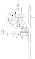
- FIG. 2 is a side view showing the configuration of the pie joint 20 according to the present embodiment.
- the pie joint 20 provided in the base material 21 includes a main body member 24 in which a groove 22 is formed, and a positioning member 26 in which 32A-1 and 32A-2 (see also FIG. 3) are formed in a fitting shape on an upper surface 26A. (Also referred to as filler).
- a positioning member 26 in which 32A-1 and 32A-2 (see also FIG. 3) are formed in a fitting shape on an upper surface 26A.
- filler two surfaces of a pair of L-shaped members 28 forming the main body member 24 are arranged to face each other to form the groove portion 22, and the upper surface 26 ⁇ / b> A of the positioning member 26 becomes the bottom surface of the groove portion 22. Composed.
- the pie joint 20 is used in an aircraft body structure as described above, and a member (a plate material 30 as an example in the present embodiment) constituting a part of the body structure is inserted into the groove portion 22.
- a member a plate material 30 as an example in the present embodiment
- the front spar 7 and the rear spar 9 are the base material 21, and the rib 11 is the plate material 30.
- the lower surface of the inserted plate member 30 is joined to the upper surface 26 ⁇ / b> A of the positioning member 26.
- the positioning member 26 has pre-formed fitting shapes 32A-1 and 32A-2 (see also FIG. 3), which will be described in detail later, on the upper surface 26A, and a plate material is formed by the fitting shapes 32A-1 and 32A-2. 30 positions are fixed at a desired position. That is, the positioning member 26 has a positioning function for the plate 30.
- the plate material 30 is bonded to the pie-type joint 20 by filling the gap between the plate material 30 and the groove 22 with an adhesive.
- the pie joint 20 is bonded to the base material 21 with an adhesive.
- the adhesion method between the base material 21 and the pie joint 20 and the adhesion method between the pie joint 20 and the plate member 30 are not particularly limited. As described above, the plate 30 is bonded to the base material 21 without using a fastener by bonding using the pie-shaped joint 20.
- the material of the pie-shaped joint 20, the base material 21, and the plate material 30 is a composite material such as carbon fiber reinforced plastic (Carbon-Fiber-Reinforced Plastic: CFRP). CFRP uses carbon fiber as a reinforcing material and synthetic resin as a matrix. Note that the material of the pie joint 20, the base material 21, and the plate material 30 is not limited to this, and a metal such as an aluminum alloy may be used.
- CFRP Carbon-Fiber-Reinforced Plastic
- the bottom surface 22 ⁇ / b> A of the groove portion 22 serves as the upper surface 26 ⁇ / b> A of the positioning member 26.
- the fitting shape 32A-1 to be fitted to the plate 30 is formed on the entire surface of the groove bottom surface 22A.
- the plate 30 is positioned on the surface. In other words, the fitting shape 32A-1 positions the plate member 30 in the width direction of the groove portion 22.
- the fitting shape 32A-1 is, for example, a symmetrical shape about the center line CL of the width of the groove portion 22 (hereinafter referred to as “groove width”). In the example of FIG. It is a type.
- the V-shaped fitting shape 32A-1 is formed in the longitudinal direction of the groove portion 22.
- the entire surface of the groove bottom surface 22A includes substantially the entire surface, for example, the fitting shape 32A-1 is not formed in the vicinity of both ends in the longitudinal direction of the groove bottom surface 22A, and is fitted in the vicinity of the center in the longitudinal direction of the groove bottom surface 22A.
- the fitting shape 32A-1 may not be formed on a part of the groove bottom surface 22A. Good.
- a fitting shape 32B-1 corresponding to the fitting shape 32A-1 of the groove bottom surface 22A is also formed on the joint surface of the plate member 30 with the pie-shaped joint 20.
- the fitting shape 32B-1 formed on the plate member 30 is also V-shaped. Since the fitting shapes 32A-1 and 32B-1 are both V-shaped, the plate 30 is smoothly fitted to the groove bottom surface 22A.
- the fitting shape 32A-1 is formed so that the plate member 30 is positioned at a predetermined position with respect to the groove width.
- the predetermined position is a position where the plate material 30 does not contact two surfaces of the L-shaped member 28 forming the groove portion 22, for example, at the center of the groove width.
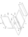
- FIG. 3 is a perspective view showing the configuration of the pie joint 20 according to the present embodiment.
- a fitting shape 32A-2 to be fitted to the plate 30 is formed on a part of the groove bottom surface 22A.
- the fitting shape 32A-2 according to the present embodiment is a notch shape as an example.
- the fitting shape 32A-2 is formed in a part of the groove bottom surface 22A, the plate material 30 is positioned at a point.
- the fitting shape 32A-2 serves as a reference position for positioning the plate member 30 with respect to the longitudinal direction of the groove portion 22, and positions the plate member 30 with respect to the longitudinal direction of the groove portion 22.
- the plate 30 is formed with a fitting shape 32B-2 to be fitted with the fitting shape 32A-2.
- the fitting shape 32B-2 according to the present embodiment is a protruding shape that can be fitted to the fitting shape 32A-2.
- the fitting shapes 32A-1 and 32A-2 of the groove bottom surface 22A and the fitting shapes 32B-1 and 32B-2 of the plate member 30 are fitted together.
- the plate member 30A is fitted only at positions that match the fitting shapes 32A-1 and 32A-2 of the groove bottom surface 22A.
- fitting shapes 32A-2 and 32B-2 shown in FIG. 3 is one as an example, but is not limited to this, and two or more may be formed at regular intervals, for example. Furthermore, the fitting shapes 32A-2 and 32B-2 are formed, for example, at approximately the center in the longitudinal direction of the groove portion 22. However, the present invention is not limited to this, and may be formed, for example, near the end portion of the groove portion 22. Good.
- the L-shaped member 28 (main body member 24) and the positioning member 26 are configured separately, but the L-shaped member 28 (main body member 24) and the positioning member 26 are integrally molded. Also good.
- mold joint 20 is not specifically limited.
- the pie-shaped joint 20 is provided in the base material 21 and has the groove portion 22 into which the plate material 30 is inserted, and joins the base material 21 and the plate material 30 by adhesion. is there.
- the pie joint 20 has a fitting shape 32A-1 that fits with the plate 30 on the entire surface of the groove bottom 22A, and a fitting shape 32A- that fits with the plate 30 on a part of the groove bottom 22A. 2 is formed.
- fitting shapes 32B-1 and 32B-2 that are fitted to the groove bottom surface 22A of the pie-shaped joint 20 are formed on the joint surface of the plate 30 with the pie-shaped joint 20.
- the plate 30 can be disposed at a desired position with respect to the groove width by the fitting shape 32A-1 of the groove bottom surface 22A. That is, the plate 30 is positioned with high accuracy in the groove width direction (A direction in FIGS. 2 and 3) by the fitting shape 32A-1 of the groove bottom surface 22A.
- the plate 30 is positioned with high accuracy in the longitudinal direction of the groove 22 (direction B in FIG. 3) by the fitting shape 32A-2 of the groove bottom 22A.
- the plate member 30 is high in the vertical direction of the groove portion 22 (C direction in FIGS. 2 and 3) simply by inserting the plate member 30 toward the groove bottom surface 22A with respect to the pie joint 20 according to the present embodiment. Positioned with accuracy.
- the pie joint 20 according to the present embodiment is joined to the pie joint 20 in an inclined manner with respect to the pie joint 20 by fitting with the plate 30 by the fitting shapes 32A-1 and 32A-2. This is also prevented.
- fitting shapes 32A-1 and 32A-2 are formed in advance on the pie joint 20, and fitting shapes 32B-1 and 32B-2 are formed on the plate 30 in advance. For this reason, since it can position by only inserting the board
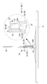
- FIG. 4 is a side view of the pi-shaped joint 20 according to the first modification of the present invention. 4 that are the same as in FIG. 2 are assigned the same reference numerals as in FIG. 2, and descriptions thereof are omitted.
- the fitting shape 32A-1 of the groove bottom surface 22A according to the first modification is asymmetrical about the groove width center line CL.
- the fitting shape 32A-1 is formed with a convex arc shape (R shape) at substantially the center, and flat shapes with different heights on the left and right sides thereof. Is done.
- the plate 30 is formed with a concave arc shape and flat shapes with different heights on the left and right sides thereof as a fitting shape 32B-1 to be fitted with the fitting shape 32A-1.
- FIG. 5 is a side view of the pi-shaped joint 20 according to the second modification of the present invention.
- the same components as those in FIG. 2 are denoted by the same reference numerals as those in FIG.
- the fitting shape 32A-1 of the groove bottom surface 22A according to the second modification is asymmetrical about the center line CL of the groove width.
- the fitting shape 32A-1 is formed with a slope (tapered shape) on one side and a flat shape having a step on the other side.
- the plate member 30 is formed with a flat shape having a slope on one side and a step on the other side as a fitting shape 32B-1 to be fitted to the fitting shape 32A-1.
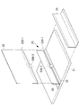
- FIG. 6 is a perspective view of a pi-shaped joint 20 according to a third modification of the present invention.
- the same components as those in FIG. 3 are denoted by the same reference numerals as those in FIG.
- a protrusion shape is formed on the positioning member 26 as the fitting shape 32A-2.
- a notch shape is formed on the plate 30 as a fitting shape 32B-2 to be fitted with the fitting shape 32A-2.
- the pie joint 20 is used for an aircraft structure.
- the present invention is not limited to this, and the pie joint 20 may be used in a structure other than an aircraft. .
- the positioning member 26 is formed with the fitting shape 32A-1 and the fitting shape 32A-2
- the plate member 30 is formed with the fitting shape 32B-1 and the fitting shape 32B-2.
- the present invention is not limited to this.
- only the fitting shape 32A-1 may be formed on the positioning member 26, and only the fitting shape 32B-1 may be formed on the plate member 30.
Landscapes
- Engineering & Computer Science (AREA)
- Mechanical Engineering (AREA)
- General Engineering & Computer Science (AREA)
- Aviation & Aerospace Engineering (AREA)
- Connection Of Plates (AREA)
- Standing Axle, Rod, Or Tube Structures Coupled By Welding, Adhesion, Or Deposition (AREA)
- Lining Or Joining Of Plastics Or The Like (AREA)
- Mutual Connection Of Rods And Tubes (AREA)
Priority Applications (6)
| Application Number | Priority Date | Filing Date | Title |
|---|---|---|---|
| US14/908,743 US10071794B2 (en) | 2013-10-02 | 2014-05-20 | Joint, and aircraft structure |
| RU2016102799A RU2636373C2 (ru) | 2013-10-02 | 2014-05-20 | Соединение и конструкция летательного аппарата |
| CA2919618A CA2919618C (en) | 2013-10-02 | 2014-05-20 | Joint, and aircraft structure |
| BR112016002134A BR112016002134A2 (pt) | 2013-10-02 | 2014-05-20 | união e estrutura de aeronave |
| CN201480043091.5A CN105452679B (zh) | 2013-10-02 | 2014-05-20 | 接头及航空机结构 |
| EP14851380.7A EP3015721B1 (en) | 2013-10-02 | 2014-05-20 | Joint, and aircraft structure |
Applications Claiming Priority (2)
| Application Number | Priority Date | Filing Date | Title |
|---|---|---|---|
| JP2013207663A JP6090931B2 (ja) | 2013-10-02 | 2013-10-02 | 継手及び航空機構造 |
| JP2013-207663 | 2013-10-02 |
Publications (1)
| Publication Number | Publication Date |
|---|---|
| WO2015049895A1 true WO2015049895A1 (ja) | 2015-04-09 |
Family
ID=52778492
Family Applications (1)
| Application Number | Title | Priority Date | Filing Date |
|---|---|---|---|
| PCT/JP2014/063384 Ceased WO2015049895A1 (ja) | 2013-10-02 | 2014-05-20 | 継手及び航空機構造 |
Country Status (8)
| Country | Link |
|---|---|
| US (1) | US10071794B2 (enExample) |
| EP (1) | EP3015721B1 (enExample) |
| JP (1) | JP6090931B2 (enExample) |
| CN (1) | CN105452679B (enExample) |
| BR (1) | BR112016002134A2 (enExample) |
| CA (1) | CA2919618C (enExample) |
| RU (1) | RU2636373C2 (enExample) |
| WO (1) | WO2015049895A1 (enExample) |
Families Citing this family (13)
| Publication number | Priority date | Publication date | Assignee | Title |
|---|---|---|---|---|
| US9199715B2 (en) * | 2013-10-10 | 2015-12-01 | The Boeing Company | Self-aligning fitting assemblies and systems and methods including the same |
| WO2018001425A1 (en) * | 2016-06-28 | 2018-01-04 | Vestas Wind Systems A/S | Manufacture of a wind turbine blade |
| US10696373B2 (en) * | 2016-09-13 | 2020-06-30 | The Boeing Company | Aircraft wings and aircraft including such aircraft wings |
| US10703419B2 (en) * | 2017-05-19 | 2020-07-07 | Divergent Technologies, Inc. | Apparatus and methods for joining panels |
| US10605631B2 (en) * | 2017-08-03 | 2020-03-31 | Sikorsky Aircraft Corporation | Structural pi joint with integrated fiber optic sensing |
| US11939105B2 (en) * | 2017-08-29 | 2024-03-26 | Goodrich Corporation | 3D woven conformable tank |
| US11091266B2 (en) | 2017-08-29 | 2021-08-17 | Goodrich Corporation | Conformable tank fabricated using additive manufacturing |
| US10703481B2 (en) | 2017-08-29 | 2020-07-07 | Goodrich Corporation | Conformable tank with sandwich structure walls |
| US10816138B2 (en) | 2017-09-15 | 2020-10-27 | Goodrich Corporation | Manufacture of a conformable pressure vessel |
| CN109236819B (zh) * | 2018-09-19 | 2023-11-24 | 苏州富强科技有限公司 | 用于对l形零件进行定位保压的设备 |
| WO2020208802A1 (ja) * | 2019-04-12 | 2020-10-15 | 株式会社Ihiエアロスペース | 継手構造体及びその組立方法 |
| US12220877B2 (en) | 2022-01-04 | 2025-02-11 | Rohr, Inc. | Component with monolithic structure having blind interface joint |
| GB2617556A (en) * | 2022-04-08 | 2023-10-18 | Airbus Operations Ltd | Wing-box structure |
Citations (4)
| Publication number | Priority date | Publication date | Assignee | Title |
|---|---|---|---|---|
| US7205066B1 (en) * | 2002-05-23 | 2007-04-17 | Rohr, Inc. | Structural element with rib-receiving member |
| JP2012528994A (ja) * | 2009-06-03 | 2012-11-15 | カーゲーテー・グラフィート・テヒノロギー・ゲゼルシャフト・ミト・ベシュレンクテル・ハフツング | 多部材より成るグラファイト構造要素への、複数の特殊グラファイト部材の形状および力一体的な結合 |
| US8393871B2 (en) * | 2011-07-19 | 2013-03-12 | General Electric Company | Wind turbine blade shear web connection assembly |
| US8403586B2 (en) | 2004-11-30 | 2013-03-26 | The Boeing Company | Determinant assembly features for vehicle structures |
Family Cites Families (25)
| Publication number | Priority date | Publication date | Assignee | Title |
|---|---|---|---|---|
| US4671470A (en) * | 1985-07-15 | 1987-06-09 | Beech Aircraft Corporation | Method for fastening aircraft frame elements to sandwich skin panels covering same using woven fiber connectors |
| US5474635A (en) * | 1994-03-07 | 1995-12-12 | United Technologies Corporation | Joining non-coplanar panels and structures of fiber reinforced composites |
| JP3667200B2 (ja) * | 2000-07-12 | 2005-07-06 | 株式会社イシモク・コーポレーション | 木製品の連結構造 |
| US6374570B1 (en) * | 2000-08-25 | 2002-04-23 | Lockheed Martin Corporation | Apparatus and method for joining dissimilar materials to form a structural support member |
| US6849150B1 (en) * | 2001-01-16 | 2005-02-01 | Lockheed Martin Corporation | System and method of forming structural assemblies with 3-D woven joint pre-forms |
| US6863767B2 (en) * | 2001-08-23 | 2005-03-08 | Lockheed Martin Corporation | Paste-bond clevis joint |
| US6749155B2 (en) | 2002-09-13 | 2004-06-15 | The Boeing Company | Composite assembly with integrated composite joints |
| JP3659249B2 (ja) * | 2002-12-27 | 2005-06-15 | 住友金属工業株式会社 | 鋼矢板および矢板式鋼製壁 |
| JP2004216672A (ja) * | 2003-01-14 | 2004-08-05 | Pearl Mannequin:Kk | 中空合体式成型体及び成形型 |
| US7037568B1 (en) * | 2003-07-15 | 2006-05-02 | Rogers Terry W | Joining member for mechanically joining a skin to a supporting rib |
| US8272618B2 (en) | 2004-11-30 | 2012-09-25 | The Boeing Company | Minimum bond thickness assembly feature assurance |
| US7555873B2 (en) | 2004-11-30 | 2009-07-07 | The Boeing Company | Self-locating feature for a pi-joint assembly |
| US7393488B2 (en) * | 2005-05-25 | 2008-07-01 | The Boeing Company | Methods of joining structures and joints formed thereby |
| US7670527B2 (en) * | 2006-05-09 | 2010-03-02 | Lockheed Martin Corporation | Failsafe injected adhesive joint |
| US8082667B2 (en) * | 2007-05-31 | 2011-12-27 | The Boeing Company | Apparatus and methods for securing a first structural member and a second structural member to one another |
| EP2373473B1 (de) | 2008-12-04 | 2017-06-21 | Covestro Deutschland AG | Verklebtes kunststoff-verbundbauteil, verfahren zur herstellung dieses sowie bauteil aus diesem. |
| FR2954200B1 (fr) | 2009-12-23 | 2012-03-02 | Snecma | Procede de realisation d'un renfort metallique d'aube de turbomachine |
| WO2011096159A1 (ja) * | 2010-02-02 | 2011-08-11 | パナソニック株式会社 | 電池収納ケース及びこれを備えた電池パック |
| US9073267B1 (en) * | 2010-03-10 | 2015-07-07 | The Boeing Company | Method of assembling panels and adhesively bonded joints used therein |
| RU103588U1 (ru) * | 2010-08-20 | 2011-04-20 | Владимир Владимирович Жебелев | Клеевое соединение транца с днищем |
| DE102010064060A1 (de) * | 2010-12-23 | 2012-06-28 | Airbus Operations Gmbh | Befestigungsanordnung zum Befestigen einer Komponente eines Luft- oder Raumfahrzeuges, Klebehalter einer derartigen Befestigungsanordnung und Luft- oder Raumfahrzeug mit einer derartigen Befestigungsanordnung und/oder einem derartigen Klebehalter |
| US8985515B2 (en) * | 2010-12-28 | 2015-03-24 | Textron Innovations Inc. | Multi-directional load joint system |
| CN202244075U (zh) * | 2011-06-03 | 2012-05-30 | 哈尔滨飞机工业集团有限责任公司 | 一种框与壁板的连接结构 |
| US9017510B2 (en) * | 2011-12-13 | 2015-04-28 | The Boeing Company | Method and apparatus for fabricating large scale integrated airfoils |
| US9681527B2 (en) * | 2013-03-29 | 2017-06-13 | The Boeing Company | Method and apparatus for providing a current return network in an aircraft structure |
-
2013
- 2013-10-02 JP JP2013207663A patent/JP6090931B2/ja active Active
-
2014
- 2014-05-20 RU RU2016102799A patent/RU2636373C2/ru active
- 2014-05-20 EP EP14851380.7A patent/EP3015721B1/en active Active
- 2014-05-20 WO PCT/JP2014/063384 patent/WO2015049895A1/ja not_active Ceased
- 2014-05-20 CA CA2919618A patent/CA2919618C/en not_active Expired - Fee Related
- 2014-05-20 BR BR112016002134A patent/BR112016002134A2/pt active Search and Examination
- 2014-05-20 US US14/908,743 patent/US10071794B2/en active Active
- 2014-05-20 CN CN201480043091.5A patent/CN105452679B/zh not_active Expired - Fee Related
Patent Citations (4)
| Publication number | Priority date | Publication date | Assignee | Title |
|---|---|---|---|---|
| US7205066B1 (en) * | 2002-05-23 | 2007-04-17 | Rohr, Inc. | Structural element with rib-receiving member |
| US8403586B2 (en) | 2004-11-30 | 2013-03-26 | The Boeing Company | Determinant assembly features for vehicle structures |
| JP2012528994A (ja) * | 2009-06-03 | 2012-11-15 | カーゲーテー・グラフィート・テヒノロギー・ゲゼルシャフト・ミト・ベシュレンクテル・ハフツング | 多部材より成るグラファイト構造要素への、複数の特殊グラファイト部材の形状および力一体的な結合 |
| US8393871B2 (en) * | 2011-07-19 | 2013-03-12 | General Electric Company | Wind turbine blade shear web connection assembly |
Non-Patent Citations (1)
| Title |
|---|
| See also references of EP3015721A4 |
Also Published As
| Publication number | Publication date |
|---|---|
| EP3015721A4 (en) | 2016-07-13 |
| US10071794B2 (en) | 2018-09-11 |
| US20160244140A1 (en) | 2016-08-25 |
| JP2015072042A (ja) | 2015-04-16 |
| EP3015721A1 (en) | 2016-05-04 |
| CN105452679B (zh) | 2019-01-04 |
| RU2636373C2 (ru) | 2017-11-22 |
| CN105452679A (zh) | 2016-03-30 |
| CA2919618A1 (en) | 2015-04-09 |
| CA2919618C (en) | 2019-09-24 |
| BR112016002134A2 (pt) | 2017-08-01 |
| JP6090931B2 (ja) | 2017-03-08 |
| RU2016102799A (ru) | 2017-11-10 |
| EP3015721B1 (en) | 2021-07-14 |
Similar Documents
| Publication | Publication Date | Title |
|---|---|---|
| JP6090931B2 (ja) | 継手及び航空機構造 | |
| US10040538B2 (en) | Joint, and aircraft structure | |
| CN106662070B (zh) | 用于风力涡轮机叶片的叶尖系统 | |
| US9193433B2 (en) | Double-sided stiffened composite panel and method for producing such a panel | |
| US8915471B2 (en) | Bonded splice joint | |
| CN102612466B (zh) | 包括机身段和接合部件的机身元件 | |
| US10648451B2 (en) | Method for manufacturing a rotor blade of a wind power plant, rotor blade and wind power plant | |
| ES2626352T3 (es) | Herramienta híbrida para curar piezas de material compuesto | |
| ES2738109T3 (es) | Disposición de unión de los cajones laterales de un estabilizador horizontal de cola con un cajón central tubular y procedimiento de fabricación de dicho cajón | |
| JP2009519861A5 (enExample) | ||
| EP3098440B1 (en) | A wind turbine blade and a method of assembling a wind turbine blade and a spar cap connection piece | |
| JP6255172B2 (ja) | 複合構造パネルおよび航空機胴体 | |
| WO2013191093A1 (ja) | Frp製部材 | |
| CN105073577B (zh) | 用于飞行器机身的加强件、用于制造飞行器机身的加强件的方法以及装有这种加强件的飞行器机身 | |
| CN103600440B (zh) | 复合材料翼梁的芯模 | |
| JP2019157975A (ja) | ダブルスキン構造体及びその製造方法 | |
| CN108100231A (zh) | 一种直升机平尾接头 | |
| JP2014015002A (ja) | コーナー接合部品 | |
| JP2019167063A (ja) | 車両用ホイール | |
| JP7543168B2 (ja) | 接着継手の製造方法 | |
| KR20170107601A (ko) | 접합구조를 갖는 복합재 부품 | |
| US20250001719A1 (en) | Filler | |
| JP6025246B2 (ja) | 翼用リブ | |
| JP2021049674A (ja) | 複合材の継手部材及び継手構造体 | |
| JP2014028553A (ja) | 車両用サイドパネル構造体 |
Legal Events
| Date | Code | Title | Description |
|---|---|---|---|
| WWE | Wipo information: entry into national phase |
Ref document number: 201480043091.5 Country of ref document: CN |
|
| 121 | Ep: the epo has been informed by wipo that ep was designated in this application |
Ref document number: 14851380 Country of ref document: EP Kind code of ref document: A1 |
|
| ENP | Entry into the national phase |
Ref document number: 2919618 Country of ref document: CA |
|
| WWE | Wipo information: entry into national phase |
Ref document number: 2014851380 Country of ref document: EP |
|
| WWE | Wipo information: entry into national phase |
Ref document number: 14908743 Country of ref document: US |
|
| REG | Reference to national code |
Ref country code: BR Ref legal event code: B01A Ref document number: 112016002134 Country of ref document: BR |
|
| NENP | Non-entry into the national phase |
Ref country code: DE |
|
| ENP | Entry into the national phase |
Ref document number: 2016102799 Country of ref document: RU Kind code of ref document: A |
|
| ENP | Entry into the national phase |
Ref document number: 112016002134 Country of ref document: BR Kind code of ref document: A2 Effective date: 20160129 |