WO2015045590A1 - 表示装置 - Google Patents
表示装置 Download PDFInfo
- Publication number
- WO2015045590A1 WO2015045590A1 PCT/JP2014/069325 JP2014069325W WO2015045590A1 WO 2015045590 A1 WO2015045590 A1 WO 2015045590A1 JP 2014069325 W JP2014069325 W JP 2014069325W WO 2015045590 A1 WO2015045590 A1 WO 2015045590A1
- Authority
- WO
- WIPO (PCT)
- Prior art keywords
- display
- display unit
- unit
- display module
- display device
- Prior art date
- Legal status (The legal status is an assumption and is not a legal conclusion. Google has not performed a legal analysis and makes no representation as to the accuracy of the status listed.)
- Ceased
Links
Images





Classifications
-
- G—PHYSICS
- G02—OPTICS
- G02B—OPTICAL ELEMENTS, SYSTEMS OR APPARATUS
- G02B27/00—Optical systems or apparatus not provided for by any of the groups G02B1/00 - G02B26/00, G02B30/00
- G02B27/10—Beam splitting or combining systems
- G02B27/14—Beam splitting or combining systems operating by reflection only
- G02B27/144—Beam splitting or combining systems operating by reflection only using partially transparent surfaces without spectral selectivity
-
- G—PHYSICS
- G02—OPTICS
- G02B—OPTICAL ELEMENTS, SYSTEMS OR APPARATUS
- G02B7/00—Mountings, adjusting means, or light-tight connections, for optical elements
- G02B7/18—Mountings, adjusting means, or light-tight connections, for optical elements for prisms; for mirrors
- G02B7/182—Mountings, adjusting means, or light-tight connections, for optical elements for prisms; for mirrors for mirrors
-
- G—PHYSICS
- G02—OPTICS
- G02F—OPTICAL DEVICES OR ARRANGEMENTS FOR THE CONTROL OF LIGHT BY MODIFICATION OF THE OPTICAL PROPERTIES OF THE MEDIA OF THE ELEMENTS INVOLVED THEREIN; NON-LINEAR OPTICS; FREQUENCY-CHANGING OF LIGHT; OPTICAL LOGIC ELEMENTS; OPTICAL ANALOGUE/DIGITAL CONVERTERS
- G02F1/00—Devices or arrangements for the control of the intensity, colour, phase, polarisation or direction of light arriving from an independent light source, e.g. switching, gating or modulating; Non-linear optics
- G02F1/01—Devices or arrangements for the control of the intensity, colour, phase, polarisation or direction of light arriving from an independent light source, e.g. switching, gating or modulating; Non-linear optics for the control of the intensity, phase, polarisation or colour
- G02F1/13—Devices or arrangements for the control of the intensity, colour, phase, polarisation or direction of light arriving from an independent light source, e.g. switching, gating or modulating; Non-linear optics for the control of the intensity, phase, polarisation or colour based on liquid crystals, e.g. single liquid crystal display cells
- G02F1/133—Constructional arrangements; Operation of liquid crystal cells; Circuit arrangements
- G02F1/1333—Constructional arrangements; Manufacturing methods
- G02F1/133308—Support structures for LCD panels, e.g. frames or bezels
-
- G—PHYSICS
- G02—OPTICS
- G02F—OPTICAL DEVICES OR ARRANGEMENTS FOR THE CONTROL OF LIGHT BY MODIFICATION OF THE OPTICAL PROPERTIES OF THE MEDIA OF THE ELEMENTS INVOLVED THEREIN; NON-LINEAR OPTICS; FREQUENCY-CHANGING OF LIGHT; OPTICAL LOGIC ELEMENTS; OPTICAL ANALOGUE/DIGITAL CONVERTERS
- G02F1/00—Devices or arrangements for the control of the intensity, colour, phase, polarisation or direction of light arriving from an independent light source, e.g. switching, gating or modulating; Non-linear optics
- G02F1/01—Devices or arrangements for the control of the intensity, colour, phase, polarisation or direction of light arriving from an independent light source, e.g. switching, gating or modulating; Non-linear optics for the control of the intensity, phase, polarisation or colour
- G02F1/13—Devices or arrangements for the control of the intensity, colour, phase, polarisation or direction of light arriving from an independent light source, e.g. switching, gating or modulating; Non-linear optics for the control of the intensity, phase, polarisation or colour based on liquid crystals, e.g. single liquid crystal display cells
- G02F1/133—Constructional arrangements; Operation of liquid crystal cells; Circuit arrangements
- G02F1/1333—Constructional arrangements; Manufacturing methods
- G02F1/1335—Structural association of cells with optical devices, e.g. polarisers or reflectors
- G02F1/133553—Reflecting elements
- G02F1/133555—Transflectors
-
- G—PHYSICS
- G02—OPTICS
- G02F—OPTICAL DEVICES OR ARRANGEMENTS FOR THE CONTROL OF LIGHT BY MODIFICATION OF THE OPTICAL PROPERTIES OF THE MEDIA OF THE ELEMENTS INVOLVED THEREIN; NON-LINEAR OPTICS; FREQUENCY-CHANGING OF LIGHT; OPTICAL LOGIC ELEMENTS; OPTICAL ANALOGUE/DIGITAL CONVERTERS
- G02F1/00—Devices or arrangements for the control of the intensity, colour, phase, polarisation or direction of light arriving from an independent light source, e.g. switching, gating or modulating; Non-linear optics
- G02F1/01—Devices or arrangements for the control of the intensity, colour, phase, polarisation or direction of light arriving from an independent light source, e.g. switching, gating or modulating; Non-linear optics for the control of the intensity, phase, polarisation or colour
- G02F1/13—Devices or arrangements for the control of the intensity, colour, phase, polarisation or direction of light arriving from an independent light source, e.g. switching, gating or modulating; Non-linear optics for the control of the intensity, phase, polarisation or colour based on liquid crystals, e.g. single liquid crystal display cells
- G02F1/133—Constructional arrangements; Operation of liquid crystal cells; Circuit arrangements
- G02F1/1333—Constructional arrangements; Manufacturing methods
- G02F1/133308—Support structures for LCD panels, e.g. frames or bezels
- G02F1/133322—Mechanical guidance or alignment of LCD panel support components
-
- G—PHYSICS
- G02—OPTICS
- G02F—OPTICAL DEVICES OR ARRANGEMENTS FOR THE CONTROL OF LIGHT BY MODIFICATION OF THE OPTICAL PROPERTIES OF THE MEDIA OF THE ELEMENTS INVOLVED THEREIN; NON-LINEAR OPTICS; FREQUENCY-CHANGING OF LIGHT; OPTICAL LOGIC ELEMENTS; OPTICAL ANALOGUE/DIGITAL CONVERTERS
- G02F1/00—Devices or arrangements for the control of the intensity, colour, phase, polarisation or direction of light arriving from an independent light source, e.g. switching, gating or modulating; Non-linear optics
- G02F1/01—Devices or arrangements for the control of the intensity, colour, phase, polarisation or direction of light arriving from an independent light source, e.g. switching, gating or modulating; Non-linear optics for the control of the intensity, phase, polarisation or colour
- G02F1/13—Devices or arrangements for the control of the intensity, colour, phase, polarisation or direction of light arriving from an independent light source, e.g. switching, gating or modulating; Non-linear optics for the control of the intensity, phase, polarisation or colour based on liquid crystals, e.g. single liquid crystal display cells
- G02F1/133—Constructional arrangements; Operation of liquid crystal cells; Circuit arrangements
- G02F1/1333—Constructional arrangements; Manufacturing methods
- G02F1/1335—Structural association of cells with optical devices, e.g. polarisers or reflectors
- G02F1/133553—Reflecting elements
- G02F1/133555—Transflectors
- G02F1/133557—Half-mirrors
-
- G—PHYSICS
- G02—OPTICS
- G02F—OPTICAL DEVICES OR ARRANGEMENTS FOR THE CONTROL OF LIGHT BY MODIFICATION OF THE OPTICAL PROPERTIES OF THE MEDIA OF THE ELEMENTS INVOLVED THEREIN; NON-LINEAR OPTICS; FREQUENCY-CHANGING OF LIGHT; OPTICAL LOGIC ELEMENTS; OPTICAL ANALOGUE/DIGITAL CONVERTERS
- G02F1/00—Devices or arrangements for the control of the intensity, colour, phase, polarisation or direction of light arriving from an independent light source, e.g. switching, gating or modulating; Non-linear optics
- G02F1/01—Devices or arrangements for the control of the intensity, colour, phase, polarisation or direction of light arriving from an independent light source, e.g. switching, gating or modulating; Non-linear optics for the control of the intensity, phase, polarisation or colour
- G02F1/13—Devices or arrangements for the control of the intensity, colour, phase, polarisation or direction of light arriving from an independent light source, e.g. switching, gating or modulating; Non-linear optics for the control of the intensity, phase, polarisation or colour based on liquid crystals, e.g. single liquid crystal display cells
- G02F1/133—Constructional arrangements; Operation of liquid crystal cells; Circuit arrangements
- G02F1/1333—Constructional arrangements; Manufacturing methods
- G02F1/1335—Structural association of cells with optical devices, e.g. polarisers or reflectors
- G02F1/13356—Structural association of cells with optical devices, e.g. polarisers or reflectors characterised by the placement of the optical elements
- G02F1/133562—Structural association of cells with optical devices, e.g. polarisers or reflectors characterised by the placement of the optical elements on the viewer side
Definitions
- the present invention relates to a display device including a display module and a translucent member having a transmissive mirror portion.
- the transmissive mirror unit is made of a reflective or scattering material capable of transmitting light, transmits part of light, and reflects or scatters part of light.
- Patent Document 1 discloses a portable electronic device in which a mirror surface portion in which a half mirror is formed as a transmissive mirror portion is assembled on a front surface portion of a housing.
- a holder for accommodating a display module including a liquid crystal display is provided behind the half mirror in the portable electronic device so as to be in close contact with the half mirror or with a slight gap between the half mirror.
- Patent Document 2 discloses a terminal device in which a blind sheet is attached to part or all of a display in a display module or a transparent panel that accommodates the display inside.
- a half mirror is formed as a transmissive mirror portion on part or all of one surface of the translucent film serving as a support.
- Patent Document 3 discloses a display body including a display unit including a liquid crystal panel and a magic mirror unit stacked on the display unit.
- the liquid crystal panel is provided with a status display area and a content display area, and a transparent transmission area is formed in a portion of the magic mirror portion located on the status display area.
- a translucent region having a reflective film is formed as a transmissive mirror portion at a portion of the magic mirror portion located on the content display region.
- the conventional display device has a problem that the positional accuracy of the transmissive mirror portion with respect to the image displayed on the display screen is low.
- the display module is disposed in close contact with the half mirror or with a slight gap between the display module and the half mirror.
- a transmissive mirror an optical member having a transmissive mirror in a housing as in Patent Document 1
- the transmissive mirror is separated from the display surface, it is caused by parallax. The image is misaligned.
- a polarizing plate is generally provided on the surface of a display such as a liquid crystal display. For this reason, for example, when a transparent mirror is bonded to the display surface as in Patent Document 1, the transparent mirror is bonded to the polarizing plate.
- the positioning of the display unit including the liquid crystal panel as in Patent Document 3 and the magic mirror unit, the half mirror provided on the front surface of the housing as in Patent Document 1, and the space in the housing It is also difficult to position the holder with the display module stored in the holder.
- Patent Document 3 when a liquid crystal panel is provided with two display parts (display areas) and a transmissive area and a semi-transmissive area are provided at positions located on the respective display parts in the magic mirror part, Due to tolerances at the time of assembly, thermal expansion / shrinkage, etc., a positional deviation between the boundary line between the transmission region and the semi-transmission region and each display region is likely to occur.
- a part of an image (video) displayed via one area for example, a translucent area
- the other area for example, a transparent area
- the present invention has been made in view of the above-described problems, and suppresses a positional shift between one of the two display units in the display module and the transmissive mirror disposed corresponding to the display unit. It is an object to provide a display device that can be used.
- a display device faces a display module having a display surface provided with first and second display portions, and the second display portion.
- a translucent member having a translucent mirror that covers the second display unit; and a positioning member that aligns the display module and the translucent member, the display module and the translucent member Are in contact with the positioning member at the end surface on the second display unit side of the first and second display units, respectively, while the end surface on the first display unit side is in contact with nowhere. There is no free end.
- the translucent member provided with the transmissive mirror portion can be provided very close to the display surface of the display module without directly attaching the transmissive mirror to the polarizing plate. For this reason, the parallax-less effect equivalent to the case where a transmissive mirror is directly attached to a polarizing plate can be obtained. Further, the positional deviation between the boundary line between the first display unit and the second display unit and the end of the transmissive mirror can be suppressed rather than directly attaching the transmissive mirror to the polarizing plate.
- the display module and the translucent member can be easily positioned.
- the second display unit and the transmissive mirror unit are arranged on the positioning member side with a small amount of displacement, the positional deviation of the transmissive mirror unit with respect to the second display unit is suppressed, The processing dimension accuracy and assembly accuracy of the display device can be improved.
- the end surface on the first display unit side is a free end, variation in displacement of the end surface on the first display unit side due to thermal expansion or contraction is caused. (Position misalignment) can be prevented from being applied to the second display unit side (transmission mirror unit side).
- the positional deviation between the second display unit and the transmissive mirror unit is suppressed, and the alignment accuracy between the second display unit and the transmissive mirror unit is improved. Can be improved.
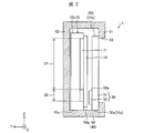
- (A) is a front view which shows schematic structure of the display apparatus which concerns on Embodiment 1 of this invention
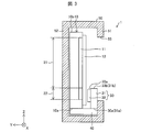
- (b) is AA arrow sectional drawing of the display apparatus shown to (a). It is sectional drawing which shows schematic structure of the display apparatus which concerns on the modification of Embodiment 1 of this invention. It is sectional drawing which shows schematic structure of the display apparatus which concerns on Embodiment 2 of this invention. It is sectional drawing which shows schematic structure of the display apparatus which concerns on the modification of Embodiment 2 of this invention.
- (A) is a front view which shows schematic structure of the principal part of the display apparatus which concerns on Embodiment 3 of this invention
- (b) is schematic structure of the principal part of the display apparatus which concerns on Embodiment 3 of this invention.
- (A) is a front view which shows schematic structure of the principal part of the display module in the display apparatus which concerns on Embodiment 6 of this invention
- (b) is the principal part of the display apparatus which concerns on Embodiment 6 of this invention. It is sectional drawing which shows schematic structure.
- Embodiment 1 Hereinafter, embodiments of the present invention will be described with reference to FIGS. 1A and 1B and FIG.
- FIG. 1A is a front view showing a schematic configuration of the display device 1 according to the present embodiment
- FIG. 1B is an AA line of the display device 1 shown in FIG. It is arrow sectional drawing.
- the display device 1 includes a display module 10, an optical member 30, a positioning member 40 (positioning mechanism), and a housing 50.
- the display device 1 is a display device that has both a transmissive display area and a semi-transmissive display area.
- the Z-axis direction is the row direction (upward) of the display module 10, and the two horizontal directions perpendicular to the Z-axis are the X-axis direction and the Y-axis.
- the direction of the display module 10 is described as the X-axis direction.
- the optical member 30 is a translucent member in which a translucent mirror portion 32 is provided on at least a part of a translucent support substrate 31.
- a transmissive mirror portion 32 is provided on a part of the support substrate 31.
- the support substrate 31 is a highly transparent substrate such as glass or acrylic.
- the transmissive mirror unit 32 is made of a reflective or scattering material capable of transmitting light, transmits part of light, and reflects or scatters part of light.
- the transmissive mirror portion 32 for example, a half mirror (semi-transparent mirror) formed by vapor-depositing a metal such as aluminum can be used.
- the transmissive mirror part 32 is formed by sticking, for example, a sheet-like transmissive mirror member, which is provided with an adhesive layer or the like and is formed by depositing metal on a support different from the support substrate 31 to the support substrate 31. Alternatively, it may be formed by directly depositing a metal on the support substrate 31.
- the optical member 30 is provided on the display surface side of the display module 10 so as to face the display module 10. Further, the transmissive mirror unit 32 is provided on the support substrate 31 on the display module 10 side so as to face the second display unit 22.
- the display module 10 includes a display unit 11 and a polarizing plate 12 (front side polarizing plate) provided on the display surface side of the display unit 11. Although not shown, the display module 10 has a polarizing plate (back side polarizing plate) provided on the side opposite to the display surface of the display unit 11, a backlight frame provided with a backlight, and an image on the display unit 11. A configuration necessary for displaying an image (video) on the display unit 11 such as a circuit board for displaying (video) is provided.
- a liquid crystal panel is used for the display unit 11 of the display module 10.
- the display panel used for the display unit 11 is not limited to a liquid crystal panel, and may be an organic EL (electroluminescence) panel, an inorganic EL panel, a plasma panel, or the like. Therefore, a front side polarizing plate, a back side polarizing plate, a backlight and the like are not essential.
- the display module 10 includes a first display unit 21 (first display unit, main region) and a second display unit 22 (second display unit, sub-region) on the same surface (same display surface). That is, the display surface of the display unit 11 is divided into a first display unit 21 and a second display unit 22.
- a first video based on a first video signal is displayed on the first display unit 21.
- the second display unit 22 displays a second video based on a second video signal different from the first display unit 21.
- the first video is, for example, a main content video
- the second video is, for example, a sub content video.
- the aspect ratio of the first display unit 21 is, for example, 16: 9, and the first display unit 21 can display a full HD (High Definition) video. Further, the aspect ratio of the second display unit 22 is 16: 1.
- the first display unit 21 (for example, 16: 9 region) is a transmissive display region
- the second display unit 22 (for example, 16: 1 region) is a semi-transmissive display region.
- a transmissive mirror unit 32 in the optical member 30 is disposed on the display surface side of the second display unit 22 in the display module 10.
- the height in the Z-axis direction from the surface of the positioning member 40 to the far end (upper end portion 32 a) of the transmissive mirror portion 32 in the optical member 30 is from the surface of the positioning member 40.
- the first display unit 21 and the second display unit 22 to the far end of the second display unit 22 Is set to be slightly above the upper end portion 32a of the transmissive mirror portion 32).
- the support substrate 31 fixes the display module 10 and the optical member 30 to the positioning member 40 when the display device 1 is viewed from the observer side.
- the first display unit 21 and the second display unit 22 are formed in a size that covers the first display unit 21 and the second display unit 22.
- the transmissive mirror unit 32 is formed to have a size that covers the second display unit 22 when the display device 1 is viewed from the viewer side. That is, the support substrate 31 is formed in a size that covers the 16:10 region when the first display unit 21 is a 16: 9 region and the second display unit 22 is a 16: 1 region, for example.
- the image displayed on the first display unit 21 can be confirmed over a region of the support substrate 31 where the transmissive mirror unit 32 is not provided.
- the image displayed on the second display unit 22 can be confirmed through the transmissive mirror unit 32.
- the positioning member 40 is used for alignment between the display module 10 and the optical member 30. As shown in FIG. 1B, the positioning member 40 is an end face 10a, 30a on the second display portion 22 side in the display module 10 and the optical member 30 (in other words, an optical member on the transflective region side). 30 is provided in contact with the end surfaces 10a and 30a) on the side where the transmissive mirror portion 32 is formed. The end surface 30a on the second display portion 22 side in the optical member 30 specifically indicates the end surface 31a on the second display portion 22 side in the support substrate 31.
- the display module 10 and the optical member 30 according to the present embodiment are fixed to the positioning member 40 at the end surfaces 10a and 30a on the second display unit 22 side of the first display unit 21 and the second display unit 22, respectively.
- the end surfaces 10b and 30b on the opposite side (opposite side) to the end surfaces 10a and 30a on the second display unit 22 side that is, the end surfaces 10b and 30b on the first display unit 21 side
- gaps are provided between the housing 50 and the end faces 10b and 30b on the first display portion 21 side of the display module 10 and the optical member 30, respectively.
- the display module 10 and the optical member 30 are supported by the housing 50 and the positioning member 40 at portions other than the end surfaces 10b and 30b on the first display unit 21 side, respectively.
- a plate member made of a resin or metal material is used as the positioning member 40.
- the plate member made of a resin material include a plastic plate.
- the plate member made of a metal material include a plate made of a metal such as aluminum or iron.
- the method for fixing the display module 10 and the optical member 30 to the positioning member 40 is not particularly limited, and various known fixing methods such as adhesion, screwing, and fitting can be used.
- a groove (fitting groove) (not shown) may be provided in the positioning member 40, and the display module 10 and the optical member 30 may be fitted into the groove.
- the positioning member 40 may be provided with a plurality of protrusions as stoppers. In this case, attaching and detaching and fixing of the display module 10 and the optical member 30 to the positioning member 40 can be easily performed by giving the protrusion a biasing force that biases the display module 10 and the optical member 30.
- the display module 10, the optical member 30, and the positioning member 40 are accommodated in the housing 50.
- the casing 50 is provided, for example, on the front side casing 51 (first casing) provided on the display surface side of the display module 10 and on the back side (opposite to the observer side) of the display module 10.
- a rear-side casing 52 (second casing).
- the front casing 51 is provided with an opening 53 through which an image displayed on the display device 1 is transmitted.
- one of the front-side casing 51 and the back-side casing 52 is formed in an L-shaped cross section.
- the front-side casing 51 and the back-side casing 52 include the display module 10 and the optical member. 30 and the positioning member 40 are sandwiched.
- a slight gap is provided between the housing 50 and the display module 10, the optical member 30, and the positioning member 40.
- the display module 10, the optical member 30, and the positioning member 40 are attached to the housing 50.
- the display module 10, the optical member 30, and the positioning member 40 are partially supported by the housing 50 (for example, point contact with the housing 50) by a provided support unit (not shown).
- the transmissive mirror unit 32 is desirably provided as close as possible to the second display unit 22 of the display module 10.
- the transmissive mirror unit 32 is desirably provided on the display module 10 side of the support substrate 31 so as to face the second display unit 22, and the display module 10 and the optical member. 30 is preferably provided as close as possible in the Y-axis direction shown in FIG.
- glass is suitably used for the display panel substrate in the display module 10 or the support substrate 31 in the optical member 30, for example.
- the thermal expansion or contraction assumed for the actual use of glass is 1 line in the Z-axis direction (0.1% (1 line / 1080 lines) in a 16: 9 full HD area such as TV images), for example, a 30-inch class TV ( (Television) is about 0.3 mm) ( ⁇ 0.15 mm). Accordingly, when viewing (observation) within a vertical viewing angle of about 20 ° or less, in order to suppress a positional shift due to thermal expansion or thermal contraction within one pixel, the display module 10 and the optical member 30 are moved from tan 20 °.
- the gap is preferably suppressed to about 0.5 mm.
- the gap between the display module 10 and the transmissive mirror unit 32 is preferably 0.5 mm or less for the 30-type display device 1, for example, 1 mm or less (0.5 mm for the 60-type display device 1).
- X60 type / 30 type is preferably 0.5 mm or less for the 30-type display device 1, for example, 1 mm or less (0.5 mm for the 60-type display device 1).
- the support substrate 31 is provided with the transmissive mirror unit 32 facing the second display unit 22, and the display module 10 and the support substrate 31 on the transmissive mirror unit 32 side.
- the end surfaces 10a and 30a of the first member were fixed to the positioning member 40.
- the optical member 30 provided with the transmissive mirror portion 32 can be used as the display surface (display) of the display module 10 without directly attaching a transmissive mirror to the polarizing plate 12. Can be provided very close to the surface. Thereby, the parallax-less effect equivalent to the case where a transparent mirror is directly attached to the polarizing plate 12 can be obtained.
- the video end between the first display unit 21 and the second display unit 22 (in other words, the first display unit 21 and the first display unit 21). 2) and a misalignment between the end of the transmissive mirror can be suppressed.
- the gap between the display module 10 and the optical member 30 is within the above-described range.
- the display module 10 and the optical member 30 provided with the transmissive mirror portion 32 are fixed by the positioning member 40, thereby easily positioning the display module 10 and the optical member 30. It can be carried out.
- the positional displacement is shifted to the positioning member 40 side with a small amount of displacement.
- a transmissive mirror portion 32 to be suppressed is disposed.
- the end surfaces 10b and 30b on the first display unit 21 side opposite to the transmissive mirror unit 32 side in the display module 10 and the support substrate 31 are free ends.
- the display module 10 and the support substrate 31 are thermally expanded or contracted or positioned due to the gap between the end surfaces 10b and 30b on the first display section 21 side and the housing 50 in the display module 10 and the support substrate 31.
- the displacement (positional deviation) in the Z direction of the display module 10 and the end surface 31b on the first display portion 21 side of the support substrate 31 due to thermal expansion and contraction of the member 40 can be absorbed. For this reason, it is possible to prevent these displacement variations (positional deviation) from being applied to the transmissive mirror portion 32 side.
- difference) by the side of the 1st display part 21 of the display module 10 and the support substrate 31 can be absorbed as mentioned above, it can suppress the deformation
- the present embodiment it is possible to suppress the positional deviation between the second display unit 22 and the transmissive mirror unit 32 and improve the alignment accuracy between the second display unit 22 and the transmissive mirror unit 32. it can.
- the display device 1 can be suitably used as a display device that displays highly public content such as a television.
- FIG. 2 is a cross-sectional view illustrating a schematic configuration of the display device 1 according to the present modification. 2 corresponds to a cross-sectional view taken along line AA of the display device 1 shown in FIG.
- FIG 1A and 1B illustrate the case where the display device 1 includes the positioning member 40 in the casing 50 in addition to the housing 50.
- the present embodiment is not limited to this, and the housing 50 may also serve as the positioning member 40 as shown in FIG. In other words, the positioning member 40 may be a part of the housing 50.
- the display device 1 includes a display module 10, an optical member 30, and a housing 50 used as a positioning member and a housing.
- the housing 50 according to the present modification has a part of its inner surface, that is, the end surface of the display module 10 and the optical member 30 on the second display unit 22 side when the display module 10 and the optical member 30 are accommodated therein.
- a surface 50a facing the surfaces 10a and 30a is formed to be flat.
- the casing 50 according to the present modification makes surface contact with the display module 10 and the optical member 30 instead of point contact on the surface 50a.
- the display module 10 and the optical member 30 have their end faces 10a and 30a arranged in contact with the face 50a, and are fixed to the face 50a. Also in this modification, the opposing surfaces of the housing 50 facing the display module 10 and the end faces 10b and 30b of the optical member 30 are formed so as not to contact the display module 10 and the optical member 30, and the end face 10b described above. ⁇ 30b is a free end that is not fixed anywhere.
- the length of the portion of the front case 51 that protrudes from the surface 50a of the case 50 toward the display unit 11 is made smaller than that of the display device 1 shown in FIG. Can do.
- casing part 51 can be improved.
- the first display unit 21 is a region having an aspect ratio of 16: 9 (16: 9 region), and the second display unit 22 is a region having an aspect ratio of 16: 1 (16: 1 region). )
- the aspect ratio of the first display unit 21 and the second display unit 22 is not limited to this, and can be formed in a desired size.
- the second display unit 22 is provided below the first display unit 21, and the positioning member 40 is provided on the bottom surface side of the inner wall of the housing 50, or the housing 50
- the display module 10 and the optical member 30 are fixed to the bottom surface of the inner wall has been described as an example.
- the positional relationship between the first display unit 21 and the second display unit 22 is not limited to this.
- the display module 10 and the optical member 30 include the first display unit 21 and the second display unit 22 on the second display unit 22 side (that is, the transmissive mirror unit 32 side), which is a transflective display region. It is only necessary to be fixed to the positioning member 40. Therefore, the arrangement of the positioning member 40 may be appropriately determined according to the arrangement of the first display unit 21 and the second display unit 22 so as to be arranged on the transmissive mirror unit 32 side in the display module 10 and the optical member 30. Good.
- the case where the display module 10 and the optical member 30 are fixed to the positioning member 40 has been described as an example.
- the display module 10 and the optical member 30 include the display module 10 and the optical member 30.
- Each end surface 10a and 30a should just be in contact with the positioning member 40 so that it may be positioned by the positioning member 40 side, and do not necessarily need to be fixed.
- the positioning member 40 when a groove for fitting the display module 10 and the optical member 30 is provided in the positioning member 40, a play may be provided in the groove so that the display module 10 and the optical member 30 move minutely.
- the positioning member 40 is provided with a groove portion having an area that is slightly larger than the combined area of the display module 10 and the end faces 10a and 30a of the optical member 30 in plan view, and the display module 10 and the optical module are provided in the groove portion.
- the member 30 may be accommodated.
- the positioning member 40 is provided with grooves that are slightly larger than the end surfaces 10a and 30a of the display module 10 and the optical member 30 in plan view, and the display module 10 and the optical member 30 are accommodated in the respective grooves. Good.
- the display module 10 and the optical member 30 are sandwiched by the housing 50 in a state where the display module 10 and the optical member 30 are in contact with the positioning member 40, the display module 10 and the optical member 30 do not move, or Movement may be restricted.
- the display module 10 and the optical member 30 are not misaligned or difficult to misalign with respect to the vertical and horizontal directions.
- FIG. 3 is a cross-sectional view illustrating a schematic configuration of the display device 1 according to the present embodiment.
- the support substrate 31 exposes the first display unit 21 (at least of the first display unit 21.
- the first display unit 21 is exposed and provided in a size that covers the second display unit 22 (partially exposed) and covers the second display unit 22 (for example, a size that covers only the second display unit 22). This is different from the first embodiment.
- the transmissive mirror unit 32 is formed to have a size that covers the second display unit 22 when the display device 1 is viewed from the observer side.
- the image displayed on the first display unit 21 can be directly confirmed without using the support substrate 31. Further, the video displayed on the second display unit 22 can be confirmed through the transmissive mirror unit 32.
- the first display unit 21 it is not necessary to observe an image through the support substrate 31 in an area that is not covered with the support substrate 31, so that it is possible to obtain a high display quality.
- the support substrate 31 covers the entire surface of the display unit 11, so that the surface of the display unit 11 (display module) is supported by the support substrate 31. 10 display surfaces) can be protected.
- FIG. 4 is a cross-sectional view illustrating a schematic configuration of the display device 1 according to the present modification.
- the display device 1 according to this modification includes a point that the transmissive mirror portion 32 is provided on the entire surface of the support substrate 31 facing the display module 10 and the lower frame edge of the front-side housing portion 51 (that is, the front-side housing). 3 is different from the display device 1 shown in FIG. 3 in that the opening end of the portion 51 on the positioning member 40 side is below the lower side (lower end) of the second display portion 22 (positioning member 40 side).
- the transmissive mirror portion 32 is formed by attaching, for example, a sheet-like transmissive mirror member, which is provided with an adhesive layer or the like and is formed by depositing metal on a support different from the support substrate 31 to the support substrate 31. It may be formed by directly depositing metal on the support substrate 31, and the entire optical member 30 may be a transmissive mirror.
- the manufacturing cost can be reduced compared to the first embodiment.
- the non-display area (frame area) below the second display section 22 (positioning member 40 side) can be mirror-displayed by the transmissive mirror section 32.
- the display 22 and the non-display area (frame area) below (positioning member 40 side) below the second display 22 can be integrated.
- the transmissive mirror unit 32 is provided on the entire surface of the support substrate 31 facing the display module 10 as an example.
- the transmissive mirror unit 32 is configured to display the second display. Since at least a part of the non-display area closer to the positioning member 40 than the part 22 is covered and at least a part of the non-display area covered by the transmissive mirror part 32 is exposed from the housing 50, Effects similar to those described above can be obtained.
- FIG. 5A is a front view showing a schematic configuration of the main part of the display device 1 according to the present embodiment
- FIG. 5B is an outline of the main part of the display device 1 according to the present embodiment. It is sectional drawing which shows a structure.
- the optical member 30 is not shown and the housing 50 is indicated by a one-dot chain line.
- the display module 10 has a boundary portion between the first display portion 21 and the second display portion 22, for example, the first display portion in the second display portion 22.
- a black image having a predetermined width black line, hereinafter referred to as “black bar” is displayed along the boundary portion with the display portion 21 in FIG. It differs from the display device 1 shown in a) and (b).
- the display module 10 includes the first display unit 21 in the second display unit 22 of the display module 10 when the display device 1 is viewed from the observer side, as illustrated in FIG.
- a black region 22a composed of a black bar is formed as an optical partition along the boundary.
- the second display unit 22 is divided to display black bars.
- the black bar is displayed on the first display unit 21 side in the second display unit 22, and the remaining area of the second display unit 22, that is, a display area other than the black area 22a (first display area) displaying the black bar.
- the video (image data) that should originally be displayed on the second display unit 22 is displayed in 22b (second display area).
- the first display unit 21 is, for example, a 16: 9 area having an aspect ratio of 16: 9.
- the second display unit 22 is, for example, a 16: 1 area having an aspect ratio of 16: 1.
- a black area 22a for displaying a black bar and a content display in the 16: 1 area are displayed.
- a display area 22b which is an area, is provided.
- the height in the Z-axis direction from the surface of the positioning member 40 to the far end (upper end portion 32a) of the transmissive mirror portion 32 of the optical member 30 is determined by the positioning.
- the height is set to be substantially the same as the height in the Z-axis direction from the surface of the member 40 to the far end of the second display portion 22 (upper end portion, boundary line with the first display portion 21).
- a full HD main content video is displayed on the first display unit 21.
- the image data displayed on the first display unit 21 be displayed through the transmissive mirror unit 32.
- a transmissive mirror end an upper end portion 32 a of the transmissive mirror unit 32 is formed on the first display unit 21 due to a positional shift caused by thermal expansion or thermal contraction. It is desirable that a misalignment margin is provided so that the
- the line width of the black bar (the length in the Z-axis direction) so as to absorb the shift at the time of alignment between the second display unit 22 and the transmissive mirror unit 32. It is desirable that the upper end portion 32a of the 32 is provided so as to be positioned in the black region 22a, preferably in the central portion of the black region 22a in the Z-axis direction.
- the thermal expansion or contraction of the actual use of glass is about one line. Therefore, specifically, the width of one line (1920 pixels) or more of the panel of the display unit 11 is set as the width of the black bar (black region 22a).
- a black bar on the second display unit 22 as described above.
- a black bar is displayed within the remaining 120 lines obtained by subtracting the number of lines necessary for content display in WUXGA (Wide Ultra Extended Graphics Array, 1920 pixels ⁇ 1200 lines), a black bar (black region)
- the line width (length in the Z-axis direction) of 22a) is preferably 119 lines at the maximum, and more preferably 10 lines or less (10% or less of 120 lines).
- the black bar is acquired as third image data different from the first image data and the second image data, and the first image data, the second image data, and the third image data are combined,
- a case where a composite image is displayed on the display module 10 as shown in (a) and (b) will be described as an example.
- FIG. 6 is a block diagram illustrating an example of a schematic configuration of the control unit of the display module 10 according to the present embodiment.
- the display module 10 includes a display control unit 100 (compositing unit, control unit) and a storage unit 130 as shown in FIG.
- An image generation unit 140 is provided.
- the display control unit 100 causes the display unit 11 to display a composite image obtained by combining the first image data, the second image data, and the black bar (third image data), for example.
- the first image data is image data having an aspect ratio of 16: 9 acquired via a network such as a tuner or the Internet.
- the second image data is image data having an aspect ratio of 16: 1 acquired through a network such as the Internet or generated by the image generation unit 140 inside the apparatus.
- the black bar is, for example, third image data generated by the image generation unit 140 inside the apparatus.
- the display control unit 100 displays the SoC (system-on-chip) 100 that performs a combination process of combining the first image data, the second image data, and the third image data, and the display unit 11 that displays the combined image data. And a timing controller 120 that adjusts the output timing.
- SoC is an electronic system component integrated in a single chip.
- the SoC 110 includes a synchronization unit 111 and an image composition unit 112, and the synchronization unit 111 synchronizes the acquired first image data, second image data, and third image data. Then, the image composition unit 112 composes it into one image.
- the image composition unit 112 displays the synchronized first image data, second image data, and third image data at display positions corresponding to display position information stored in advance in the storage unit 130, respectively. Perform image composition.
- the image data synthesized by the image synthesis unit 112 is output to the timing controller 120, and the timing of display on the display unit 11 is adjusted by the timing controller 120.
- the image synthesized in this way is displayed on the first display unit 21 as the first image data having an aspect ratio of 16: 9 of the display module 10.
- second image data with an aspect ratio of 16: 1 and black bars as third image data are displayed on the second display unit 22.
- the black bar is the third image data generated separately from the first image data and the second image data, but may be included in the second image data.
- whether the second image data with the black bar is acquired via a network such as the Internet. What is necessary is just to make it produce
- the image generation part 140 can be abbreviate
- a black bar that becomes the black region 22a is displayed along the boundary portion between the first display portion 21 and the second display portion 22.
- the transmissive mirror unit 32 affects the display on the first display unit 21. Can be prevented, and the disturbance of the image at the boundary can be eliminated.
- the misalignment can be hidden (absorbed) by the black region 22a by the black bar. . Therefore, a misalignment margin can be secured by the black region 22a formed by the black bar.
- Partition modification In the present embodiment, the case where a black bar is displayed as the third image data has been described as an example. However, as the third image data, the display area 22b in the first display unit 21 and the second display unit 22 is used. And image data of colors other than black may be used.
- the partition may be an image of a color other than black.
- the partition is preferably a single color image, and is preferably a black color image.
- the partition is preferably provided (displayed) on the second display unit 22 side, but may be provided on the first display unit 21 side.
- the partition may be provided at a boundary portion between at least one of the first display unit 21 and the second display unit 22 with the other display unit, and may be provided at both display units.
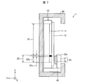
- FIG. 7 is a cross-sectional view illustrating a schematic configuration of the display device 1 according to the present modification.
- FIG. 5B the case where the support substrate 31 covers the entire surface of the display unit 11 as shown in FIG. 1B has been described as an example.
- the present embodiment is not limited to this, and as shown in FIG. 7, when the display device 1 is viewed from the observer side, the support substrate 31 exposes the first display unit 21 (first display).
- the display unit 21 may be configured to have a size that exposes at least a part of the first display unit 21 and covers the second display unit 22 (for example, a size that covers only the second display unit 22).
- the manufacturing cost can be reduced compared to the first embodiment.
- an area that is not covered with the support substrate 31 does not require an observer to observe an image through the support substrate 31. You can get quality.
- FIG. 8 is a cross-sectional view showing a schematic configuration of the display device 1 according to the present embodiment.
- the display device 1 includes the display device 1 at the boundary with the first display unit 21 in the second display unit 22 of the display module 10 along the boundary.
- a black matrix 23 (light shielding member) serving as a light shielding region when viewed from the observer side is disposed.
- a black region is formed along the boundary portion with the first display portion 21 in the second display portion 22 of the display module 10.
- a light shielding region 22a is formed as a partition.
- the second display unit 22 is, for example, a 16: 1 area having an aspect ratio of 16: 1.
- a black area 22a composed of a black matrix 32 and a display area 22b which is a content display area are included. Is provided.
- the black matrix 23 is a line width that can be observed as a black region 22a (light-shielding region) when the display device 1 is viewed from the observer side, more specifically, the first display unit 21 and the second display unit 22. It is only necessary to have a size capable of separating the display area 22b.
- the black region 22a has a line width of one line or more.
- the line width (length in the Z-axis direction) of the black region 22a is preferably 119 lines at the maximum, and more preferably 10 lines or less.
- the black region 22a is formed along the boundary portion of the second display portion 22 of the display module 10 with the first display portion 21 along the boundary portion.
- the black region 22a is realized by the black matrix 23, so that the synthesis process of the third image data required in the third embodiment is not required, and it is physically performed regardless of the video. A misalignment margin can be secured. Further, at this time, by using the black matrix 23 as the light shielding member, no new parts or new processes are required to provide the partition, and the display device 1 provided with the partition without significant design change. Can be manufactured. Therefore, an increase in manufacturing cost can be suppressed.
- the black matrix 32 is not limited as long as possible.
- a reflective member made of a metal material may be provided as a light shielding member that forms a light shielding region.
- the black matrix 32 is preferably provided on the second display unit 22 side in order not to prevent the display of the main content video, but may be provided on the first display unit 21 side. Also in this embodiment, the black matrix 32 that is a partition may be provided at the boundary between the first display unit 21 and the second display unit 22 and the other display unit in at least one of the display units. It may be provided.
- FIGS. 9 (a) and 9 (b) Still another embodiment of the present invention will be described below with reference to FIGS. 9 (a) and 9 (b).
- differences from the first to fourth embodiments will be mainly described.
- Components having the same functions as those used in the first to fourth embodiments are denoted by the same reference numerals. The description is omitted.
- the display device 1 when the display device 1 is viewed from the observer side outside the display panel, the first display unit 21 and the display area 22b in the second display unit 22 are visually separated.
- a case where a general partition is provided will be described as an example.
- FIG. 9A is a front view showing a schematic configuration of a main part of the display module 10 in the display device 1 according to the present embodiment
- FIG. 9B is a diagram of the display device 1 according to the present embodiment. It is sectional drawing which shows schematic structure of the principal part.
- the display module 10 is provided on the viewer-side surface of the support substrate 31 (that is, the surface opposite to the surface on which the transmissive mirror unit 32 is formed).
- a structure 33 is formed as a partition along the boundary between the first display unit 21 and the second display unit 22.
- the structure 33 may be, for example, printed or vapor-deposited paint on the support substrate 31, or may be a rod-shaped structure made of resin, metal, or the like attached to the support substrate 31.
- the structure 33 may be a black type such as a black name, but is not limited to this, and it is preferable to select a color and a material that match the overall design of the display device 1.
- the structure 33 may be a metal bar having a metallic luster combined with the housing design, and the surface may be patterned. Moreover, it is not limited to a single color.
- the width of the structure 33 in the Z-axis direction is the same as the width of the partition in the third and fourth embodiments in the Z-axis direction so that the first display portion 21 and the display area 22b in the second display portion 22 can be separated.
- it is formed in a size that can absorb the positional deviation from the image end (the boundary line between the first display unit 21 and the second display unit 22) due to thermal expansion or contraction.
- the width of the structure 33 in the Z-axis direction is equal to or more than one line.
- the width of the structure 33 in the Z-axis direction is preferably a maximum of 119 lines, and more preferably 10 lines or less.
- the structure 33 is located along the boundary portion with the first display portion 21 in the second display portion 22 of the display module 10.
- the transmissive mirror unit 32 is displayed on the first display unit 21.
- the influence can be prevented, and the disturbance of the image at the boundary can be eliminated.
- the structure 33 can secure a positional deviation margin.
- the partition that separates the first display unit 21 and the second display unit 22 is realized by the structure 33, so that a positional deviation margin can be secured physically and easily regardless of the image. be able to.
- the existing display module 10 can be used as it is, and no design change is required in manufacturing the display module 10. For this reason, introduction is easy.
- the structure 33 is described as an example in which the structure 33 is provided at the boundary between the second display unit 22 of the display module 10 and the first display unit 21. Also in this embodiment, in order not to disturb the display of the main content video, it is preferable to provide the structure 33 serving as a partition on the second display unit 22 side, but it may be provided on the first display unit 21 side. Moreover, you may form the structure 33 ranging over both display parts so that the boundary part of the 1st display part 21 and the 2nd display part 22 may be covered.
- the structure 33 covers the upper end 32 a of the transmissive mirror portion 32 on the surface of the support substrate 31 opposite to the surface on which the transmissive mirror portion 32 is formed. May be formed.
- the surface of a protective plate or the like (not shown) provided on the surface of the polarizing plate 12 or the display module 10 along the boundary between the first display unit 21 and the second display unit 22 of the display module 10.
- the structure 33 may be provided.
- the transmissive mirror unit 32 and the second display unit 22 be provided as close as possible to each other. Since it can arrange
- FIG. 10A is a front view showing a schematic configuration of a main part of the display module 10 in the display device 1 according to the present embodiment
- FIG. 10B is a diagram of the display device 1 according to the present embodiment. It is sectional drawing which shows schematic structure of the principal part.
- the display module 10 has a light emitting portion (on the end surface 10a side) closer to the positioning member 40 than the second display portion 22 in the display module 10.
- the backlight 13 is provided as a lighting device or a light source.
- a transmissive display type display panel using a backlight is used as the display panel in the display module 10 according to the present embodiment.
- the display panel is not particularly limited as long as it is a transmissive display side panel using a backlight.
- a transmissive display type liquid crystal panel or the like can be used as the display panel.
- the backlight 13 includes, for example, an LED (light emitting diode) as the light emitter 14.
- the light emitter 14 is not limited to this, and may be, for example, a fluorescent tube or a laser light source.
- a guide 15 is provided on the polarizing plate 12 side of the backlight 13. Thereby, the light from the backlight 13 is irradiated in parallel to the substrate surface of the display panel in the direction of the display unit 11 from the edge of the backlight 13 and passes through the display unit 11 (color filter) to the outside (of the display unit 11). The light emitted from the backlight 13 is not directly emitted to the outside through the polarizing plate 12.
- the present embodiment by providing the backlight 13 serving as a heat source on the positioning member 40 side of the second display unit 22 in the display module 10 as described above, the first display unit 21 located at a position away from the heat source. Can be suppressed.
- the transmissive mirror unit 32 is provided opposite to the second display unit 22 on the backlight 13 side, display unevenness due to light leakage due to thermal distortion occurs on the second display unit 22 side. However, it is possible to make display unevenness difficult to see with the transmissive mirror portion 32.
- (Modification) 10A and 10B illustrate the case where the backlight 13 is provided on the lower end side of the display module 10 as an example, but the present embodiment is not limited to this.
- the backlight 13 is provided on the positioning member 40 side of the second display unit 22, in other words, on the end surface 10 a side of the first display unit 21 and the second display unit 22 on the second display unit 22 side in the display module 10. It only has to be done.
- the arrangement of the backlight 13 is also changed according to the arrangement of the first display unit 21 and the second display unit 22. Is done.
- the display device 1 includes a display module 10 having a display surface provided with first and second display units (first display unit 21 and second display unit 22), and the second module.
- a translucent member (optical member 30) having a transmissive mirror part 32 facing the display unit (second display unit 22) and covering the second display unit, and fixed to the display module 10 and the positioning member 40
- the display module 10 and the translucent member are respectively end surfaces 10a and 30a on the second display portion side of the first and second display portions (that is, the end faces 10a and 30a).
- the end surfaces 10a and 30a) on the transmissive mirror portion 32 side are in contact with the positioning member 40, while the end surfaces 10b and 30b on the first display portion side are free ends that are not in contact with anything. ing.
- the said display module 10 and the said translucent member make the said 2nd display part the said translucent mirror part 32 face the said 2nd display part in the said translucent member.
- the positioning member 40 into contact with the positioning member 40 in a state of being covered, the translucent member provided with the transmissive mirror portion 32 is displayed on the display module 10 without directly attaching the transmissive mirror to the polarizing plate. It can be provided very close to the surface. For this reason, the parallax-less effect equivalent to the case where a transmissive mirror is directly attached to a polarizing plate can be obtained.
- the position shift of the boundary line of a 1st display part and a 2nd display part and a transparent mirror end can be suppressed rather than sticking a transmissive mirror directly to a polarizing plate.
- the said display module 10 and the said translucent member can be easily positioned by making the said display module 10 and the said translucent member contact the positioning member 40.
- the said transparent mirror part with respect to a said 2nd display part is arrange
- the positional deviation of 32 can be suppressed, and the processing dimensional accuracy and assembly accuracy of the display device 1 can be improved.
- the said display module 10 and the said translucent member since the end surface 10b * 30b by the side of the said 1st display part is a free end, the said by thermal expansion and thermal contraction It is possible to prevent the displacement variation (positional deviation) of the end surfaces 10b and 30b on the first display unit side from being applied to the second display unit side (the transmissive mirror unit 32 side).
- the position shift of the said 2nd display part and the said transmissive mirror part 32 is suppressed, and the alignment precision of the said 2nd display part and the said transmissive mirror part 32 is improved. Can be improved.
- the display device 1 is the first display unit (first display unit 21) and the second display unit in the display module 10 when viewed from the observer side in the first mode.
- a partition for example, third image data displayed in the black region 22a) that divides the first display unit and the second display unit along the boundary unit with the boundary unit with the (second display unit 22).
- An image (video) such as a black bar based on the above, a light shielding member such as a black matrix 23 forming a light shielding region, a structure 33, or the like may be provided.
- the partition along the boundary portion at the boundary portion between the first display portion and the second display portion for example, due to thermal expansion or thermal contraction, the permeability is increased. Even if a positional deviation occurs between the mirror unit 32 and the second display unit, it is possible to eliminate image disturbance at the boundary. Moreover, according to said structure, even if there exists a slight position shift at the time of alignment of the transmissive mirror part 32, this position shift can be hidden (absorbed) by the said partition. Therefore, a positional deviation margin can be secured by the partition.
- the partition is an optical partition based on an image
- the display module 10 displays on the first display unit (first display unit 21).
- a combining unit (display control unit 100) for combining the third image data to be displayed as the partition may be provided at a boundary portion (for example, the black region 22a) with the other display unit.
- the boundary part of said 1st display part and said 2nd display part (Boundary part with the other display part in at least one display part among said 1st and 2nd display parts) ),
- the third image data that separates the first display portion and the second display portion can be displayed as the partition. Therefore, the position deviation margin can be secured by the partition.
- the partition may be a physical partition.
- the positional deviation margin can be physically secured regardless of the images (videos) displayed on the first and second display units.
- the display device 1 according to aspect 5 of the present invention is the display apparatus 1 according to aspect 4, in which the first display unit (first display unit 21) and the second display unit (second display unit 22) in the display module 10 are provided.
- a light shielding region by a light shielding member (for example, black matrix 23) functioning as the partition may be provided at the boundary portion (for example, black region 22a).
- a light shielding region by the light shielding member can be provided at a boundary portion between the first display unit and the second display unit in the display module 10. Therefore, according to the above configuration, the positional deviation margin is physically increased by the light shielding member (light shielding region by the light shielding member) regardless of the images (videos) displayed on the first and second display units. Can be secured.
- the light shielding member may be a black matrix 23.
- the display apparatus 1 provided with the said partition can be manufactured without a big design change. Therefore, an increase in manufacturing cost can be suppressed.
- the display device 1 according to the seventh aspect of the present invention is the first display section (first first) in the display module 10 or the translucent member (optical member 30) when viewed from the observer side in the fourth aspect.
- a structure 33 that functions as the partition may be provided along a boundary between the display unit 21) and the second display unit (second display unit 22).
- the positional deviation margin can be secured physically and easily by the structure 33 regardless of the images (videos) displayed on the first and second display units.
- the existing display module 10 can be used as it is, and a design change in manufacturing the display module 10 is not required. For this reason, introduction is easy.
- the display module 10 has a light source closer to the positioning member 40 than the second display part (second display part 22). (Backlight 13) may be provided.
- the said 1st display part in the position away from the heat source is provided. Distortion can be suppressed. Further, since the transmissive mirror portion 32 is provided facing the second display portion on the light source side, display unevenness due to light leakage due to thermal distortion occurs in the second display portion. Even so, it is possible to make display unevenness difficult to see due to the transmissive mirror portion 32.
- the display device 1 according to the ninth aspect of the present invention is the display device 1 according to any one of the first to eighth aspects, wherein the translucent member (the optical member 30) is the first and second when viewed from the observer side.
- a support substrate 31 having a size covering the display units (the first display unit 21 and the second display unit 22) may be provided, and the transmissive mirror unit 32 may be formed on a part of the support substrate 31.
- the display surface of the display module 10 can be protected by the support substrate.
- the display device 1 according to the tenth aspect of the present invention is the display device 1 according to any one of the first to eighth aspects, wherein the translucent member (optical member 30) is the first display section (when viewed from the observer side).
- the support substrate 31 has a size that exposes at least part of the first display unit 21) and covers the second display unit (second display unit 22).
- the transmissive mirror unit 32 includes the support substrate 31. It may be formed in at least a part of.
- the manufacturing cost can be suppressed as compared with the above aspect 9.
- the region that is not covered with the support substrate 31 does not require the observer to observe the image through the support substrate 31, so that high display quality can be obtained.
- the transmissive mirror unit 32 is at least in a non-display region on the positioning member 40 side with respect to the second display unit (second display unit 22). It is preferable that at least a part of the non-display area that is partially covered and covered with the transmissive mirror part 32 is exposed from the casing.
- the non-display area (frame area) closer to the positioning member 40 than the second display section can be mirror-displayed by the transmissive mirror section 32, the second display section And a non-display area (frame area) closer to the positioning member 40 than the second display portion can be integrated.
- the positioning member 40 may be a part of the casing 50.
- the positioning member 40 since it is not necessary to provide the positioning member 40 separately from the housing 50, the number of parts can be reduced and the manufacturing cost can be suppressed.
- the area (frame area) of the bezel portion on the lower side of the housing (front housing portion 51) viewed from the observer side can be reduced. For this reason, the freedom degree of design of the frame part (front side housing
- the display device according to the present invention can be suitably used for an electronic device such as a TV or a portable terminal in which a transmissive mirror portion is provided so as to face a part of the display surface of the display module.
Landscapes
- Physics & Mathematics (AREA)
- General Physics & Mathematics (AREA)
- Optics & Photonics (AREA)
- Nonlinear Science (AREA)
- Mathematical Physics (AREA)
- Chemical & Material Sciences (AREA)
- Crystallography & Structural Chemistry (AREA)
- Spectroscopy & Molecular Physics (AREA)
- Devices For Indicating Variable Information By Combining Individual Elements (AREA)
- Engineering & Computer Science (AREA)
- Microelectronics & Electronic Packaging (AREA)
Abstract
表示装置(1)は、第1表示部(21)および第2表示部(22)が設けられた表示モジュール(10)と、第2表示部(22)に面して透過性ミラー部(32)を有する光学部材(30)と、位置決め部材(40)とを備えている。表示モジュール(10)および光学部材(30)は、端面(10a・30a)が位置決め部材(40)に接触している一方、端面(10b・30b)が自由端となっている。
Description
本発明は、表示モジュールと、透過性ミラー部を有する透光性部材とを備えた表示装置に関するものである。
近年、透過性ミラー部を備え、該透過性ミラー部の後方に表示面が設けられた表示装置、あるいはそのような表示装置を備えた電子機器が多数提案されている。透過性ミラー部は、光の透過が可能な反射または散乱素材からなり、一部の光を透過し、一部の光を反射または散乱する。
例えば特許文献1には、筐体の前面部に、透過性ミラー部としてハーフミラーを形成した鏡面部を組み付けた携帯型電子機器が開示されている。該携帯型電子機器におけるハーフミラーの背後には、ハーフミラーに密着させて、あるいはハーフミラーとの間に若干隙間を設けて、液晶ディスプレイを含む表示モジュールを収容するホルダが設けられている。
特許文献2には、ブラインドシートが、表示モジュールにおけるディスプレイあるいは該ディスプレイを内側に収容した透明パネルの一部または全部に貼着された端末装置が開示されている。上記ブラインドシートには、支持体となる透光性フィルムの一面の一部または全部に、透過性ミラー部としてハーフミラーが形成されている。
特許文献3には、液晶パネルを備えた表示部と、該表示部上に積層されたマジックミラー部とを備えた表示体が開示されている。上記液晶パネルには、状態表示領域と内容表示領域とが設けられており、マジックミラー部における上記状態表示領域上に位置する部位には、透明な透過領域が形成されている。また、マジックミラー部における上記内容表示領域上に位置する部位には、透過性ミラー部として、反射膜を有する半透過領域が形成されている。
しかしながら、上記従来の表示装置は、表示画面に表示する映像に対する透過性ミラー部の位置精度が低いという問題点を有している。
特許文献1では、上述したように、表示モジュールが、ハーフミラーに密着させて、あるいはハーフミラーとの間に若干隙間を設けて配置されている。しかしながら、例えば特許文献1のように筐体に透過性ミラーが設けられた光学部材(以下、「透過性ミラー」と称する)を組み付ける場合、透過性ミラーがディスプレイ表面から離れていると、視差による映像の位置ズレが発生する。
視差による映像の位置ズレを抑制するためには、ディスプレイ表面にできるだけ近接して透過性ミラーを設けることが望ましい。
そこで、例えば特許文献2のように、ディスプレイ表面に透過性ミラーを貼着することが考えられる。
しかしながら、液晶ディスプレイ等のディスプレイの表面には、一般的に偏光板が設けられている。このため、例えば特許文献1のようにディスプレイ表面に透過性ミラーを貼り合わせる場合、偏光板に透過性ミラーが貼着されることになる。
しかしながら、偏光板には、一般的に、熱による変形や撓み等が発生し易い樹脂系の材料が用いられている。このため、偏光板と透過性ミラーとの貼合わせ精度は低い。
また、偏光板に透過性ミラーを正確に貼れたとしても、ディスプレイ本体を構成するパネル部と、偏光板に貼合わされた透過性ミラーとの位置決めは非常に困難である。また、上述したように偏光板は熱による変形や撓み等が発生し易いことから、パネル部と偏光板とを位置合わせし、製品化した後でも、偏光板の熱変形により両者の位置関係にはズレが生じ易い。
同様に、特許文献3のように液晶パネルを備えた表示部と、マジックミラー部との位置決めや、特許文献1のように筐体の前面部に設けられたハーフミラーと、筐体内の空間部に収容された表示モジュールを収容するホルダとの位置決めも困難である。
しかも、特許文献3のように、液晶パネルに2つの表示部(表示領域)を設け、マジックミラー部におけるそれぞれの表示部上に位置する部位に透過領域と半透過領域とを設ける場合、表示体を組み立てる際の公差や熱膨張収縮等により、透過領域と半透過領域との境界線と各表示領域との位置ズレが発生し易い。特に、一方の領域(例えば半透過領域)を介して表示される画像(映像)の一部が他方の領域(例えば透過領域)を介して表示される場合、コンテンツ配信側の意図と異なる表示がなされ、ユーザに混乱をきたすおそれがある。このため、特許文献3に記載の表示体は、テレビ等のように公共性の高いコンテンツを表示するのに適していない。
本発明は、上記問題点に鑑みなされたものであり、表示モジュールにおける2つの表示部のうち一方の表示部と、該表示部に対応して配された透過性ミラーとの位置ズレを抑制することができる表示装置を提供することを目的とする。
上記の課題を解決するために、本発明の一態様に係る表示装置は、第1および第2の表示部が設けられた表示面を有する表示モジュールと、上記第2の表示部に面して上記第2の表示部を覆う透過性ミラー部を有する透光性部材と、上記表示モジュールと上記透光性部材とを位置合わせする位置決め部材と、を備え、上記表示モジュールおよび上記透光性部材は、それぞれ、上記第1および第2の表示部のうち第2の表示部側の端面で上記位置決め部材に接触している一方、上記第1の表示部側の端面が、どこにも接触していない自由端となっている。
本発明の一態様によれば、偏光板に透過性ミラーを直接貼らなくても、透過性ミラー部が設けられた透光性部材を表示モジュールの表示面に極めて近接して設けることができる。このため、偏光板に透過性ミラーを直接貼る場合と同等の視差レス効果を得ることができる。また、偏光板に透過性ミラーを直接貼るよりも、第1の表示部と第2の表示部との境界線と透過性ミラー端との位置ズレを抑えることができる。
また、本発明の一態様によれば、上記表示モジュールと上記透光性部材との位置決めを容易に行うことができる。
さらに、変位量が少ない位置決め部材側に、上記第2の表示部並びに上記透過性ミラー部を配置することになるので、上記第2の表示部に対する上記透過性ミラー部の位置ズレを抑制し、上記表示装置の加工寸法精度および組立精度を向上させることができる。
また、上記表示モジュールおよび上記透光性部材における、上記第1の表示部側の端面が自由端となっていることで、熱膨張や熱収縮による上記第1の表示部側の端面の変位バラツキ(位置ズレ)が上記第2の表示部側(透過性ミラー部側)に加わることを防止することができる。
このため、本発明の一態様によれば、上記第2の表示部と上記透過性ミラー部との位置ズレを抑制し、上記第2の表示部と上記透過性ミラー部との位置合わせ精度を向上させることができる。
以下、本発明の実施の形態について、詳細に説明する。
〔実施形態1〕
以下、本発明の実施の形態について、図1(a)・(b)および図2に基づいて説明すれば、以下のとおりである。
以下、本発明の実施の形態について、図1(a)・(b)および図2に基づいて説明すれば、以下のとおりである。
(表示装置1の概略構成)
図1の(a)は、本実施形態に係る表示装置1の概略構成を示す正面図であり、図1の(b)は、図1の(a)に示す表示装置1のA-A線矢視断面図である。
図1の(a)は、本実施形態に係る表示装置1の概略構成を示す正面図であり、図1の(b)は、図1の(a)に示す表示装置1のA-A線矢視断面図である。
図1の(a)・(b)に示すように、表示装置1は、表示モジュール10、光学部材30、位置決め部材40(位置決め機構)、および筺体50を備えている。表示装置1は、透過表示領域と半透過表示領域とを兼ね備えた表示装置である。
なお、以下、図1の(a)・(b)において、Z軸方向を表示モジュール10の行方向(上方向)とし、Z軸に垂直な水平方向の2軸方向をX軸方向およびY軸方向とし、そのうちX軸方向を表示モジュール10の列方向として説明する。
(光学部材30)
光学部材30は、透光性を有する支持基板31の少なくとも一部に透過性ミラー部32が設けられた透光性部材である。本実施形態では、図1の(a)・(b)に示すように、支持基板31の一部に透過性ミラー部32が設けられている。
光学部材30は、透光性を有する支持基板31の少なくとも一部に透過性ミラー部32が設けられた透光性部材である。本実施形態では、図1の(a)・(b)に示すように、支持基板31の一部に透過性ミラー部32が設けられている。
支持基板31には、ガラス、アクリル等の透明性の高い基板が用いられる。一方、透過性ミラー部32は、光の透過が可能な反射または散乱素材からなり、一部の光を透過し、一部の光を反射または散乱する。
透過性ミラー部32には、例えば、アルミニウム等の金属を蒸着してなるハーフミラー(半透明鏡)等を使用することができる。透過性ミラー部32は、接着層等を備えた、支持基板31とは別の支持体に金属を蒸着してなる例えばシート状の透過性ミラー部材を支持基板31に貼り付けることによって形成されていてもよく、支持基板31に金属を直接蒸着することによって形成されていてもよい。
光学部材30は、表示モジュール10の表示面側に、表示モジュール10に対向して設けられている。また、透過性ミラー部32は、支持基板31における表示モジュール10側に、第2表示部22に面して設けられている。
(表示モジュール10)
表示モジュール10は、表示部11を備えるとともに、表示部11の表示面側に設けられた偏光板12(表側偏光板)を備えている。また、表示モジュール10は、図示はしないが、表示部11の表示面とは反対側に設けられた偏光板(裏側偏光板)や、バックライトが設けられたバックライトフレーム、表示部11に画像(映像)を表示させるための回路基板等、表示部11に画像(映像)を表示させるために必要な構成を備えている。
表示モジュール10は、表示部11を備えるとともに、表示部11の表示面側に設けられた偏光板12(表側偏光板)を備えている。また、表示モジュール10は、図示はしないが、表示部11の表示面とは反対側に設けられた偏光板(裏側偏光板)や、バックライトが設けられたバックライトフレーム、表示部11に画像(映像)を表示させるための回路基板等、表示部11に画像(映像)を表示させるために必要な構成を備えている。
表示モジュール10の表示部11には、例えば液晶パネルが使用される。但し、表示部11に使用される表示パネルは、液晶パネルに限定されるものではなく、有機EL(エレクトロルミネッセンス)パネル、無機ELパネル、プラズマパネル等であってもよい。したがって、表側偏光板、裏側偏光板、バックライト等は必須ではない。
なお、これら表示パネルの構成は、従来の表示装置に使用される一般的な表示パネルと同じであるため、その説明並びに細部の図示を省略する。また、バックライト等についても、従来の表示装置に使用されるものと同じであるため、その説明並びに細部の図示を省略する。
表示モジュール10は、同一面(同一表示面)に第1表示部21(第1の表示部、メイン領域)と第2表示部22(第2の表示部、サブ領域)とを備えている。すなわち、表示部11の表示面は、第1表示部21と第2表示部22とに分割されている。
第1表示部21には、例えば第1の映像信号に基づく第1の映像が表示される。第2表示部22には、第1表示部21とは異なる第2の映像信号に基づく第2の映像が表示される。第1の映像は、例えばメインコンテンツ映像であり、第2の映像は、例えばサブコンテンツ映像である。
第1表示部21のアスペクト比は、例えば16:9であり、第1表示部21ではフルHD(High Definition)の映像を表示することができる。また、第2表示部22のアスペクト比は16:1である。
第1表示部21(例えば16:9領域)は透過表示領域であり、第2表示部22(例えば16:1領域)は半透過表示領域である。表示モジュール10における第2表示部22の表示面側には、光学部材30における透過性ミラー部32が配置されている。
図1の(b)に示すように、位置決め部材40の表面から光学部材30における透過性ミラー部32の遠端(上端部32a)までのZ軸方向の高さは、位置決め部材40の表面から第2表示部22の遠端(上端部、第1表示部21との境界線)までのZ軸方向の高さとほぼ同じ位置(厳密には、第1表示部21と第2表示部22との境界線が透過性ミラー部32の上端部32aより僅かに上方)になるように設定されている。
また、図1の(a)・(b)に示すように、支持基板31は、表示装置1を観察者側から見たときに(つまり、表示モジュール10および光学部材30を位置決め部材40に固定した状態で、観察者側から見て)、第1表示部21および第2表示部22を覆う大きさに形成されている。また、透過性ミラー部32は、表示装置1を観察者側から見たときに、第2表示部22を覆う大きさに形成されている。つまり、支持基板31は、第1表示部21が16:9領域であり、第2表示部22が例えば16:1領域である場合に、16:10領域を覆う大きさに形成されている。
第1表示部21に表示される映像は、支持基板31における透過性ミラー部32が設けられていない領域越しに確認することができる。第2表示部22に表示される映像は、透過性ミラー部32越しに確認することができる。
(位置決め部材40)
位置決め部材40は、表示モジュール10と光学部材30との位置合わせに使用される。位置決め部材40は、図1の(b)に示すように、表示モジュール10および光学部材30における、上記第2表示部22側の端面10a・30a(言い換えれば、半透過領域側である、光学部材30における透過性ミラー部32形成側の端面10a・30a)に接して設けられている。なお、光学部材30における、上記第2表示部22側の端面30aは、具体的には、支持基板31における、上記第2表示部22側の端面31aを示す。
位置決め部材40は、表示モジュール10と光学部材30との位置合わせに使用される。位置決め部材40は、図1の(b)に示すように、表示モジュール10および光学部材30における、上記第2表示部22側の端面10a・30a(言い換えれば、半透過領域側である、光学部材30における透過性ミラー部32形成側の端面10a・30a)に接して設けられている。なお、光学部材30における、上記第2表示部22側の端面30aは、具体的には、支持基板31における、上記第2表示部22側の端面31aを示す。
本実施形態にかかる表示モジュール10および光学部材30は、それぞれ、上記第1表示部21および第2表示部22のうち上記第2表示部22側の端面10a・30aで位置決め部材40に固定されている一方、上記第2表示部22側の端面10a・30aとは反対側(対向側)の端面10b・30b(すなわち、第1表示部21側の端面10b・30b)が、どこにも接触していない(つまり、どこにも固定されていない)自由端となっている。
このため、表示モジュール10および光学部材30における上記第1表示部21側の端面10b・30bと筐体50との間にはそれぞれ隙間が設けられている。表示モジュール10および光学部材30は、それぞれ、上記第1表示部21側の端面10b・30b以外の部分で、筐体50および位置決め部材40に支持されている。
上記位置決め部材40としては、例えば樹脂系や金属系の材料からなる板状部材が使用される。樹脂系の材料からなる板状部材としては、例えば、プラスチック板が挙げられる。また、金属系の材料からなる板状部材としては、例えば、アルミニウムあるいは鉄等の金属からなる板が挙げられる。
なお、表示モジュール10および光学部材30を位置決め部材40に固定する方法としては、特に限定されるものではなく、例えば、接着、ネジ留め、嵌合等の公知の各種固定方法を用いることができる。表示モジュール10および光学部材30を位置決め部材40に嵌合させる場合、位置決め部材40に図示しない溝部(嵌合溝)を設け、該溝部に表示モジュール10および光学部材30を嵌め込めばよい。また、位置決め部材40に溝部を設ける代わりに、位置決め部材40に、ストッパとしての複数の突起部を設けても構わない。この場合、突起部に、表示モジュール10および光学部材30を付勢する付勢力を持たせることで、表示モジュール10および光学部材30の位置決め部材40への着脱および固定を容易に行うことができる。
(筺体50)
表示モジュール10、光学部材30、位置決め部材40は、筐体50内に収容されている。筐体50は、例えば表示モジュール10の表示面側に設けられた表側筐体部51(第1の筐体部)と、表示モジュール10の背面側(観察者側とは反対側)に設けられた裏側筐体部52(第2の筐体部)とで構成されている。
表示モジュール10、光学部材30、位置決め部材40は、筐体50内に収容されている。筐体50は、例えば表示モジュール10の表示面側に設けられた表側筐体部51(第1の筐体部)と、表示モジュール10の背面側(観察者側とは反対側)に設けられた裏側筐体部52(第2の筐体部)とで構成されている。
表側筐体部51には、表示装置1で表示される映像を透過させる開口部53が設けられている。表側筐体部51および裏側筐体部52は、例えば、何れか一方が、断面L字状に形成されており、表側筐体部51と裏側筐体部52とで、表示モジュール10、光学部材30、位置決め部材40を挟み込むように挟持している。
なお、筺体50とこれら表示モジュール10、光学部材30、位置決め部材40との間には僅かな隙間が設けられており、これら表示モジュール10、光学部材30、および位置決め部材40は、筐体50に設けられた図示しない支持部により、これら表示モジュール10、光学部材30、および位置決め部材40が倒れないように、筐体50によって部分的に支持(例えば筐体50に点接触)されている。
(表示モジュール10と透過性ミラー部32との間の隙間)
視差による映像の位置ズレを抑制するためには、透過性ミラー部32は、表示モジュール10の第2表示部22にできるだけ近接して設けられていることが望ましい。このためには、透過性ミラー部32は、前述したように、支持基板31における表示モジュール10側に、第2表示部22に面して設けられていることが望ましく、表示モジュール10と光学部材30とは、図1の(b)に示すY軸方向にできるだけ近接して設けられていることが望ましい。
視差による映像の位置ズレを抑制するためには、透過性ミラー部32は、表示モジュール10の第2表示部22にできるだけ近接して設けられていることが望ましい。このためには、透過性ミラー部32は、前述したように、支持基板31における表示モジュール10側に、第2表示部22に面して設けられていることが望ましく、表示モジュール10と光学部材30とは、図1の(b)に示すY軸方向にできるだけ近接して設けられていることが望ましい。
表示モジュール10における表示パネルの基板あるいは光学部材30における支持基板31には、例えばガラスが好適に使用される。ガラスの実使用想定の熱膨張あるいは熱収縮は、Z軸方向に1ライン(TV映像等の16:9フルHD領域で0.1%(1ライン/1080ライン)、例えば30型クラスのTV(テレビジョン)で約0.3mm)(±0.15mm)程度である。したがって、上下視野角20°以内程度で視聴(観察)した際に、熱膨張あるいは熱収縮による位置ズレを1画素以内で抑えるためには、tan20°から、表示モジュール10と光学部材30との間の隙間は、0.5mm程度に抑えることが好ましい。
したがって、表示モジュール10と透過性ミラー部32との間の隙間は、例えば30型の表示装置1で0.5mm以下であることが好ましく、例えば60型の表示装置1で1mm以下(0.5mm×60型/30型)であることが好ましい。
表示モジュール10と透過性ミラー部32との間の隙間を例えば上記範囲内とすることで、偏光板12に透過性ミラーを直接貼る場合と同等の視差レス効果を得ることができる。
(効果)
前述したように、表示装置に透過性ミラーが設けられた光学部材を組み付ける場合、透過性ミラーがディスプレイ表面から離れていると、視差による映像の位置ズレが発生する。このため、透過性ミラーは、ディスプレイ表面にできるだけ近付けて設けることが望ましい。しかしながら、偏光板と透過性ミラーとの貼合わせ精度が低いことから、透過性ミラーを偏光板に直接貼ることは望ましくない。
前述したように、表示装置に透過性ミラーが設けられた光学部材を組み付ける場合、透過性ミラーがディスプレイ表面から離れていると、視差による映像の位置ズレが発生する。このため、透過性ミラーは、ディスプレイ表面にできるだけ近付けて設けることが望ましい。しかしながら、偏光板と透過性ミラーとの貼合わせ精度が低いことから、透過性ミラーを偏光板に直接貼ることは望ましくない。
そこで、本実施形態では、上述したように、支持基板31に、第2表示部22に面して透過性ミラー部32を設けるとともに、表示モジュール10および支持基板31における上記透過性ミラー部32側の端面10a・30aを位置決め部材40に固定した。
本実施形態によれば、上記の構成とすることで、偏光板12に透過性ミラーを直接貼らなくても、透過性ミラー部32が設けられた光学部材30を表示モジュール10の表示面(ディスプレイ表面)に極めて近接して設けることができる。これにより、偏光板12に透過性ミラーを直接貼る場合と同等の視差レス効果を得ることができる。
しかも、上記の構成によれば、偏光板12に透過性ミラーを直接貼るよりも、第1表示部21と第2表示部22との間の映像端(言い換えれば、第1表示部21と第2表示部22との境界線)と透過性ミラー端との位置ズレを抑えることができる。なお、視差による上記位置ズレを抑制するためには、表示モジュール10と光学部材30との間の隙間を前述した範囲内とすることが望ましい。
また、本実施形態によれば、表示モジュール10と、透過性ミラー部32が設けられた光学部材30とを位置決め部材40により固定することで、表示モジュール10と光学部材30との位置決めを容易に行うことができる。
さらに、本実施形態では、表示モジュール10および支持基板31における上記透過性ミラー部32側の端面10a・30aを位置決め部材40に固定することにより、変位量が少ない位置決め部材40側に、位置ズレを抑制したい透過性ミラー部32を配置している。このため、本実施形態によれば、第2表示部22に対する透過性ミラー部32の位置ズレを抑制し、表示モジュール10および支持基板31の加工寸法精度および組立精度を向上させることができる。
また、本実施形態によれば、表示モジュール10および支持基板31における上記透過性ミラー部32側とは反対側の第1表示部21側の端面10b・30bが自由端となっている。
このため、表示モジュール10および支持基板31における第1表示部21側の端面10b・30bと筐体50との間の隙間により、表示モジュール10および支持基板31の熱膨張や熱収縮、あるいは、位置決め部材40の熱膨張や熱収縮による、表示モジュール10および支持基板31の第1表示部21側の端面31bのZ方向の変位(位置ズレ)を吸収することができる。このため、これらの変位バラツキ(位置ズレ)が透過性ミラー部32側に加わることを防止することができる。
また、上述したように表示モジュール10および支持基板31の第1表示部21側の変位(位置ズレ)を吸収することができるので、熱による表示モジュール10および支持基板31の変形を抑制することができる。したがって、表示モジュール10や支持基板31が変形して筐体50から外れたりすることがない。
このため、本実施形態によれば、第2表示部22と透過性ミラー部32との位置ズレを抑制し、第2表示部22と透過性ミラー部32との位置合わせ精度を向上させることができる。
したがって、本実施形態に係る表示装置1は、一方の表示領域(例えば第2表示部22)を介して表示される画像(映像)の一部が他方の表示領域(例えば第1表示部21)を介して表示されることがなく、コンテンツ配信側の意図と異なる表示がなされることがない。このため、本実施形態に係る表示装置1は、テレビ等のように公共性の高いコンテンツを表示する表示装置として好適に用いることができる。
(変形例)
図2は、本変形例に係る表示装置1の概略構成を示す断面図である。なお、図2は、図1の(a)に示す表示装置1のA-A線矢視断面図に相当する。
図2は、本変形例に係る表示装置1の概略構成を示す断面図である。なお、図2は、図1の(a)に示す表示装置1のA-A線矢視断面図に相当する。
図1の(a)・(b)では、表示装置1が、筺体50内に、筐体50とは別に位置決め部材40を備えている場合を例に挙げて図示した。
しかしながら、本実施形態は、これに限定されるものではなく、図2に示すように、筺体50が位置決め部材40を兼ねていても構わない。言い換えれば、位置決め部材40は、筺体50の一部であっても構わない。
すなわち本変形例にかかる表示装置1は、表示モジュール10、光学部材30、位置決め部材兼筐体として用いられる筺体50を備えている。
本変形例にかかる筐体50は、その内表面の一部、つまり、表示モジュール10および光学部材30を内部に収容したときに、表示モジュール10および光学部材30の第2表示部22側の端面10a・30aと対向する面50a(図2に示す例では筐体50の内壁底面)が、平らになるように形成されている。
これにより、本変形例にかかる筐体50は、上記面50aにおいて、表示モジュール10および光学部材30に、点接触ではなく、面接触する。
このため、本実施形態では、表示モジュール10および光学部材30は、それぞれの端面10a・30aが、上記面50aに接して配されており、該面50aに固定されている。なお、本変形例でも、筐体50における、表示モジュール10および光学部材30の端面10b・30bとの対向面は、表示モジュール10および光学部材30に接触しないように形成されており、上記端面10b・30bは、どこにも固定されていない自由端となっている。
本変形例によれば、筐体50とは別に位置決め部材40を設ける必要がないため、部品点数を削減することができ、製造コストを抑えることができる。
また、本変形例によれば、表側筐体部51における、筐体50の面50aから表示部11側に向かって突出する部分の長さを、図1に示す表示装置1よりも小さくすることができる。このため、本変形例によれば、観察者側から見た表側筐体部51の下辺側のベゼル部分の面積(額縁面積)を縮小させることができる。このため、表側筐体部51のデザインの自由度を向上させることができる。
(その他の変形例)
なお、本実施形態では、第1表示部21が、アスペクト比が16:9の領域(16:9領域)であり第2表示部22が、アスペクト比が16:1の領域(16:1領域)である場合を例に挙げて説明した。しかしながら、第1表示部21および第2表示部22のアスペクト比はこれに限定されるものではなく、所望の大きさに形成することができる。
なお、本実施形態では、第1表示部21が、アスペクト比が16:9の領域(16:9領域)であり第2表示部22が、アスペクト比が16:1の領域(16:1領域)である場合を例に挙げて説明した。しかしながら、第1表示部21および第2表示部22のアスペクト比はこれに限定されるものではなく、所望の大きさに形成することができる。
また、本実施形態では、第2表示部22が第1表示部21の下側に設けられており、位置決め部材40が、筐体50の内壁底面側に設けられているか、あるいは、筐体50の内壁底面に表示モジュール10および光学部材30が固定される場合を例に挙げて説明した。
しかしながら、第1表示部21と第2表示部22との位置関係はこれに限定されるものではなく、例えば、第2表示部22が第1表示部21の上側あるいは横方向に設けられた構成を有していてもよい。
何れの場合でも、表示モジュール10および光学部材30は、第1表示部21および第2表示部22のうち、半透過表示領域である第2表示部22側(つまり、透過性ミラー部32側)で位置決め部材40に固定されていればよい。したがって、位置決め部材40の配置は、表示モジュール10および光学部材30における透過性ミラー部32側に配置されるように、第1表示部21および第2表示部22の配置に応じて適宜決定すればよい。
また、本実施形態では、表示モジュール10および光学部材30が位置決め部材40に固定されている場合を例に挙げて説明したが、表示モジュール10および光学部材30は、表示モジュール10および光学部材30が位置決め部材40側で位置決めされるように、それぞれの端面10a・30aが位置決め部材40に接触していればよく、必ずしも固定されている必要はない。
例えば、位置決め部材40に、表示モジュール10および光学部材30を嵌め込むための溝部を設けるに際し、該溝部に、表示モジュール10および光学部材30が微小に動くように遊びが設けられていても構わない。この場合、例えば、位置決め部材40に、平面視で表示モジュール10および光学部材30の端面10a・30aを合わせた面積よりも一回り大きい面積を有する溝部を設け、該溝部内に表示モジュール10および光学部材30を収容してもよい。また、位置決め部材40に、平面視で表示モジュール10および光学部材30の端面10a・30aよりも一回り大きい溝部をそれぞれ設け、それぞれの溝部内に表示モジュール10および光学部材30をそれぞれ収容してもよい。
また、表示モジュール10および光学部材30が位置決め部材40に接触した状態で表示モジュール10および光学部材30が筐体50で挟み込まれることで、表示モジュール10および光学部材30が、移動しないか、もしくは、移動が制限されていてもよい。
表示装置1の使用形態にもよるが、表示モジュール10および光学部材30は、上下左右方向それぞれに対し、位置ズレしないか、もしくは、位置ズレし難いことが望ましい。
〔実施形態2〕
本発明の他の実施形態について、図3~図4に基づいて説明すれば、以下のとおりである。なお、本実施の形態では、主に、実施の形態1との相違点について説明するものとし、実施の形態1で用いた構成要素と同一の機能を有する構成要素には同一の符号を付し、その説明を省略する。
本発明の他の実施形態について、図3~図4に基づいて説明すれば、以下のとおりである。なお、本実施の形態では、主に、実施の形態1との相違点について説明するものとし、実施の形態1で用いた構成要素と同一の機能を有する構成要素には同一の符号を付し、その説明を省略する。
(表示装置1の概略構成)
図3は、本実施形態に係る表示装置1の概略構成を示す断面図である。
図3は、本実施形態に係る表示装置1の概略構成を示す断面図である。
本実施形態に係る表示装置1は、図3に示すように、表示装置1を観察者側から見たときに、支持基板31が、第1表示部21を露出(第1表示部21の少なくとも一部を露出)し、第2表示部22を覆う大きさ(例えば第2表示部22のみを覆う大きさ)に形成されており、これにより、第1表示部21が露出して設けられている点で、実施形態1と異なっている。
なお、本実施形態でも、透過性ミラー部32は、表示装置1を観察者側から見たときに、第2表示部22を覆う大きさに形成されている。
したがって、本実施形態では、第1表示部21に表示される映像は、支持基板31を介さずに直接確認することができる。また、第2表示部22に表示される映像は、透過性ミラー部32越しに確認することができる。
(効果)
本実施形態によれば、実施形態1に記載の効果に加え、支持基板31の高さが低いため、実施形態1と比べて製造コストを抑えることができるという効果を奏する。
本実施形態によれば、実施形態1に記載の効果に加え、支持基板31の高さが低いため、実施形態1と比べて製造コストを抑えることができるという効果を奏する。
また、第1表示部21において、支持基板31で覆われていない領域は、支持基板31を介して映像を観察する必要がないため、高い表示品位が得ることができるという効果を奏する。
一方、実施形態1のように表示装置1を観察者側から見たときに、支持基板31が、表示部11全面を覆っていることで、支持基板31により、表示部11の表面(表示モジュール10の表示面)を保護することができるという効果を奏する。
(変形例)
図4は、本変形例に係る表示装置1の概略構成を示す断面図である。
図4は、本変形例に係る表示装置1の概略構成を示す断面図である。
図3では、実施形態1同様、支持基板31における表示モジュール10との対向面の一部に透過性ミラー部32が設けられている場合を例に挙げて説明した。
本変形例にかかる表示装置1は、支持基板31における表示モジュール10との対向面全面に透過性ミラー部32が設けられている点および表側筐体部51の下辺額縁端(つまり、表側筐体部51における位置決め部材40側の開口端)が第2表示部22の下辺(下端)よりも下方(位置決め部材40側)にある点で、図3に示す表示装置1と異なっている。
なお、透過性ミラー部32は、接着層等を備えた、支持基板31とは別の支持体に金属を蒸着してなる例えばシート状の透過性ミラー部材を支持基板31に貼り付けることによって形成されていてもよく、支持基板31に金属を直接蒸着することによって形成されていてもよく、光学部材30全体が透過性ミラーであってもよい。
本変形例によれば、支持基板31の高さが低いため、実施形態1と比べて製造コストを抑えることができる。また、本変形例によれば、第2表示部22よりも下方(位置決め部材40側)の非表示領域(額縁領域)を透過性ミラー部32によりミラー表示させることが可能であるため、第2表示部22と第2表示部22よりも下方(位置決め部材40側)の非表示領域(額縁領域)とを一体化させたデザインとすることができる。
なお、図4では、支持基板31における表示モジュール10との対向面全面に透過性ミラー部32が設けられている場合を例に挙げて説明したが、上記透過性ミラー部32が、第2表示部22よりも位置決め部材40側の非表示領域の少なくとも一部を覆っているとともに、透過性ミラー部32で覆われた非表示領域の少なくとも一部が筐体50から露出していることで、上述した効果と同様の効果を得ることができる。
〔実施形態3〕
本発明のさらに他の実施形態について、図5の(a)・(b)~図7に基づいて説明すれば、以下のとおりである。なお、本実施の形態では、主に、実施形態1、2との相違点について説明するものとし、実施形態1、2で用いた構成要素と同一の機能を有する構成要素には同一の符号を付し、その説明を省略する。
本発明のさらに他の実施形態について、図5の(a)・(b)~図7に基づいて説明すれば、以下のとおりである。なお、本実施の形態では、主に、実施形態1、2との相違点について説明するものとし、実施形態1、2で用いた構成要素と同一の機能を有する構成要素には同一の符号を付し、その説明を省略する。
(表示装置1の概略構成)
図5の(a)は、本実施形態に係る表示装置1の要部の概略構成を示す正面図であり、図5の(b)は、本実施形態に係る表示装置1の要部の概略構成を示す断面図である。なお、図5の(a)では、図示の便宜上、光学部材30の図示を省略するとともに、筐体50を一点鎖線にて示している。
図5の(a)は、本実施形態に係る表示装置1の要部の概略構成を示す正面図であり、図5の(b)は、本実施形態に係る表示装置1の要部の概略構成を示す断面図である。なお、図5の(a)では、図示の便宜上、光学部材30の図示を省略するとともに、筐体50を一点鎖線にて示している。
本実施形態に係る表示モジュール10は、図5の(a)・(b)に示すように、第1表示部21と第2表示部22との境界部、例えば第2表示部22における第1表示部21との境界部に、該境界部に沿って、例えば所定の幅の黒色映像(黒色ライン、以下、「黒バー」と記す)を表示する点で、実施形態1における図1の(a)・(b)に示す表示装置1と異なっている。
すなわち、本実施形態にかかる表示モジュール10は、図5の(a)に示すように、表示装置1を観察者側から見たときに表示モジュール10の第2表示部22における第1表示部21との境界部に、該境界部に沿って黒バーからなる黒領域22aが、光学的な仕切りとして形成されている。
具体的には、図5の(b)に示すように、第2表示部22を分割して黒バーを表示している。黒バーは、第2表示部22における第1表示部21側に表示され、第2表示部22の残りの領域、すなわち、黒バーを表示する黒領域22a(第1表示領域)以外の表示領域22b(第2表示領域)に、本来、第2表示部22に表示すべき映像(画像データ)が表示される。
第1表示部21は、例えばアスペクト比が16:9の16:9領域である。また、第2表示部22は、例えばアスペクト比が16:1の16:1領域であり、16:1領域内には、黒バーを表示する黒領域22aと、16:1領域内におけるコンテンツ表示領域である表示領域22bとが設けられている。
なお、本実施形態でも、実施形態1、2と同様に、位置決め部材40の表面から光学部材30における透過性ミラー部32の遠端(上端部32a)までのZ軸方向の高さは、位置決め部材40の表面から第2表示部22の遠端(上端部、第1表示部21との境界線)までのZ軸方向の高さとほぼ同じ位置になるように設定されている。
但し、第1表示部21には、例えばフルHDのメインコンテンツ映像が表示される。このため、第1表示部21に表示される画像データが透過性ミラー部32越しに表示されることは望ましくない。このため、第1表示部21と第2表示部22との境界部には、熱膨張あるいは熱収縮による位置ズレにより第1表示部21に透過性ミラー端(透過性ミラー部32の上端部32a)が重ならないための位置ズレマージンが設けられていることが望ましい。
したがって、黒バーのライン幅(Z軸方向の長さ)は、第2表示部22と透過性ミラー部32との位置合わせ時のズレを吸収できるように設定することが好ましく、透過性ミラー部32の上端部32aは、黒領域22a内、好適には、Z軸方向における黒領域22aの中央部分に位置するように設けられていることが望ましい。
前述したように、ガラスの実使用想定の熱膨張あるいは熱収縮は、1ライン程度である。したがって、具体的には、表示部11のパネルの1ライン(1920ピクセル)以上の幅を黒バー(黒領域22a)の幅とする。
なお、このとき、TV映像等の、アスペクト比が16:9のフルHD領域(1080ライン)を確保するには、上述したように第2表示部22に黒バーを表示する必要がある。このとき、例えば、WUXGA(Wide Ultra Extended Graphics Array、1920ピクセル×1200ライン)における、コンテンツの表示に必要なライン数を差し引いた残り120ライン内で黒バーを表示すると考えれば、黒バー(黒領域22a)のライン幅(Z軸方向の長さ)は、最大で119ラインとすることが望ましく、10ライン以下(120ラインの1割以下)とすることがより望ましい。
(黒バーの表示)
次に、表示モジュール10に黒バーを表示する方法について説明する。
次に、表示モジュール10に黒バーを表示する方法について説明する。
以下では、黒バーを、第1画像データ、第2画像データとは別の第3画像データとして取得し、第1画像データ、第2画像データ、第3画像データを合成して、図5の(a)・(b)に示すように、表示モジュール10に合成画像を表示する場合を例に挙げて説明する。
図6は、本実施形態に係る表示モジュール10の制御部の概略構成の一例を示すブロック図である。
表示モジュール10に合成画像を表示するために、表示モジュール10は、図6に示すように、表示制御部100(合成部、制御部)および記憶部130を備えているとともに、図6に点線で示す画像生成部140を備えている。
表示制御部100は、例えば、第1画像データと、第2画像データと、黒バー(第3画像データ)とを合成した合成画像を表示部11に表示させる。
ここで、第1画像データは、チューナあるいはインターネット等のネットワーク経由で取得した、アスペクト比が16:9の画像データである。また、第2画像データは、インターネット等のネットワーク経由で取得するか、あるいは、装置内部の画像生成部140で生成した、アスペクト比が16:1の画像データである。また、黒バーは、一例として、装置内部の画像生成部140で生成した第3画像データである。
表示制御部100は、第1画像データ、第2画像データ、および第3画像データを合成した合成処理を行うSoC(システム・オン・チップ)100と、合成処理された画像データの表示部11への出力タイミングを調整するタイミングコントローラ120とを含んでいる。なお、SoCは、電子システムの構成要素を単一のチップの中に集積したものである。
本実施形態では、SoC110は、同期化部111と画像合成部112とを含み、取得した第1画像データ、第2画像データ、および第3画像データを、同期化部111にて同期を合わせて、画像合成部112にて一つの画像に合成する。
画像合成部112は、同期のとれた第1画像データ、第2画像データ、および第3画像データを、記憶部130に予め記憶された表示位置情報に応じた表示位置にそれぞれ表示されるように画像合成を行う。
画像合成部112にて合成された画像データは、タイミングコントローラ120に出力され、該タイミングコントローラ120にて表示部11への表示のタイミングが調整される。
このように合成処理された画像は、図5の(a)・(b)に示すように、表示モジュール10のアスペクト比が16:9の第1画像データが第1表示部21に表示され、例えばアスペクト比が16:1の第2画像データと、第3画像データとしての黒バーとが、第2表示部22に表示される。
なお、上述した例では、黒バーを、第1画像データおよび第2画像データとは別に生成される第3画像データとしたが、第2画像データに含めるようにしてもよい。この場合、黒バー付きの第2画像データを、インターネット等のネットワーク経由で取得するか。装置内部の画像生成部140で生成するようにすればよい。なお、黒バー付きの第2画像データを、インターネット等のネットワーク経由で取得する場合、画像生成部140を省略することができる。
(効果)
本実施形態によれば、実施形態1に記載の効果に加え、第1表示部21と第2表示部22との境界部に、該境界部に沿って、黒領域22aとなる黒バーを表示させることで、例えば熱膨張あるいは熱収縮等により透過性ミラー部32と第2表示部22との位置ズレが生じたとしても、透過性ミラー部32が第1表示部21における表示に影響を与えることを防止することができ、上記境界部での映像の乱れを無くすことができる。また、上記の構成によれば、透過性ミラー部32の位置合わせの際に若干の位置ズレがあったとしても、該位置ズレを上記黒バーによる黒領域22aによって隠す(吸収する)ことができる。したがって、上記黒バーによる黒領域22aにより、位置ズレマージンを確保することができる。
本実施形態によれば、実施形態1に記載の効果に加え、第1表示部21と第2表示部22との境界部に、該境界部に沿って、黒領域22aとなる黒バーを表示させることで、例えば熱膨張あるいは熱収縮等により透過性ミラー部32と第2表示部22との位置ズレが生じたとしても、透過性ミラー部32が第1表示部21における表示に影響を与えることを防止することができ、上記境界部での映像の乱れを無くすことができる。また、上記の構成によれば、透過性ミラー部32の位置合わせの際に若干の位置ズレがあったとしても、該位置ズレを上記黒バーによる黒領域22aによって隠す(吸収する)ことができる。したがって、上記黒バーによる黒領域22aにより、位置ズレマージンを確保することができる。
(仕切りの変形例)
なお、本実施形態では、第3画像データとして黒バーを表示させる場合を例に挙げて説明したが、上記第3画像データとしては、第1表示部21と第2表示部22における表示領域22bとを分けることができればよく、黒色以外の色の画像データであってもよい。
なお、本実施形態では、第3画像データとして黒バーを表示させる場合を例に挙げて説明したが、上記第3画像データとしては、第1表示部21と第2表示部22における表示領域22bとを分けることができればよく、黒色以外の色の画像データであってもよい。
すなわち、上記仕切りとしては、黒色以外の色の映像であってもよい。但し、透過性ミラー部32の有無の境界を認識し難くできることから、上記仕切りとしては、単色の映像であることが好ましく、黒色系の色の映像であることが好ましい。
なお、上述したようにメインコンテンツ映像の表示を妨げないためには、仕切りは、第2表示部22側に設ける(表示させる)ことが好ましいが、第1表示部21側に設けてもよい。上記仕切りは、第1表示部21および第2表示部22のうち少なくとも一方の表示部における他方の表示部との境界部に設ければよく、両表示部に設けても構わない。
(光学部材30の変形例)
図7は、本変形例に係る表示装置1の概略構成を示す断面図である。
図7は、本変形例に係る表示装置1の概略構成を示す断面図である。
図5の(b)では、図1の(b)に示すように、支持基板31が、表示部11全面を覆っている場合を例に挙げて説明した。
しかしながら、本実施形態は、これに限定されるものではなく、図7に示すように、表示装置1を観察者側から見たときに、支持基板31が、第1表示部21を露出(第1表示部21の少なくとも一部を露出)し、第2表示部22を覆う大きさ(例えば第2表示部22のみを覆う大きさ)に形成されている構成を有していてもよい。
本変形例によれば、本実施形態に記載の効果に加えて、実施形態2同様、支持基板31の高さが低いため、実施形態1と比べて製造コストを抑えることができるという効果を奏する。
また、本変形例でも、実施形態2同様、第1表示部21において、支持基板31で覆われていない領域は、観察者が支持基板31を介して映像を観察する必要がないため、高い表示品位を得ることができる。
(その他の変形例)
なお、本実施形態では、図5の(a)に示す技術的手段と実施形態2における図3に開示された技術的手段との組み合わせについて図示することで、特に実施形態2における図3との相違点について図示した。しかしながら、本実施形態と、異なる実施形態に開示された技術的手段との組み合わせは、上記変形例にのみ限定されるものではない。
なお、本実施形態では、図5の(a)に示す技術的手段と実施形態2における図3に開示された技術的手段との組み合わせについて図示することで、特に実施形態2における図3との相違点について図示した。しかしながら、本実施形態と、異なる実施形態に開示された技術的手段との組み合わせは、上記変形例にのみ限定されるものではない。
前述したように、本実施形態では、主に、実施形態1、2との相違点について説明しており、特に言及はしていないが、本実施形態においても、実施形態1、2と同様に、上述した変形例のみならず、実施形態1、2に記載の他の変形例についても同様に適用できることは、言うまでもない。なお、後述する実施形態についても同様である。
〔実施形態4〕
本発明のさらに他の実施形態について、図8に基づいて説明すれば、以下のとおりである。本実施の形態では、主に、実施形態1~3との相違点について説明するものとし、実施形態1~3で用いた構成要素と同一の機能を有する構成要素には同一の符号を付し、その説明を省略する。
本発明のさらに他の実施形態について、図8に基づいて説明すれば、以下のとおりである。本実施の形態では、主に、実施形態1~3との相違点について説明するものとし、実施形態1~3で用いた構成要素と同一の機能を有する構成要素には同一の符号を付し、その説明を省略する。
(表示装置1の概略構成)
実施形態3では、表示モジュール10の第2表示部22における第1表示部21との境界部に、該境界部に沿って光学的な仕切りを設ける場合を例に挙げて説明した。これに対し、本実施形態では、表示モジュール10の第2表示部22における第1表示部21との境界部に、該境界部に沿って物理的な仕切りを設ける場合を例に挙げて説明する。
実施形態3では、表示モジュール10の第2表示部22における第1表示部21との境界部に、該境界部に沿って光学的な仕切りを設ける場合を例に挙げて説明した。これに対し、本実施形態では、表示モジュール10の第2表示部22における第1表示部21との境界部に、該境界部に沿って物理的な仕切りを設ける場合を例に挙げて説明する。
図8は、本実施形態に係る表示装置1の概略構成を示す断面図である。
本実施形態にかかる表示装置1には、図8に示すように、表示モジュール10の第2表示部22における第1表示部21との境界部に、該境界部に沿って、表示装置1を観察者側から見たきに遮光領域となるブラックマトリクス23(遮光部材)を配置している。
これにより、本実施形態では、表示装置1を観察者側から見たきに、表示モジュール10の第2表示部22における第1表示部21との境界部に、該境界部に沿って、黒領域22aとなる遮光領域が、仕切りとして形成されている。
第2表示部22は、例えばアスペクト比が16:1の16:1領域であり、該16:1領域内には、ブラックマトリクス32からなる黒領域22aと、コンテンツ表示領域である表示領域22bとが設けられている。
ブラックマトリクス23は、表示装置1を観察者側から見たときに黒領域22a(遮光領域)として観察することができるライン幅、より具体的には、第1表示部21と第2表示部22における表示領域22bとを分けることができる大きさを有していればよい。
これにより、熱膨張あるいは熱収縮による映像端(第1表示部21と第2表示部22との境界線)と透過ミラー端との位置ズレによる映像の乱れを抑制することができるが、ブラックマトリクス23は、熱膨張あるいは熱収縮による映像端と透過ミラー端との位置ズレを吸収することができるライン幅に形成されていることが好ましい。したがって、本実施形態でも、黒領域22aは、1ライン分以上のライン幅を有していることが好ましい。
また、本実施形態でも、黒領域22aのライン幅(Z軸方向の長さ)は、最大で119ラインとすることが望ましく、10ライン以下とすることがより望ましい。
(効果)
本実施形態でも、表示装置1を観察者側から見たときに、表示モジュール10の第2表示部22における第1表示部21との境界部に、該境界部に沿って、黒領域22aが設けられていることで、例えば熱膨張あるいは熱収縮等により透過性ミラー部32と第2表示部22との位置ズレが生じたとしても、透過性ミラー部32が第1表示部21における表示に影響を与えることを防止することができ、上記境界部での映像の乱れを無くすことができる。また、上記の構成によれば、透過性ミラー部32の位置合わせの際に若干の位置ズレがあったとしても、該位置ズレを上記黒領域22aによって隠す(吸収する)ことができる。したがって、上記黒領域22aにより、位置ズレマージンを確保することができる。
本実施形態でも、表示装置1を観察者側から見たときに、表示モジュール10の第2表示部22における第1表示部21との境界部に、該境界部に沿って、黒領域22aが設けられていることで、例えば熱膨張あるいは熱収縮等により透過性ミラー部32と第2表示部22との位置ズレが生じたとしても、透過性ミラー部32が第1表示部21における表示に影響を与えることを防止することができ、上記境界部での映像の乱れを無くすことができる。また、上記の構成によれば、透過性ミラー部32の位置合わせの際に若干の位置ズレがあったとしても、該位置ズレを上記黒領域22aによって隠す(吸収する)ことができる。したがって、上記黒領域22aにより、位置ズレマージンを確保することができる。
また、本実施形態によれば、黒領域22aをブラックマトリクス23により実現することで、実施形態3で必要とされる第3画像データの合成処理を必要とせず、映像に拘らず、物理的に位置ズレマージンを確保することができる。また、このとき、上記遮光部材としてブラックマトリクス23を用いることで、上記仕切りを設けるために新たな部品や新たな工程を必要とせず、大幅な設計変更無しに上記仕切りが設けられた表示装置1を製造することができる。したがって、製造コストの上昇を抑えることができる。
(変形例)
なお、本実施形態では、黒領域22aとなる遮光領域をブラックマトリクス23により形成する場合を例に挙げて説明したが、表示装置1を観察者側から見たときに遮光領域として観察することができるものであれば、ブラックマトリクス32に限定されるものではない。例えば、ブラックマトリクス32に代えて、金属材料からなる反射部材が、遮光領域を形成する遮光部材として設けられていても構わない。
なお、本実施形態では、黒領域22aとなる遮光領域をブラックマトリクス23により形成する場合を例に挙げて説明したが、表示装置1を観察者側から見たときに遮光領域として観察することができるものであれば、ブラックマトリクス32に限定されるものではない。例えば、ブラックマトリクス32に代えて、金属材料からなる反射部材が、遮光領域を形成する遮光部材として設けられていても構わない。
また、本実施形態でも、メインコンテンツ映像の表示を妨げないためには、ブラックマトリクス32は、第2表示部22側に設けることが好ましいが、第1表示部21側に設けても構わない。本実施形態でも、仕切りであるブラックマトリクス32は、第1表示部21および第2表示部22のうち少なくとも一方の表示部における他方の表示部との境界部に設ければよく、両表示部に設けても構わない。
〔実施形態5〕
本発明のさらに他の実施形態について、図9の(a)・(b)に基づいて説明すれば、以下のとおりである。本実施の形態では、主に、実施形態1~4との相違点について説明するものとし、実施形態1~4で用いた構成要素と同一の機能を有する構成要素には同一の符号を付し、その説明を省略する。
本発明のさらに他の実施形態について、図9の(a)・(b)に基づいて説明すれば、以下のとおりである。本実施の形態では、主に、実施形態1~4との相違点について説明するものとし、実施形態1~4で用いた構成要素と同一の機能を有する構成要素には同一の符号を付し、その説明を省略する。
実施形態4では、表示モジュール10における表示パネル内に、第1表示部21と第2表示部22における表示領域22bとを物理的に分ける、物理的な仕切りを設ける場合を例に挙げて説明した。
これに対し、本実施形態では、表示パネル外に、表示装置1を観察者側から見たときに、第1表示部21と第2表示部22における表示領域22bとを視覚的に分ける、物理的な仕切りを設ける場合を例に挙げて説明する。
(表示装置1の概略構成)
図9の(a)は、本実施形態に係る表示装置1における表示モジュール10の要部の概略構成を示す正面図であり、図9の(b)は、本実施形態に係る表示装置1の要部の概略構成を示す断面図である。
図9の(a)は、本実施形態に係る表示装置1における表示モジュール10の要部の概略構成を示す正面図であり、図9の(b)は、本実施形態に係る表示装置1の要部の概略構成を示す断面図である。
図9の(a)・(b)に示す表示装置1は、支持基板31における観察者側の面(すなわち、透過性ミラー部32の形成面とは反対側の面)に、表示モジュール10の第1表示部21と第2表示部22との境界部に沿って、仕切りとして、構造物33が形成されている。
構造物33は、支持基板31に例えば塗料を印刷または蒸着したものであってもよく、支持基板31に取り付けられた樹脂や金属等からなる棒状の構造物であってもよい。
なお、構造物33は、黒色名等の黒色系であってもよいが、これに限らず、表示装置1の全体のデザインに合った色および素材が選択されることが好ましい。例えば、構造物33は、筐体デザインと合わせた金属光沢を有する金属バーであってもよく、表面に模様が付されていてもよい。また、単色に限定されるものではない。
構造物33のZ軸方向の幅は、実施形態3、4における仕切りのZ軸方向の幅と同じく、第1表示部21と第2表示部22における表示領域22bとを分けることができる大きさを有していればよいが、熱膨張あるいは熱収縮による映像端(第1表示部21と第2表示部22との境界線)との位置ズレを吸収することができる大きさに形成されていることが好ましい。したがって、本実施形態でも、構造物33のZ軸方向の幅は、1ライン分以上であることが好ましい。
また、本実施形態でも、構造物33のZ軸方向の幅は、最大で119ライン分とすることが望ましく、10ライン分以下とすることがより望ましい。
(効果)
本実施形態でも、表示装置1を観察者側から見たときに、表示モジュール10の第2表示部22における第1表示部21との境界部に、該境界部に沿って、構造物33が設けられていることで、例えば熱膨張あるいは熱収縮等により透過性ミラー部32と第2表示部22との位置ズレが生じたとしても、透過性ミラー部32が第1表示部21における表示に影響を与えることを防止することができ、上記境界部での映像の乱れを無くすことができる。また、上記の構成によれば、透過性ミラー部32の位置合わせの際に若干の位置ズレがあったとしても、該位置ズレを上記構造物33によって隠す(吸収する)ことができる。したがって、上記構造物33により、位置ズレマージンを確保することができる。
本実施形態でも、表示装置1を観察者側から見たときに、表示モジュール10の第2表示部22における第1表示部21との境界部に、該境界部に沿って、構造物33が設けられていることで、例えば熱膨張あるいは熱収縮等により透過性ミラー部32と第2表示部22との位置ズレが生じたとしても、透過性ミラー部32が第1表示部21における表示に影響を与えることを防止することができ、上記境界部での映像の乱れを無くすことができる。また、上記の構成によれば、透過性ミラー部32の位置合わせの際に若干の位置ズレがあったとしても、該位置ズレを上記構造物33によって隠す(吸収する)ことができる。したがって、上記構造物33により、位置ズレマージンを確保することができる。
また、本実施形態によれば、第1表示部21と第2表示部22とを分ける仕切りを構造物33により実現することで、映像に拘らず、物理的かつ簡単に位置ズレマージンを確保することができる。
特に、上記構造物33を光学部材30に設けることで、既存の表示モジュール10をそのまま用いることができ、表示モジュール10の製造における設計変更を必要としない。このため、導入が容易である。
(変形例)
なお、図9の(a)・(b)では、構造物33を、表示モジュール10の第2表示部22における第1表示部21との境界部に設けた場合を例に挙げて説明した。本実施形態でも、メインコンテンツ映像の表示を妨げないためには、仕切りとなる構造物33を第2表示部22側に設けることが好ましいが、第1表示部21側に設けても構わない。また、第1表示部21と第2表示部22との境界部を覆うように両表示部に跨がって構造物33を形成してもよい。
なお、図9の(a)・(b)では、構造物33を、表示モジュール10の第2表示部22における第1表示部21との境界部に設けた場合を例に挙げて説明した。本実施形態でも、メインコンテンツ映像の表示を妨げないためには、仕切りとなる構造物33を第2表示部22側に設けることが好ましいが、第1表示部21側に設けても構わない。また、第1表示部21と第2表示部22との境界部を覆うように両表示部に跨がって構造物33を形成してもよい。
また、図9の(a)・(b)では、支持基板31における透過性ミラー部32の形成面とは反対側の面に、透過性ミラー部32の上端部32aを覆うように構造物33を形成しても構わない。
また、図示はしないが、表示モジュール10の第1表示部21と第2表示部22との境界部に沿って、偏光板12あるいは表示モジュール10の表面に設けられた図示しない保護板等の表面に構造物33が設けられていてもよい。
但し、視差による位置ズレを防止するためには、透過性ミラー部32と第2表示部22とはできるだけ近接して設けられていることが、透過性ミラー部32と第2表示部22とをより近接して配置することができることから、好ましい。
〔実施形態6〕
本発明のさらに他の実施形態について、図10の(a)・(b)に基づいて説明すれば、以下のとおりである。本実施の形態では、主に、実施形態1~5との相違点について説明するものとし、実施形態1~5で用いた構成要素と同一の機能を有する構成要素には同一の符号を付し、その説明を省略する。
本発明のさらに他の実施形態について、図10の(a)・(b)に基づいて説明すれば、以下のとおりである。本実施の形態では、主に、実施形態1~5との相違点について説明するものとし、実施形態1~5で用いた構成要素と同一の機能を有する構成要素には同一の符号を付し、その説明を省略する。
(表示装置1の概略構成)
図10の(a)は、本実施形態に係る表示装置1における表示モジュール10の要部の概略構成を示す正面図であり、図10の(b)は、本実施形態に係る表示装置1の要部の概略構成を示す断面図である。
図10の(a)は、本実施形態に係る表示装置1における表示モジュール10の要部の概略構成を示す正面図であり、図10の(b)は、本実施形態に係る表示装置1の要部の概略構成を示す断面図である。
本実施形態に係る表示モジュール10は、図10の(a)・(b)に示すように、表示モジュール10における第2表示部22よりも位置決め部材40側(端面10a側)に、発光部(照明装置、光源)としてバックライト13が設けられた構成を有している。
このため、本実施形態にかる表示モジュール10における表示パネルには、バックライトを使用する透過表示型の表示パネルが用いられる。なお該表示パネルとしては、バックライトを使用する透過表示側の表示パネルであれば、特に限定されるものではない。該表示パネルとしては、例えば、透過表示型の液晶パネル等を用いることができる。
バックライト13は、発光体14として例えばLED(発光ダイオード)を備えている。しかしながら、発光体14は、これに限定されるものではなく、例えば蛍光管やレーザ光源であってもよい。
バックライト13における偏光板12側にはガイド15が設けられている。これにより、バックライト13からの光は、該バックライト13のエッジから表示部11の方向に、表示パネルの基板面に平行に照射され、表示部11(カラーフィルタ)を通して外部(表示部11の正面側)に出射され、バックライト13からの光が直接偏光板12を通して外部に出射されることはない。
(効果)
本実施形態によれば、このように表示モジュール10における第2表示部22よりも位置決め部材40側に、熱源となるバックライト13を設けることで、熱源から離れた位置にある第1表示部21の歪みを抑制することができる。また、透過性ミラー部32がバックライト13側の第2表示部22に対向して設けられていることで、第2表示部22側で熱的歪みによる光漏れに起因する表示ムラが生じたとしても、透過性ミラー部32により表示ムラを見え難くすることができる。
本実施形態によれば、このように表示モジュール10における第2表示部22よりも位置決め部材40側に、熱源となるバックライト13を設けることで、熱源から離れた位置にある第1表示部21の歪みを抑制することができる。また、透過性ミラー部32がバックライト13側の第2表示部22に対向して設けられていることで、第2表示部22側で熱的歪みによる光漏れに起因する表示ムラが生じたとしても、透過性ミラー部32により表示ムラを見え難くすることができる。
(変形例)
なお、図10の(a)・(b)では、バックライト13を表示モジュール10の下端側に設けた場合を例に挙げて図示したが、本実施形態はこれに限定されるものではない。
なお、図10の(a)・(b)では、バックライト13を表示モジュール10の下端側に設けた場合を例に挙げて図示したが、本実施形態はこれに限定されるものではない。
バックライト13は、第2表示部22よりも位置決め部材40側、言い換えれば、表示モジュール10における、第1表示部21および第2表示部22のうち第2表示部22側の端面10a側に設けられていればよい。
したがって、例えば第2表示部22が第1表示部21の上側あるいは横方向に設けられている場合、第1表示部21および第2表示部22の配置に応じて、バックライト13の配置も変更される。
〔まとめ〕
本発明の態様1に係る表示装置1は、第1および第2の表示部(第1表示部21、第2表示部22)が設けられた表示面を有する表示モジュール10と、上記第2の表示部(第2表示部22)に面して上記第2の表示部を覆う透過性ミラー部32を有する透光性部材(光学部材30)と、上記表示モジュール10と位置決め部材40に固定とを位置合わせする位置決め部材40と、を備え、上記表示モジュール10および上記透光性部材は、それぞれ、上記第1および第2の表示部のうち第2の表示部側の端面10a・30a(つまり、上記透過性ミラー部32側の端面10a・30a)で上記位置決め部材40に接触している一方、上記第1の表示部側の端面10b・30bが、どこにも接触していない自由端となっている。
本発明の態様1に係る表示装置1は、第1および第2の表示部(第1表示部21、第2表示部22)が設けられた表示面を有する表示モジュール10と、上記第2の表示部(第2表示部22)に面して上記第2の表示部を覆う透過性ミラー部32を有する透光性部材(光学部材30)と、上記表示モジュール10と位置決め部材40に固定とを位置合わせする位置決め部材40と、を備え、上記表示モジュール10および上記透光性部材は、それぞれ、上記第1および第2の表示部のうち第2の表示部側の端面10a・30a(つまり、上記透過性ミラー部32側の端面10a・30a)で上記位置決め部材40に接触している一方、上記第1の表示部側の端面10b・30bが、どこにも接触していない自由端となっている。
上記の構成によれば、上記表示モジュール10と上記透光性部材とを、上記透光性部材に上記透過性ミラー部32が上記第2の表示部に面して上記第2の表示部を覆うように設けられた状態で上記位置決め部材40に接触させることで、偏光板に透過性ミラーを直接貼らなくても、透過性ミラー部32が設けられた透光性部材を表示モジュール10の表示面に極めて近接して設けることができる。このため、偏光板に透過性ミラーを直接貼る場合と同等の視差レス効果を得ることができる。
また、上記の構成によれば、偏光板に透過性ミラーを直接貼るよりも、第1の表示部と第2の表示部との境界線と透過性ミラー端との位置ズレを抑えることができる。
また、上記の構成によれば、上記表示モジュール10と上記透光性部材とを位置決め部材40に接触させることで、上記表示モジュール10と上記透光性部材との位置決めを容易に行うことができる。
さらに、上記の構成によれば、変位量が少ない位置決め部材40側に、上記第2の表示部並びに上記透過性ミラー部32を配置することで、上記第2の表示部に対する上記透過性ミラー部32の位置ズレを抑制し、上記表示装置1の加工寸法精度および組立精度を向上させることができる。
また、上記の構成によれば、上記表示モジュール10および上記透光性部材における、上記第1の表示部側の端面10b・30bが自由端となっていることで、熱膨張や熱収縮による上記第1の表示部側の端面10b・30bの変位バラツキ(位置ズレ)が上記第2の表示部側(透過性ミラー部32側)に加わることを防止することができる。
このため、上記の構成によれば、上記第2の表示部と上記透過性ミラー部32との位置ズレを抑制し、上記第2の表示部と上記透過性ミラー部32との位置合わせ精度を向上させることができる。
本発明の態様2に係る表示装置1は、上記態様1において、観察者側から見たときに、上記表示モジュール10における上記第1の表示部(第1表示部21)と第2の表示部(第2表示部22)との境界部に、該境界部に沿って、上記第1の表示部と第2の表示部とを分ける仕切り(例えば黒領域22aに表示される第3の画像データに基づく黒バー等の画像(映像)、遮光領域を形成するブラックマトリクス23等の遮光部材、構造物33等)が設けられていてもよい。
上記の構成によれば、上記第1の表示部と上記第2の表示部との境界部に、該境界部に沿って上記仕切りを設けることで、例えば熱膨張あるいは熱収縮等により上記透過性ミラー部32と上記第2の表示部との位置ズレが生じたとしても、上記境界部での映像の乱れを無くすことができる。また、上記の構成によれば、透過性ミラー部32の位置合わせの際に若干の位置ズレがあったとしても、該位置ズレを上記仕切りによって隠す(吸収する)ことができる。したがって、上記仕切りにより、位置ズレマージンを確保することができる。
本発明の態様3に係る表示装置1は、上記態様2において、上記仕切りは画像による光学的な仕切りであり、上記表示モジュール10は、上記第1の表示部(第1表示部21)に表示する第1の画像データおよび上記第2の表示部(第2表示部22における表示領域22b)に表示する第2の画像データに、上記第1および第2の表示部のうち少なくとも一方の表示部における他方の表示部との境界部(例えば黒領域22a)に上記仕切りとして表示する第3の画像データを合成する合成部(表示制御部100)を備えていてもよい。
上記の構成によれば、上記第1の表示部と上記第2の表示部との境界部(上記第1および第2の表示部のうち少なくとも一方の表示部における他方の表示部との境界部)に、上記仕切りとして、上記第1の表示部と第2の表示部とを分ける上記第3の画像データを表示させることができる。したがって、該仕切りにより、上記位置ズレマージンを確保することができる。
本発明の態様4に係る表示装置1は、上記態様2において、上記仕切りは物理的な仕切りであってもよい。
上記の構成によれは、上記第1および第2の表示部に表示させる画像(映像)に拘らず、物理的に上記位置ズレマージンを確保することができる。
本発明の態様5に係る表示装置1は、上記態様4において、上記表示モジュール10における上記第1の表示部(第1表示部21)と上記第2の表示部(第2表示部22)との境界部(例えば黒領域22a)に、上記仕切りとして機能する遮光部材(例えばブラックマトリクス23)による遮光領域が設けられていてもよい。
上記の構成によれば、上記表示モジュール10における上記第1の表示部と上記第2の表示部との境界部に、上記遮光部材による遮光領域を設けることができる。したがって、上記の構成によれば、上記遮光部材(該遮光部材による遮光領域)により、上記第1および第2の表示部に表示させる画像(映像)に拘らず、物理的に上記位置ズレマージンを確保することができる。
本発明の態様6に係る表示装置1は、上記態様5において、上記遮光部材はブラックマトリクス23であってもよい。
上記の構成によれば、上記表示モジュール10に上記仕切りを設けるために新たな部品や新たな工程を必要としない。このため、大幅な設計変更無しに上記仕切りが設けられた表示装置1を製造することができる。したがって、製造コストの上昇を抑えることができる。
本発明の態様7に係る表示装置1は、上記態様4において、観察者側から見たときに、上記表示モジュール10または透光性部材(光学部材30)における上記第1の表示部(第1表示部21)と上記第2の表示部(第2表示部22)との境界部に沿って、上記仕切りとして機能する構造物33が設けられていてもよい。
上記の構成によれば、上記構造物33により、上記第1および第2の表示部に表示させる画像(映像)に拘らず、物理的かつ簡単に上記位置ズレマージンを確保することができる。
特に、上記構造物33を上記透光性部材側に設けることで、既存の表示モジュール10をそのまま用いることができ、表示モジュール10の製造における設計変更を必要としない。このため、導入が容易である。
本発明の態様8に係る表示装置1は、上記態様1~7の何れかにおいて、上記表示モジュール10は、上記第2の表示部(第2表示部22)よりも上記位置決め部材40側に光源(バックライト13)を備えていてもよい。
上記の構成によれば、上記表示モジュール10における上記第2の表示部よりも上記位置決め部材40側に、熱源となる光源を設けることで、熱源から離れた位置にある上記第1の表示部の歪みを抑制することができる。また、上記透過性ミラー部32が上記光源側の上記第2の表示部に面して設けられていることで、上記第2の表示部で熱的歪みによる光漏れに起因する表示ムラが生じたとしても、上記透過性ミラー部32により表示ムラを見え難くすることができる。
本発明の態様9に係る表示装置1は、上記態様1~8の何れかにおいて、上記透光性部材(光学部材30)は、観察者側から見たときに、上記第1および第2の表示部(第1表示部21、第2表示部22)を覆う大きさの支持基板31を備え、上記透過性ミラー部32は、上記支持基板31の一部に形成されていてもよい。
上記の構成によれば、上記支持基板により上記表示モジュール10の表示面を保護することができる。
本発明の態様10に係る表示装置1は、上記態様1~8の何れかにおいて、上記透光性部材(光学部材30)は、観察者側から見たときに、上記第1の表示部(第1表示部21)の少なくとも一部を露出し、上記第2の表示部(第2表示部22)を覆う大きさの支持基板31を備え、上記透過性ミラー部32は、上記支持基板31の少なくとも一部に形成されていてもよい。
上記の構成によれば、上記態様9と比較して製造コストを抑えることができる。
また、上記第1の表示部において、支持基板31で覆われていない領域は、観察者が支持基板31を介して映像を観察する必要がないため、高い表示品位を得ることができる。
本発明の態様11に係る表示装置1は、上記態様10において、上記透過性ミラー部32は、上記第2の表示部(第2表示部22)よりも位置決め部材40側の非表示領域の少なくとも一部を覆っているとともに、上記透過性ミラー部32で覆われた非表示領域の少なくとも一部が筐体から露出していることが好ましい。
上記の構成によれば、上記第2の表示部よりも位置決め部材40側の非表示領域(額縁領域)を透過性ミラー部32によりミラー表示させることが可能であるため、上記第2の表示部と上記第2の表示部よりも位置決め部材40側の非表示領域(額縁領域)とを一体化させたデザインとすることができる。
本発明の態様12に係る表示装置1は、上記態様1~11の何れかにおいて、上記位置決め部材40が筺体50の一部であってもよい。
上記の構成によれば、筐体50とは別に位置決め部材40を設ける必要がないため、部品点数を削減することができ、製造コストを抑えることができる。
また、上記の構成によれば、観察者側から見た筐体(表側筐体部51)の下辺側のベゼル部分の面積(額縁面積)を縮小させることができる。このため、筐体の額縁部分(表側筐体部51)のデザインの自由度を向上させることができる。
本発明は上述した各実施形態に限定されるものではなく、請求項に示した範囲で種々の変更が可能であり、異なる実施形態にそれぞれ開示された技術的手段を適宜組み合わせて得られる実施形態についても本発明の技術的範囲に含まれる。さらに、各実施形態にそれぞれ開示された技術的手段を組み合わせることにより、新しい技術的特徴を形成することができる。
本発明にかかる表示装置は、表示モジュールにおける表示面の一部に対向して透過性ミラー部が設けられた、TVあるいは携帯端末等の電子機器に好適に用いることができる。
1 表示装置
10 表示モジュール
10a 端面
11 表示部
12 偏光板
13 バックライト(光源)
14 発光体
15 ガイド
21 第1表示部
22 第2の表示部
22a 黒領域
22b 表示領域
23 ブラックマトリクス(遮光部材、仕切り)
30 光学部材(透光性部材)
30a 端面
31 支持基板
31a 端面
31b 端面
32 ブラックマトリクス(仕切り)
32 透過性ミラー部
32a 上端部
33 構造物(仕切り)
40 位置決め部材
50 筐体
50a 面
51 表側筐体部
52 裏側筐体部
53 開口部
100 表示制御部
111 同期化部
112 画像合成部
120 タイミングコントローラ
130 記憶部
140 画像生成部
10 表示モジュール
10a 端面
11 表示部
12 偏光板
13 バックライト(光源)
14 発光体
15 ガイド
21 第1表示部
22 第2の表示部
22a 黒領域
22b 表示領域
23 ブラックマトリクス(遮光部材、仕切り)
30 光学部材(透光性部材)
30a 端面
31 支持基板
31a 端面
31b 端面
32 ブラックマトリクス(仕切り)
32 透過性ミラー部
32a 上端部
33 構造物(仕切り)
40 位置決め部材
50 筐体
50a 面
51 表側筐体部
52 裏側筐体部
53 開口部
100 表示制御部
111 同期化部
112 画像合成部
120 タイミングコントローラ
130 記憶部
140 画像生成部
Claims (11)
- 第1および第2の表示部が設けられた表示面を有する表示モジュールと、
上記第2の表示部に面して上記第2の表示部を覆う透過性ミラー部を有する透光性部材と、
上記表示モジュールと上記透光性部材とを位置合わせする位置決め部材と、を備え、
上記表示モジュールおよび上記透光性部材は、それぞれ、上記第1および第2の表示部のうち第2の表示部側の端面で上記位置決め部材に接触している一方、上記第1の表示部側の端面が、どこにも接触していない自由端となっていることを特徴とする表示装置。 - 観察者側から見たときに、上記表示モジュールにおける上記第1の表示部と第2の表示部との境界部に、該境界部に沿って、上記第1の表示部と第2の表示部とを分ける仕切りが設けられていることを特徴とする請求項1に記載の表示装置。
- 上記仕切りは画像による光学的な仕切りであり、
上記表示モジュールは、上記第1の表示部に表示する第1の画像データおよび上記第2の表示部に表示する第2の画像データに、上記第1および第2の表示部のうち少なくとも一方の表示部における他方の表示部との境界部に上記仕切りとして表示する第3の画像データを合成する合成部を備えていることを特徴とする請求項2に記載の表示装置。 - 上記仕切りは物理的な仕切りであることを特徴とする請求項2に記載の表示装置。
- 上記表示モジュールにおける上記第1の表示部と上記第2の表示部との境界部に、上記仕切りとして機能する遮光部材による遮光領域が設けられていることを特徴とする請求項4に記載の表示装置。
- 上記遮光部材はブラックマトリクスであることを特徴とする請求項5に記載の表示装置。
- 観察者側から見たときに、上記表示モジュールまたは透光性部材における上記第1の表示部と上記第2の表示部との境界部に沿って、上記仕切りとして機能する構造物が設けられていることを特徴とする請求項4に記載の表示装置。
- 上記表示モジュールは、上記第2の表示部よりも上記位置決め部材側に光源を備えていることを特徴とする請求項1~7の何れか1項に記載の表示装置。
- 上記透光性部材は、観察者側から見たときに、上記第1および第2の表示部を覆う大きさの支持基板を備え、上記透過性ミラー部は、上記支持基板の一部に形成されていることを特徴とする請求項1~8の何れか1項に記載の表示装置。
- 上記透光性部材は、観察者側から見たときに、上記第1の表示部の少なくとも一部を露出し、上記第2の表示部を覆う大きさの支持基板を備え、上記透過性ミラー部は、上記支持基板の少なくとも一部に形成されていることを特徴とする請求項1~8の何れか1項に記載の表示装置。
- 上記位置決め部材が筺体の一部であることを特徴とする請求項1~10の何れか1項に記載の表示装置。
Priority Applications (1)
| Application Number | Priority Date | Filing Date | Title |
|---|---|---|---|
| US15/025,233 US9632322B2 (en) | 2013-09-30 | 2014-07-22 | Display apparatus |
Applications Claiming Priority (2)
| Application Number | Priority Date | Filing Date | Title |
|---|---|---|---|
| JP2013205547 | 2013-09-30 | ||
| JP2013-205547 | 2013-09-30 |
Publications (1)
| Publication Number | Publication Date |
|---|---|
| WO2015045590A1 true WO2015045590A1 (ja) | 2015-04-02 |
Family
ID=52742747
Family Applications (1)
| Application Number | Title | Priority Date | Filing Date |
|---|---|---|---|
| PCT/JP2014/069325 Ceased WO2015045590A1 (ja) | 2013-09-30 | 2014-07-22 | 表示装置 |
Country Status (2)
| Country | Link |
|---|---|
| US (1) | US9632322B2 (ja) |
| WO (1) | WO2015045590A1 (ja) |
Families Citing this family (5)
| Publication number | Priority date | Publication date | Assignee | Title |
|---|---|---|---|---|
| CN205281986U (zh) * | 2015-12-31 | 2016-06-01 | 京东方科技集团股份有限公司 | 一种电路容纳装置及显示装置 |
| JP2019148627A (ja) * | 2018-02-26 | 2019-09-05 | セイコーエプソン株式会社 | 虚像表示装置 |
| JP7077656B2 (ja) * | 2018-02-26 | 2022-05-31 | セイコーエプソン株式会社 | 虚像表示装置 |
| CN108877532B (zh) * | 2018-07-16 | 2023-11-28 | Oppo广东移动通信有限公司 | 电子装置及其显示控制方法 |
| JP7582306B2 (ja) * | 2020-04-28 | 2024-11-13 | Agc株式会社 | ハーフミラーの固定器具 |
Citations (3)
| Publication number | Priority date | Publication date | Assignee | Title |
|---|---|---|---|---|
| JPS50150378U (ja) * | 1974-05-29 | 1975-12-13 | ||
| JP2000196718A (ja) * | 1998-12-30 | 2000-07-14 | Kenji Sato | 携帯型電子機器 |
| JP2002236455A (ja) * | 2001-02-08 | 2002-08-23 | Hiroki Kozono | 表示体 |
Family Cites Families (2)
| Publication number | Priority date | Publication date | Assignee | Title |
|---|---|---|---|---|
| JP2004126498A (ja) | 2002-04-12 | 2004-04-22 | Kazuyoshi Tsuji | ブラインドシート及び端末装置 |
| KR101976068B1 (ko) * | 2012-12-06 | 2019-05-09 | 삼성디스플레이 주식회사 | 표시 장치 및 이의 제조 방법 |
-
2014
- 2014-07-22 WO PCT/JP2014/069325 patent/WO2015045590A1/ja not_active Ceased
- 2014-07-22 US US15/025,233 patent/US9632322B2/en active Active
Patent Citations (3)
| Publication number | Priority date | Publication date | Assignee | Title |
|---|---|---|---|---|
| JPS50150378U (ja) * | 1974-05-29 | 1975-12-13 | ||
| JP2000196718A (ja) * | 1998-12-30 | 2000-07-14 | Kenji Sato | 携帯型電子機器 |
| JP2002236455A (ja) * | 2001-02-08 | 2002-08-23 | Hiroki Kozono | 表示体 |
Also Published As
| Publication number | Publication date |
|---|---|
| US9632322B2 (en) | 2017-04-25 |
| US20160238853A1 (en) | 2016-08-18 |
Similar Documents
| Publication | Publication Date | Title |
|---|---|---|
| US8693173B2 (en) | Display apparatus | |
| US8970804B2 (en) | Liquid crystal panel and liquid crystal display device using the same | |
| CN102981329B (zh) | 显示装置 | |
| CN105652491B (zh) | 液晶显示装置及其制造方法 | |
| US9075244B2 (en) | Stereoscopic image display device | |
| US10067368B2 (en) | Frame for display and display apparatus comprising the same | |
| US9282666B2 (en) | Display device and method of manufacturing the same | |
| US20140176852A1 (en) | Liquid crystal display device | |
| US20130082988A1 (en) | Display Device | |
| JP6616448B2 (ja) | 表示装置 | |
| CN101819328B (zh) | 立体显示器 | |
| US20140204275A1 (en) | Illumination device, display device, and television reception device | |
| WO2015045590A1 (ja) | 表示装置 | |
| US20160026035A1 (en) | Display device and method of manufacturing the same | |
| JP7576470B2 (ja) | 液晶表示装置及びその組み立て方法 | |
| JP2014022060A (ja) | バックライト装置、表示装置、及びテレビ受信装置 | |
| JPWO2018012107A1 (ja) | 表示装置 | |
| KR20180076008A (ko) | 광원 모듈 및 이를 포함하는 백라이트 유닛과 액정 표시 장치 | |
| JP2017010663A (ja) | 光源装置および表示装置 | |
| KR20130116747A (ko) | 디스플레이 장치 및 그 제조방법 | |
| KR20080023154A (ko) | 편광판 및 액정 장치, 및 전자 기기 | |
| KR102652616B1 (ko) | 액정 표시 장치 | |
| KR20260004301A (ko) | 카메라 어셈블리, 디스플레이 장치 및 그 조립 방법 | |
| KR102274246B1 (ko) | 액정표시장치모듈 | |
| JP2013003527A (ja) | 反射型液晶表示装置 |
Legal Events
| Date | Code | Title | Description |
|---|---|---|---|
| 121 | Ep: the epo has been informed by wipo that ep was designated in this application |
Ref document number: 14848111 Country of ref document: EP Kind code of ref document: A1 |
|
| WWE | Wipo information: entry into national phase |
Ref document number: 15025233 Country of ref document: US |
|
| NENP | Non-entry into the national phase |
Ref country code: DE |
|
| NENP | Non-entry into the national phase |
Ref country code: JP |
|
| 122 | Ep: pct application non-entry in european phase |
Ref document number: 14848111 Country of ref document: EP Kind code of ref document: A1 |