WO2015045277A1 - 燃料噴射システム - Google Patents
燃料噴射システム Download PDFInfo
- Publication number
- WO2015045277A1 WO2015045277A1 PCT/JP2014/004467 JP2014004467W WO2015045277A1 WO 2015045277 A1 WO2015045277 A1 WO 2015045277A1 JP 2014004467 W JP2014004467 W JP 2014004467W WO 2015045277 A1 WO2015045277 A1 WO 2015045277A1
- Authority
- WO
- WIPO (PCT)
- Prior art keywords
- injection
- valve
- fuel
- valve body
- back pressure
- Prior art date
- Legal status (The legal status is an assumption and is not a legal conclusion. Google has not performed a legal analysis and makes no representation as to the accuracy of the status listed.)
- Ceased
Links
Images



Classifications
-
- F—MECHANICAL ENGINEERING; LIGHTING; HEATING; WEAPONS; BLASTING
- F02—COMBUSTION ENGINES; HOT-GAS OR COMBUSTION-PRODUCT ENGINE PLANTS
- F02M—SUPPLYING COMBUSTION ENGINES IN GENERAL WITH COMBUSTIBLE MIXTURES OR CONSTITUENTS THEREOF
- F02M21/00—Apparatus for supplying engines with non-liquid fuels, e.g. gaseous fuels stored in liquid form
- F02M21/02—Apparatus for supplying engines with non-liquid fuels, e.g. gaseous fuels stored in liquid form for gaseous fuels
- F02M21/0218—Details on the gaseous fuel supply system, e.g. tanks, valves, pipes, pumps, rails, injectors or mixers
- F02M21/0248—Injectors
- F02M21/0278—Port fuel injectors for single or multipoint injection into the air intake system
-
- F—MECHANICAL ENGINEERING; LIGHTING; HEATING; WEAPONS; BLASTING
- F02—COMBUSTION ENGINES; HOT-GAS OR COMBUSTION-PRODUCT ENGINE PLANTS
- F02M—SUPPLYING COMBUSTION ENGINES IN GENERAL WITH COMBUSTIBLE MIXTURES OR CONSTITUENTS THEREOF
- F02M21/00—Apparatus for supplying engines with non-liquid fuels, e.g. gaseous fuels stored in liquid form
- F02M21/02—Apparatus for supplying engines with non-liquid fuels, e.g. gaseous fuels stored in liquid form for gaseous fuels
- F02M21/0218—Details on the gaseous fuel supply system, e.g. tanks, valves, pipes, pumps, rails, injectors or mixers
- F02M21/0221—Fuel storage reservoirs, e.g. cryogenic tanks
-
- F—MECHANICAL ENGINEERING; LIGHTING; HEATING; WEAPONS; BLASTING
- F02—COMBUSTION ENGINES; HOT-GAS OR COMBUSTION-PRODUCT ENGINE PLANTS
- F02M—SUPPLYING COMBUSTION ENGINES IN GENERAL WITH COMBUSTIBLE MIXTURES OR CONSTITUENTS THEREOF
- F02M21/00—Apparatus for supplying engines with non-liquid fuels, e.g. gaseous fuels stored in liquid form
- F02M21/02—Apparatus for supplying engines with non-liquid fuels, e.g. gaseous fuels stored in liquid form for gaseous fuels
- F02M21/0218—Details on the gaseous fuel supply system, e.g. tanks, valves, pipes, pumps, rails, injectors or mixers
- F02M21/023—Valves; Pressure or flow regulators in the fuel supply or return system
- F02M21/0239—Pressure or flow regulators therefor
-
- F—MECHANICAL ENGINEERING; LIGHTING; HEATING; WEAPONS; BLASTING
- F02—COMBUSTION ENGINES; HOT-GAS OR COMBUSTION-PRODUCT ENGINE PLANTS
- F02M—SUPPLYING COMBUSTION ENGINES IN GENERAL WITH COMBUSTIBLE MIXTURES OR CONSTITUENTS THEREOF
- F02M21/00—Apparatus for supplying engines with non-liquid fuels, e.g. gaseous fuels stored in liquid form
- F02M21/02—Apparatus for supplying engines with non-liquid fuels, e.g. gaseous fuels stored in liquid form for gaseous fuels
- F02M21/0218—Details on the gaseous fuel supply system, e.g. tanks, valves, pipes, pumps, rails, injectors or mixers
- F02M21/0248—Injectors
- F02M21/0251—Details of actuators therefor
- F02M21/0254—Electric actuators, e.g. solenoid or piezoelectric
-
- F—MECHANICAL ENGINEERING; LIGHTING; HEATING; WEAPONS; BLASTING
- F02—COMBUSTION ENGINES; HOT-GAS OR COMBUSTION-PRODUCT ENGINE PLANTS
- F02M—SUPPLYING COMBUSTION ENGINES IN GENERAL WITH COMBUSTIBLE MIXTURES OR CONSTITUENTS THEREOF
- F02M21/00—Apparatus for supplying engines with non-liquid fuels, e.g. gaseous fuels stored in liquid form
- F02M21/02—Apparatus for supplying engines with non-liquid fuels, e.g. gaseous fuels stored in liquid form for gaseous fuels
- F02M21/0218—Details on the gaseous fuel supply system, e.g. tanks, valves, pipes, pumps, rails, injectors or mixers
- F02M21/0248—Injectors
- F02M21/0257—Details of the valve closing elements, e.g. valve seats, stems or arrangement of flow passages
- F02M21/026—Lift valves, i.e. stem operated valves
- F02M21/0263—Inwardly opening single or multi nozzle valves, e.g. needle valves
-
- F—MECHANICAL ENGINEERING; LIGHTING; HEATING; WEAPONS; BLASTING
- F02—COMBUSTION ENGINES; HOT-GAS OR COMBUSTION-PRODUCT ENGINE PLANTS
- F02M—SUPPLYING COMBUSTION ENGINES IN GENERAL WITH COMBUSTIBLE MIXTURES OR CONSTITUENTS THEREOF
- F02M21/00—Apparatus for supplying engines with non-liquid fuels, e.g. gaseous fuels stored in liquid form
- F02M21/02—Apparatus for supplying engines with non-liquid fuels, e.g. gaseous fuels stored in liquid form for gaseous fuels
- F02M21/0218—Details on the gaseous fuel supply system, e.g. tanks, valves, pipes, pumps, rails, injectors or mixers
- F02M21/0284—Arrangement of multiple injectors or fuel-air mixers per combustion chamber
-
- F—MECHANICAL ENGINEERING; LIGHTING; HEATING; WEAPONS; BLASTING
- F02—COMBUSTION ENGINES; HOT-GAS OR COMBUSTION-PRODUCT ENGINE PLANTS
- F02M—SUPPLYING COMBUSTION ENGINES IN GENERAL WITH COMBUSTIBLE MIXTURES OR CONSTITUENTS THEREOF
- F02M35/00—Combustion-air cleaners, air intakes, intake silencers, or induction systems specially adapted for, or arranged on, internal-combustion engines
- F02M35/10—Air intakes; Induction systems
- F02M35/10209—Fluid connections to the air intake system; their arrangement of pipes, valves or the like
- F02M35/10216—Fuel injectors; Fuel pipes or rails; Fuel pumps or pressure regulators
-
- F—MECHANICAL ENGINEERING; LIGHTING; HEATING; WEAPONS; BLASTING
- F02—COMBUSTION ENGINES; HOT-GAS OR COMBUSTION-PRODUCT ENGINE PLANTS
- F02M—SUPPLYING COMBUSTION ENGINES IN GENERAL WITH COMBUSTIBLE MIXTURES OR CONSTITUENTS THEREOF
- F02M21/00—Apparatus for supplying engines with non-liquid fuels, e.g. gaseous fuels stored in liquid form
- F02M21/02—Apparatus for supplying engines with non-liquid fuels, e.g. gaseous fuels stored in liquid form for gaseous fuels
- F02M21/0203—Apparatus for supplying engines with non-liquid fuels, e.g. gaseous fuels stored in liquid form for gaseous fuels characterised by the type of gaseous fuel
- F02M21/0215—Mixtures of gaseous fuels; Natural gas; Biogas; Mine gas; Landfill gas
-
- F—MECHANICAL ENGINEERING; LIGHTING; HEATING; WEAPONS; BLASTING
- F02—COMBUSTION ENGINES; HOT-GAS OR COMBUSTION-PRODUCT ENGINE PLANTS
- F02M—SUPPLYING COMBUSTION ENGINES IN GENERAL WITH COMBUSTIBLE MIXTURES OR CONSTITUENTS THEREOF
- F02M35/00—Combustion-air cleaners, air intakes, intake silencers, or induction systems specially adapted for, or arranged on, internal-combustion engines
- F02M35/10—Air intakes; Induction systems
- F02M35/104—Intake manifolds
-
- Y—GENERAL TAGGING OF NEW TECHNOLOGICAL DEVELOPMENTS; GENERAL TAGGING OF CROSS-SECTIONAL TECHNOLOGIES SPANNING OVER SEVERAL SECTIONS OF THE IPC; TECHNICAL SUBJECTS COVERED BY FORMER USPC CROSS-REFERENCE ART COLLECTIONS [XRACs] AND DIGESTS
- Y02—TECHNOLOGIES OR APPLICATIONS FOR MITIGATION OR ADAPTATION AGAINST CLIMATE CHANGE
- Y02T—CLIMATE CHANGE MITIGATION TECHNOLOGIES RELATED TO TRANSPORTATION
- Y02T10/00—Road transport of goods or passengers
- Y02T10/10—Internal combustion engine [ICE] based vehicles
- Y02T10/30—Use of alternative fuels, e.g. biofuels
Definitions
- the present disclosure relates to a fuel injection system for gaseous fuel that is used, for example, to supply fuel to an internal combustion engine or a fuel cell.
- the required dynamic range of the injection amount is larger than that of a liquid. Therefore, if a large injection valve capable of injecting the maximum value of the assumed required injection amount within a predetermined time is used as an injection valve for injecting gaseous fuel, the injection amount cannot be accurately controlled when the required injection amount is small. .
- the fuel injection system described in Patent Document 1 includes two types, a low flow type small injection valve and a high flow type large injection valve. And the control from the large injection quantity to the small injection quantity is enabled by controlling the electric actuator with which each injection valve was equipped as follows. That is, in a region where the required injection amount is small, the injection amount is controlled by flow control using the small injection valve while the large injection valve is fully closed. In a region where the required injection amount is large, the injection amount is controlled by flow control using the large injection valve while the small injection valve is fully opened.
- An object of the present disclosure is to provide a fuel injection system that can simplify the control and reduce the processing load of the control while increasing the dynamic range of the injection amount.
- the fuel injection system includes a first valve body that opens and closes a first injection hole for injecting gaseous fuel, and a back pressure chamber that causes the pressure of the gaseous fuel to act on the first valve body as a closing force.
- a first injection valve having a first body, a second valve body for opening and closing a second injection hole for injecting gaseous fuel, a second body for forming therein a second passage for allowing the gaseous fuel to flow to the second injection hole, And a second injection valve having an electric actuator for applying a valve opening force to the second valve body, a communication pipe for communicating the second passage and the back pressure chamber, and an energization state to the electric actuator to control the second valve. Control means for controlling the operation of the body.
- the control means includes a first injection control for opening the second valve body for a predetermined time or more so that the pressure in the back pressure chamber is reduced to a pressure for opening the first valve body, and the pressure in the back pressure chamber is the first pressure.
- the second injection control for opening the second valve body for less than a predetermined time is switched according to the required injection amount so as not to decrease to the pressure for opening the valve body.
- the second passage and the back pressure chamber are communicated with each other, when the second valve body is opened, fuel is injected from the second injection hole and the pressure in the second passage is reduced. Accordingly, the pressure in the back pressure chamber can be reduced. Therefore, if the pressure in the back pressure chamber is reduced to a pressure at which the second valve body is opened and the first valve body is opened, both the second valve body and the first valve body are opened. Can do. Further, when the valve opening time of the second valve body is shortened, the pressure in the back pressure chamber is not sufficiently lowered, and the first valve body is not opened. That is, the second valve body can be opened without opening the first valve body.
- first injection control for opening the second valve body for a predetermined time or longer so as to open the first valve body, and opening the second valve body for less than a predetermined time so as not to open the first valve body.
- the second injection control to be valved is switched according to the required injection amount. Therefore, the second injection that is injected only from the second injection valve and the first injection that is injected from both of the injection valves simply by controlling the electric actuator of the second injection valve without mounting the electric actuator on the first injection valve. Injection. Therefore, the injection amount accuracy at the time of the second injection can be improved while increasing the maximum possible injection amount by the first injection injected from both injection valves.
- control for switching between the second injection and the first injection and the control of the injection amount at the time of the second injection and at the time of the first injection can be realized by controlling only one electric actuator. Therefore, the processing load of control can be reduced as compared with the case where an electric actuator is provided for each of both injection valves.
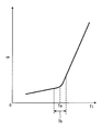
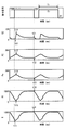
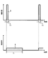
- FIG. 3 is a characteristic diagram showing a relationship between a total injection amount Q and a pulse width Ti in the first embodiment.
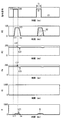
- the time chart which shows the one aspect
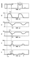
- the time chart which shows the one aspect
- the upper part is a figure by the fuel-injection system as a comparative example of 1st Embodiment, and the lower part is a figure by the fuel-injection system which concerns on 1st Embodiment.
- the schematic diagram which shows the state with which the fuel-injection system which concerns on 2nd Embodiment of this invention was mounted in the vehicle.
- the schematic diagram which shows the state by which the fuel-injection system which concerns on 3rd Embodiment of this invention was mounted in the vehicle.
- the schematic diagram which shows the state by which the fuel-injection system which concerns on 4th Embodiment of this invention was mounted in the vehicle.
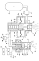
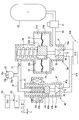
- the fuel injection system supplies fuel to an internal combustion engine 10 mounted on a vehicle.
- the internal combustion engine 10 is an ignition internal combustion engine that is ignited and combusted by an ignition device (not shown), and has a plurality of cylinders.
- the vehicle is equipped with a fuel tank 20 that stores gaseous fuel in a compressed state.
- gaseous fuel include compressed natural gas (CNG), liquefied natural gas (LNG), hydrogen, and the like.
- the gas fuel is distributed and supplied to the first injection valves 30 arranged in the respective cylinders by the distribution pipe 22. 2 is supplied to the injection valve 40.
- the first injection valve 30 and the second injection valve 40 inject the supplied gaseous fuel into the intake manifold 11.
- the intake manifold 11 corresponds to an intake pipe.
- the second injection valve 40 is disposed on the downstream side of the first injection valve 30 in the intake flow direction in the intake manifold 11. Specifically, the first injection valve 30 and the second injection valve 30 are positioned so that the second injection hole 41a of the second injection valve 40 is located downstream of the gaseous fuel injected from the first injection hole 31a of the first injection valve 30.
- the injection valve 40 is arranged.
- the intake manifold 11 is connected to an intake port 12 provided in the combustion chamber of the internal combustion engine 10, and an intake valve 14 that adjusts the intake amount of air is connected to an intake pipe 13 connected to the upstream side of the intake manifold 11. Is attached.
- the intake air adjusted by the intake valve 14 is mixed with gaseous fuel in the intake manifold 11 and flows into the combustion chamber from the intake port 12.
- An ECU (Electronic Control Unit) 50 that is an electronic control device mounted on a vehicle includes a central processing unit 51, a nonvolatile memory 52, and a volatile memory 53.
- the central processing unit 51 performs arithmetic processing according to a program stored in the nonvolatile memory 52
- the ECU 50 functions as a control unit.
- the ECU 50 controls the operation of the drive circuit 55 based on detection values of various sensors 54 mounted on the vehicle.
- the drive circuit 55 supplies drive power to the electric actuator provided in the second injection valve 40 in accordance with a command signal from the ECU 50.
- the fuel injection amount and the injection timing by the second injection valve 40 are controlled. Further, as described in detail later, the fuel injection amount and the injection timing by the first injection valve 30 are controlled by the fuel injection by the second injection valve 40. Therefore, the ECU 50 controls the fuel injection amount and the injection timing from the first injection valve 30 and the second injection valve 40 by controlling the operation of the second injection valve 40.
- the fuel injection amount by the second injection valve 40 is referred to as a second injection amount
- the fuel injection amounts from the first injection valve 30 and the second injection valve 40 are referred to as a total injection amount Q.
- the ECU 50 acquires information from the sensor 54 such as the accelerator pedal operation amount by the vehicle driver and the output shaft rotational speed (engine speed) of the internal combustion engine 10. Next, based on these pieces of information, a fuel injection amount required during one combustion cycle of the internal combustion engine 10 (hereinafter referred to as a required injection amount Qreq) is calculated. Next, the time (hereinafter referred to as pulse width Ti) for supplying drive power to the second injection valve 40 is calculated so that the total injection amount Q becomes the required injection amount Qreq. Next, a command signal is output to the drive circuit 55 so as to supply power with the calculated pulse width Ti.
- the first injection valve 30 includes a first body 31, a first valve body 32, a diaphragm 33, and a first spring 34.
- a flow path for the fuel supplied from the distribution pipe 22 is formed inside the first body 31, and a first injection hole 31 a for injecting gaseous fuel is formed at the tip of the first body 31.
- the 1st valve body 32 is accommodated in the inside of the 1st body 31, and act
- the diaphragm 33 is attached to the inside of the first body 31, and partitions the flow path into a first passage 31b and a back pressure chamber 31c. High pressure fuel regulated by the pressure regulating valve 21 is supplied to the first passage 31 b through the distribution pipe 22.
- the back surface portion 32 a of the first valve body 32 is attached to the diaphragm 33. Thereby, the diaphragm 33 and the 1st valve body 32 operate
- the back surface portion 32a faces both the first passage 31b and the back pressure chamber 31c.
- the first spring 34 is disposed in the back pressure chamber 31c, and presses the first valve body 32 toward the valve closing side by applying an elastic force to the back surface portion 32a.
- An inner communication path 32b that connects the first path 31b and the back pressure chamber 31c is formed in the back surface portion 32a.
- a first orifice 32c is provided in the internal communication path 32b. The first orifice 32c limits the flow rate so as to reduce the flow rate of the fuel flowing from the first passage 31b into the back pressure chamber 31c, and corresponds to a first flow rate limiting unit.
- the fuel pressure of the back pressure chamber 31c is applied to one surface of the diaphragm 33, and the fuel pressure of the first passage 31b is applied to the other surface. That is, the fuel pressure in the first passage 31b acts on the first valve body 32 as a valve opening force, and the fuel pressure in the back pressure chamber 31c and the elastic force of the first spring 34 act on the first valve body 32 as a valve closing force. To do. In short, when the fuel pressure in the back pressure chamber 31c decreases and the differential pressure between the first passage 31b and the back pressure chamber 31c increases, and the valve opening force due to the differential pressure becomes larger than the valve closing force by the first spring 34, The first valve body 32 is opened together with the diaphragm 33.
- the second injection valve 40 has a second body 41, a second valve body 42, an electromagnetic coil 43, a second spring 44, a fixed core 43a, and a movable core 42a.
- a second passage 41b which is a flow path of fuel supplied from the communication pipe 70, is formed inside the second body 41.
- a second injection hole 41 a for injecting gaseous fuel is formed at the tip of the second body 41.
- the second valve body 42 is accommodated in the second body 41 and operates to open and close the second injection hole 41a.
- the movable core 42 a is coupled to the second valve body 42.
- the electromagnetic coil 43, the fixed core 43a, and the movable core 42a constitute an electric actuator, and are attached to the second body 41 to constitute a magnetic circuit.
- a magnetic attractive force is generated, and the movable core 42a is attracted to the fixed core 43a.
- the magnetic attractive force acts as a valve opening force for opening the second valve body 42.
- the elastic force of the second spring 44 acts as a valve closing force for closing the second valve body 42. Accordingly, the second valve body 42 is opened by the magnetic attractive force when the electromagnetic coil 43 is turned on, and the second valve body 42 is closed by the elastic force when the electromagnetic coil 43 is turned off. .
- the communication pipe 70 is connected to the first injection valve 30 and the second injection valve 40 so as to communicate the second passage 41b and the back pressure chamber 31c. Thereby, the gaseous fuel in the fuel tank 20 flows through the distribution pipe 22, the first passage 31 b, the back pressure chamber 31 c, and the communication pipe 70 in order, and is supplied to the second passage 41 b of the second injection valve 40.
- a second orifice 71 is provided inside the communication pipe 70.
- the second orifice 71 restricts the flow rate so that the flow rate of the fuel flowing from the back pressure chamber 31c into the second passage 41b decreases, and corresponds to a communication flow rate restricting unit.
- the degree by which the flow rate is restricted by the second orifice 71 is set larger than the degree by which the flow rate is restricted by the second nozzle hole 41a. That is, the opening area of the second orifice 71 is set smaller than the opening area of the second injection hole 41a.
- the degree of restriction by restricting the flow rate by the first orifice 32c is set larger than the degree of restriction by restricting the flow rate by the second orifice 71. That is, the opening area of the first orifice 32 c is set smaller than the opening area of the second orifice 71.
- the fuel pressure in the first passage 31b (hereinafter referred to as the first fuel pressure P1)
- the fuel pressure in the back pressure chamber 31c (hereinafter referred to as the back pressure Pm)
- the fuel pressure in the second passage 41b (hereinafter referred to as the following)
- the second fuel pressure P2 is changed with a propagation delay.
- the back pressure Pm also decreases.
- the second orifice 71 functions to delay the propagation of the fuel pressure drop so that the back pressure Pm starts to fall behind the start time of the second fuel pressure P2 drop.
- the first orifice 32c functions to delay the propagation of the fuel pressure decrease so that the first fuel pressure P1 starts decreasing after the start time of the decrease in the back pressure Pm.
- An accumulator 72 is attached to the communication pipe 70.
- the accumulator 72 forms a storage chamber 72a for storing fuel therein.
- the volume of the storage chamber 72 a is set larger than the volume in the communication pipe 70.
- the fuel pressure in the storage chamber 72a matches the fuel pressure in the second passage 41b.
- the accumulator 72 includes a movable plate 72b and an elastic member 72c.
- the movable plate 72b moves according to the fuel pressure in the storage chamber 72a to change the volume of the storage chamber 72a.
- the elastic member 72c applies an elastic force to the movable plate 72b in a direction to reduce the volume of the storage chamber 72a.
- the movable plate 72b moves and the volume of the storage chamber 72a decreases, and the volume in the storage chamber 72a increases.
- the fuel is supplied to the second passage 41b. Therefore, the accumulator 72 functions so as to slow down the speed at which the second fuel pressure P2 decreases with fuel injection by the second injection valve 40. In other words, the accumulator 72 functions to delay the propagation of the fuel pressure drop in the same manner as the second orifice 71 so that the back pressure Pm starts to fall behind the start time of the drop of the second fuel pressure P2.
- the pulse width Ti is set to be less than the predetermined value Ta (see FIG. 3) and the operation of the second injection valve 40 is controlled, the second injection valve 40 does not inject but the second injection valve 40 injects (hereinafter referred to as “the second injection valve 40”) , Described as small injection).
- the operation of the second injection valve 40 is controlled by setting the pulse width Ti to be equal to or greater than the predetermined value Ta, injection is performed from both the first injection valve 30 and the second injection valve 40 (hereinafter referred to as large injection). It becomes a state. Therefore, in the characteristic diagram of FIG.
- the total injection amount Q increases as the pulse width Ti is increased, but the total injection amount Q is greater in the region where the pulse width Ti is less than the predetermined value Ta compared to the region where the pulse width Ti is greater than the predetermined value Ta.
- the rate of increase is small.
- the large injection corresponds to the first injection, and the small injection corresponds to the second injection.
- the non-volatile memory 52 stores a map (see FIG. 3) representing the value of the pulse width Ti with respect to the total injection amount Q.
- the ECU 50 calculates a pulse width Ti corresponding to the required injection amount Qreq based on the map and outputs a command signal. Therefore, it can be said that the ECU 50 controls the pulse width Ti to be switched between the predetermined value Ta and less than the predetermined value Ta according to the required injection amount Qreq.
- the injection rate is the amount injected per unit time.
- the injection rate from the first injection hole 31a is the first injection rate R1
- the injection rate from the second injection hole 41a is the first.
- the total of two injection rates R2 and both injection rates R1 and R2 is referred to as a total injection rate R.
- FIG. 4 shows one mode in which the pulse width Ti is set so that small injection is performed.
- the pulse of the command signal is switched from OFF to ON at time t10
- the second valve body 42 starts the valve opening operation at time t11 when the magnetic attractive force by the electromagnetic coil 43 is sufficiently increased, and the second injection rate R2 is Begins to rise.
- the second fuel pressure P2 starts to decrease at time t12
- the back pressure Pm also starts to decrease at time t13 along with this decrease.
- the degree of restriction by restricting the flow rate by the second orifice 71 is set larger than the degree of restriction by restricting the flow rate by the second injection hole 41a. Therefore, the decrease rate of the back pressure Pm after the time point t13 is slower than the decrease rate of the second fuel pressure P2 after the time point t12.
- the second valve body 42 starts the valve closing operation at time t21, and the second injection rate R2 starts to decrease. Then, the degree of restriction at the second nozzle hole 41a gradually increases, and at the time t22 when the degree of restriction at the second nozzle hole 41a becomes larger than the degree of restriction at the second orifice 71, the second fuel pressure P2 is reached. Begins to rise. With this increase, the back pressure Pm also starts increasing at time t23.
- the back pressure Pm at time t23 is not sufficiently reduced to open the first valve body 32. That is, the pulse width Ti from time t10 to time t20 is less than the predetermined value Ta. Therefore, the first injection rate R1 does not increase, and the second injection rate R2 becomes zero at the time te. Therefore, the total injection rate R matches the second injection rate R2.
- a hatched area in the graph representing the total injection rate R corresponds to the total injection amount Q.
- FIG. 5 shows one mode when the pulse width Ti is set so that large injection is performed.
- the pulse of the command signal is switched on at time t10
- the second valve body 42 starts the valve opening operation at time t11 when the magnetic attractive force sufficiently increases, and the second injection rate R2 starts to increase.
- the second fuel pressure P2 starts to decrease at time t12
- the back pressure Pm also starts to decrease at time t13 along with this decrease.
- the second injection rate R2 starts to decrease.
- the first valve body 32 starts the valve opening operation, and the first injection rate R1 starts to increase.
- the pulse-off is switched in a state where the second injection rate R2 is saturated to the maximum value.
- the maximum value is a value resulting from the degree of restriction of the second nozzle hole 41a.
- the pulse-off is switched while the second injection rate R2 is decreasing.
- the second fuel pressure P2 starts to increase.
- the back pressure Pm also starts increasing at time t23.
- the first valve body 32 starts the valve closing operation, and the first injection rate R1 starts to decrease.
- the pulse width Ti from time t10 to time t20 in FIG. 5 is equal to or greater than a predetermined value Ta. Accordingly, after the second injection rate R2 rises, the first injection rate R1 also rises, and after the second injection rate R2 falls, the first injection rate R1 also falls, and the second valve body 42 is closed. At the time of te, the first valve body 32 is also closed. Therefore, the start of increase of the total injection rate R coincides with the start of increase of the second injection rate R2, and the start of decrease of the total injection rate R coincides with the start of decrease of the first injection rate R1. And the total injection rate R also becomes zero at the time te when the first injection rate R1 becomes zero. A hatched area in the graph representing the total injection rate R corresponds to the total injection amount Q.
- FIG. 6 shows an example of a case where the pulse width Ti is set so that large injection is performed, and shows an example in which the pulse width Ti is made longer than in the case of FIG.
- each of the second injection rate R2, the second fuel pressure P2, the back pressure Pm, and the first injection rate R1 is saturated to a constant value.
- the command signal pulse is switched off at time t20, the second valve body 42 starts the valve closing operation, and the second injection rate R2 starts to decrease.
- the degree of restriction at the second nozzle hole 41a gradually increases, and at the time t22 when the degree of restriction at the second nozzle hole 41a becomes larger than the degree of restriction at the second orifice 71, the second fuel pressure P2 is reached. Begins to rise. With this increase, the back pressure Pm also starts increasing at time t23. Then, at time t24 when the back pressure Pm increases to the extent that the opening of the first valve body 32 cannot be maintained, the first valve body 32 starts the valve closing operation, and the first injection rate R1 starts to decrease.
- the fuel injection system of the present embodiment described above exhibits the effects described below.
- the fuel injection system includes a first injection valve 30 having a back pressure chamber 31c, a second injection valve 40 having a second passage 41b and an electric actuator, a second passage 41b, and a back pressure chamber 31c. And a communication pipe 70 for communication. Then, the ECU 50 that controls the electric actuator switches between large injection control and small injection control according to the required injection amount.
- the large injection control is control for opening the second valve body 42 for a predetermined time or more so that the back pressure Pm is reduced to a pressure for opening the first valve body 32.
- the small injection control is control for opening the second valve body 42 for a predetermined time or less so that the back pressure Pm does not decrease to a pressure for opening the first valve body 32.
- the large injection to be injected from can be realized. Therefore, by setting the area of the second injection hole 41a smaller than the area of the first injection hole 31a while increasing the dynamic range, it is possible to improve the injection amount accuracy at the time of small injection. Moreover, the control for switching between the small injection and the large injection and the control of the injection amount at the time of the small injection and the large injection can be realized only by the control of one electric actuator. Therefore, the processing load of control by the ECU 50 can be reduced as compared with the case where an electric actuator is provided in each of the injection valves 30 and 40.
- the dynamic range of the total injection rate R can be increased. That is, the minimum value can be reduced while increasing the maximum value of the total injection rate R. Therefore, even if the required injection amount Qreq is small, the pulse width Ti can be increased (see FIG. 7). Therefore, fuel pressure pulsation that occurs on the downstream side of the second injection hole 41a during small injection can be reduced.
- the fuel injection system includes an accumulator 72 that stores gaseous fuel supplied to the second injection valve 40 through the communication pipe 70.
- the fuel injection system according to the present embodiment includes a second orifice 71 that restricts the flow rate of the gaseous fuel flowing through the communication pipe 70, that is, a communication flow rate limiting unit.
- the flow restriction amount at the second orifice 71 is set to be larger than the flow restriction amount at the second injection hole 41a.
- the back pressure Pm reduction suppression can be promoted. Therefore, it is possible to ensure a sufficiently large region of the pulse width Ti to be injected in the valve opening time of the second valve body 42 (that is, the pulse width Ti). In other words, the predetermined value Ta in FIG. 3 can be sufficiently increased.
- the fuel injection system includes a first orifice 32c that restricts the flow rate of the gaseous fuel flowing from the first passage 31b into the back pressure chamber 31c, that is, a first flow rate restricting means.
- the degree of flow restriction at the first orifice 32 c is set to be greater than the degree of flow restriction at the second orifice 71.
- the flow rate of fuel flowing from the first passage 31b to the back pressure chamber 31c is smaller than the flow rate flowing from the back pressure chamber 31c to the second passage 41b.
- the reduced state of the back pressure Pm is easily maintained. Therefore, it is possible to reduce the possibility that the reduced state of the back pressure Pm cannot be maintained during the large injection and the first valve body 32 is closed.
- the maximum injection rate by the second injection valve 40 is set smaller than the maximum injection rate by the first injection valve 30. Therefore, it is possible to promote the effect of improving the injection amount accuracy and the pressure pulsation reduction by the small injection and the effect of increasing the dynamic range by the large injection.
- the fuel of the internal combustion engine 10 is a gas
- the mixing property of the intake air and the fuel is worse than that of a liquid. Therefore, in the case of gaseous fuel, it is desired to promote intake and fuel agitation.
- the second injection hole 41a is positioned downstream of the first injection hole 31a in the intake flow direction inside the intake manifold 11 (intake pipe).
- the 1 injection valve 30 and the 2nd injection valve 40 are arrange
- the first injection valve 30 is provided in each of the plurality of cylinders.
- one first injection valve 30 is provided for a plurality of cylinders. Then, the fuel injected from the first injection valve 30 is distributed and supplied to the portion corresponding to each cylinder in the intake manifold 11 through the distribution pipe 23. Further, the fuel in the back pressure chamber 31c of one first injection valve 30 is distributed and supplied to the second injection valves 40 provided in each of the plurality of cylinders through the communication pipe 70.
- the present embodiment in addition to the same effects as the first embodiment, there is an effect that the number of the first injection valves 30 can be reduced.
- the injection amount for each cylinder can be controlled with higher accuracy during large injection than in the present embodiment.
- one first injection valve 30 is provided for a plurality of cylinders.
- the number of the first injection valves 30 is two or more and less than the number of cylinders. Then, the fuel injected from the first injection valve 30 is distributed and supplied to the portion corresponding to each cylinder in the intake manifold 11 through the distribution pipe 23. Further, the fuel in the back pressure chamber 31 c of the first injection valve 30 is distributed and supplied to the plurality of second injection valves 40 through the communication pipe 70.
- the same operational effects as those of the second embodiment can be obtained.
- the fuel injection system according to each embodiment described above supplies gaseous fuel to the internal combustion engine 10.
- the fuel injection system according to the present embodiment supplies gaseous fuel (for example, hydrogen gas) to the cell stack provided in the fuel cell 10A as shown in FIG.
- gaseous fuel for example, hydrogen gas
- a supply pipe 11A is connected to the first injection hole 31a and the second injection hole 41a, and hydrogen gas injected from the first injection hole 31a and the second injection hole 41a is supplied to the fuel cell through the supply pipe 11A. 10A.
- the same operational effects as those of the first embodiment are exhibited. Further, if a large fuel pressure pulsation is generated in the gaseous fuel supplied to the fuel cell 10A, the fuel cell 10A is deteriorated. Therefore, the above-described effects such as “the fuel pressure pulsation generated on the downstream side of the second injection hole 41a during the small injection can be reduced” are effectively exhibited.
- the required injection amount Qreq in the first embodiment is the fuel injection amount required during one combustion cycle of the internal combustion engine 10, but the required injection amount Qreq in the present embodiment is a predetermined time. This is the amount of injection required.
- the second orifice 71 may be eliminated. Further, if the degree of restriction by the second orifice 71 is sufficiently large, the accumulator 72 may be eliminated.
- the pulse width Ti is set to a value in the vicinity of the predetermined value Ta in the region of the pulse width Ti shown in FIG. 3, the certainty of controlling to switch between the large injection and the small injection becomes low. That is, when the pulse width Ti is set to a value slightly smaller than the predetermined value Ta, there is a concern that the first valve body 32 opens and large injection is performed. Further, when the pulse width Ti is set to a value slightly larger than the predetermined value Ta, there is a concern that the first valve body 32 does not open and the small injection is performed.
- setting the pulse width Ti to the value in the region of the predetermined width Tb (see FIG. 3) including the predetermined value Ta may be prohibited so as not to cause an unintended injection state.
- the excess / deficiency with respect to the required injection amount Qreq may be adjusted by the injection amount at the next injection. Or what is necessary is just to implement the multistage injection which injects in multiple times in one combustion cycle.
Landscapes
- Engineering & Computer Science (AREA)
- Chemical & Material Sciences (AREA)
- Combustion & Propulsion (AREA)
- Mechanical Engineering (AREA)
- General Engineering & Computer Science (AREA)
- Chemical Kinetics & Catalysis (AREA)
- General Chemical & Material Sciences (AREA)
- Oil, Petroleum & Natural Gas (AREA)
- Analytical Chemistry (AREA)
- Electrical Control Of Air Or Fuel Supplied To Internal-Combustion Engine (AREA)
- Fuel-Injection Apparatus (AREA)
Abstract
燃料噴射システムは、第1噴射弁(30)、第2噴射弁(40)、連通配管(70)およびECU(50)を備える。連通配管(70)は、第2噴射弁(40)の第2通路(41b)と第1噴射弁(30)の背圧室(31c)とを連通させる。ECU(50)は、第1噴射制御と第2噴射制御とを要求噴射量に応じて切り替えるよう、第2噴射弁(40)の電気アクチュエータを制御する。第1噴射制御では、背圧(Pm)が第1弁体(32)を開弁させる圧力にまで低下するよう、第2弁体(42)を所定時間以上開弁させる。第2噴射制御では、背圧(Pm)が第1弁体(32)を開弁させる圧力にまで低下しないよう、第2弁体(42)を所定時間未満開弁させる。
Description
本出願は、2013年9月25日に出願された日本出願番号2013-198622号に基づくもので、ここにその記載内容を援用する。
本開示は、例えば内燃機関や燃料電池への燃料供給に用いられる、気体燃料用の燃料噴射システムに関する。
燃料が気体の場合、液体の場合に比べて要求される噴射量のダイナミックレンジが大きい。そのため、気体燃料を噴射する噴射弁として、想定される要求噴射量の最大値を所定時間内に噴射可能な大型の噴射弁を用いると、要求噴射量が小さいときには噴射量を精度良く制御できなくなる。
そこで、特許文献1記載の燃料噴射システムは、低流量タイプの小型噴射弁、および高流量タイプの大型噴射弁の2つを備えている。そして、各々の噴射弁に備えられた電気アクチュエータを次のように制御することで、大噴射量から小噴射量までの制御を可能にしている。すなわち、要求噴射量が少ない領域では、大型噴射弁を全閉にしつつ小型噴射弁による流量制御で噴射量を制御する。また、要求噴射量が多い領域では、小型噴射弁を全開にしつつ大型噴射弁による流量制御で噴射量を制御する。
しかしながら、特許文献1記載の上記システムでは、2つの噴射弁の各々について電気アクチュエータの作動を電子制御することを要する。そのため、制御が煩雑になるとともに、制御の処理負荷増大を招く。
本開示の目的は、噴射量のダイナミックレンジを大きくしつつも、制御を簡素にして制御の処理負荷を軽減できるようにした燃料噴射システムを提供することにある。
本開示の燃料噴射システムは、気体燃料を噴射する第1噴孔を開閉する第1弁体、および気体燃料の圧力を閉弁力として第1弁体に作用させる背圧室を内部に形成する第1ボデーを有する第1噴射弁と、気体燃料を噴射する第2噴孔を開閉する第2弁体、第2噴孔へ気体燃料を流通させる第2通路を内部に形成する第2ボデー、および第2弁体に開弁力を作用させる電気アクチュエータを有する第2噴射弁と、第2通路と背圧室とを連通させる連通配管と、電気アクチュエータへの通電状態を制御して第2弁体の作動を制御する制御手段と、を備える。
制御手段は、背圧室の圧力が第1弁体を開弁させる圧力にまで低下するよう、第2弁体を所定時間以上開弁させる第1噴射制御と、背圧室の圧力が第1弁体を開弁させる圧力にまで低下しないよう、第2弁体を所定時間未満開弁させる第2噴射制御と、を要求噴射量に応じて切り替える。
これによれば、第2通路と背圧室とが連通されているので、第2弁体を開弁させると、第2噴孔から燃料が噴射されて第2通路の圧力が低下することに伴い、背圧室を圧力低下させることができる。そのため、第2弁体を開弁させて、第1弁体を開弁させる圧力にまで背圧室の圧力を低下させれば、第2弁体と第1弁体の両方を開弁させることができる。また、第2弁体の開弁時間を短くすると、背圧室の圧力は十分に低下せず、第1弁体は開弁しない。つまり、第1弁体を開弁させることなく第2弁体を開弁させることができる。
これらの点を鑑み、第1弁体を開弁させるよう第2弁体を所定時間以上開弁させる第1噴射制御と、第1弁体を開弁させないよう第2弁体を所定時間未満開弁させる第2噴射制御とを、要求噴射量に応じて切り替える。そのため、第1噴射弁に電気アクチュエータを搭載させることなく、第2噴射弁の電気アクチュエータを制御するだけで、第2噴射弁だけから噴射させる第2噴射と、両方の噴射弁から噴射させる第1噴射とを実現できる。よって、両噴射弁から噴射させる第1噴射により最大可能噴射量を大きくしつつも、第2噴射時の噴射量精度を向上できる。
しかも、第2噴射および第1噴射を切り替える制御と、第2噴射時および第1噴射時における噴射量の制御とを、1つの電気アクチュエータの制御だけで実現できる。よって、両噴射弁の各々に電気アクチュエータを設けた場合に比べて、制御の処理負荷を軽減できる。
以下に、図面を参照しながら発明を実施するための複数の形態を説明する。各形態において先行する形態で説明した事項に対応する部分には同一の参照符号を付して重複する説明を省略する場合がある。各形態において構成の一部のみを説明している場合は、構成の他の部分については先行して説明した他の形態を適用することができる。各実施形態で具体的に組合せが可能であることを明示している部分同士の組合せばかりではなく、特に組合せに支障が生じなければ、明示してなくとも実施形態同士を部分的に組み合せることも可能である。
(第1実施形態)
図1に示すように、本実施形態に係る燃料噴射システムは、車両に搭載された内燃機関10へ燃料を供給するものである。内燃機関10は、図示しない点火装置により着火燃焼する点火式内燃機関であり、複数の気筒を有する。車両には、気体燃料を圧縮した状態で貯蔵する燃料タンク20が搭載されている。気体燃料の具体例としては、圧縮天然ガス(CNG)、液化天然ガス(LNG)、水素等が挙げられる。
図1に示すように、本実施形態に係る燃料噴射システムは、車両に搭載された内燃機関10へ燃料を供給するものである。内燃機関10は、図示しない点火装置により着火燃焼する点火式内燃機関であり、複数の気筒を有する。車両には、気体燃料を圧縮した状態で貯蔵する燃料タンク20が搭載されている。気体燃料の具体例としては、圧縮天然ガス(CNG)、液化天然ガス(LNG)、水素等が挙げられる。
燃料タンク20内の気体燃料は、圧力調整弁21により圧力調整された後に、分配配管22により、各気筒に配置された第1噴射弁30に分配供給され、さらに、第1噴射弁30を通じて第2噴射弁40に供給される。これらの第1噴射弁30および第2噴射弁40は、供給された気体燃料をインテークマニホールド11内へ噴射する。インテークマニホールド11は吸気配管に相当する。
インテークマニホールド11内の吸気流れ方向において、第2噴射弁40は第1噴射弁30の下流側に配置されている。詳細には、第1噴射弁30の第1噴孔31aから噴射された気体燃料の下流側に、第2噴射弁40の第2噴孔41aが位置するよう、第1噴射弁30および第2噴射弁40は配置されている。
インテークマニホールド11は、内燃機関10の燃焼室に設けられた吸気ポート12に接続されており、インテークマニホールド11の上流側に接続された吸気管13には、空気の吸入量を調節する吸気バルブ14が取り付けられている。吸気バルブ14により調節された吸入空気は、インテークマニホールド11内にて気体燃料と混合され、吸気ポート12から燃焼室へ流入する。
車両に搭載された電子制御装置であるECU(Electronic Control Unit)50は、中央処理装置51、不揮発性メモリ52および揮発性メモリ53を備える。不揮発性メモリ52に記憶されたプログラムにしたがって中央処理装置51が演算処理することで、ECU50は、制御手段として機能する。ECU50は、車両に搭載された各種センサ54の検出値に基づき、駆動回路55の作動を制御する。駆動回路55は、ECU50からの指令信号にしたがって、第2噴射弁40が備える電気アクチュエータへ駆動電力を供給する。
これにより、第2噴射弁40による燃料噴射量と噴射タイミングが制御される。また、後に詳述するように、第2噴射弁40による燃料噴射により、第1噴射弁30による燃料噴射量と噴射タイミングが制御される。したがって、ECU50は、第2噴射弁40の作動を制御することで、第1噴射弁30および第2噴射弁40からの燃料噴射量と、噴射タイミングを制御している。以下、第2噴射弁40による燃料噴射量を第2噴射量と記載し、第1噴射弁30および第2噴射弁40からの燃料噴射量をトータル噴射量Qと記載する。
ECU50は、先ず、車両運転者によるアクセルペダル操作量や内燃機関10の出力軸回転速度(エンジン回転数)等の情報をセンサ54から取得する。次に、これらの情報に基づき、内燃機関10の1燃焼サイクル中に要求される燃料の噴射量(以下、要求噴射量Qreqと記載)を算出する。次に、トータル噴射量Qが要求噴射量Qreqとなるように、第2噴射弁40へ駆動電力を供給する時間(以下、パルス幅Tiと記載)を算出する。次に、算出したパルス幅Tiで電力供給するよう、駆動回路55へ指令信号を出力する。
図2に示すように、第1噴射弁30は、第1ボデー31、第1弁体32、ダイヤフラム33および第1スプリング34を有する。第1ボデー31の内部には、分配配管22から供給される燃料の流通経路が形成され、第1ボデー31の先端には、気体燃料を噴射する第1噴孔31aが形成されている。第1弁体32は、第1ボデー31の内部に収容され、第1噴孔31aを開閉するように作動する。ダイヤフラム33は、第1ボデー31の内部に取り付けられ、上記流通経路を第1通路31bと背圧室31cに仕切る。第1通路31bには、圧力調整弁21で調圧された高圧燃料が分配配管22を通じて供給される。
第1弁体32の背面部32aは、ダイヤフラム33に取り付けられている。これにより、ダイヤフラム33と第1弁体32は一体となって作動する。背面部32aは、第1通路31bと背圧室31cの両方に面する。第1スプリング34は、背圧室31cに配置されており、背面部32aに弾性力を付与することで、第1弁体32を閉弁側へ押し付ける。
背面部32aには、第1通路31bと背圧室31cとを連通する内部連通路32bが形成されている。内部連通路32bには、第1オリフィス32cが設けられている。第1オリフィス32cは、第1通路31bから背圧室31cへ流れ込む燃料の流量を低下させるように流量制限しており、第1流量制限部に相当する。
ダイヤフラム33の一面には背圧室31cの燃料の圧力が付与され、他面には第1通路31bの燃料の圧力が付与される。つまり、第1通路31bの燃圧は、開弁力として第1弁体32に作用し、背圧室31cの燃圧および第1スプリング34の弾性力は、閉弁力として第1弁体32に作用する。要するに、背圧室31cの燃圧が低下して第1通路31bと背圧室31cとの差圧が大きくなり、その差圧による開弁力が第1スプリング34による閉弁力よりも大きくなると、ダイヤフラム33とともに第1弁体32は開弁作動する。
図2に示すように、第2噴射弁40は、第2ボデー41、第2弁体42、電磁コイル43、第2スプリング44、固定コア43aおよび可動コア42aを有する。第2ボデー41の内部には、連通配管70から供給される燃料の流通経路である第2通路41bが形成されている。第2ボデー41の先端には、気体燃料を噴射する第2噴孔41aが形成されている。
第2弁体42は、第2ボデー41の内部に収容され、第2噴孔41aを開閉するように作動する。可動コア42aは第2弁体42に結合されている。電磁コイル43、固定コア43aおよび可動コア42aは、電気アクチュエータを構成するものであり、第2ボデー41に取り付けられて磁気回路を構成する。駆動回路55から電磁コイル43へ電力供給されると磁気吸引力が生じ、可動コア42aが固定コア43aに吸引される。
つまり、磁気吸引力は、第2弁体42を開弁させる開弁力として作用する。一方、第2スプリング44の弾性力は、第2弁体42を閉弁させる閉弁力として作用する。したがって、電磁コイル43への通電オンに伴い、第2弁体42は磁気吸引力により開弁作動し、電磁コイル43への通電オフに伴い、第2弁体42は弾性力により閉弁作動する。
連通配管70は、第2通路41bと背圧室31cとを連通させるよう、第1噴射弁30および第2噴射弁40に接続されている。これにより、燃料タンク20内の気体燃料は、分配配管22、第1通路31b、背圧室31c、連通配管70を順に流通して、第2噴射弁40の第2通路41bへ供給される。
連通配管70の内部には、第2オリフィス71が設けられている。第2オリフィス71は、背圧室31cから第2通路41bへ流れ込む燃料の流量が低下するように流量制限しており、連通流量制限部に相当する。第2オリフィス71で絞られて流量制限される度合いは、第2噴孔41aで絞られて流量制限される度合いよりも大きく設定されている。つまり、第2オリフィス71の開口面積は第2噴孔41aの開口面積よりも小さく設定されている。また、第1オリフィス32cで絞られて流量制限される度合いは、第2オリフィス71で絞られて流量制限される度合いよりも大きく設定されている。つまり、第1オリフィス32cの開口面積は第2オリフィス71の開口面積よりも小さく設定されている。
これらの設定により、第1通路31b内の燃圧(以下、第1燃圧P1と記載)、背圧室31c内の燃圧(以下、背圧Pmと記載)、および第2通路41b内の燃圧(以下、第2燃圧P2と記載)は、伝播遅れを伴って変化するようになる。例えば、第2噴射弁40から燃料を噴射して第2燃圧P2が低下すると、背圧Pmも低下する。このとき、第2燃圧P2の低下開始時期よりも遅れて背圧Pmが低下開始するよう、第2オリフィス71は燃圧低下の伝播を遅延させるように機能する。同様に、背圧Pmの低下開始時期よりも遅れて第1燃圧P1が低下開始するよう、第1オリフィス32cは燃圧低下の伝播を遅延させるように機能する。
連通配管70にはアキュムレータ72が取り付けられている。アキュムレータ72は、燃料を溜める貯留室72aを内部に形成する。貯留室72aの容積は、連通配管70内の容積に比べて大きく設定されている。貯留室72a内の燃圧は第2通路41b内の燃圧と一致する。アキュムレータ72は、可動板72bおよび弾性部材72cを備える。可動板72bは、貯留室72aの燃圧に応じて移動して貯留室72aの容積を変化させる。弾性部材72cは、貯留室72aの容積を小さくする方向に弾性力を可動板72bに付与する。
したがって、第2噴射弁40から燃料を噴射して第2通路41b内の燃圧が低下していくにつれ、可動板72bが移動して貯留室72aの容積は小さくなっていき、貯留室72a内の燃料は第2通路41bへ供給されていく。そのため、アキュムレータ72は、第2噴射弁40による燃料噴射に伴い第2燃圧P2が低下する速度を遅くさせるように機能する。換言すれば、第2燃圧P2の低下開始時期よりも遅れて背圧Pmが低下開始するよう、アキュムレータ72は第2オリフィス71と同様にして燃圧低下の伝播を遅延させるように機能する。
このように、第2通路41bと背圧室31cとが連通されているので、第2弁体42を開弁させると、第2噴孔41aから燃料が噴射されて第2燃圧P2が低下することに伴い、背圧Pmを低下させることができる。そのため、第2弁体42を開弁させて、第1弁体32を開弁させる圧力にまで背圧Pmを低下させれば、第2弁体42と第1弁体32の両方を開弁させることができる。また、第2弁体42を開弁させてから短時間で閉弁させると、背圧Pmは十分に低下せず、第1弁体32は開弁しない。つまり、第1弁体32を開弁させることなく第2弁体42を開弁させることができる。
要するに、パルス幅Tiを所定値Ta(図3参照)未満に設定して第2噴射弁40の作動を制御すると、第1噴射弁30からは噴射されずに第2噴射弁40から噴射(以下、小噴射と記載)される状態になる。一方、パルス幅Tiを所定値Ta以上に設定して第2噴射弁40の作動を制御すると、第1噴射弁30および第2噴射弁40の両方から噴射(以下、大噴射と記載)される状態になる。したがって、図3の特性図において、パルス幅Tiを大きくするほどトータル噴射量Qは増大するが、パルス幅Tiが所定値Ta未満の領域では、所定値Ta以上の領域に比べてトータル噴射量Qの増加率が小さい。なお、上記大噴射は第1噴射に相当し、上記小噴射は第2噴射に相当する。
不揮発性メモリ52には、トータル噴射量Qに対するパルス幅Tiの値を表したマップ(図3参照)が記憶されている。ECU50は、要求噴射量Qreqに対応するパルス幅Tiを上記マップに基づき算出して指令信号を出力する。したがって、要求噴射量Qreqに応じて、パルス幅Tiを所定値Ta以上と所定値Ta未満に切り替えるようECU50は制御していると言える。
次に、図4~図6を用いて、各種圧力および噴射率の変化がパルス幅Tiに応じて異なってくる様子を説明する。なお、上記噴射率とは、単位時間当たりに噴射される量のことであり、以下、第1噴孔31aからの噴射率を第1噴射率R1、第2噴孔41aからの噴射率を第2噴射率R2、両噴射率R1、R2の合計をトータル噴射率Rと記載する。
図4は、小噴射するようにパルス幅Tiが設定されている場合の一態様を示す。指令信号のパルスがt10時点でオフからオンに切り替わると、電磁コイル43による磁気吸引力が十分に上昇したt11時点で、第2弁体42が開弁作動を開始し、第2噴射率R2が上昇し始める。その後、t12時点で第2燃圧P2が低下し始め、この低下に伴い背圧Pmもt13時点で低下し始める。先述したように、第2オリフィス71で絞られて流量制限される度合いは、第2噴孔41aで絞られて流量制限される度合いよりも大きく設定されている。そのため、t12時点以降の第2燃圧P2の低下速度より、t13時点以降の背圧Pmの低下速度の方が遅い。
その後、指令信号のパルスがt20時点でオンからオフに切り替わると、t21時点で、第2弁体42が閉弁作動を開始し、第2噴射率R2が低下し始める。すると、第2噴孔41aで絞られる度合いが徐々に大きくなっていき、第2噴孔41aでの絞り度合いが第2オリフィス71での絞り度合いよりも大きくなったt22時点で、第2燃圧P2が上昇し始める。そして、この上昇に伴い背圧Pmもt23時点で上昇し始める。
このt23時点での背圧Pmは、第1弁体32を開弁させるほどには十分低下していない。つまり、t10時点からt20時点までのパルス幅Tiは所定値Ta未満である。したがって、第1噴射率R1は上昇することなく、第2噴射率R2はte時点でゼロになる。よって、トータル噴射率Rは第2噴射率R2と一致する。なお、トータル噴射率R表すグラフ中の斜線を付した面積はトータル噴射量Qに相当する。
図5は、大噴射するようにパルス幅Tiが設定されている場合の一態様を示す。指令信号のパルスがt10時点でオンに切り替わると、磁気吸引力が十分に上昇したt11時点で第2弁体42が開弁作動を開始し、第2噴射率R2が上昇し始める。その後、t12時点で第2燃圧P2が低下し始め、この低下に伴い背圧Pmもt13時点で低下し始める。
その後、アキュムレータ72の可動板72bが下限位置、つまり貯留室72aの容積を最小にする位置まで移動したt14時点で、第2噴射率R2が低下し始める。そして、第1弁体32を開弁させるほどに背圧Pmが十分低下したt15時点で、第1弁体32が開弁作動を開始し、第1噴射率R1が上昇し始める。
その後、指令信号のパルスがt20時点でオフに切り替わると、第2弁体42が閉弁作動を開始する。図4の例では、第2噴射率R2が最大値に飽和した状態でパルスオフに切り替えている。上記最大値は、第2噴孔41aの絞り度合いに起因した値である。これに対し、図5の例では、第2噴射率R2が低下している最中にパルスオフに切り替えている。その後、第2噴孔41aでの絞り度合いが第2オリフィス71での絞り度合いよりも大きくなったt22時点で、第2燃圧P2が上昇し始める。そして、この上昇に伴い背圧Pmもt23時点で上昇し始める。そして、第1弁体32の開弁を維持できないほどに背圧Pmが上昇したt24時点で、第1弁体32が閉弁作動を開始し、第1噴射率R1が低下し始める。
図5におけるt10時点からt20時点までのパルス幅Tiは所定値Ta以上である。したがって、第2噴射率R2の上昇に遅れて第1噴射率R1も上昇し、第2噴射率R2の低下に遅れて第1噴射率R1も低下し、第2弁体42が閉弁した後のte時点で第1弁体32も閉弁する。よって、トータル噴射率Rの上昇開始は第2噴射率R2の上昇開始と一致し、トータル噴射率Rの低下開始は第1噴射率R1の低下開始と一致する。そして、第1噴射率R1がゼロになったte時点でトータル噴射率Rもゼロになる。なお、トータル噴射率R表すグラフ中の斜線を付した面積はトータル噴射量Qに相当する。
図6は、大噴射するようにパルス幅Tiが設定されている場合の一態様であって、図5の場合よりもパルス幅Tiを長くした場合の一例を示す。指令信号のパルスがt10時点でオンに切り替わると、磁気吸引力が十分に上昇したt11時点で第2弁体42が開弁作動を開始し、第2噴射率R2が上昇し始める。その後、t12時点で第2燃圧P2が低下し始め、この低下に伴い背圧Pmもt13時点で低下し始める。
その後、アキュムレータ72の可動板72bが下限位置まで移動したt14時点で、第2噴射率R2が低下し始める。そして、背圧Pmが十分低下したt15時点で第1弁体32が開弁作動を開始し、第1噴射率R1が上昇し始める。
その後、パルスオンの状態が継続されることにより、第2噴射率R2、第2燃圧P2、背圧Pmおよび第1噴射率R1の各々は、一定の値に飽和した状態になる。そして、このような飽和状態になっている最中に、指令信号のパルスがt20時点でオフに切り替わり、第2弁体42が閉弁作動を開始し、第2噴射率R2が低下し始める。すると、第2噴孔41aで絞られる度合いが徐々に大きくなっていき、第2噴孔41aでの絞り度合いが第2オリフィス71での絞り度合いよりも大きくなったt22時点で、第2燃圧P2が上昇し始める。そして、この上昇に伴い背圧Pmもt23時点で上昇し始める。そして、第1弁体32の開弁を維持できないほどに背圧Pmが上昇したt24時点で、第1弁体32が閉弁作動を開始し、第1噴射率R1が低下し始める。
図6の例では、第1噴射率R1が低下している最中に、次の噴射指令が為されてパルスオンに切り替わっている。そのため、パルスオンのt10時点では、第2噴射率R2はゼロになっているのに対し、第1噴射率R1はゼロになっていない。よって、第2噴射弁40からの燃料噴射はパルスオン毎に途切れるのに対し、第1噴射弁30からは途切れることなく燃料が噴射される。
以上に説明した本実施形態の燃料噴射システムは、以下に説明する作用効果が発揮される。
本実施形態に係る燃料噴射システムは、背圧室31cを有する第1噴射弁30と、第2通路41bおよび電気アクチュエータを有する第2噴射弁40と、第2通路41bと背圧室31cとを連通させる連通配管70と、を備える。そして、電気アクチュエータを制御するECU50は、大噴射制御と小噴射制御とを要求噴射量に応じて切り替える。大噴射制御とは、背圧Pmが第1弁体32を開弁させる圧力にまで低下するよう、第2弁体42を所定時間以上開弁させる制御である。小噴射制御とは、背圧Pmが第1弁体32を開弁させる圧力にまで低下しないよう、第2弁体42を所定時間未満開弁させる制御である。
そのため、第1噴射弁30に電気アクチュエータを搭載させることなく、第2噴射弁40の電気アクチュエータを制御するだけで、第2噴射弁40だけから噴射させる小噴射と、両方の噴射弁30、40から噴射させる大噴射とを実現できる。よって、ダイナミックレンジを大きくしつつも、第2噴孔41a面積を第1噴孔31a面積よりも小さく設定することで、小噴射時の噴射量精度向上を図ることができる。しかも、小噴射および大噴射を切り替える制御と、小噴射時および大噴射時における噴射量の制御とを、1つの電気アクチュエータの制御だけで実現できる。よって、両噴射弁30、40の各々に電気アクチュエータを設けた場合に比べて、ECU50による制御の処理負荷を軽減できる。
ここで、本実施形態に反して1つの噴射弁で大きなダイナミックレンジを確保しようとすると、噴孔面積を大きくせざるを得なくなるので、要求噴射量Qreqが少ない場合にはパルス幅Tiが短くなる(図7参照)。すると、噴孔の下流側にて大きな燃圧脈動が生じるようになる。
これに対し、本実施形態によれば、トータル噴射率Rのダイナミックレンジを大きくできる。つまり、トータル噴射率Rの最大値を大きくしつつも最小値を小さくできる。よって、要求噴射量Qreqが少ない場合であってもパルス幅Tiを長くできる(図7参照)。そのため、小噴射時に第2噴孔41aの下流側で生じる燃圧脈動を低減できる。
本実施形態に係る燃料噴射システムは、連通配管70を通じて第2噴射弁40へ供給される気体燃料を溜めるアキュムレータ72を備える。
これによれば、第2弁体42を開弁させると、アキュムレータ72に溜められていた燃料が第2通路41bへ供給されるので、第2燃圧P2の低下が抑制される。そのため、第2弁体42の開弁に伴い生じる背圧Pmの低下が抑制されるので、第1弁体32を開弁させずに第2弁体42を開弁させる小噴射を、確実に実現できる。
本実施形態に係る燃料噴射システムは、連通配管70を流通する気体燃料の流量を制限する第2オリフィス71、つまり連通流量制限部を、備える。
これによれば、第2弁体42の開弁に伴い第2燃圧P2が低下しても、背圧室31cから第2通路41bへの燃料流れが制限されるので、背圧Pmの低下が抑制される。よって、第1弁体32を開弁させずに第2弁体42を開弁させる小噴射を、確実に実現できる。
本実施形態に係る燃料噴射システムでは、第2オリフィス71での流量制限量が、第2噴孔41aでの流量制限量よりも大きく設定されている。
これによれば、第2弁体42の開弁状態において、背圧室31cから第2通路41bへ流れる燃料の流量が、第2噴孔41aから噴射される流量よりも少なくなるので、背圧Pmの低下抑制を促進できる。よって、第2弁体42の開弁時間(つまりパルス幅Ti)のうち、小噴射させるパルス幅Tiの領域を十分に大きく確保できる。換言すれば、図3中の所定値Taを十分に大きくできる。
本実施形態に係る燃料噴射システムは、第1通路31bから背圧室31cへ流れ込む気体燃料の流量を制限する第1オリフィス32c、つまり第1流量制限手段を、備える。そして、第1オリフィス32cで流量制限される度合いが、第2オリフィス71で流量制限される度合いよりも大きく設定されている。
これによれば、第1弁体32の開弁状態において、第1通路31bから背圧室31cへ流れる燃料の流量が、背圧室31cから第2通路41bへ流れる流量よりも少なくなるので、背圧Pmの低下状態が維持されやすくなる。よって、大噴射中に、背圧Pmの低下状態が維持できなくなって第1弁体32が閉弁してしまう虞を低減できる。
本実施形態に係る燃料噴射システムでは、第2噴射弁40による最大噴射率が、第1噴射弁30による最大噴射率よりも小さく設定されている。そのため、小噴射による噴射量精度向上および圧力脈動低減の効果と、大噴射によるダイナミックレンジ増大の効果を促進できる。
ここで、内燃機関10の燃料が気体の場合、液体の場合に比べて吸気と燃料の混合性が悪くなる。そこで、気体燃料の場合には吸気と燃料の攪拌を促進させることが望まれている。
この点を鑑み、本実施形態に係る燃料噴射システムでは、インテークマニホールド11(吸気配管)の内部の吸気流れ方向において、第1噴孔31aの下流側に第2噴孔41aが位置するよう、第1噴射弁30および第2噴射弁40は配置されている。
そのため、大噴射時において、第1噴孔31aから噴射された燃料に第2噴孔41aから噴射された燃料が衝突するので、燃料の流れが乱されるようになる。よって、吸気と燃料の攪拌を促進できる。
(第2実施形態)
図1に示す上記第1実施形態では、複数の気筒の各々に第1噴射弁30を設けている。これに対し、図8に示す本実施形態では、複数の気筒に対して第1噴射弁30を1つ設けている。そして、第1噴射弁30から噴射された燃料は、分配配管23により、インテークマニホールド11のうち各々の気筒に対応する部分へ分配して供給される。また、1つの第1噴射弁30の背圧室31cの燃料は、連通配管70により、複数気筒の各々に設けられた第2噴射弁40へ分配して供給される。
図1に示す上記第1実施形態では、複数の気筒の各々に第1噴射弁30を設けている。これに対し、図8に示す本実施形態では、複数の気筒に対して第1噴射弁30を1つ設けている。そして、第1噴射弁30から噴射された燃料は、分配配管23により、インテークマニホールド11のうち各々の気筒に対応する部分へ分配して供給される。また、1つの第1噴射弁30の背圧室31cの燃料は、連通配管70により、複数気筒の各々に設けられた第2噴射弁40へ分配して供給される。
本実施形態によれば、上記第1実施形態と同様の作用効果が奏されるのに加え、第1噴射弁30の個数を削減できるといった効果も奏される。但し、複数気筒の各々に第1噴射弁30を設ける第1実施形態によれば、大噴射時において、本実施形態に比べて各気筒に対する噴射量を高精度で制御できる。
(第3実施形態)
図8に示す上記第2実施形態では、複数の気筒に対して第1噴射弁30を1つ設けている。これに対し、図9に示す本実施形態では、第1噴射弁30を、2つ以上かつ気筒数よりも少ない数だけ設けている。そして、第1噴射弁30から噴射された燃料は、分配配管23により、インテークマニホールド11のうち各々の気筒に対応する部分へ分配して供給される。また、第1噴射弁30の背圧室31cの燃料は、連通配管70により、複数の第2噴射弁40へ分配して供給される。以上により、本実施形態によっても、上記第2実施形態と同様の作用効果が奏される。
図8に示す上記第2実施形態では、複数の気筒に対して第1噴射弁30を1つ設けている。これに対し、図9に示す本実施形態では、第1噴射弁30を、2つ以上かつ気筒数よりも少ない数だけ設けている。そして、第1噴射弁30から噴射された燃料は、分配配管23により、インテークマニホールド11のうち各々の気筒に対応する部分へ分配して供給される。また、第1噴射弁30の背圧室31cの燃料は、連通配管70により、複数の第2噴射弁40へ分配して供給される。以上により、本実施形態によっても、上記第2実施形態と同様の作用効果が奏される。
(第4実施形態)
上述した各実施形態に係る燃料噴射システムは、内燃機関10へ気体燃料を供給するものである。これに対し、本実施形態に係る燃料噴射システムは、図10に示すように、燃料電池10Aが備えるセルスタックへ気体燃料(例えば水素ガス)を供給する。具体的には、第1噴孔31aおよび第2噴孔41aには供給配管11Aが接続され、第1噴孔31aおよび第2噴孔41aから噴射された水素ガスは、供給配管11Aにより燃料電池10Aへ供給される。
上述した各実施形態に係る燃料噴射システムは、内燃機関10へ気体燃料を供給するものである。これに対し、本実施形態に係る燃料噴射システムは、図10に示すように、燃料電池10Aが備えるセルスタックへ気体燃料(例えば水素ガス)を供給する。具体的には、第1噴孔31aおよび第2噴孔41aには供給配管11Aが接続され、第1噴孔31aおよび第2噴孔41aから噴射された水素ガスは、供給配管11Aにより燃料電池10Aへ供給される。
本実施形態によれば、上記第1実施形態と同様の作用効果が奏される。また、燃料電池10Aに供給される気体燃料に大きな燃圧脈動が生じていると、燃料電池10Aの劣化を招く。そのため、「小噴射時に第2噴孔41aの下流側で生じる燃圧脈動を低減できる」といった先述の効果が、有効に発揮される。
なお、第1実施形態における要求噴射量Qreqとは、内燃機関10の1燃焼サイクル中に要求される燃料の噴射量のことであったが、本実施形態における要求噴射量Qreqとは、所定時間当たりに要求される噴射量のことである。
(他の実施形態)
本発明は上記実施形態の記載内容に限定されず、以下のように変更して実施してもよい。また、各実施形態の特徴的構成をそれぞれ任意に組み合わせるようにしてもよい。
本発明は上記実施形態の記載内容に限定されず、以下のように変更して実施してもよい。また、各実施形態の特徴的構成をそれぞれ任意に組み合わせるようにしてもよい。
図2に示すアキュムレータ72は、可動板72bおよび弾性部材72cを備えているが、可動板72bおよび弾性部材72cを備えていないアキュムレータを採用してもよい。
アキュムレータ72の容積が十分に大きければ、第2オリフィス71を廃止してもよい。また、第2オリフィス71による絞り度合いが十分に大きければ、アキュムレータ72を廃止してもよい。
ここで、図3に示すパルス幅Tiの領域のうち、所定値Ta近傍の値にパルス幅Tiを設定すると、大噴射と小噴射を切り替えるように制御することの確実性が低くなる。つまり、所定値Taより僅かに小さい値にパルス幅Tiを設定した場合には、第1弁体32が開弁して大噴射になってしまう懸念がある。また、所定値Taより僅かに大きい値にパルス幅Tiを設定した場合には、第1弁体32が開弁せずに小噴射になってしまう懸念がある。
そこで、所定値Taを含む所定幅Tb(図3参照)の領域の値には、パルス幅Tiを設定することを禁止して、意図に反した噴射状態にならないように図ってもよい。この場合、要求噴射量Qreqに対する過不足分は、次回噴射時の噴射量で調整すればよい。或いは、1燃焼サイクル中に複数回噴射する多段噴射を実施すればよい。
Claims (7)
- 気体燃料を噴射する第1噴孔(31a)を開閉する第1弁体(32)、および気体燃料の圧力を閉弁力として前記第1弁体に作用させる背圧室(31c)を内部に形成する第1ボデー(31)を有する第1噴射弁(30)と、
気体燃料を噴射する第2噴孔(41a)を開閉する第2弁体(42)、前記第2噴孔へ気体燃料を流通させる第2通路(41b)を内部に形成する第2ボデー(41)、および前記第2弁体に開弁力を作用させる電気アクチュエータ(43、43a、42a)を有する第2噴射弁(40)と、
前記第2通路と前記背圧室とを連通させる連通配管(70)と、
前記電気アクチュエータへの通電状態を制御して前記第2弁体の作動を制御する制御部(50)と、
を備え、
前記制御部は、
前記背圧室の圧力が前記第1弁体を開弁させる圧力にまで低下するよう、前記第2弁体を所定時間以上開弁させる第1噴射制御と、
前記背圧室の圧力が前記第1弁体を開弁させる圧力にまで低下しないよう、前記第2弁体を所定時間未満開弁させる第2噴射制御と、
を要求噴射量に応じて切り替えることを特徴とする燃料噴射システム。 - 前記連通配管に設けられ、前記連通配管を通じて前記第2噴射弁へ供給される気体燃料を溜めるアキュムレータ(72)を備えることを特徴とする請求項1に記載の燃料噴射システム。
- 前記連通配管を流通する気体燃料の流量を制限する連通流量制限部(71)を備えることを特徴とする請求項1または2に記載の燃料噴射システム。
- 前記連通流量制限部で流量制限される流量が、前記第2噴孔で流量制限される流量よりも大きく設定されていることを特徴とする請求項3に記載の燃料噴射システム。
- 前記第1ボデーの内部には、前記第1噴孔へ気体燃料を流通させる通路であって、前記背圧室と連通されている第1通路(31b)が形成されており、
前記第1通路から前記背圧室へ流れ込む気体燃料の流量を制限する第1流量制限手段(32c)を備え、
前記第1流量制限手段で流量制限される流量が、前記連通流量制限手段で流量制限される流量よりも大きく設定されていることを特徴とする請求項4に記載の燃料噴射システム。 - 前記第2噴射弁による最大噴射率が、前記第1噴射弁による最大噴射率よりも小さく設定されていることを特徴とする請求項1~5のいずれか1つに記載の燃料噴射システム。
- 前記第1噴射弁および前記第2噴射弁は、内燃機関(10)の燃焼室に吸気を流入させる吸気配管(11)に取り付けられており、
前記吸気配管の内部の吸気流れ方向において、前記第1噴孔の下流側に前記第2噴孔が位置するよう、前記第1噴射弁および前記第2噴射弁は配置されていることを特徴とする請求項1~6のいずれか1つに記載の燃料噴射システム。
Priority Applications (1)
| Application Number | Priority Date | Filing Date | Title |
|---|---|---|---|
| US15/022,230 US10030612B2 (en) | 2013-09-25 | 2014-09-01 | Fuel-injection system |
Applications Claiming Priority (2)
| Application Number | Priority Date | Filing Date | Title |
|---|---|---|---|
| JP2013198622A JP5949715B2 (ja) | 2013-09-25 | 2013-09-25 | 燃料噴射システム |
| JP2013-198622 | 2013-09-25 |
Publications (1)
| Publication Number | Publication Date |
|---|---|
| WO2015045277A1 true WO2015045277A1 (ja) | 2015-04-02 |
Family
ID=52742453
Family Applications (1)
| Application Number | Title | Priority Date | Filing Date |
|---|---|---|---|
| PCT/JP2014/004467 Ceased WO2015045277A1 (ja) | 2013-09-25 | 2014-09-01 | 燃料噴射システム |
Country Status (3)
| Country | Link |
|---|---|
| US (1) | US10030612B2 (ja) |
| JP (1) | JP5949715B2 (ja) |
| WO (1) | WO2015045277A1 (ja) |
Families Citing this family (1)
| Publication number | Priority date | Publication date | Assignee | Title |
|---|---|---|---|---|
| CN109386403B (zh) * | 2018-09-29 | 2021-10-26 | 哈尔滨工程大学 | 一种用于带有双进气道的气体、双燃料发动机双阀式燃气喷射装置及其控制方法 |
Citations (5)
| Publication number | Priority date | Publication date | Assignee | Title |
|---|---|---|---|---|
| JPH0424659U (ja) * | 1990-06-19 | 1992-02-27 | ||
| JPH0611342A (ja) * | 1991-03-26 | 1994-01-21 | Kadoi Wataru | 差圧高度計 |
| JPH06123263A (ja) * | 1992-10-07 | 1994-05-06 | Hino Motors Ltd | 燃料噴射装置 |
| JP2004197625A (ja) * | 2002-12-17 | 2004-07-15 | Mitsubishi Heavy Ind Ltd | パイロット着火ガスエンジン |
| JP2013533416A (ja) * | 2010-07-02 | 2013-08-22 | ヒュンダイ ヘビー インダストリーズ カンパニー リミテッド | ディーゼルエンジン及びガスエンジン用二重燃料噴射バルブ |
Family Cites Families (17)
| Publication number | Priority date | Publication date | Assignee | Title |
|---|---|---|---|---|
| JPS61229969A (ja) * | 1985-04-04 | 1986-10-14 | Mitsui Eng & Shipbuild Co Ltd | 燃料噴射弁 |
| JPS63208664A (ja) * | 1987-02-25 | 1988-08-30 | Daihatsu Diesel Kk | 2種燃料機関の燃料噴射ノズル |
| JPH0424659A (ja) | 1990-05-18 | 1992-01-28 | Mita Ind Co Ltd | 画像形成装置 |
| US5329760A (en) * | 1991-10-07 | 1994-07-19 | Fuel Systems Textron, Inc. | Self-sustaining fuel purging fuel injection system |
| JP3304421B2 (ja) | 1992-09-30 | 2002-07-22 | いすゞ自動車株式会社 | ディーゼル機関のパイロット噴射装置 |
| FI101738B (fi) * | 1996-01-30 | 1998-08-14 | Waertsilae Nsd Oy Ab | Ruiskutusventtiilijärjestely |
| US6691649B2 (en) * | 2000-07-19 | 2004-02-17 | Bombardier-Rotax Gmbh | Fuel injection system for a two-stroke engine |
| JP2002231277A (ja) | 2001-01-30 | 2002-08-16 | Nissan Motor Co Ltd | 燃料電池システム |
| JP2003278621A (ja) * | 2002-03-25 | 2003-10-02 | Denso Corp | 機械装置 |
| JP4107277B2 (ja) * | 2004-09-27 | 2008-06-25 | 株式会社デンソー | 内燃機関用燃料噴射装置 |
| JP4218630B2 (ja) * | 2004-11-22 | 2009-02-04 | 株式会社デンソー | 内燃機関用燃料噴射装置 |
| US7556017B2 (en) * | 2006-03-31 | 2009-07-07 | Caterpillar Inc. | Twin needle valve dual mode injector |
| US8245679B2 (en) | 2008-10-22 | 2012-08-21 | Denso Corporation | Variable valve timing apparatus |
| FI123513B (fi) * | 2010-12-02 | 2013-06-14 | Waertsilae Finland Oy | Polttoaineen syöttöyksikkö, menetelmä sen käyttämiseksi ja polttomoottori |
| US8944027B2 (en) * | 2011-06-21 | 2015-02-03 | Caterpillar Inc. | Dual fuel injection compression ignition engine and method of operating same |
| JP5779432B2 (ja) | 2011-07-14 | 2015-09-16 | 川崎重工業株式会社 | 燃料ガス供給システム、及びその圧力制御方法 |
| JP2013089307A (ja) | 2011-10-13 | 2013-05-13 | Honda Motor Co Ltd | インジェクタ付き減圧弁およびこれを備えた燃料電池システム |
-
2013
- 2013-09-25 JP JP2013198622A patent/JP5949715B2/ja not_active Expired - Fee Related
-
2014
- 2014-09-01 WO PCT/JP2014/004467 patent/WO2015045277A1/ja not_active Ceased
- 2014-09-01 US US15/022,230 patent/US10030612B2/en not_active Expired - Fee Related
Patent Citations (5)
| Publication number | Priority date | Publication date | Assignee | Title |
|---|---|---|---|---|
| JPH0424659U (ja) * | 1990-06-19 | 1992-02-27 | ||
| JPH0611342A (ja) * | 1991-03-26 | 1994-01-21 | Kadoi Wataru | 差圧高度計 |
| JPH06123263A (ja) * | 1992-10-07 | 1994-05-06 | Hino Motors Ltd | 燃料噴射装置 |
| JP2004197625A (ja) * | 2002-12-17 | 2004-07-15 | Mitsubishi Heavy Ind Ltd | パイロット着火ガスエンジン |
| JP2013533416A (ja) * | 2010-07-02 | 2013-08-22 | ヒュンダイ ヘビー インダストリーズ カンパニー リミテッド | ディーゼルエンジン及びガスエンジン用二重燃料噴射バルブ |
Also Published As
| Publication number | Publication date |
|---|---|
| US10030612B2 (en) | 2018-07-24 |
| JP2015063953A (ja) | 2015-04-09 |
| JP5949715B2 (ja) | 2016-07-13 |
| US20160237955A1 (en) | 2016-08-18 |
Similar Documents
| Publication | Publication Date | Title |
|---|---|---|
| US8091530B2 (en) | High pressure fuel pump control for idle tick reduction | |
| EP3899238B1 (en) | Fuel flow control apparatus | |
| US20140174405A1 (en) | Fuel injection valve | |
| CN102364080A (zh) | 多级节流稳压电控喷油器 | |
| JP3505453B2 (ja) | 燃料噴射制御装置 | |
| JP2008215130A (ja) | ガスエンジンのインジェクタ制御装置 | |
| JP2015014221A (ja) | 高圧ポンプの制御装置 | |
| WO2017049017A1 (en) | Pressure regulator for fuel supply system | |
| CN111058969B (zh) | 燃料喷射器,用于运行燃料喷射器的方法 | |
| JP5949715B2 (ja) | 燃料噴射システム | |
| WO2015036825A1 (en) | Control device of internal combustion engine | |
| WO2014091680A1 (ja) | 内燃機関の燃料噴射制御装置及び車両の燃料噴射システム | |
| WO2015151945A1 (ja) | 内燃機関の制御装置 | |
| WO2013150728A1 (ja) | 燃料噴射制御装置 | |
| JP2013160138A (ja) | 燃料供給制御装置 | |
| JP5768351B2 (ja) | Dme燃料系統 | |
| CN101641510B (zh) | 用于调节内燃机的喷射系统的方法 | |
| JP2005113744A (ja) | 燃料噴射装置 | |
| WO2025263234A1 (ja) | 燃料噴射制御装置及びプログラム | |
| US20250116240A1 (en) | Fueling system controls including adaptation to fuel characteristics | |
| EP2077381A1 (en) | A device for supplying fuel to a combustion engine, method for operating the said device and device to control the operation of a combustion engine | |
| JP2009079485A (ja) | 燃料噴射弁 | |
| JP2012219676A (ja) | 内燃機関の燃料供給システム | |
| JPH11257184A (ja) | 内燃機関の燃料噴射装置 | |
| JP6358271B2 (ja) | 内燃機関の燃料噴射装置 |
Legal Events
| Date | Code | Title | Description |
|---|---|---|---|
| 121 | Ep: the epo has been informed by wipo that ep was designated in this application |
Ref document number: 14847157 Country of ref document: EP Kind code of ref document: A1 |
|
| WWE | Wipo information: entry into national phase |
Ref document number: 15022230 Country of ref document: US |
|
| NENP | Non-entry into the national phase |
Ref country code: DE |
|
| 122 | Ep: pct application non-entry in european phase |
Ref document number: 14847157 Country of ref document: EP Kind code of ref document: A1 |