WO2015041300A1 - Device for operating working machine - Google Patents
Device for operating working machine Download PDFInfo
- Publication number
- WO2015041300A1 WO2015041300A1 PCT/JP2014/074726 JP2014074726W WO2015041300A1 WO 2015041300 A1 WO2015041300 A1 WO 2015041300A1 JP 2014074726 W JP2014074726 W JP 2014074726W WO 2015041300 A1 WO2015041300 A1 WO 2015041300A1
- Authority
- WO
- WIPO (PCT)
- Prior art keywords
- work
- operation unit
- work front
- operating
- right operation
- Prior art date
Links
Images


Classifications
-
- E—FIXED CONSTRUCTIONS
- E02—HYDRAULIC ENGINEERING; FOUNDATIONS; SOIL SHIFTING
- E02F—DREDGING; SOIL-SHIFTING
- E02F3/00—Dredgers; Soil-shifting machines
- E02F3/04—Dredgers; Soil-shifting machines mechanically-driven
- E02F3/28—Dredgers; Soil-shifting machines mechanically-driven with digging tools mounted on a dipper- or bucket-arm, i.e. there is either one arm or a pair of arms, e.g. dippers, buckets
- E02F3/30—Dredgers; Soil-shifting machines mechanically-driven with digging tools mounted on a dipper- or bucket-arm, i.e. there is either one arm or a pair of arms, e.g. dippers, buckets with a dipper-arm pivoted on a cantilever beam, i.e. boom
-
- E—FIXED CONSTRUCTIONS
- E02—HYDRAULIC ENGINEERING; FOUNDATIONS; SOIL SHIFTING
- E02F—DREDGING; SOIL-SHIFTING
- E02F3/00—Dredgers; Soil-shifting machines
- E02F3/04—Dredgers; Soil-shifting machines mechanically-driven
- E02F3/96—Dredgers; Soil-shifting machines mechanically-driven with arrangements for alternate or simultaneous use of different digging elements
- E02F3/963—Arrangements on backhoes for alternate use of different tools
- E02F3/964—Arrangements on backhoes for alternate use of different tools of several tools mounted on one machine
-
- E—FIXED CONSTRUCTIONS
- E02—HYDRAULIC ENGINEERING; FOUNDATIONS; SOIL SHIFTING
- E02F—DREDGING; SOIL-SHIFTING
- E02F9/00—Component parts of dredgers or soil-shifting machines, not restricted to one of the kinds covered by groups E02F3/00 - E02F7/00
- E02F9/16—Cabins, platforms, or the like, for drivers
-
- E—FIXED CONSTRUCTIONS
- E02—HYDRAULIC ENGINEERING; FOUNDATIONS; SOIL SHIFTING
- E02F—DREDGING; SOIL-SHIFTING
- E02F9/00—Component parts of dredgers or soil-shifting machines, not restricted to one of the kinds covered by groups E02F3/00 - E02F7/00
- E02F9/20—Drives; Control devices
- E02F9/2004—Control mechanisms, e.g. control levers
- E02F9/2012—Setting the functions of the control levers, e.g. changing assigned functions among operations levers, setting functions dependent on the operator or seat orientation
Definitions
- the present invention relates to a double-armed work machine having two articulated work fronts used for dismantling work such as structures and wastes and civil engineering work.
- an upper swinging body is pivotably attached to a lower traveling body equipped with a traveling body, and an articulated type is attached to the upper swinging body.
- a hydraulic excavator as an example of such a working machine.
- a work front composed of a boom and an arm is connected to the upper swing body so as to be able to swing up and down, and a bucket is attached to the tip of the arm so as to be able to swing up and down to perform operations such as excavation, loading and leveling .
- breakers, crushers, grapples, and the like are attached instead of buckets so that work such as structure demolition work and waste demolition work can be performed.
- Patent Document 1 There is a technique disclosed in Patent Document 1 as a technique for solving problems caused by these operations.
- the technique disclosed in Patent Document 1 is a multi-joint type first work front having a first work tool that can be turned up and down on both the left and right sides of the front part of the upper swing body, and a second work tool that can be turned up and down. And a multi-joint type second working front equipped with a double-armed working machine.
- two operation devices for operating the first work front and the second work front are provided, one on each side of the driver's seat in the cab.
- the left side of the driver's seat has an operating arm bracket attached to the left side of the driver's seat, and the operating arm bracket can swing left and right.
- An operation lever for instructing the operation of the arm tip of the first work front is provided, one on each side of the driver's seat in the cab.
- the left side of the driver's seat has an operating arm bracket attached to the left side of the driver's seat, and the operating arm bracket can swing left and right.
- the driver may feel uncomfortable when sitting on the driver's seat by contacting with the operating lever provided inward in the horizontal direction, or excessively with respect to the operating lever. There is a possibility of damage due to application of a load.
- the present invention has been made in view of the above points, and is an operation device for a work machine that can be operated in the same manner as the prior art, and that can be prevented from being damaged by contact with an operation lever, so that a driver can sit without hindrance.
- the purpose is to provide.
- the present invention is provided in a work machine main body, a cab provided in the work machine main body or provided outside the work machine main body, and a front portion of the work machine main body.
- a first work front and a second work front which are driven to swing up and down, a driver seat provided in the driver's cab, a left operating device provided on the left side of the driver seat, and the driver seat.
- the left operating device includes a first left operating unit and a second left operating unit provided in the left operating unit.
- the right operation device includes a first right operation unit and a second right operation unit provided in the first right operation unit, and the shortest distance between the first left operation unit and the first right operation unit is When operating the first work front longer than the width of the driver seat, When operating using the 1st left operation part and the 1st right operation part, and operating the 2nd work front, it operates using the 2nd left operation part and the 2nd right operation part.
- the present invention by using the left operating device and the right operating device described above, it is possible to operate in the same manner as in the prior art, and further, it is possible to avoid damage to the operating lever, which has been difficult in the past, and the driver can sit without any trouble. can do. As a result, the present invention can improve the comfort for the driver and the life of the operation lever and the like.
- FIG. 1 is a side view showing a double-armed hydraulic excavator that is an example of a construction machine including an operating device according to a first embodiment of the present invention. It is a top view of the double arm type hydraulic excavator shown in FIG. It is a side view which shows the operating device with which the double arm type hydraulic excavator shown in FIG. 1 was equipped. It is a front view which shows the operating device shown in FIG. It is a figure which shows the principal part and input-output relationship of the control apparatus of the double arm type hydraulic excavator in the 1st Embodiment of this invention.
- FIG. 1 is a side view showing a double-arm hydraulic excavator as an example of a construction machine including an operating device according to a first embodiment of the present invention
- FIG. 2 is a plan view of the double-arm hydraulic excavator shown in FIG. FIG.
- the front of the driver's seat (upper left direction in the figure) is the front of the aircraft.
- a double-armed hydraulic excavator 1 (working machine) shown in FIG. 1 has an upper swing body 3 attached to a lower traveling body 2 so that the upper swing body 3 can turn, and a cab 4 is provided in front of the upper swing body 3.
- a left work front A (second work front) and a right work front B (first work front) are respectively provided on the front right side and front left side of the cab 4, and the engine is provided on the side and rear of the cab 4.
- 40, a pump 41, and the like are provided.
- the lower traveling body 2 includes left and right traveling motors 43a and 43b (the right traveling motor 43b is not illustrated) that are rotatably provided behind the left and right track frames 5a and 5b (the right track frame 5b is not illustrated), Left and right crawler tracks 44a and 44b (the right crawler track 44b is not shown) provided on the track frames 5a and 5b and the traveling motors 43a and 43b.
- the left and right traveling motors 43a and 43b are rotationally driven by the supply of pressure oil from the pump 41, the left and right crawler tracks 44a and 44b rotate around the track frames 5a and 5b, and the double-armed hydraulic excavator 1 travels.
- the upper turning body 3 has a turning motor 48 for turning itself, and the upper turning body 3 turns with respect to the lower traveling body 2 as the turning motor 48 rotates.
- the left work front A includes a swing post 7a (member) attached to the front left side of the upper swing body 3 so as to be swingable in the left-right direction, and the swing post 7a in the vertical direction.
- a boom 10a member that is swingably attached, an arm 12a (member) that is swingably attached to the boom 10a in the up-and-down direction, and a first arm that is rotatably attached to the arm 12a in the up-and-down direction. It has a grapple 14a (member) which is one work tool.
- the left work front A is connected to the swing post 7a and the upper swing body 3, and is connected to the swing post cylinder 9a (actuator) that swings the swing post 7a left and right, and the swing post 7a and the boom 10a.
- Boom cylinder 11a (actuator) that swings 10a up and down is connected to boom 10a and arm 12a, and is connected to arm cylinder 13a (actuator) that swings arm 12a up and down, arm 12a and work tool 14a.
- a work tool cylinder 15a (actuator) for rotating the work tool 14a up and down.
- the work tool 14a can be arbitrarily replaced with any one of a cutter, a breaker, a bucket, and other work tools in accordance with the work content.
- the right work front B is provided on the right front side of the upper swing body 3.
- the configuration of the right work front B is substantially symmetrical with the left work front A, and the subscript “a” of each member corresponding to the left work front A is indicated as “b”. Is omitted.
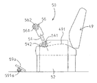
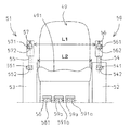
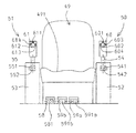
- FIG. 3 is a side view showing the operating device provided in the double-armed hydraulic excavator shown in FIG. 1, and FIG. 4 is a front view showing the operating device shown in FIG.
- a driver's seat 49 is installed in the driver's cab 4, and a left operating device 50 and a right operating device 51 are provided on the left and right sides of the driver's seat 49.
- Pedals 59a and 59b are provided.
- the left operating device 50 includes a left operating lever bracket 52 provided on the left side of the driver's seat 49, and a left operating lever 54 (first left operating portion) provided on the left operating lever bracket 52 so as to be swingable back and forth and left and right.
- a left operation switch 56 (second left operation unit) is provided at the tip of the left operation lever 54 so as to be swingable back and forth and left and right.
- the right operation device 51 includes a right operation lever bracket 53 provided on the right side of the driver's seat 49 and a right operation lever 55 (first right operation) provided on the right operation lever bracket 53 so as to be swingable back and forth and left and right. And a right operation switch 57 (second right operation unit) provided at the tip of the right operation lever 55 so as to be swingable back and forth and left and right.
- the left operation lever 54 and the right operation lever 55 are arranged in parallel with the driver seat 49, and are included in the driver seat 49, and do not overlap the seat portion 491 having the longest width, for example, the left operation lever.
- the shortest distance L1 between the lever 54 and the right operation lever 55 is longer than the width L2 of the driver seat 49.
- the left operating device 50 includes a displacement detector 541 and a displacement detector 542 that detect the amount of displacement of the left operating lever 54 that is generated by tilting in the front-rear and left-right directions.
- the displacement detector 541 detects the amount of displacement of the left operation lever 54 in the front-rear direction
- the displacement detector 542 detects the amount of displacement of the left operation lever 54 in the left-right direction.
- the tilting of the left operation lever 54 in the front-rear direction or the left-right direction indicates the driving direction of the actuator, for example, the expansion / contraction direction of the cylinder, and the amount of displacement indicates the speed with respect to the actuator.
- the right operating device 51 also includes displacement detectors 551 and 552 corresponding to the displacement detectors 541 and 542, respectively.
- the front / rear / left / right directions in which the right operation lever 55, the left operation switch 56, and the right operation switch 57 tilt are referred to as operation directions.
- the left operation device 50 includes a displacement detector 561 and a displacement detector 562 for detecting the amount of displacement of the left operation switch 56 generated by tilting in the front-rear and left-right directions.
- the displacement detector 561 detects the amount of displacement of the left operation switch 56 in the front-rear direction
- the displacement detector 562 detects the amount of displacement of the left operation switch 56 in the left-right direction.
- the left operation switch 56 tilts in the front-rear direction or in the left-right direction, that is, the operation direction described above indicates the drive direction of the actuator, for example, the expansion / contraction direction of the cylinder, and the amount of displacement indicates the speed relative to the actuator. Instruct.
- the right operating device 51 also includes displacement detectors 571 and 572 corresponding to the displacement detectors 561 and 562, respectively.
- the turning pedal 58 includes a turning pedal displacement detector 581 that detects a displacement amount of the turning pedal 58 and transmits a signal, and the left and right traveling pedals 59a and 59b detect the displacement amounts of the traveling pedals 59a and 59b. Displacement detectors 591a and 591b for traveling pedal that transmit signals are provided.
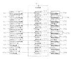
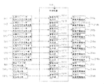
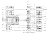
- FIG. 5 is a diagram showing the main parts and the input / output relationship of the control device for the double-armed hydraulic excavator in the first embodiment of the present invention.
- the control device 161 inputs displacement amounts from the above-described displacement detectors 541 and the like provided in the left and right operation devices 50 and 51 in the cab 4, and performs a predetermined calculation based on the displacement amounts from these input systems. Then, a drive signal is generated, and the generated drive signal is output to each solenoid valve that operates each part of the left and right work fronts A and B.
- the detector that outputs the displacement amount to the control device 161 is as described above.
- the solenoid valves output from the control device 161 are swing post drive solenoid valves 218a and 218b, boom drive solenoid valves 215a and 215b, arm drive solenoid valves 216a and 216b, work implement drive solenoid valves 217a and 217b, A turning drive solenoid valve 213 and travel drive solenoid valves 214a and 214b are provided.
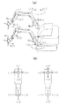
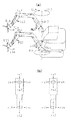
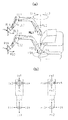
- FIG. 6 is a diagram showing the relationship between the operating direction output from the operating device according to the first embodiment of the present invention and the driving direction of the actuator of the double-armed hydraulic excavator.
- the front-rear direction displacement detector 541 of the left operation lever 54 is moved into the control device 161 as shown in FIG.
- the detection signal is output to the drive signal generator 161A.
- the drive signal generator 161A transmits the drive signal to the drive electromagnetic valve 216b of the right arm 12b.
- the right arm cylinder 13b is contracted by this drive signal, and as shown in FIG. 6A, the right arm 12b is swung forward (LL1).
- the swing speed of the right arm 12b is in a simple increase relationship, for example, a proportional relationship with the displacement amount of the longitudinal displacement detector 541, and the displacement amount detected by the longitudinal displacement detector 541 is the right arm 12b.
- the speed of the swing of the is controlled.
- the front-rear direction displacement detector 561 of the left operation switch 56 is controlled by the control device.
- a detection signal is transmitted to the drive signal generator 161E in 161.
- the drive signal generator 161E transmits a drive signal to the drive solenoid valve 216a of the left arm 12a.
- the left arm cylinder 13a is reduced by this drive signal, and the left arm 12a is swung forward as shown in FIG. 6A (LS1).
- the swing speed of the left arm 12a is simply increased, for example, proportional to the amount of displacement of the longitudinal displacement detector 561, and the displacement of the longitudinal displacement detector 561 causes the swing of the left arm 12a.
- Speed control is simply increased, for example, proportional to the amount of displacement of the longitudinal displacement detector 561, and the displacement of the longitudinal displacement detector 561 causes the swing of the left arm 12a.
- the actuators operated by the left operation lever 54, the right operation lever 55, the left operation switch 56, and the right operation switch 57 and the operation directions thereof are related to the drive generators 161A... It can be set freely by combining the valves 216a, 216b,... Therefore, it goes without saying that even in a double arm type hydraulic excavator, the actuators operated by the left operation lever 54 and the right operation lever 55 and the operation directions thereof can be made in the same manner as in the conventional hydraulic excavator.
- the left operation lever 54 and the left operation switch 56 provided on the left operation lever 54 and the left operation lever 55 and the left operation lever 55 provided on the right operation lever 55 as in the prior art.
- the left working front A and the right working front B can be operated simultaneously using the operation switch 57, and the shortest distance between the left operating lever 54 and the right operating lever 55 is included in the driver seat 49.
- the seating portion 491 having the longest width it is unlikely that the driver will come in contact with the operating means when sitting, and comfort to the driver, the left operating lever 54, or the right operating lever 55 Etc. can be improved.
- the drive direction of the actuator of the right work front B indicated by the operation direction of the right operation lever 55 and the drive direction of the actuator included in the left work front A indicated by the operation direction of the right operation switch 57 are the same. Since they are the same, the driver can operate the left and right work fronts to be operated in the same operation direction, so that the operation can be effectively learned.
- the actuator operated by the left operation lever 54 and the right operation lever 55 and the operation direction thereof can be made the same as those of the conventional hydraulic excavator, so that the conventional hydraulic excavator is operated.
- the driver does not need to learn a new operation, and can easily drive the double-arm double-arm hydraulic excavator 1.
- FIG. 7 is a diagram showing a main part of the control device for a double-armed hydraulic excavator and the input / output relationship in the second embodiment of the present invention
- FIG. 8 is an operating device in the second embodiment of the present invention. It is a figure which shows the relationship with the drive direction of the actuator which the double arm type hydraulic shovel has with respect to the operation instruction
- the only difference from the first embodiment is that the operation directions of the left operation switch 56 and the right operation switch 57 are changed, and the other configuration is the same.
- the operating directions of the left operating lever 54 and the right operating lever 55 are the same as those in the first embodiment, whereas the left operating switch 56 is moved forward as shown in FIG. 8B.
- the front-rear direction displacement detector 561 of the left operation switch 56 When displaced in the direction (ls1), the front-rear direction displacement detector 561 of the left operation switch 56 outputs a detection signal to the drive signal generation unit 161G in the control device 161 as shown in FIG. Receiving this detection signal, the drive signal generator 161G transmits a drive signal to the drive solenoid valve 215a of the left boom 11a.
- the left boom cylinder 11a is reduced by this drive signal, and as shown in FIG.
- the left boom 10a is swung downward (LS1), and the left operation switch 56 is displaced backward (ls2) to the left.
- LS1 When the boom 10a is swung upward (LS2), and the left operation switch 56 is displaced in the left direction (ls3), the left work tool 14a is swung forward (LS3), and the left operation switch 56 is moved rightward ( When displaced to ls4), the left work tool 14a is swung back (LS4).
- the drive direction of the actuator of the right work front B indicated by the operation direction of the left operation lever 54 is the same as the drive direction of the actuator included in the left work front A indicated by the operation direction of the right operation switch 57
- the drive direction of the actuator of the right work front B indicated by the operation direction of the right operation lever 55 and the drive direction of the actuator included in the left work front A indicated by the operation direction of the left operation switch 56 are the same.
- the driver can easily move the left work front A and the right work front B simultaneously with respect to the left and right work fronts to be operated. Since the swing post, the arm, and the work tool have the same configuration, the work becomes easier when the left and right actuators are simultaneously operated.
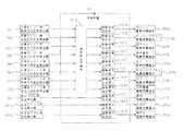
- FIG. 9 is a diagram showing the main parts and input / output relationships of the control device for a double-armed hydraulic excavator in the third embodiment of the present invention.
- a work front switching unit or an operation allocation switching unit 161Z that is an operation actuator switching unit is provided in the control device 161.
- a work front switching unit or an operation allocation switching unit 161Z that is an operation actuator switching unit is provided in the control device 161.
- the operation allocation switching unit 161Z includes displacement detectors for the left operation lever 54, the right operation lever 55, the left operation switch 56, and the right operation switch 57, and the drive signal generation units. It is provided in between.
- the operation allocation switching unit 161Z has a function of switching to which of the drive signal generation units the detection signal obtained from each displacement detector is output.
- a switch for switching three positions R, N, and C (not shown) in the cab 4 is provided, and is electrically connected to the operation assignment switching unit 161Z in the control device 161.
- the left operation switch 56 and the right operation switch 57 operate the right work front B operated by the left operation lever 54 and the right operation lever 55 with respect to the operation assignment switching unit 161Z. It has a switching instruction meaning that the left operation lever 54 and the right operation lever 55 operate the left work front A operated by the left operation switch 56 and the right operation switch 57.
- the left operation switch 56 and the right operation switch 57 operate the operation assignment switching unit 161Z on the left work front A operated by the left operation lever 54 and the right operation lever 55.
- the operation allocation switching unit 161Z changes the allocation to the electromagnetic valves 216a and 216b according to the instruction signal.
- switching between the left work front A and the right work front B is illustrated, but the present invention is not limited to this, and switching between the actuators may be performed.
- an effect equivalent to that of the first embodiment can be obtained, and the driver can select an actuator driven by each detection signal of the operation device.
- the user can select an operation assignment that is easier to operate, thereby improving workability.
- FIG. 10 is a front view showing an operating device provided in a double-armed hydraulic excavator according to the fourth embodiment of the present invention
- FIG. 11 shows a double-armed hydraulic excavator according to the fourth embodiment of the present invention. It is a figure which shows the principal part and input / output relationship of a control apparatus.
- the difference from the first embodiment is that the left operation switch 60, the right operation switch 61, and the output signals from the left operation switch 60 and the right operation switch 61 have relatively inexpensive shapes. Processing is performed in the control device 161, and the rest of the configuration is the same.
- the left operation switch 60 and the right operation switch 61 have four cross-shaped switches that can be displaced by pressing the switches, and each switch has a left operation switch 60.
- the right operation switch 61 is provided with front / rear / left / right displacement detectors 611 to 614.
- the front-rear direction or the left-right direction in which the left operation switch 60 and the right operation switch 61 are pressed indicates the driving direction of the actuator, for example, the expansion / contraction direction of the cylinder, and the amount of displacement indicates the speed with respect to the actuator.
- the front / rear and left / right directions of the operation switch 60 and the right operation switch 61 are referred to as operation directions.
- the drive signal of the control device 161 is calculated from the displacement amount output from either the front displacement detector 601 of the left operation switch 60 or the rear displacement detector 602 of the left operation switch 60.
- the driving signal generating unit 161E calculates the driving direction and speed of the left arm cylinder 13a, and outputs the driving direction to one of the solenoid valves.
- the same processing is also performed using the displacement amounts of the left operation switch 60 and the right operation switch 61 from the other displacement detectors 603, 604, 611 to 614.
- FIG. 12 is a diagram showing the relationship between the driving direction of the actuator of the double-armed hydraulic excavator and the operation direction of the operating device according to the operating instruction of the operating device in the fourth embodiment of the present invention.
- the driving direction of the double-armed hydraulic excavator, (b) shows the operating direction of the operating device.
- the operation directions of the left operation lever 54 and the right operation lever 55 are the same as those in the first embodiment, and thus description thereof is omitted.
- the left operation switch front displacement detector 601 is driven in the control device 161 as shown in FIG. A detection signal is transmitted to the signal generator 161E.
- the drive signal generator 161E transmits a drive signal to the left arm drive solenoid valve 216a.
- the left arm cylinder 13a is reduced by this drive signal, and the left arm 12a is swung forward (LS1).
- the swinging speed of the left arm 12a is in a proportional increase relationship with the displacement amount of the left operation switch front displacement detector 601, for example, the displacement of the left operation switch front displacement detector 601 is The speed of the swinging of the left arm 12a is controlled.
- the rear displacement detector 601 for the left operation switch transmits a detection signal to the drive signal generation unit 161E in the control device 161, and the left arm cylinder extends. Then, the left arm is swung back (LS2).
- the left swing post 7a is swung leftward (LS3)
- the right portion of the left operation switch 60 is pressed (ls4)
- the left swing post 7a Is swung rightward (LS4).
- the left boom 10a is swung forward (RS1), and when the rear portion of the right operation switch 61 is pressed (rs2), the left boom 10a is moved upward.
- the left operation tool 57 is swung (RS2) and the left portion of the right operation switch 57 is pressed (rs3), the left work tool 14a is swung downward (RS3), and further, the right portion of the right operation switch 57 is pressed (rs4).
- the left work tool 14a is swung upward (RS4).
- the left operation switch 60 and the right operation switch 61 have a simple structure and are inexpensive. It is effective in terms.
- the right working front B is described as having a swing post 7b, but the swing post 7b may be omitted.
- the value of the operation signal can be continuously changed. It is good also as a structure which acquires the value of an operation signal by ON / OFF by changing to a contact detector.
- the driver's seat 4 is arranged on the double-armed hydraulic excavator 1.
- the driver's seat 4 has a dual-armed hydraulic system that can be remotely operated. It is good also as a structure which exists in the position which wants to leave
- a Left working front B Right working front 1 Double-arm hydraulic excavator 2 Lower traveling body 3 Upper turning body 3a Turning center line 3c Front-rear direction center line 4
- Driver's cab 5a, 5b Track frames 7a, 7b Swing posts 9a, 9b Swing post cylinders 10a, 10b Boom 11a, 11b Boom cylinder 12a, 12b Arm 13a, 13b Arm cylinder 14a, 14b Work tool 15a, 15b Work tool cylinder 20a, 20b Grapple 21a, 21b Cutter 22a, 22b Breaker 23a, 23b Bucket 30a, 30b Swing Shaft center 31a, 31b Bottom side pin (swing cylinder) 32a, 32b Rod side pin (oscillation cylinder) 33a, 33b Bracket (Upper revolving body outside) 34a, 34b Bracket (swing post) 40 Engine 41 Pumps 42a, 42b Traveling devices 43a, 43b Traveling motors 44a, 44b Crawler belt 48 Turning
Landscapes
- Engineering & Computer Science (AREA)
- Mining & Mineral Resources (AREA)
- Civil Engineering (AREA)
- General Engineering & Computer Science (AREA)
- Structural Engineering (AREA)
- Mechanical Engineering (AREA)
- Operation Control Of Excavators (AREA)
- Mechanical Control Devices (AREA)
Abstract
A device for operating a double-arm-type hydraulic shovel (1) provided with a left operation device (50) provided on the left side of a driver seat (4) and a right operation device (51) provided on the right side of the driver seat (4), wherein the left operation device (50) includes a left operation lever (54) and a left operation switch (56) provided to the left operation lever (54), the right operation device (51) includes a right operation lever (55) and a right operation switch (57) provided to the right operation lever (55), and the shortest distance between the left operation lever (54) and the right operation lever (55) is greater than the width of the driver seat (4). When operating a right work front (B), the operation is performed using the left operation lever (54) and the right operation lever (55); when operating a left work front (A), the operation is performed using the left operation switch (56) and the right operation switch (57). It is thereby possible to perform an operation in an equivalent manner to that according to prior art, prevent damage caused by contact with an operation lever, and enable the driver to sit unhindered.
Description
本発明は、構造物や廃棄物などの解体工事や土木工事等に使用される2つの多関節型の作業フロントを備えた双腕型作業機械に関する。
The present invention relates to a double-armed work machine having two articulated work fronts used for dismantling work such as structures and wastes and civil engineering work.
構造物解体工事、廃棄物解体工事、土木建設工事等に使用される作業機械としては、走行体を備えた下部走行体に上部旋回体を旋回自在に取付け、この上部旋回体に多関節型の作業フロントを上下揺動自在に取付けたものが知られている。このような作業機械の一例として油圧ショベルがある。この油圧ショベルでは、上部旋回体にブーム・アームからなる作業フロントを上下揺動自在に連結し、アームの先端にバケットを上下揺動自在に取付け、掘削、積込み、地均し等の作業を行う。また、バケットの代わりにブレーカ、クラッシャ、グラップル等を装着して、構造物解体工事、廃棄物解体工事等の作業を行えるようにしている。
As a work machine used for structure demolition work, waste demolition work, civil engineering construction work, etc., an upper swinging body is pivotably attached to a lower traveling body equipped with a traveling body, and an articulated type is attached to the upper swinging body. There is known a work front mounted so that it can swing up and down. There is a hydraulic excavator as an example of such a working machine. In this hydraulic excavator, a work front composed of a boom and an arm is connected to the upper swing body so as to be able to swing up and down, and a bucket is attached to the tip of the arm so as to be able to swing up and down to perform operations such as excavation, loading and leveling . In addition, breakers, crushers, grapples, and the like are attached instead of buckets so that work such as structure demolition work and waste demolition work can be performed.
しかし、これら一般的な油圧ショベルでは、1台の作業機械に1台の作業フロントしか取付けられていないことにより、例えば以下のような不具合が生じる。自動車解体作業において解体用アタッチメントを用いて部品を取り外す際に、フロント作業機が1台しか取付けられていないと、当然フロント作業機は自動車の部品を取り外すものとして使用されるため、自動車本体を固定することができず、このため解体用アタッチメントで部品を取り外すときに自動車本体が不安定な挙動を示し、作業性が悪化する。
However, in these general excavators, since only one work front is attached to one work machine, for example, the following problems occur. When removing a part using the attachment for dismantling in car dismantling work, if only one front work machine is attached, naturally the front work machine is used to remove car parts, so the car body is fixed. For this reason, when the parts are removed with the disassembly attachment, the automobile body exhibits an unstable behavior and the workability is deteriorated.
また、構造物解体作業においてブレーカやクラッシャ、鉄筋カッタ等を用いて構造物を破壊する際、フロント作業機が1台しか取付けられていないと、当然フロント作業機は構造物を破壊するものとして使用されるため、構造物を把持することができない。このため、ブレーカ等で構造物を破砕するたびに、破片が落下し、さらに落下したはずみで破片が周囲に飛散するため、破片を回収して破棄する必要があり、効率が悪い。また、解体対象に保存すべき部分がある場合には、それが落下しないようにあらかじめクレーン等で吊っておく必要があり、そのための操作、作業人員も必要となる。
Also, when destroying a structure using a breaker, crusher, rebar cutter, etc. in the structure demolition work, if only one front work machine is installed, the front work machine will naturally be used to destroy the structure. Therefore, the structure cannot be gripped. For this reason, every time the structure is crushed with a breaker or the like, the debris falls, and the debris scatters to the surroundings due to the fallen pieces. Therefore, it is necessary to collect and discard the debris, which is inefficient. Further, when there is a part to be stored in the object to be dismantled, it is necessary to hang it with a crane or the like in advance so that it does not fall, and an operation and worker for that purpose are also required.
これら作業により生じる不具合を解消するための技術として、特許文献1に開示された技術がある。この特許文献1で開示された技術は、上部旋回体前部の左右両側に上下回動自在な第1作業具を備えた多関節型の第1作業フロントと上下回動自在な第2作業具を備えた多関節型の第2作業フロントとを上下揺動自在に取付けた双腕型作業機械である。
There is a technique disclosed in Patent Document 1 as a technique for solving problems caused by these operations. The technique disclosed in Patent Document 1 is a multi-joint type first work front having a first work tool that can be turned up and down on both the left and right sides of the front part of the upper swing body, and a second work tool that can be turned up and down. And a multi-joint type second working front equipped with a double-armed working machine.
特許文献1に開示された双腕型作業機械では、第1作業フロント、および第2作業フロントを操作するための操作装置が、運転室の運転席左右に1台ずつ、計2台設けている。これら操作装置の構成は、左側の操作装置を例にとると、運転席の左側には操作アームブラケット、この操作アームブラケットに左右揺動自在に取り付けられ、第1作業フロントの左右の揺動を指示する操作アーム、この操作アームに一体に揺動するように取り付けられたアームレスト、さらに操作アームの先端部分に水平方向内側(運転席側)に向けて、上下前後に回動自在に取り付けられ、第1作業フロントのアーム先端の動作を指示する操作レバー、からなる。
In the double-arm work machine disclosed in Patent Document 1, two operation devices for operating the first work front and the second work front are provided, one on each side of the driver's seat in the cab. . For example, the left side of the driver's seat has an operating arm bracket attached to the left side of the driver's seat, and the operating arm bracket can swing left and right. An operating arm for instructing, an armrest attached so as to swing integrally with this operating arm, and further attached to the tip of the operating arm so as to be able to rotate up and down and back and forth toward the inner side in the horizontal direction (driver's side) An operation lever for instructing the operation of the arm tip of the first work front.
しかし、このような構成によれば、水平方向内側に向けて備わっている操作レバーと接触することにより、運転者が運転席に着座する際に不快感を与えたり、あるいは操作レバーに対し過度の負荷を与えてしまうことで破損させたりする可能性が生ずる。
However, according to such a configuration, the driver may feel uncomfortable when sitting on the driver's seat by contacting with the operating lever provided inward in the horizontal direction, or excessively with respect to the operating lever. There is a possibility of damage due to application of a load.
本発明は上記の点に鑑みなされたもので、従来技術と同等に操作ができ、さらに操作レバーとの接触による破損を回避し、運転者が支障なく着座することができる作業機械の操作装置の提供が目的である。
The present invention has been made in view of the above points, and is an operation device for a work machine that can be operated in the same manner as the prior art, and that can be prevented from being damaged by contact with an operation lever, so that a driver can sit without hindrance. The purpose is to provide.
上記目的を達成するために、本発明は、作業機械本体と、前記作業機械本体に備えられた、もしくは作業機械本体の外に設けられた運転室と、前記作業機械本体の前部に備えられた上下揺動自在に駆動する第1の作業フロント、および第2の作業フロントと、前記運転室に備えられた運転席と、前記運転席の左側に備えられた左操作装置と、前記運転席の右側に備えられた右操作装置とを備えた作業機械の操作装置において、前記左操作装置は、第1左操作部と、前記1左操作部に備えられた第2左操作部とを含み、前記右操作装置は、第1右操作部と、前記1右操作部に備えられた第2右操作部とを含み、前記第1左操作部と前記第1右操作部との最短距離が、前記運転席の幅より長く、前記第1の作業フロントを操作する場合は、前記第1左操作部と前記第1右操作部とを用いて操作し、第2作業フロントを操作する場合は、前記第2左操作部と前記第2右操作部とを用いて操作することを特徴とする。
In order to achieve the above object, the present invention is provided in a work machine main body, a cab provided in the work machine main body or provided outside the work machine main body, and a front portion of the work machine main body. A first work front and a second work front which are driven to swing up and down, a driver seat provided in the driver's cab, a left operating device provided on the left side of the driver seat, and the driver seat. The left operating device includes a first left operating unit and a second left operating unit provided in the left operating unit. The right operation device includes a first right operation unit and a second right operation unit provided in the first right operation unit, and the shortest distance between the first left operation unit and the first right operation unit is When operating the first work front longer than the width of the driver seat, When operating using the 1st left operation part and the 1st right operation part, and operating the 2nd work front, it operates using the 2nd left operation part and the 2nd right operation part. And
本発明によれば、上述した左操作装置、および右操作装置を用いることで、従来技術と同等に操作ができ、さらに従来困難であった操作レバーの破損を回避でき、運転者が支障なく着座することができる。この結果は、本発明は運転手に対する快適性や、操作レバー等の寿命を向上することができる。
According to the present invention, by using the left operating device and the right operating device described above, it is possible to operate in the same manner as in the prior art, and further, it is possible to avoid damage to the operating lever, which has been difficult in the past, and the driver can sit without any trouble. can do. As a result, the present invention can improve the comfort for the driver and the life of the operation lever and the like.
以下に図面を用いて本発明の実施の形態を説明する。
Embodiments of the present invention will be described below with reference to the drawings.
(第1の実施の形態)
図1は、本発明の第1の実施の形態に係る操作装置を含む建設機械の一例である双腕型油圧ショベルを示す側面図、図2は図1に示した双腕型油圧ショベルの平面図である。以下の説明において断り書きのない場合は運転席の前方(同図中では左上方向)を機体の前方とする。 (First embodiment)
FIG. 1 is a side view showing a double-arm hydraulic excavator as an example of a construction machine including an operating device according to a first embodiment of the present invention, and FIG. 2 is a plan view of the double-arm hydraulic excavator shown in FIG. FIG. When there is no notice in the following description, the front of the driver's seat (upper left direction in the figure) is the front of the aircraft.
図1に示す双腕型油圧ショベル1(作業機械)は、下部走行体2に上部旋回体3が旋回可能に取付けられ、その上部旋回体3の前方に運転室4が備えられている。運転室4の前方右側及び前方左側には左作業フロントA(第2の作業フロント)および右作業フロントB(第1の作業フロント)がそれぞれ設けられ、運転室4の側方および後部にはエンジン40やポンプ41等が設けられている。
1, a double-armed hydraulic excavator 1 (working machine) shown in FIG. 1 has an upper swing body 3 attached to a lower traveling body 2 so that the upper swing body 3 can turn, and a cab 4 is provided in front of the upper swing body 3. A left work front A (second work front) and a right work front B (first work front) are respectively provided on the front right side and front left side of the cab 4, and the engine is provided on the side and rear of the cab 4. 40, a pump 41, and the like are provided.
下部走行体2は、左右トラックフレーム5a、5b(右トラックフレーム5bは図示せず)の後方に回転自在に設けられた左右走行モータ43a、43b(右走行モータ43bは図示せず)と、このトラックフレーム5a、5bと走行モータ43a、43bとに設けられた左右履帯44a、44b(右履帯44bは図示せず)とを有している。左右走行モータ43a、43bがポンプ41からの圧油の供給により、回転駆動することにより、左右履帯44a、44bがトラックフレーム5a、5bに対し周回動作し、双腕型油圧ショベル1が走行する。
The lower traveling body 2 includes left and right traveling motors 43a and 43b (the right traveling motor 43b is not illustrated) that are rotatably provided behind the left and right track frames 5a and 5b (the right track frame 5b is not illustrated), Left and right crawler tracks 44a and 44b (the right crawler track 44b is not shown) provided on the track frames 5a and 5b and the traveling motors 43a and 43b. When the left and right traveling motors 43a and 43b are rotationally driven by the supply of pressure oil from the pump 41, the left and right crawler tracks 44a and 44b rotate around the track frames 5a and 5b, and the double-armed hydraulic excavator 1 travels.
上部旋回体3はそれ自身を旋回動作させるために、旋回モータ48を有しており、この旋回モータ48が回転することにより、上部旋回体3が下部走行体2に対して旋回する。
The upper turning body 3 has a turning motor 48 for turning itself, and the upper turning body 3 turns with respect to the lower traveling body 2 as the turning motor 48 rotates.
図1および図2に示すように、左作業フロントAは、上部旋回体3の前方左側に左右方向に揺動自在に取付けられたスイングポスト7a(部材)と、このスイングポスト7aに上下方向に揺動自在に取付けられたブーム10a(部材)と、このブーム10aに上下方向に揺動自在に取付けられたアーム12a(部材)と、このアーム12aに上下方向に回動自在に取付けられた第1作業具であるグラップル14a(部材)を有する。
As shown in FIGS. 1 and 2, the left work front A includes a swing post 7a (member) attached to the front left side of the upper swing body 3 so as to be swingable in the left-right direction, and the swing post 7a in the vertical direction. A boom 10a (member) that is swingably attached, an arm 12a (member) that is swingably attached to the boom 10a in the up-and-down direction, and a first arm that is rotatably attached to the arm 12a in the up-and-down direction. It has a grapple 14a (member) which is one work tool.
また、左作業フロントAは、スイングポスト7aと上部旋回体3とに連結され、スイングポスト7aを左右揺動させるスイングポストシリンダ9a(アクチュエータ)と、スイングポスト7aとブーム10aとに連結され、ブーム10aを上下揺動させるブームシリンダ11a(アクチュエータ)と、ブーム10aとアーム12aとに連結され、アーム12aを上下揺動させるアームシリンダ13a(アクチュエータ)と、そのアーム12aと作業具14aとに連結され、作業具14aを上下回動させる作業具シリンダ15a(アクチュエータ)とを有している。なお、作業具14aは、作業内容に応じて、図中で示したグラップルの他に、カッタ、ブレーカ、バケット、その他の作業具のいずれか1つに任意に交換可能である。
The left work front A is connected to the swing post 7a and the upper swing body 3, and is connected to the swing post cylinder 9a (actuator) that swings the swing post 7a left and right, and the swing post 7a and the boom 10a. Boom cylinder 11a (actuator) that swings 10a up and down, is connected to boom 10a and arm 12a, and is connected to arm cylinder 13a (actuator) that swings arm 12a up and down, arm 12a and work tool 14a. And a work tool cylinder 15a (actuator) for rotating the work tool 14a up and down. In addition to the grapple shown in the drawing, the work tool 14a can be arbitrarily replaced with any one of a cutter, a breaker, a bucket, and other work tools in accordance with the work content.
右作業フロントBは、上部旋回体3の前方右側に設けられている。この右作業フロントBの構成は、左作業フロントAとほぼ左右対称の関係にあり、左作業フロントAの対応の各部材の符号の添字「a」を「b」として示すこととし、ここでは説明を省略する。
The right work front B is provided on the right front side of the upper swing body 3. The configuration of the right work front B is substantially symmetrical with the left work front A, and the subscript “a” of each member corresponding to the left work front A is indicated as “b”. Is omitted.
図3は、図1に示した双腕型油圧ショベルに備えられた操作装置を示す側面図、図4は、図3に示した操作装置を示す正面図を示す。
FIG. 3 is a side view showing the operating device provided in the double-armed hydraulic excavator shown in FIG. 1, and FIG. 4 is a front view showing the operating device shown in FIG.
運転室4内には運転席49が設置され、運転席49の左右両側には左操作装置50、右操作装置51が設けられており、運転席の前方下部には、旋回ペダル58、左右走行ペダル59a、59bが設けられている。
A driver's seat 49 is installed in the driver's cab 4, and a left operating device 50 and a right operating device 51 are provided on the left and right sides of the driver's seat 49. Pedals 59a and 59b are provided.
左操作装置50は、運転席49の左側に設けられた左操作レバーブラケット52と、この左操作レバーブラケット52に前後左右揺動自在に設けられた左操作レバー54(第1左操作部)、この左操作レバー54の先端部分に前後左右揺動自在に設けられた左操作スイッチ56(第2左操作部)とを備えている。
The left operating device 50 includes a left operating lever bracket 52 provided on the left side of the driver's seat 49, and a left operating lever 54 (first left operating portion) provided on the left operating lever bracket 52 so as to be swingable back and forth and left and right. A left operation switch 56 (second left operation unit) is provided at the tip of the left operation lever 54 so as to be swingable back and forth and left and right.
同様に、右操作装置51は、運転席49の右側に設けられた右操作レバーブラケット53と、この右操作レバーブラケット53に前後左右揺動自在に設けられた右操作レバー55(第1右操作部)と、この右操作レバー55の先端部分に前後左右揺動自在に設けられた右操作スイッチ57(第2右操作部)とを備えている。
Similarly, the right operation device 51 includes a right operation lever bracket 53 provided on the right side of the driver's seat 49 and a right operation lever 55 (first right operation) provided on the right operation lever bracket 53 so as to be swingable back and forth and left and right. And a right operation switch 57 (second right operation unit) provided at the tip of the right operation lever 55 so as to be swingable back and forth and left and right.
ここで、左操作レバー54、および右操作レバー55は運転席49と平行に配置されており、運転席49に含まれ、例えば最も長い幅を有す着座部491と重なりが無い、すなわち左操作レバー54、および右操作レバー55との最短距離L1が運転席49の幅L2より長い構造となっている。
Here, the left operation lever 54 and the right operation lever 55 are arranged in parallel with the driver seat 49, and are included in the driver seat 49, and do not overlap the seat portion 491 having the longest width, for example, the left operation lever. The shortest distance L1 between the lever 54 and the right operation lever 55 is longer than the width L2 of the driver seat 49.
左操作装置50は、前後左右方向に傾倒することで生ずる左操作レバー54の変位量を検出する変位検出器541と変位検出器542とを有している。変位検出器541は、左操作レバー54の前後方向の変位量を検出し、変位検出器542は、左操作レバー54の左右方向の変位量を検出する。左操作レバー54の前後方向への傾倒、もしくは左右方向への傾倒は、アクチュエータの駆動方向、例えば、シリンダの伸縮方向を指示し、また、その変位量はアクチュエータに対する速度を指示する。右操作装置51にも、変位検出器541、542にそれぞれ相当する変位検出器551、552が備わっている。なお、左操作レバー54の他、右操作レバー55、左操作スイッチ56、および右操作スイッチ57が傾倒する前後左右方向を操作方向と呼ぶ。
The left operating device 50 includes a displacement detector 541 and a displacement detector 542 that detect the amount of displacement of the left operating lever 54 that is generated by tilting in the front-rear and left-right directions. The displacement detector 541 detects the amount of displacement of the left operation lever 54 in the front-rear direction, and the displacement detector 542 detects the amount of displacement of the left operation lever 54 in the left-right direction. The tilting of the left operation lever 54 in the front-rear direction or the left-right direction indicates the driving direction of the actuator, for example, the expansion / contraction direction of the cylinder, and the amount of displacement indicates the speed with respect to the actuator. The right operating device 51 also includes displacement detectors 551 and 552 corresponding to the displacement detectors 541 and 542, respectively. In addition to the left operation lever 54, the front / rear / left / right directions in which the right operation lever 55, the left operation switch 56, and the right operation switch 57 tilt are referred to as operation directions.
また、左操作装置50は、前後左右方向に傾倒することで生ずる左操作スイッチ56の変位量を検出する変位検出器561と変位検出器562とを有している。変位検出器561は、左操作スイッチ56の前後方向の変位量を検出し、変位検出器562は、左操作スイッチ56の左右方向の変位量を検出する。左操作スイッチ56の前後方向への傾倒、もしくは左右方向への傾倒、すなわち上述した操作方向は、アクチュエータの駆動方向、例えば、シリンダの伸縮方向を指示し、また、その変位量はアクチュエータに対する速度を指示する。右操作装置51にも、変位検出器561、562にそれぞれ相当する変位検出器571、572が備わっている。
Further, the left operation device 50 includes a displacement detector 561 and a displacement detector 562 for detecting the amount of displacement of the left operation switch 56 generated by tilting in the front-rear and left-right directions. The displacement detector 561 detects the amount of displacement of the left operation switch 56 in the front-rear direction, and the displacement detector 562 detects the amount of displacement of the left operation switch 56 in the left-right direction. The left operation switch 56 tilts in the front-rear direction or in the left-right direction, that is, the operation direction described above indicates the drive direction of the actuator, for example, the expansion / contraction direction of the cylinder, and the amount of displacement indicates the speed relative to the actuator. Instruct. The right operating device 51 also includes displacement detectors 571 and 572 corresponding to the displacement detectors 561 and 562, respectively.
旋回ペダル58は、旋回ペダル58の変位量を検出して信号を発信する旋回ペダル用変位検出器581を有し、左右走行ペダル59a、59bは、走行ペダル59a、59bの変位量を検出して信号を発信する走行ペダル用変位検出器591a、591bを有している。
The turning pedal 58 includes a turning pedal displacement detector 581 that detects a displacement amount of the turning pedal 58 and transmits a signal, and the left and right traveling pedals 59a and 59b detect the displacement amounts of the traveling pedals 59a and 59b. Displacement detectors 591a and 591b for traveling pedal that transmit signals are provided.
図5は、本発明の第1の実施の形態における双腕型油圧ショベルの制御装置の要部と入出力関係とを示す図である。
FIG. 5 is a diagram showing the main parts and the input / output relationship of the control device for the double-armed hydraulic excavator in the first embodiment of the present invention.
制御装置161は、運転室4内の左右操作装置50、51に設けられた前述の各変位検出器541等からの変位量を入力し、これら入力系からの変位量を基に所定の演算をして駆動信号を生成し、生成した駆動信号を左右作業フロントA、Bの各部を動作させる各電磁弁へ出力する。
The control device 161 inputs displacement amounts from the above-described displacement detectors 541 and the like provided in the left and right operation devices 50 and 51 in the cab 4, and performs a predetermined calculation based on the displacement amounts from these input systems. Then, a drive signal is generated, and the generated drive signal is output to each solenoid valve that operates each part of the left and right work fronts A and B.
制御装置161に対し変位量を出力する検出器は前述の通りである。また、制御装置161から出力する電磁弁は、スイングポスト駆動用電磁弁218a、218b、ブーム駆動用電磁弁215a、215b、アーム駆動用電磁弁216a、216b、作業具駆動用電磁弁217a、217b、旋回駆動用電磁弁213、および走行駆動用電磁弁214a、214bが設けられている。
The detector that outputs the displacement amount to the control device 161 is as described above. The solenoid valves output from the control device 161 are swing post drive solenoid valves 218a and 218b, boom drive solenoid valves 215a and 215b, arm drive solenoid valves 216a and 216b, work implement drive solenoid valves 217a and 217b, A turning drive solenoid valve 213 and travel drive solenoid valves 214a and 214b are provided.
次に第1の実施の形態の作用について説明する。
Next, the operation of the first embodiment will be described.
図6は、本発明の第1の実施の形態における操作装置より出力された操作方向に対する双腕型油圧ショベルが有するアクチュエータの駆動方向との関係を示す図であり、(a)は操作装置の操作方向に対する双腕型油圧ショベルの駆動方向、(b)は操作装置の操作方向を示す。
FIG. 6 is a diagram showing the relationship between the operating direction output from the operating device according to the first embodiment of the present invention and the driving direction of the actuator of the double-armed hydraulic excavator. FIG. The driving direction of the double-arm hydraulic excavator with respect to the operating direction, (b) shows the operating direction of the operating device.
図6(b)に示すように、左操作レバー54を前方向(ll1)に変位させると、図5に示すように、左操作レバー54の前後方向用変位検出器541は、制御装置161内の駆動信号生成部161Aへ検出信号を出力する。この検出信号を受けた駆動信号生成部161Aは、右アーム12bの駆動用電磁弁216bに駆動信号を発信する。この駆動信号によって右アームシリンダ13bが縮小され、図6(a)に示すように、右アーム12bが前方に揺動される(LL1)。このとき、右アーム12bの揺動速度は、前後方向用変位検出器541の変位量と単純増加の関係、例えば比例関係にあり、前後方向変位検出器541で検出した変位量は、右アーム12bの揺動を速度制御する。
As shown in FIG. 6B, when the left operation lever 54 is displaced in the forward direction (ll1), the front-rear direction displacement detector 541 of the left operation lever 54 is moved into the control device 161 as shown in FIG. The detection signal is output to the drive signal generator 161A. Upon receiving this detection signal, the drive signal generator 161A transmits the drive signal to the drive electromagnetic valve 216b of the right arm 12b. The right arm cylinder 13b is contracted by this drive signal, and as shown in FIG. 6A, the right arm 12b is swung forward (LL1). At this time, the swing speed of the right arm 12b is in a simple increase relationship, for example, a proportional relationship with the displacement amount of the longitudinal displacement detector 541, and the displacement amount detected by the longitudinal displacement detector 541 is the right arm 12b. The speed of the swing of the is controlled.
同様に、左操作レバー54を後方向(ll2)に変位させると、右アーム12bが後方に揺動され(LL2)、左操作レバー54を左方向(ll3)に変位させると右スイングポスト7bが左方に揺動され(LL3)、さらには左操作レバー54を右方向(ll4)に変位させると右スイングポスト7bが右方に揺動される(LL4)。
Similarly, when the left operation lever 54 is displaced rearward (ll2), the right arm 12b is swung backward (LL2), and when the left operation lever 54 is displaced leftward (ll3), the right swing post 7b is When the left operating lever 54 is displaced rightward (ll4), the right swing post 7b is rocked rightward (LL4).
また、前述の左操作レバー54と同様、右操作レバー55を前方向(rl1)に変位させると右ブーム10bが下方に揺動され(RL1)、右操作レバー55を後方向(rl2)に変位させると右ブーム10bが上方に揺動され(RL2)、右操作レバー55を左方向(rl3)に変位させると右作業具14bが後方に揺動され(RL3)、さらには右操作レバー55を右方向(rl4)に変位させると右作業具14bが前方に揺動される(RL4)。
Similarly to the left operation lever 54 described above, when the right operation lever 55 is displaced in the forward direction (rl1), the right boom 10b is swung downward (RL1), and the right operation lever 55 is displaced in the rear direction (rl2). As a result, the right boom 10b is swung upward (RL2), and when the right operation lever 55 is displaced leftward (rl3), the right work tool 14b is swung backward (RL3), and further the right operation lever 55 is moved. When displaced in the right direction (rl4), the right work tool 14b is swung forward (RL4).
また、図6(b)に示すように、左操作スイッチ56を前方向(ls1)に変位させると、図5に示すように、左操作スイッチ56の前後方向用変位検出器561は、制御装置161内の駆動信号生成部161Eへ検出信号を発信する。この検出信号を受けた駆動信号生成部161Eは、左アーム12aの駆動用電磁弁216aに駆動信号を発信する。この駆動信号によって左アームシリンダ13aが縮小され、図6(a)に示すように、左アーム12aが前方に揺動される(LS1)。このとき、左アーム12aの揺動速度は、前後方向変位検出器561の変位量と単純増加の関係、例えば比例関係にあり、前後方向変位検出器561の変位は、左アーム12aの揺動を速度制御する。
Further, as shown in FIG. 6B, when the left operation switch 56 is displaced in the forward direction (ls1), as shown in FIG. 5, the front-rear direction displacement detector 561 of the left operation switch 56 is controlled by the control device. A detection signal is transmitted to the drive signal generator 161E in 161. Receiving this detection signal, the drive signal generator 161E transmits a drive signal to the drive solenoid valve 216a of the left arm 12a. The left arm cylinder 13a is reduced by this drive signal, and the left arm 12a is swung forward as shown in FIG. 6A (LS1). At this time, the swing speed of the left arm 12a is simply increased, for example, proportional to the amount of displacement of the longitudinal displacement detector 561, and the displacement of the longitudinal displacement detector 561 causes the swing of the left arm 12a. Speed control.
同様に、左操作スイッチ56を後方向(ls2)に変位させると左アーム12aが後方に揺動され(LS2)、左操作スイッチ56を左方向(ls3)に変位させると左スイングポスト7aが左方に揺動され(LS3)、左操作スイッチ56を右方向(ls4)に変位させると左スイングポスト7aが右方に揺動される(LS4)。
Similarly, when the left operation switch 56 is displaced rearward (Is2), the left arm 12a is swung backward (LS2), and when the left operation switch 56 is displaced leftward (Is3), the left swing post 7a is moved to the left. When the left operation switch 56 is displaced rightward (ls4), the left swing post 7a is swung rightward (LS4).
また、左操作スイッチ56と同様に、右操作スイッチ57を前方向(rs1)に変位させると左ブーム10aが下方に揺動され(RS1)、右操作スイッチ57を後方向(rs2)に変位させると左ブーム10aが下方に揺動され(RS2)、右操作スイッチ57を左方向(rs3)に変位させると左作業具14aが下方に揺動され(RS3)、右操作スイッチ57を右方向(rs4)に変位させると左作業具14aが上方に揺動される(RS4)。
Similarly to the left operation switch 56, when the right operation switch 57 is displaced in the forward direction (rs1), the left boom 10a is swung downward (RS1), and the right operation switch 57 is displaced in the rear direction (rs2). The left boom 10a is swung downward (RS2), and when the right operation switch 57 is displaced leftward (rs3), the left work tool 14a is swung downward (RS3) and the right operation switch 57 is moved rightward ( When displaced to rs4), the left work tool 14a is swung upward (RS4).
なお、左操作レバー54、および右操作レバー55や、左操作スイッチ56、および右操作スイッチ57が操作するアクチュエータとその操作方向については、制御装置161内の駆動生成部161A・・・と各電磁弁216a、216b、・・・との組み合わせ、具体的に言えば電気配線を組み替えることで、自由に設定できる。よって、双腕型油圧ショベルにおいても、左操作レバー54、および右操作レバー55が操作するアクチュエータとその操作方向を、従来の油圧ショベルと同様にできることは言うまでもない。
Note that the actuators operated by the left operation lever 54, the right operation lever 55, the left operation switch 56, and the right operation switch 57 and the operation directions thereof are related to the drive generators 161A... It can be set freely by combining the valves 216a, 216b,... Therefore, it goes without saying that even in a double arm type hydraulic excavator, the actuators operated by the left operation lever 54 and the right operation lever 55 and the operation directions thereof can be made in the same manner as in the conventional hydraulic excavator.
このように構成された本実施の形態により、従来技術と同様、左操作レバー54と左操作レバー54に設けられた左操作スイッチ56、および右操作レバー55と右操作レバー55に設けられた左操作スイッチ57、とを用いて、左作業フロントA、および右作業フロントBを同時に操作することができるとともに、さらに左操作レバー54、および右操作レバー55の最短距離が、運転席49に含まれ、例えば最も長い幅を有す着座部491より長いので、運転者が着座する際に操作手段と接触する可能性が低く、運転者への快適性や、左操作レバー54、または右操作レバー55等の寿命を向上することができる。
According to the present embodiment configured as described above, the left operation lever 54 and the left operation switch 56 provided on the left operation lever 54 and the left operation lever 55 and the left operation lever 55 provided on the right operation lever 55, as in the prior art. The left working front A and the right working front B can be operated simultaneously using the operation switch 57, and the shortest distance between the left operating lever 54 and the right operating lever 55 is included in the driver seat 49. For example, since it is longer than the seating portion 491 having the longest width, it is unlikely that the driver will come in contact with the operating means when sitting, and comfort to the driver, the left operating lever 54, or the right operating lever 55 Etc. can be improved.
また、本実施の形態において、左操作レバー54の操作方向により指示する右作業フロントBのアクチュエータの駆動方向と、左操作スイッチ56の操作方向により指示する左作業フロントAに含まれるアクチュエータの駆動方向が同じであり、かつ、右操作レバー55の操作方向により指示する右作業フロントBのアクチュエータの駆動方向と、右操作スイッチ57の操作方向により指示する左作業フロントAに含まれるアクチュエータの駆動方向が同じであることから、運転者は操作対象となる左右の作業フロントに対し、同様の操作方向で操作ができるため、効果的に操作が習得できる。
In the present embodiment, the drive direction of the actuator of the right work front B indicated by the operation direction of the left operation lever 54 and the drive direction of the actuator included in the left work front A indicated by the operation direction of the left operation switch 56 And the drive direction of the actuator of the right work front B indicated by the operation direction of the right operation lever 55 and the drive direction of the actuator included in the left work front A indicated by the operation direction of the right operation switch 57 are the same. Since they are the same, the driver can operate the left and right work fronts to be operated in the same operation direction, so that the operation can be effectively learned.
さらに、本実施の形態では、左操作レバー54、および右操作レバー55が操作するアクチュエータとその操作方向を、従来の油圧ショベルのものと同じにすることできるので、従来の油圧ショベルを操作している運転者は新しい操作を覚える必要がなく、容易に双腕型双腕型油圧ショベル1を運転することが可能となる。
Further, in the present embodiment, the actuator operated by the left operation lever 54 and the right operation lever 55 and the operation direction thereof can be made the same as those of the conventional hydraulic excavator, so that the conventional hydraulic excavator is operated. The driver does not need to learn a new operation, and can easily drive the double-arm double-arm hydraulic excavator 1.
(第2の実施の形態)
図7は、本発明の第2の実施の形態における双腕型油圧ショベルの制御装置の要部と入出力関係とを示す図、図8は、本発明の第2の実施の形態における操作装置の操作指示に対する双腕型油圧ショベルが有するアクチュエータの駆動方向との関係を示す図であり、(a)は操作装置の操作方向に対する双腕型油圧ショベルの駆動方向、(b)は操作装置の操作方向を示す。 (Second Embodiment)
FIG. 7 is a diagram showing a main part of the control device for a double-armed hydraulic excavator and the input / output relationship in the second embodiment of the present invention, and FIG. 8 is an operating device in the second embodiment of the present invention. It is a figure which shows the relationship with the drive direction of the actuator which the double arm type hydraulic shovel has with respect to the operation instruction | indication of FIG. Indicates the direction of operation.
本実施の形態において、第1の実施の形態との相違点は、左操作スイッチ56、および右操作スイッチ57の操作方向を入れ替えたことのみで、それ以外は同じ構成である。
In this embodiment, the only difference from the first embodiment is that the operation directions of the left operation switch 56 and the right operation switch 57 are changed, and the other configuration is the same.
上述したように、左操作レバー54、および右操作レバー55の操作方向は、第1の実施の形態と同じであるのに対し、図8(b)に示すように、左操作スイッチ56を前方向(ls1)に変位させると、図7に示すように、左操作スイッチ56の前後方向用変位検出器561は、制御装置161内の駆動信号生成部161Gへ検出信号を出力する。この検出信号を受けた駆動信号生成部161Gは、左ブーム11aの駆動用電磁弁215aに駆動信号を発信する。この駆動信号によって左ブームシリンダ11aが縮小され、図8(a)に示すように、左ブーム10aが下方に揺動され(LS1)、左操作スイッチ56を後方向(ls2)に変位させると左ブーム10aが上方に揺動され(LS2)、左操作スイッチ56を左方向(ls3)に変位させると左作業具14aが前方に揺動され(LS3)、さらに、左操作スイッチ56を右方向(ls4)に変位させると左作業具14aが後方に揺動される(LS4)。
As described above, the operating directions of the left operating lever 54 and the right operating lever 55 are the same as those in the first embodiment, whereas the left operating switch 56 is moved forward as shown in FIG. 8B. When displaced in the direction (ls1), the front-rear direction displacement detector 561 of the left operation switch 56 outputs a detection signal to the drive signal generation unit 161G in the control device 161 as shown in FIG. Receiving this detection signal, the drive signal generator 161G transmits a drive signal to the drive solenoid valve 215a of the left boom 11a. The left boom cylinder 11a is reduced by this drive signal, and as shown in FIG. 8A, the left boom 10a is swung downward (LS1), and the left operation switch 56 is displaced backward (ls2) to the left. When the boom 10a is swung upward (LS2), and the left operation switch 56 is displaced in the left direction (ls3), the left work tool 14a is swung forward (LS3), and the left operation switch 56 is moved rightward ( When displaced to ls4), the left work tool 14a is swung back (LS4).
同様に、右操作スイッチ57を前方向(rs1)に変位させると左アーム12aが上方に揺動され(RS1)、右操作スイッチ57を後方向(rs2)に変位させると左アーム12aが下方に揺動され(RS2)、右操作スイッチ57を左方向(rs3)に変位させると左スイングポスト7aが左方に揺動され(RS3)、さらに、右操作スイッチ57を右方向(rs4)に変位させると左スイングポスト7aが右方に揺動される(RS4)。
Similarly, when the right operation switch 57 is displaced in the forward direction (rs1), the left arm 12a is swung upward (RS1), and when the right operation switch 57 is displaced in the rear direction (rs2), the left arm 12a is moved downward. When it is swung (RS2) and the right operation switch 57 is displaced leftward (rs3), the left swing post 7a is swung leftward (RS3), and further, the right operation switch 57 is displaced rightward (rs4). As a result, the left swing post 7a is swung to the right (RS4).
このように構成された本実施の形態により、第1の実施の形態に対し、以下の効果が異なる。すなわち、左操作レバー54の操作方向により指示する右作業フロントBのアクチュエータの駆動方向と、右操作スイッチ57の操作方向により指示する左作業フロントAに含まれるアクチュエータの駆動方向が同じであり、かつ、右操作レバー55の操作方向により指示する右作業フロントBのアクチュエータの駆動方向と、左操作スイッチ56の操作方向により指示する左作業フロントAに含まれるアクチュエータの駆動方向が同じであることから、運転者は操作対象となる左右の作業フロントに対し、左作業フロントA,右作業フロントBを同時に動かすことが容易になる。スイングポスト、アーム、作業具についても、同様な構成であることから、左右同じアクチュエータを同時操作する際に作業が容易となる。
The following effects differ from the first embodiment by the present embodiment configured as described above. That is, the drive direction of the actuator of the right work front B indicated by the operation direction of the left operation lever 54 is the same as the drive direction of the actuator included in the left work front A indicated by the operation direction of the right operation switch 57, and The drive direction of the actuator of the right work front B indicated by the operation direction of the right operation lever 55 and the drive direction of the actuator included in the left work front A indicated by the operation direction of the left operation switch 56 are the same. The driver can easily move the left work front A and the right work front B simultaneously with respect to the left and right work fronts to be operated. Since the swing post, the arm, and the work tool have the same configuration, the work becomes easier when the left and right actuators are simultaneously operated.
(第3の実施の形態)
図9は、本発明の第3の実施の形態における双腕型油圧ショベルの制御装置の要部と入出力関係とを示す図である。 (Third embodiment)
FIG. 9 is a diagram showing the main parts and input / output relationships of the control device for a double-armed hydraulic excavator in the third embodiment of the present invention.
図9は、本発明の第3の実施の形態における双腕型油圧ショベルの制御装置の要部と入出力関係とを示す図である。 (Third embodiment)
FIG. 9 is a diagram showing the main parts and input / output relationships of the control device for a double-armed hydraulic excavator in the third embodiment of the present invention.
本実施の形態において、第1の実施の形態との相違点は、制御装置161内に作業フロント切換部、または操作アクチュエータ切換部である操作割当切換部161Zを設けた点のみであり、それ以外は同じ構成である。
In the present embodiment, the only difference from the first embodiment is that a work front switching unit or an operation allocation switching unit 161Z that is an operation actuator switching unit is provided in the control device 161. Are the same configuration.
図9に示すように、操作割当切換部161Zが、左操作レバー54、および右操作レバー55と、左操作スイッチ56、および右操作スイッチ57との各変位検出器と、各駆動信号生成部の間に設けられている。操作割当切換部161Zでは、各変位検出器から得られた検出信号を、駆動信号生成部のいずれに出力するかを切換える機能を有している。
As shown in FIG. 9, the operation allocation switching unit 161Z includes displacement detectors for the left operation lever 54, the right operation lever 55, the left operation switch 56, and the right operation switch 57, and the drive signal generation units. It is provided in between. The operation allocation switching unit 161Z has a function of switching to which of the drive signal generation units the detection signal obtained from each displacement detector is output.
運転室4内の図示しないR,N、Cの3位置切換ができる切換スイッチを備え、制御装置161内の操作割当切換部161Zと電気的に繋がっている。
A switch for switching three positions R, N, and C (not shown) in the cab 4 is provided, and is electrically connected to the operation assignment switching unit 161Z in the control device 161.
切換スイッチがNの場合は、操作割当切換部161Zに対し、切換をしない指示の意味を有する。
When the changeover switch is N, it means that the operation allocation switching unit 161Z is not switched.
切換スイッチがRの場合は、操作割当切換部161Zに対し、左操作レバー54および右操作レバー55が操作していた右作業フロントBを、左操作スイッチ56、および右操作スイッチ57が操作し、左操作スイッチ56、および右操作スイッチ57が操作していた左作業フロントAを、左操作レバー54および右操作レバー55が操作する切換指示の意味を有する。
When the changeover switch is R, the left operation switch 56 and the right operation switch 57 operate the right work front B operated by the left operation lever 54 and the right operation lever 55 with respect to the operation assignment switching unit 161Z. It has a switching instruction meaning that the left operation lever 54 and the right operation lever 55 operate the left work front A operated by the left operation switch 56 and the right operation switch 57.
また、切換スイッチがCの場合は、操作割当切換部161Zに対し、左操作レバー54および右操作レバー55が操作していた左作業フロントAを、左操作スイッチ56、および右操作スイッチ57が操作し、また、左操作スイッチ56、および右操作スイッチ57が操作していた右作業フロントBを、左操作レバー54および右操作レバー55が操作する切換指示の意味を有する。
When the changeover switch is C, the left operation switch 56 and the right operation switch 57 operate the operation assignment switching unit 161Z on the left work front A operated by the left operation lever 54 and the right operation lever 55. In addition, this means a switching instruction to operate the left operation lever 54 and the right operation lever 55 on the right work front B operated by the left operation switch 56 and the right operation switch 57.
切換スイッチからの指示信号が、操作割当切換部161Zに入力すると、操作割当切換部161Zは、その指示信号に応じて各電磁弁216a、216bへの割当を変更する。
When the instruction signal from the changeover switch is input to the operation allocation switching unit 161Z, the operation allocation switching unit 161Z changes the allocation to the electromagnetic valves 216a and 216b according to the instruction signal.
なお、本実施の形態では、左作業フロントA、および右作業フロントBの切換を例示したが、これに拘るものでなく、各アクチュエータ同士の切換などを行ってもよい。
In the present embodiment, switching between the left work front A and the right work front B is illustrated, but the present invention is not limited to this, and switching between the actuators may be performed.
このように構成された本実施の形態により、第1の実施の形態と同等な効果が得られるとともに、運転者が操作装置の各検出信号によって駆動されるアクチュエータを選択可能となることから、運転者が、より操作しやすい操作割当を選択することでき、作業性を向上する。
According to the present embodiment configured as described above, an effect equivalent to that of the first embodiment can be obtained, and the driver can select an actuator driven by each detection signal of the operation device. The user can select an operation assignment that is easier to operate, thereby improving workability.
(第4の実施の形態)
図10は、本発明の第4の実施の形態における双腕型油圧ショベルに備えられた操作装置を示す正面図、図11は、本発明の第4の実施の形態における双腕型油圧ショベルの制御装置の要部と入出力関係とを示す図である。 (Fourth embodiment)
FIG. 10 is a front view showing an operating device provided in a double-armed hydraulic excavator according to the fourth embodiment of the present invention, and FIG. 11 shows a double-armed hydraulic excavator according to the fourth embodiment of the present invention. It is a figure which shows the principal part and input / output relationship of a control apparatus.
本実施の形態において、第1の実施の形態との相違点は、比較的安価な形状を有する左操作スイッチ60、右操作スイッチ61と、左操作スイッチ60、右操作スイッチ61からの出力信号の制御装置161内で処理であり、それ以外は同じ構成である。
In the present embodiment, the difference from the first embodiment is that the left operation switch 60, the right operation switch 61, and the output signals from the left operation switch 60 and the right operation switch 61 have relatively inexpensive shapes. Processing is performed in the control device 161, and the rest of the configuration is the same.
図10に示すように、左操作スイッチ60、右操作スイッチ61は、十字形状の4つスイッチを有し、それらスイッチをそれぞれ押すことで変位可能となっており、各スイッチには左操作スイッチ60には前後左右用変位検出器601~604が、右操作スイッチ61には前後左右用変位検出器611~614が、各々設けてある。左操作スイッチ60、および右操作スイッチ61を押す前後方向、もしくは左右方向は、アクチュエータの駆動方向、例えば、シリンダの伸縮方向を指示し、また、その変位量はアクチュエータに対する速度を指示する。なお、操作スイッチ60、および右操作スイッチ61の前後左右方向を操作方向と呼ぶ。
As shown in FIG. 10, the left operation switch 60 and the right operation switch 61 have four cross-shaped switches that can be displaced by pressing the switches, and each switch has a left operation switch 60. Are provided with front / rear / left / right displacement detectors 601 to 604, and the right operation switch 61 is provided with front / rear / left / right displacement detectors 611 to 614. The front-rear direction or the left-right direction in which the left operation switch 60 and the right operation switch 61 are pressed indicates the driving direction of the actuator, for example, the expansion / contraction direction of the cylinder, and the amount of displacement indicates the speed with respect to the actuator. The front / rear and left / right directions of the operation switch 60 and the right operation switch 61 are referred to as operation directions.
図11に示すように、左操作スイッチ60の前用変位検出器601、もしくは左操作スイッチ60の後用変位検出器602の内のいずれかから出力された変位量から、制御装置161の駆動信号生成部161E内に入力され、駆動信号生成部161Eでは左アームシリンダ13aの駆動方向と速度を算出し、いずれかの電磁弁に出力する。また、左操作スイッチ60、および右操作スイッチ61の、その他の変位検出器603、604、611~614からの変位量を用いても同様の処理を行う。
As shown in FIG. 11, the drive signal of the control device 161 is calculated from the displacement amount output from either the front displacement detector 601 of the left operation switch 60 or the rear displacement detector 602 of the left operation switch 60. The driving signal generating unit 161E calculates the driving direction and speed of the left arm cylinder 13a, and outputs the driving direction to one of the solenoid valves. The same processing is also performed using the displacement amounts of the left operation switch 60 and the right operation switch 61 from the other displacement detectors 603, 604, 611 to 614.
次に第4の実施の形態の作用について説明する。
Next, the operation of the fourth embodiment will be described.
図12は、本発明の第4の実施の形態における操作装置の操作指示に対する双腕型油圧ショベルが有するアクチュエータの駆動方向との関係を示す図であり、(a)は操作装置の操作方向に対する双腕型油圧ショベルの駆動方向、(b)は操作装置の操作方向を示す。
FIG. 12 is a diagram showing the relationship between the driving direction of the actuator of the double-armed hydraulic excavator and the operation direction of the operating device according to the operating instruction of the operating device in the fourth embodiment of the present invention. The driving direction of the double-armed hydraulic excavator, (b) shows the operating direction of the operating device.
上述したように、左操作レバー54、および右操作レバー55の操作方向は、第1の実施の形態と同じであるので説明を省略する。
As described above, the operation directions of the left operation lever 54 and the right operation lever 55 are the same as those in the first embodiment, and thus description thereof is omitted.
図12の(b)に示すように、左操作スイッチ60の前部を押下させる(ls1)と、左操作スイッチ用前部変位検出器601は、図11に示すように制御装置161内の駆動信号生成部161Eへ検出信号を発信する。この検出信号を受けた駆動信号生成部161Eは、左アーム駆動用電磁弁216aに駆動信号を発信する。図12(a)に示すように、この駆動信号によって左アームシリンダ13aが縮小され、左アーム12aが前方に揺動される(LS1)。このとき、左アーム12aの揺動速度は、左操作スイッチ用前部変位検出器601の変位量と単純増加の関係、例えば比例関係にあり、左操作スイッチ用前部変位検出器601の変位は、左アーム12aの揺動を速度制御する。逆に、左操作スイッチ60の後部を押下させる(ls2)と、左操作スイッチ用後部変位検出器601は、制御装置161内の駆動信号生成部161Eへ検出信号を発信し、左アームシリンダが伸長され、左アームが後方に揺動される(LS2)。
As shown in FIG. 12 (b), when the front part of the left operation switch 60 is pressed (ls1), the left operation switch front displacement detector 601 is driven in the control device 161 as shown in FIG. A detection signal is transmitted to the signal generator 161E. Upon receiving this detection signal, the drive signal generator 161E transmits a drive signal to the left arm drive solenoid valve 216a. As shown in FIG. 12A, the left arm cylinder 13a is reduced by this drive signal, and the left arm 12a is swung forward (LS1). At this time, the swinging speed of the left arm 12a is in a proportional increase relationship with the displacement amount of the left operation switch front displacement detector 601, for example, the displacement of the left operation switch front displacement detector 601 is The speed of the swinging of the left arm 12a is controlled. Conversely, when the rear part of the left operation switch 60 is depressed (Is2), the rear displacement detector 601 for the left operation switch transmits a detection signal to the drive signal generation unit 161E in the control device 161, and the left arm cylinder extends. Then, the left arm is swung back (LS2).
同様に、左操作スイッチ60の左部を押下させる(ls3)と左スイングポスト7aが左方向に揺動され(LS3)、左操作スイッチ60の右部を押下させる(ls4)と左スイングポスト7aが右方向に揺動される(LS4)。
Similarly, when the left portion of the left operation switch 60 is pressed (ls3), the left swing post 7a is swung leftward (LS3), and when the right portion of the left operation switch 60 is pressed (ls4), the left swing post 7a Is swung rightward (LS4).
また、右操作スイッチ61の前部を押下させる(rs1)と左ブーム10aが前方向に揺動され(RS1)、右操作スイッチ61の後部を押下させる(rs2)と左ブーム10aが上方向に揺動され(RS2)、右操作スイッチ57の左部を押下させる(rs3)と左作業具14aが下方向に揺動され(RS3)、さらに、右操作スイッチ57の右部を押下させる(rs4)と左作業具14aが上方向に揺動される(RS4)。
Further, when the front portion of the right operation switch 61 is pressed (rs1), the left boom 10a is swung forward (RS1), and when the rear portion of the right operation switch 61 is pressed (rs2), the left boom 10a is moved upward. When the left operation tool 57 is swung (RS2) and the left portion of the right operation switch 57 is pressed (rs3), the left work tool 14a is swung downward (RS3), and further, the right portion of the right operation switch 57 is pressed (rs4). ) And the left work tool 14a is swung upward (RS4).
このように構成された本実施の形態により、第1の実施の形態と同等の効果が得られるとともに、左操作スイッチ60、右操作スイッチ61が簡易な構造であり、安価であることから、コスト面で有効である。
According to the present embodiment configured as described above, an effect equivalent to that of the first embodiment can be obtained, and the left operation switch 60 and the right operation switch 61 have a simple structure and are inexpensive. It is effective in terms.
(その他)
第1から第4の実施の形態では、右作業フロントBがスイングポスト7bを有する構成で記載しているが、スイングポスト7bが無くても良い。この場合、左操作レバー54の左右方向変位検出器542の検出信号を用いて、上部旋回体3の旋回モータ48を駆動させることも可能である。したがって、左操作レバー54を前後方向に操作すると右アーム12bが駆動され、左操作レバー54を左右方向に操作すると旋回モータ48が駆動される。また右操作レバー55を前後方向に操作すると右ブーム10bが駆動され、右操作レバー55を左右方向に操作すると右作業具14bが駆動される構成となる。 (Other)
In the first to fourth embodiments, the right working front B is described as having aswing post 7b, but the swing post 7b may be omitted. In this case, it is also possible to drive the turning motor 48 of the upper turning body 3 using the detection signal of the left / right direction displacement detector 542 of the left operation lever 54. Accordingly, when the left operation lever 54 is operated in the front-rear direction, the right arm 12b is driven, and when the left operation lever 54 is operated in the left-right direction, the turning motor 48 is driven. Further, when the right operation lever 55 is operated in the front-rear direction, the right boom 10b is driven, and when the right operation lever 55 is operated in the left-right direction, the right work tool 14b is driven.
第1から第4の実施の形態では、右作業フロントBがスイングポスト7bを有する構成で記載しているが、スイングポスト7bが無くても良い。この場合、左操作レバー54の左右方向変位検出器542の検出信号を用いて、上部旋回体3の旋回モータ48を駆動させることも可能である。したがって、左操作レバー54を前後方向に操作すると右アーム12bが駆動され、左操作レバー54を左右方向に操作すると旋回モータ48が駆動される。また右操作レバー55を前後方向に操作すると右ブーム10bが駆動され、右操作レバー55を左右方向に操作すると右作業具14bが駆動される構成となる。 (Other)
In the first to fourth embodiments, the right working front B is described as having a
第1から第4の実施の形態では、左操作スイッチ54(60)、および右操作スイッチ55(61)に変位検出器を設けることで、操作信号の値を連続的に変更可能としているが、接触検出器に変更することで、操作信号の値をON/OFFで取得する構成としても良い。
In the first to fourth embodiments, by providing a displacement detector in the left operation switch 54 (60) and the right operation switch 55 (61), the value of the operation signal can be continuously changed. It is good also as a structure which acquires the value of an operation signal by ON / OFF by changing to a contact detector.
第1から第4の実施の形態では、運転席4が双腕型油圧ショベル1上に配置された構成となっているが、遠隔操作が可能なシステム構成とし、運転席4が双腕型油圧ショベル1上ではなく、双腕型油圧ショベル1から離れたい位置にある構成としても良い。
In the first to fourth embodiments, the driver's seat 4 is arranged on the double-armed hydraulic excavator 1. However, the driver's seat 4 has a dual-armed hydraulic system that can be remotely operated. It is good also as a structure which exists in the position which wants to leave | separate from the double-arm type hydraulic shovel 1 instead of on the shovel 1.
最後に、以上説明した各実施の形態は適宜組み合わせて実施できることは言うまでもない。
Finally, it goes without saying that the embodiments described above can be implemented in appropriate combination.
A 左作業フロント
B 右作業フロント
1 双腕型油圧ショベル
2 下部走行体
3 上部旋回体
3a 旋回中心線
3c 前後方向中心線
4 運転室
5a、5b トラックフレーム
7a、7b スイングポスト
9a、9b スイングポストシリンダ
10a、10b ブーム
11a、11b ブームシリンダ
12a、12b アーム
13a、13b アームシリンダ
14a、14b 作業具
15a、15b 作業具シリンダ
20a、20b グラップル
21a、21b カッタ
22a、22b ブレーカ
23a、23b バケット
30a、30b 揺動軸心
31a、31b ボトム側ピン(揺動用シリンダ)
32a、32b ロッド側ピン(揺動用シリンダ)
33a、33b ブラケット(上部旋回体外側)
34a、34b ブラケット(スイングポスト)
40 エンジン
41 ポンプ
42a、42b 走行装置
43a、43b 走行モータ
44a、44b 履帯
48 旋回モータ
49 運転席
491 着座部
50 左操作装置
51 右操作装置
52 左操作レバーブラケット
53 右操作レバーブラケット
54 左操作レバー
541 左操作レバー用前後方向変位検出器
542 左操作レバー用左右方向変位検出器
55 右操作レバー
551 右操作レバー用前後方向変位検出器
552 右操作レバー用左右方向変位検出器
56 左操作スイッチ
561 左操作スイッチ用前後方向変位検出器
562 左操作スイッチ用左右方向変位検出器
57 右操作スイッチ
571 右操作スイッチ用前後方向変位検出器
572 右操作スイッチ用左右方向変位検出器
58 旋回ペダル
581 旋回ペダル用変位検出器
59a、59b 走行ペダル
591a、591b 走行ペダル用変位検出器
60 左操作スイッチ
601 左操作スイッチ用前部変位検出器
602 左操作スイッチ用後部変位検出器
603 左操作スイッチ用左部変位検出器
604 左操作スイッチ用右部変位検出器
61 右操作スイッチ
611 右操作スイッチ用前部変位検出器
612 右操作スイッチ用後部変位検出器
613 右操作スイッチ用左部変位検出器
614 右操作スイッチ用右部変位検出器
161 制御装置
161A 駆動信号生成部(右アーム)
161B 駆動信号生成部(右スイング)
161C 駆動信号生成部(右ブーム)
161D 駆動信号生成部(右作業具)
161E 駆動信号生成部(左アーム)
161F 駆動信号生成部(左スイング)
161G 駆動信号生成部(左ブーム)
161H 駆動信号生成部(左作業具)
161I 駆動信号生成部(旋回)
161J 駆動信号生成部(左走行)
161K 駆動信号生成部(右走行)
161Z 操作割当切換部
213 旋回駆動用電磁弁
214a、214b 走行駆動用電磁弁
215a、215b ブーム駆動用電磁弁
216a、216b アーム駆動用電磁弁
217a、217b 作業具駆動用電磁弁
218a、218b スイングポスト駆動用電磁弁 A Left working front BRight working front 1 Double-arm hydraulic excavator 2 Lower traveling body 3 Upper turning body 3a Turning center line 3c Front-rear direction center line 4 Driver's cab 5a, 5b Track frames 7a, 7b Swing posts 9a, 9b Swing post cylinders 10a, 10b Boom 11a, 11b Boom cylinder 12a, 12b Arm 13a, 13b Arm cylinder 14a, 14b Work tool 15a, 15b Work tool cylinder 20a, 20b Grapple 21a, 21b Cutter 22a, 22b Breaker 23a, 23b Bucket 30a, 30b Swing Shaft center 31a, 31b Bottom side pin (swing cylinder)
32a, 32b Rod side pin (oscillation cylinder)
33a, 33b Bracket (Upper revolving body outside)
34a, 34b Bracket (swing post)
40 Engine 41 Pumps 42a, 42b Traveling devices 43a, 43b Traveling motors 44a, 44b Crawler belt 48 Turning motor 49 Driver's seat 491 Seating part 50 Left operating device 51 Right operating device 52 Left operating lever bracket 53 Right operating lever bracket 54 Left operating lever 541 Left / right direction displacement detector 542 for left operation lever Left / right direction displacement detector 55 for left operation lever Right operation lever 551 Right / left direction displacement detector 552 for right operation lever Left / right direction displacement detector 56 Left operation switch 561 Left operation Front / rear direction displacement detector 562 for left operation switch Left / right direction displacement detector 57 for right operation switch Right operation switch 571 Front / rear direction displacement detector 572 for right operation switch Left / right direction displacement detector 58 for right operation switch Swing pedal 581 Displacement detection for swivel pedal 59a, 59b travel pedal 591a, 591b Travel pedal displacement detector 60 Left operation switch 601 Left operation switch front displacement detector 602 Left operation switch rear displacement detector 603 Left operation switch left displacement detector 604 Left operation switch right portion Displacement detector 61 Right operation switch 611 Right operation switch front displacement detector 612 Right operation switch rear displacement detector 613 Right operation switch left displacement detector 614 Right operation switch right displacement detector 161 Controller 161A Drive signal generator (right arm)
161B Drive signal generator (right swing)
161C Drive signal generator (right boom)
161D Drive signal generator (right work tool)
161E Drive signal generator (left arm)
161F Drive signal generator (left swing)
161G Drive signal generator (left boom)
161H Drive signal generator (left work tool)
161I Drive signal generator (turning)
161J Drive signal generator (running left)
161K drive signal generator (running right)
161Z Operationallocation switching unit 213 Swing drive solenoid valves 214a, 214b Travel drive solenoid valves 215a, 215b Boom drive solenoid valves 216a, 216b Arm drive solenoid valves 217a, 217b Work tool drive solenoid valves 218a, 218b Swing post drive Solenoid valve
B 右作業フロント
1 双腕型油圧ショベル
2 下部走行体
3 上部旋回体
3a 旋回中心線
3c 前後方向中心線
4 運転室
5a、5b トラックフレーム
7a、7b スイングポスト
9a、9b スイングポストシリンダ
10a、10b ブーム
11a、11b ブームシリンダ
12a、12b アーム
13a、13b アームシリンダ
14a、14b 作業具
15a、15b 作業具シリンダ
20a、20b グラップル
21a、21b カッタ
22a、22b ブレーカ
23a、23b バケット
30a、30b 揺動軸心
31a、31b ボトム側ピン(揺動用シリンダ)
32a、32b ロッド側ピン(揺動用シリンダ)
33a、33b ブラケット(上部旋回体外側)
34a、34b ブラケット(スイングポスト)
40 エンジン
41 ポンプ
42a、42b 走行装置
43a、43b 走行モータ
44a、44b 履帯
48 旋回モータ
49 運転席
491 着座部
50 左操作装置
51 右操作装置
52 左操作レバーブラケット
53 右操作レバーブラケット
54 左操作レバー
541 左操作レバー用前後方向変位検出器
542 左操作レバー用左右方向変位検出器
55 右操作レバー
551 右操作レバー用前後方向変位検出器
552 右操作レバー用左右方向変位検出器
56 左操作スイッチ
561 左操作スイッチ用前後方向変位検出器
562 左操作スイッチ用左右方向変位検出器
57 右操作スイッチ
571 右操作スイッチ用前後方向変位検出器
572 右操作スイッチ用左右方向変位検出器
58 旋回ペダル
581 旋回ペダル用変位検出器
59a、59b 走行ペダル
591a、591b 走行ペダル用変位検出器
60 左操作スイッチ
601 左操作スイッチ用前部変位検出器
602 左操作スイッチ用後部変位検出器
603 左操作スイッチ用左部変位検出器
604 左操作スイッチ用右部変位検出器
61 右操作スイッチ
611 右操作スイッチ用前部変位検出器
612 右操作スイッチ用後部変位検出器
613 右操作スイッチ用左部変位検出器
614 右操作スイッチ用右部変位検出器
161 制御装置
161A 駆動信号生成部(右アーム)
161B 駆動信号生成部(右スイング)
161C 駆動信号生成部(右ブーム)
161D 駆動信号生成部(右作業具)
161E 駆動信号生成部(左アーム)
161F 駆動信号生成部(左スイング)
161G 駆動信号生成部(左ブーム)
161H 駆動信号生成部(左作業具)
161I 駆動信号生成部(旋回)
161J 駆動信号生成部(左走行)
161K 駆動信号生成部(右走行)
161Z 操作割当切換部
213 旋回駆動用電磁弁
214a、214b 走行駆動用電磁弁
215a、215b ブーム駆動用電磁弁
216a、216b アーム駆動用電磁弁
217a、217b 作業具駆動用電磁弁
218a、218b スイングポスト駆動用電磁弁 A Left working front B
32a, 32b Rod side pin (oscillation cylinder)
33a, 33b Bracket (Upper revolving body outside)
34a, 34b Bracket (swing post)
40 Engine 41 Pumps 42a,
161B Drive signal generator (right swing)
161C Drive signal generator (right boom)
161D Drive signal generator (right work tool)
161E Drive signal generator (left arm)
161F Drive signal generator (left swing)
161G Drive signal generator (left boom)
161H Drive signal generator (left work tool)
161I Drive signal generator (turning)
161J Drive signal generator (running left)
161K drive signal generator (running right)
161Z Operation
Claims (5)
- 作業機械本体と、
前記作業機械本体に備えられた、もしくは作業機械本体の外に設けられた運転室と、
前記作業機械本体の前部に備えられた上下揺動自在に駆動する第1の作業フロント、および第2の作業フロントと、
前記運転室に備えられた運転席と、
前記運転席の左側に備えられた左操作装置と、
前記運転席の右側に備えられた右操作装置とを備えた作業機械の操作装置において、
前記左操作装置は、第1左操作部と、前記1左操作部に備えられた第2左操作部とを含み、
前記右操作装置は、第1右操作部と、前記1右操作部に備えられた第2右操作部とを含み、
前記第1左操作部と前記第1右操作部との最短距離が前記運転席の幅より長く、
前記第1の作業フロントを操作する場合は、前記第1左操作部と前記第1右操作部とを用いて操作し、
第2作業フロントを操作する場合は、前記第2左操作部と前記第2右操作部とを用いて操作することを特徴とする作業機械の操作装置。 A work machine body;
A cab provided in the work machine main body or provided outside the work machine main body,
A first work front and a second work front, which are provided at the front portion of the work machine body and are driven to swing up and down;
A driver seat provided in the driver's cab;
A left operating device provided on the left side of the driver seat;
In an operating device for a work machine provided with a right operating device provided on the right side of the driver's seat,
The left operating device includes a first left operating unit and a second left operating unit provided in the first left operating unit,
The right operation device includes a first right operation unit and a second right operation unit provided in the first right operation unit,
The shortest distance between the first left operation unit and the first right operation unit is longer than the width of the driver seat,
When operating the first work front, operate using the first left operation unit and the first right operation unit,
When operating a 2nd work front, it operates using the said 2nd left operation part and the said 2nd right operation part, The operating device of the working machine characterized by the above-mentioned. - 請求項1に記載の作業機械の操作装置において、
前記第1の作業フロントは、複数の部材を連結したリンク構造をなし、前記リンク構造を駆動するために備えられた、複数のアクチュエータを含み、
前記第2の作業フロントは、複数の部材を連結したリンク構造をなし、前記リンク構造を駆動するために備えられた、複数のアクチュエータを含み、
前記左操作装置の前記第1左操作部と前記第2左操作部、および前記右操作装置の前記第1右操作部と前記第2右操作部は、前記各アクチュエータの駆動方向を指示し、
前記第1左操作部が前記第1の作業フロントに含まれる前記アクチュエータに対し指示する駆動方向と、前記第2左操作部が前記第2の作業フロントに含まれる前記アクチュエータに対し指示する駆動方向とが同じ方向であり、かつ、前記第1右操作部が前記第1の作業フロントに含まれる別の前記アクチュエータに対し指示する駆動方向と、前記第2右操作部が前記第2の作業フロントに含まれる別の前記アクチュエータに対し指示する駆動方向とが同じ方向であることを特徴とする作業機械の操作装置。 In the operating device of the working machine according to claim 1,
The first work front has a link structure connecting a plurality of members, and includes a plurality of actuators provided to drive the link structure;
The second work front has a link structure connecting a plurality of members, and includes a plurality of actuators provided to drive the link structure;
The first left operation unit and the second left operation unit of the left operation device, and the first right operation unit and the second right operation unit of the right operation device indicate a driving direction of each actuator,
Driving direction instructed by the first left operation unit to the actuator included in the first work front, and driving direction instructed by the second left operation unit to the actuator included in the second work front Are in the same direction, and the first right operation section instructs the other actuator included in the first work front, and the second right operation section serves as the second work front. An operating device for a work machine, characterized in that a driving direction instructed to another actuator included in the operating direction is the same direction. - 請求項1に記載の作業機械の操作装置において、
前記第1の作業フロントは、複数の部材を連結したリンク構造をなし、前記リンク構造を駆動するために備えられた、複数のアクチュエータを含み、
前記第2の作業フロントは、複数の部材を連結したリンク構造をなし、前記リンク構造を駆動するために備えられた、複数のアクチュエータを含み、
前記左操作装置の前記第1左操作部と前記第2左操作部、および前記右操作装置の前記第1右操作部と前記第2右操作部は、前記各アクチュエータの駆動方向を指示し、
前記第1左操作部が前記第1の作業フロントに含まれる前記アクチュエータに対し指示する駆動方向と、前記第2右操作部が前記第2の作業フロントに含まれる前記アクチュエータに対し指示する駆動方向とが同じ方向であり、かつ、前記第1右操作部が前記第1の作業フロントに含まれる別の前記アクチュエータに対し指示する駆動方向と、前記第2左操作部が前記第2の作業フロントに含まれる別の前記アクチュエータに対し指示する駆動方向とが同じ方向であることを特徴とする作業機械の操作装置。 In the operating device of the working machine according to claim 1,
The first work front has a link structure connecting a plurality of members, and includes a plurality of actuators provided to drive the link structure;
The second work front has a link structure connecting a plurality of members, and includes a plurality of actuators provided to drive the link structure;
The first left operation unit and the second left operation unit of the left operation device, and the first right operation unit and the second right operation unit of the right operation device indicate a driving direction of each actuator,
The drive direction instructed by the first left operation unit to the actuator included in the first work front, and the drive direction instructed by the second right operation unit to the actuator included in the second work front Are in the same direction, and the first right operation unit instructs another actuator included in the first work front, and the second left operation unit is the second work front. An operating device for a work machine, characterized in that a driving direction instructed to another actuator included in the operating direction is the same direction. - 請求項1に記載の作業機械の操作装置において、
前記作業機械は、前記第1左操作部と前記第1右操作部とを用いて操作する操作対象を、前記第1の作業フロントから第2の作業フロントに切換え、かつ前記第2左操作部と前記第2右操作部とを用いて操作する操作対象を、前記第2の作業フロントから第1の作業フロントに切換える作業フロント切換部を備えることを特徴とする作業機械の操作装置。 In the operating device of the working machine according to claim 1,
The work machine switches an operation target to be operated using the first left operation unit and the first right operation unit from the first work front to a second work front, and the second left operation unit. And a work front switching unit that switches an operation target to be operated using the second work operation unit from the second work front to the first work front. - 請求項1に記載の作業機械の操作装置において、
前記第1の作業フロントは、複数の部材を連結したリンク構造をなし、前記リンク構造を駆動するために備えられた、複数のアクチュエータを含み、
前記第2の作業フロントは、複数の部材を連結したリンク構造をなし、前記リンク構造を駆動するために備えられた、複数のアクチュエータを含み、
前記作業機械は、前記第1左操作部と前記第1右操作部とを用いて操作する操作対象を、前記第1の作業フロントに含まれる前記各アクチュエータから第2の作業フロントに含まれる前記各アクチュエータに切換え、かつ前記第2左操作部と前記第2右操作部とを用いて操作する操作対象を、前記第2の作業フロントに含まれる前記各アクチュエータから第1の作業フロントに含まれる前記各アクチュエータに切換える操作アクチュエータ切換部を備えることを特徴とする作業機械の操作装置。 In the operating device of the working machine according to claim 1,
The first work front has a link structure connecting a plurality of members, and includes a plurality of actuators provided to drive the link structure;
The second work front has a link structure connecting a plurality of members, and includes a plurality of actuators provided to drive the link structure;
In the work machine, an operation target to be operated using the first left operation unit and the first right operation unit is included in the second work front from each actuator included in the first work front. An operation target to be switched to each actuator and operated using the second left operation unit and the second right operation unit is included in the first work front from each actuator included in the second work front. An operating device for a working machine, comprising: an operating actuator switching section for switching to each of the actuators.
Priority Applications (2)
| Application Number | Priority Date | Filing Date | Title |
|---|---|---|---|
| CN201480044235.9A CN105452975B (en) | 2013-09-18 | 2014-09-18 | The operation device of Work machine |
| EP14845704.7A EP3048505B1 (en) | 2013-09-18 | 2014-09-18 | Device for operating the double arm of a working machine |
Applications Claiming Priority (2)
| Application Number | Priority Date | Filing Date | Title |
|---|---|---|---|
| JP2013-193500 | 2013-09-18 | ||
| JP2013193500A JP5969444B2 (en) | 2013-09-18 | 2013-09-18 | Operation equipment for work machines |
Publications (1)
| Publication Number | Publication Date |
|---|---|
| WO2015041300A1 true WO2015041300A1 (en) | 2015-03-26 |
Family
ID=52688947
Family Applications (1)
| Application Number | Title | Priority Date | Filing Date |
|---|---|---|---|
| PCT/JP2014/074726 WO2015041300A1 (en) | 2013-09-18 | 2014-09-18 | Device for operating working machine |
Country Status (4)
| Country | Link |
|---|---|
| EP (1) | EP3048505B1 (en) |
| JP (1) | JP5969444B2 (en) |
| CN (1) | CN105452975B (en) |
| WO (1) | WO2015041300A1 (en) |
Citations (6)
| Publication number | Priority date | Publication date | Assignee | Title |
|---|---|---|---|---|
| JPH1088619A (en) * | 1996-07-26 | 1998-04-07 | F F C:Kk | Hydraulic construction machine and hydraulic valve |
| JPH11181815A (en) * | 1997-12-19 | 1999-07-06 | Hitachi Constr Mach Co Ltd | Working machine |
| JP2001173014A (en) * | 1999-12-17 | 2001-06-26 | Takahashiworks Co Ltd | Twin-arm work machine with arm lever |
| JP2006252224A (en) | 2005-03-11 | 2006-09-21 | Hitachi Constr Mach Co Ltd | Operation apparatus for operation machine |
| JP2006307433A (en) * | 2005-04-26 | 2006-11-09 | Hitachi Constr Mach Co Ltd | Operating device of work machine and work machine |
| JP2013007190A (en) * | 2011-06-23 | 2013-01-10 | Hitachi Constr Mach Co Ltd | Manipulator for double-arm work machine |
Family Cites Families (5)
| Publication number | Priority date | Publication date | Assignee | Title |
|---|---|---|---|---|
| JP3798572B2 (en) * | 1999-04-19 | 2006-07-19 | 日立建機株式会社 | Construction machinery cab |
| GB2412362A (en) * | 2002-08-22 | 2005-09-28 | Caterpillar Inc | Method for a work machine having more than one function |
| JP4823767B2 (en) * | 2006-05-31 | 2011-11-24 | 日立建機株式会社 | Double-arm work machine |
| US7784581B1 (en) * | 2006-09-14 | 2010-08-31 | Deere & Company | Machine control interlocks for an electrohydraulically controlled vehicle |
| US7878288B2 (en) * | 2008-03-14 | 2011-02-01 | Clark Equipment Company | Swing-out joystick |
-
2013
- 2013-09-18 JP JP2013193500A patent/JP5969444B2/en not_active Expired - Fee Related
-
2014
- 2014-09-18 WO PCT/JP2014/074726 patent/WO2015041300A1/en active Application Filing
- 2014-09-18 CN CN201480044235.9A patent/CN105452975B/en not_active Expired - Fee Related
- 2014-09-18 EP EP14845704.7A patent/EP3048505B1/en not_active Not-in-force
Patent Citations (6)
| Publication number | Priority date | Publication date | Assignee | Title |
|---|---|---|---|---|
| JPH1088619A (en) * | 1996-07-26 | 1998-04-07 | F F C:Kk | Hydraulic construction machine and hydraulic valve |
| JPH11181815A (en) * | 1997-12-19 | 1999-07-06 | Hitachi Constr Mach Co Ltd | Working machine |
| JP2001173014A (en) * | 1999-12-17 | 2001-06-26 | Takahashiworks Co Ltd | Twin-arm work machine with arm lever |
| JP2006252224A (en) | 2005-03-11 | 2006-09-21 | Hitachi Constr Mach Co Ltd | Operation apparatus for operation machine |
| JP2006307433A (en) * | 2005-04-26 | 2006-11-09 | Hitachi Constr Mach Co Ltd | Operating device of work machine and work machine |
| JP2013007190A (en) * | 2011-06-23 | 2013-01-10 | Hitachi Constr Mach Co Ltd | Manipulator for double-arm work machine |
Also Published As
| Publication number | Publication date |
|---|---|
| EP3048505B1 (en) | 2019-01-30 |
| JP5969444B2 (en) | 2016-08-17 |
| JP2015060403A (en) | 2015-03-30 |
| EP3048505A1 (en) | 2016-07-27 |
| EP3048505A4 (en) | 2017-05-10 |
| CN105452975A (en) | 2016-03-30 |
| CN105452975B (en) | 2017-09-01 |
Similar Documents
| Publication | Publication Date | Title |
|---|---|---|
| EP2461044A1 (en) | Hydraulic drive for construction machine | |
| JP6585532B2 (en) | Small excavator | |
| JP6676827B2 (en) | Work machine | |
| JP6625575B2 (en) | Construction machinery | |
| JP5204022B2 (en) | Work machine | |
| CN203768956U (en) | Single-movable-arm machine provided with double-arm device | |
| JP6634363B2 (en) | Work machine | |
| KR20200038280A (en) | Electric construction machinery | |
| JP5969444B2 (en) | Operation equipment for work machines | |
| JP2015188957A (en) | Remote control system of work machine | |
| JP2009121097A (en) | Hydraulic system of working machine | |
| WO2020218308A1 (en) | Work machine | |
| JP4163137B2 (en) | Hybrid excavator operating device | |
| JP2007063799A (en) | Operation circuit unit of construction machine | |
| JP5544539B2 (en) | Work machine | |
| JP6479587B2 (en) | Remote control device for work machines | |
| JP2000027238A (en) | Travel operating device for hydraulic traveling vehicle | |
| JP5934669B2 (en) | Hydraulic drive unit for construction machinery | |
| JP3886480B2 (en) | Hydraulic excavator reaction force sensing type operation device and hydraulic excavator | |
| JP7141990B2 (en) | excavator | |
| JP6026143B2 (en) | Swivel work machine | |
| WO2023276345A1 (en) | Work machine | |
| JP6722627B2 (en) | Hydraulic excavator | |
| KR20170091933A (en) | Hydraulic Oil Control System in Construction Equipment | |
| JP2004270363A (en) | Operation pattern selector device of construction machine |
Legal Events
| Date | Code | Title | Description |
|---|---|---|---|
| WWE | Wipo information: entry into national phase |
Ref document number: 201480044235.9 Country of ref document: CN |
|
| 121 | Ep: the epo has been informed by wipo that ep was designated in this application |
Ref document number: 14845704 Country of ref document: EP Kind code of ref document: A1 |
|
| REEP | Request for entry into the european phase |
Ref document number: 2014845704 Country of ref document: EP |
|
| WWE | Wipo information: entry into national phase |
Ref document number: 2014845704 Country of ref document: EP |
|
| NENP | Non-entry into the national phase |
Ref country code: DE |