WO2015041280A1 - 内燃機関のバルブタイミング制御装置及び締結構造 - Google Patents
内燃機関のバルブタイミング制御装置及び締結構造 Download PDFInfo
- Publication number
- WO2015041280A1 WO2015041280A1 PCT/JP2014/074654 JP2014074654W WO2015041280A1 WO 2015041280 A1 WO2015041280 A1 WO 2015041280A1 JP 2014074654 W JP2014074654 W JP 2014074654W WO 2015041280 A1 WO2015041280 A1 WO 2015041280A1
- Authority
- WO
- WIPO (PCT)
- Prior art keywords
- timing control
- valve timing
- internal combustion
- combustion engine
- control device
- Prior art date
- Legal status (The legal status is an assumption and is not a legal conclusion. Google has not performed a legal analysis and makes no representation as to the accuracy of the status listed.)
- Ceased
Links
Images


Classifications
-
- F—MECHANICAL ENGINEERING; LIGHTING; HEATING; WEAPONS; BLASTING
- F01—MACHINES OR ENGINES IN GENERAL; ENGINE PLANTS IN GENERAL; STEAM ENGINES
- F01L—CYCLICALLY OPERATING VALVES FOR MACHINES OR ENGINES
- F01L1/00—Valve-gear or valve arrangements, e.g. lift-valve gear
- F01L1/34—Valve-gear or valve arrangements, e.g. lift-valve gear characterised by the provision of means for changing the timing of the valves without changing the duration of opening and without affecting the magnitude of the valve lift
-
- B—PERFORMING OPERATIONS; TRANSPORTING
- B21—MECHANICAL METAL-WORKING WITHOUT ESSENTIALLY REMOVING MATERIAL; PUNCHING METAL
- B21D—WORKING OR PROCESSING OF SHEET METAL OR METAL TUBES, RODS OR PROFILES WITHOUT ESSENTIALLY REMOVING MATERIAL; PUNCHING METAL
- B21D39/00—Application of procedures in order to connect objects or parts, e.g. coating with sheet metal otherwise than by plating; Tube expanders
- B21D39/06—Application of procedures in order to connect objects or parts, e.g. coating with sheet metal otherwise than by plating; Tube expanders of tubes in openings, e.g. rolling-in
-
- B—PERFORMING OPERATIONS; TRANSPORTING
- B23—MACHINE TOOLS; METAL-WORKING NOT OTHERWISE PROVIDED FOR
- B23P—METAL-WORKING NOT OTHERWISE PROVIDED FOR; COMBINED OPERATIONS; UNIVERSAL MACHINE TOOLS
- B23P11/00—Connecting or disconnecting metal parts or objects by metal-working techniques not otherwise provided for
- B23P11/005—Connecting or disconnecting metal parts or objects by metal-working techniques not otherwise provided for by expanding or crimping
-
- F—MECHANICAL ENGINEERING; LIGHTING; HEATING; WEAPONS; BLASTING
- F01—MACHINES OR ENGINES IN GENERAL; ENGINE PLANTS IN GENERAL; STEAM ENGINES
- F01L—CYCLICALLY OPERATING VALVES FOR MACHINES OR ENGINES
- F01L1/00—Valve-gear or valve arrangements, e.g. lift-valve gear
- F01L1/34—Valve-gear or valve arrangements, e.g. lift-valve gear characterised by the provision of means for changing the timing of the valves without changing the duration of opening and without affecting the magnitude of the valve lift
- F01L1/344—Valve-gear or valve arrangements, e.g. lift-valve gear characterised by the provision of means for changing the timing of the valves without changing the duration of opening and without affecting the magnitude of the valve lift changing the angular relationship between crankshaft and camshaft, e.g. using helicoidal gear
- F01L1/3442—Valve-gear or valve arrangements, e.g. lift-valve gear characterised by the provision of means for changing the timing of the valves without changing the duration of opening and without affecting the magnitude of the valve lift changing the angular relationship between crankshaft and camshaft, e.g. using helicoidal gear using hydraulic chambers with variable volume to transmit the rotating force
- F01L2001/34423—Details relating to the hydraulic feeding circuit
- F01L2001/34426—Oil control valves
- F01L2001/3443—Solenoid driven oil control valves
-
- F—MECHANICAL ENGINEERING; LIGHTING; HEATING; WEAPONS; BLASTING
- F01—MACHINES OR ENGINES IN GENERAL; ENGINE PLANTS IN GENERAL; STEAM ENGINES
- F01L—CYCLICALLY OPERATING VALVES FOR MACHINES OR ENGINES
- F01L1/00—Valve-gear or valve arrangements, e.g. lift-valve gear
- F01L1/34—Valve-gear or valve arrangements, e.g. lift-valve gear characterised by the provision of means for changing the timing of the valves without changing the duration of opening and without affecting the magnitude of the valve lift
- F01L1/344—Valve-gear or valve arrangements, e.g. lift-valve gear characterised by the provision of means for changing the timing of the valves without changing the duration of opening and without affecting the magnitude of the valve lift changing the angular relationship between crankshaft and camshaft, e.g. using helicoidal gear
- F01L1/3442—Valve-gear or valve arrangements, e.g. lift-valve gear characterised by the provision of means for changing the timing of the valves without changing the duration of opening and without affecting the magnitude of the valve lift changing the angular relationship between crankshaft and camshaft, e.g. using helicoidal gear using hydraulic chambers with variable volume to transmit the rotating force
- F01L2001/3445—Details relating to the hydraulic means for changing the angular relationship
- F01L2001/34453—Locking means between driving and driven members
- F01L2001/34469—Lock movement parallel to camshaft axis
-
- F—MECHANICAL ENGINEERING; LIGHTING; HEATING; WEAPONS; BLASTING
- F01—MACHINES OR ENGINES IN GENERAL; ENGINE PLANTS IN GENERAL; STEAM ENGINES
- F01L—CYCLICALLY OPERATING VALVES FOR MACHINES OR ENGINES
- F01L1/00—Valve-gear or valve arrangements, e.g. lift-valve gear
- F01L1/34—Valve-gear or valve arrangements, e.g. lift-valve gear characterised by the provision of means for changing the timing of the valves without changing the duration of opening and without affecting the magnitude of the valve lift
- F01L1/344—Valve-gear or valve arrangements, e.g. lift-valve gear characterised by the provision of means for changing the timing of the valves without changing the duration of opening and without affecting the magnitude of the valve lift changing the angular relationship between crankshaft and camshaft, e.g. using helicoidal gear
- F01L1/3442—Valve-gear or valve arrangements, e.g. lift-valve gear characterised by the provision of means for changing the timing of the valves without changing the duration of opening and without affecting the magnitude of the valve lift changing the angular relationship between crankshaft and camshaft, e.g. using helicoidal gear using hydraulic chambers with variable volume to transmit the rotating force
- F01L2001/3445—Details relating to the hydraulic means for changing the angular relationship
- F01L2001/34483—Phaser return springs
-
- F—MECHANICAL ENGINEERING; LIGHTING; HEATING; WEAPONS; BLASTING
- F01—MACHINES OR ENGINES IN GENERAL; ENGINE PLANTS IN GENERAL; STEAM ENGINES
- F01L—CYCLICALLY OPERATING VALVES FOR MACHINES OR ENGINES
- F01L2303/00—Manufacturing of components used in valve arrangements
Definitions
- the present invention relates to a valve timing control device for an internal combustion engine that controls the opening / closing timing of an intake valve or an exhaust valve of the internal combustion engine according to an operating state.
- valve timing control device a torsion spring is interposed between the housing and the vane rotor, so that the reaction force of the valve spring (the rotational phase of the camshaft is generated by the biasing force of the torsion spring). This makes it possible to counteract the force to be delayed, thereby improving the operability and responsiveness of the device.
- the front plate as a cover member composed of a plate member that closes the front end of the housing and a cylindrical member that accommodates the torsion spring is usually used. It is supposed to be integrally formed by pressing.
- the present invention has been devised in view of the actual situation of the conventional valve timing control device, and is a valve timing control device for an internal combustion engine that can easily ensure sufficient accuracy of a plate member that closes one end of the housing.
- the purpose is to provide.
- the present invention includes a drive rotator to which a rotational force is transmitted from a crankshaft, a driven rotator provided to be relatively rotatable with respect to the drive rotator within a predetermined angle range, and A front plate that engages one end of a torsion coil spring that is biased to one side, and the front plate is provided so as to close one end of the drive rotating body, and a circular hole is formed through the central position. And a cylindrical member that is provided so as to protrude from the outer surface of the plate member and is fixed to the plate member.
- a key groove is formed on the inner edge of the circular hole, and one end of the cylindrical member is fitted into the circular hole, and It is preferable to press and deform a key component provided at an edge of the one end so as to engage with the key groove.
- the fastening structure can be applied not only to a valve timing control device for an internal combustion engine, but also to any two-member fastening structure constituted by a plate-like member and a tubular member.
- the front plate is composed of two members, the plate member and the cylindrical member, sufficient accuracy of the plate member can be easily ensured.
- FIG. 1 is a longitudinal sectional view of a valve timing control device for an internal combustion engine according to the present invention and a main diagram showing a hydraulic circuit according to the longitudinal cross-sectional view.
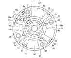
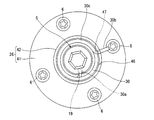
- FIG. 2 is a front view of the valve timing control device shown in FIG. 1 with a front plate removed. It is a front view of the valve timing control apparatus shown in FIG.
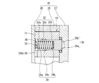
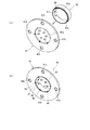
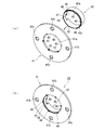
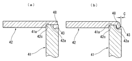
- FIG. 3 is a sectional view taken along line AA in FIG. 2. It is a perspective view of a front plate concerning a 1st embodiment of the present invention, and (a) is a figure showing the state after conclusion and (b) after conclusion. It is an expanded sectional view of the fastening part of the plate member and cylindrical member shown in FIG.
- valve timing control device for an internal combustion engine according to the present invention
- the apparatus is applied to an exhaust-side valve gear as in the conventional case.
- FIGS. 1 to 6 show a first embodiment of a valve timing control device for an internal combustion engine according to the present invention. As shown in FIG. are interposed between a sprocket 1 that is rotationally driven and a camshaft 2 that is provided so as to be relatively rotatable with respect to the sprocket 1, and the operation is controlled through predetermined hydraulic supply / discharge means 4. The relative rotational phase of 1 and 2 is converted.
- a plurality are provided on the outer peripheral portion of a substantially cylindrical rotor body 15 fixed to one end of the camshaft 2 so as to be integrally rotatable.
- a vane rotor 10 formed by projecting vanes 11 to 14 is provided integrally with the sprocket 1 and is disposed on the outer peripheral side of the vane rotor 10 so as to accommodate the vane rotor 10.
- one end 30a is fixed to the vane rotor 10 and the other end 30b is fixed to the housing 20, respectively.
- a torsion spring 30 that urges toward the advance side is interposed, and the camshaft 2 is moved immediately before the engine is stopped by the urging force of the torsion spring 30 so that no hydraulic pressure acts on any of the hydraulic chambers Ad and Re.
- the vane rotor 10 is biased to the advance side against a so-called alternating torque corresponding to the rotational force transmitted in the retard direction through the angle.
- the vane rotor 10 is externally fitted to one end portion of the camshaft 2 through a fitting portion 15a drilled on the inner end side (the side facing the camshaft 2) of the rotor body 15, and is formed to penetrate therethrough.
- the camshaft 2 is fastened to the camshaft 2 with a cam bolt 5 inserted through the insertion hole 15b.
- a later-described delay formed inside the camshaft 2 at a circumferential position adjacent to the base end of each of the vanes 11 to 14 on the inner surface of the rotor body 15 is provided.
- a plurality of retard side communication grooves 16a communicating the angle side oil passage 51 and the respective retard chambers Re are formed along the radial direction, and each of the retard side communication grooves 16a is used to supply and discharge hydraulic pressure.
- the hydraulic fluid guided from the means 4 through the inside of the camshaft 2 is introduced into each retarded angle chamber Re.
- a plurality of advance side communication grooves 16b are formed in the rotor body 15 to communicate later-described advance side oil passages 52 formed in the camshaft 2 and the respective advance chambers Ad.
- the hydraulic fluid guided from the hydraulic supply / discharge means 4 through the inside of the camshaft 2 is introduced into each advance chamber Ad through the advance side communication groove 16b.
- the outer end of the rotor body 15 (the end facing the front plate 26 described later) is used for seating the cam bolt 5 in the outer peripheral area of the insertion hole 15b.
- a flat bolt seating portion 17 is provided, and a spring seating portion 18, which is a circular groove provided for seating on the one end portion 30 a side of the torsion spring 30, is formed in the outer peripheral area of the bolt seating portion 17.
- the bolt seating portion 17 is set to a size close to the inner diameter, the outer diameter of which is slightly smaller than the inner diameter of the spring portion 30c that is a winding portion of the torsion spring 30, and the spring is attached to the outer peripheral portion of the spring.
- the part 30c is configured to fit.
- a first locking portion 19 used for locking and fixing the one end portion 30 a of the torsion spring 30 is provided on the end surface of the bolt seating portion 17.
- a notch is formed along the radial direction so as to open in the end face.
- the first locking portion 19 is formed to penetrate the spring seat portion 18 and the insertion hole 15b so as to be continuous with the spring seat portion 18 without a step, and one end portion 30a of the torsion spring 30 is a bolt seat portion. It is locked and fixed in the form of bending from the outer peripheral side of 17 to the center side.
- each of the vanes 11 to 14 is provided with a seal member S1 at the tip thereof along the thickness direction (axial direction of the rotor body 15).
- Each seal member S1 is in sliding contact with the inner peripheral surface of the housing 20, so that a space formed between the shoes 21 to 24 is separated by the pair of hydraulic chambers Ad and Re.
- only a predetermined vane 11 among the vanes 11 to 14 is set to have a larger circumferential width than the other vanes 12 to 14, and abuts against the adjacent shoes 21 and 24 at the time of the maximum relative rotation of the vane rotor 10. As a result, further rotation of the vane rotor 10 is restricted.
- a lock mechanism 31 for accommodating the phase of the vane rotor 10 when the engine is stopped, which will be described later, is accommodated.
- the lock mechanism 31 is slidably accommodated in a pin accommodating hole 34 formed through the wide vane 11 in the inner axial direction, and is pierced in a rear plate 27 described later.
- a substantially cylindrical lock pin 32 that restricts relative movement between the vane rotor 10 and the housing 20 by engaging with an engagement hole 35 provided, and an interposition between the lock pin 32 and a front plate 26 described later.
- the spring 33 mainly urges the lock pin 32 toward the rear plate 27 described later.
- the lock pin 32 is configured to have a stepped diameter reducing toward the tip side, and the pin receiving hole 34 is directed to the rear plate 27 side described later.
- the large diameter portion 32a on the proximal end side of the lock pin 32 is formed into a large diameter portion 34a of the pin accommodation hole 34, and the small diameter portion 32b on the distal end side of the lock pin 32 is constructed as a pin accommodation hole.
- the spring 33 is elastically mounted in the back pressure chamber 36 defined by the large diameter portion 34a of the pin receiving hole 34 by the large diameter portion 32a of the lock pin 32. Has been.
- the hydraulic pressure of the retarded angle chamber Re is introduced into the engagement hole 35 through a communication groove 37 formed in the inner surface of the wide vane 11 (the end surface facing the rear plate 27 described later).
- the lock pin 32 enters and exits the engagement hole 35 based on the hydraulic pressure in the retard chamber Re.
- a communication groove 38a for communicating the pin accommodation hole 34 and the spring seat portion 18 is formed in the outer surface of the wide vane 11 (the end surface facing the front plate 26 described later). That is, the opening of the communication groove 38a is closed by a front plate 26 described later, so that a slight gap between the outer peripheral surface of the large-diameter portion 32a of the lock pin 32 and the inner peripheral surface of the large-diameter portion 34a of the pin receiving hole 34
- a back pressure relief passage 38 is provided for discharging hydraulic oil leaking from the gap to the back pressure chamber 36 side.
- the housing 20 includes a housing main body 25 which is a substantially cylindrical driving rotary body in which the plurality of shoes 21 to 24 project from the inner periphery thereof, and the housing main body.
- the front plate 26 and the rear plate 27 close the front and rear opening ends of the front and rear 25, and the front plate 26 and the rear plate 27 are fastened together to the housing body 25 in the axial direction via four bolts 6 and nuts 7. Are connected together.
- Each of the shoes 21 to 24 is also provided with a seal member S2 along the thickness direction at the tip of each shoe, like the vanes 11 to 14, and each of the seal members S2 corresponds to the vane rotor 10.
- the hydraulic chambers Ad and Re as described above are separated between the shoes 21 to 24.
- the built-up portions 28 and 28 project from the base end side, and the vane rotor is provided.
- further rotation of the vane rotor 10 is restricted by making contact with the wide vane 11 while securing the hydraulic chambers Ad and Re between the circumferential directions of the wide vane 11. It is like that.
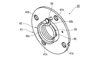
- the front plate 26 is configured in a relatively thin disk shape, and a plate member 41 having a fitting hole 41 a that is a circular hole penetratingly formed at the center position thereof.
- the cylindrical member 42 is provided separately from the plate member 41 so as to protrude from the outer end side edge of the fitting hole 41a and serves to accommodate and hold the spring portion 30c of the torsion spring 30.
- the cylindrical member 42 is integrally formed by caulking and fixing to the plate member 41.
- the plate member 41 is formed by press-molding a thin metal plate, and a plurality of bolt insertion holes 41b through which the bolts 6 are inserted at predetermined positions in the circumferential direction in the outer peripheral area of the fitting hole 41a. Is formed through.
- the fitting hole 41a is set to have an outer diameter larger than the outer diameter of the spring portion 30c of the torsion spring 30, and is described later formed in a cylindrical member 42 at a predetermined position in the circumferential direction on the inner end side hole edge.
- a plurality of locking grooves 43 (corresponding to the key grooves of the present invention) that are locked by the locking portions 44 are formed in cutouts.
- the cylindrical member 42 has a cylindrical shape formed with a predetermined plate thickness (thickness width) T2 smaller than that of the plate member 41, and a predetermined range of an inner end portion thereof is formed in a step-reduced shape, and
- the fitting portion 42a can be fitted into the fitting hole 41a.
- the fitting portion 42 a is set to a length that is slightly smaller than the plate thickness T ⁇ b> 1 of the plate member 41 and that the tip portion thereof faces each of the locking grooves 43.
- a minute gap C is formed between the tip and the inner surface of the plate member 41.
- a small axial gap C is formed between the tip of the fitting portion 42a and the rotor body 15 of the vane rotor 10 facing the fitting portion 42a when the apparatus is assembled.
- the cylindrical member 42 has a plurality of locking portions 44 (corresponding to the key constituent portions of the present invention) formed respectively at the distal end portions of the fitting portions 42a facing the locking grooves 43 by a caulking method described later.
- the locking grooves 43 are locked in a pressure contact state. That is, when the tip of the fitting portion 42 a is crushed, the meat (material) of the tip is pushed into the respective locking grooves 43, thereby being fastened and fixed to the plate member 41.
- the cylindrical member 42 is set so that the inner diameter thereof is substantially the same as the outer diameter of the spring seating portion 18, thereby forming a series of substantially smooth peripheral walls together with the spring seating portion 18.
- a series of spring accommodating portions 45 for accommodating the spring portion 30c of the torsion spring 30 are configured on the inner peripheral side of the spring guide.
- the outer end portion of the cylindrical member 42 is provided with a notch portion 46 formed by notching a part of the circumferential direction, and on the proximal end side thereof.
- a second locking portion 47 for locking and fixing the other end portion 30b of the torsion spring 30 is formed by cutting out a part along the circumferential direction. As described above, since the second locking portion 47 is formed in a groove shape that opens to the outer end portion of the cylindrical member 42, the torsion spring 30 can be assembled from the outside.
- the rear plate 27 is formed in a substantially disc shape, and is formed integrally with the sprocket 1 in such a manner that the sprocket 1 is provided on the outer peripheral portion thereof.
- An insertion hole 27a through which the camshaft 2 is inserted is formed through the center of the rear plate 27, and a plurality of bolt insertion holes 27b through which the bolts 6 are inserted are formed in the outer peripheral area of the insertion hole 27a. Is formed.
- a recess 27c is provided on the outer surface of the rear plate 27. The recess 27c can accommodate a nut 7 that is screwed with the bolts 6 to fasten the three members 25, 26, and 27.
- an engagement hole 35 is formed in the inner side surface of the rear plate 27 so as to engage with the lock pin 32 when the vane rotor 10 is at the most advanced angle position so as to restrain the rotation of the vane rotor 10. Yes. That is, as shown in FIG. 4, the engagement hole 35 has a first hole portion 35 a on the near side larger than the outer diameter of the distal end portion of the lock pin 32 and a second hole portion 35 b on the back side.
- the lock pin 32 is configured to have a stepped diameter that is smaller than the outer diameter of the distal end portion of the lock pin 32, and the lock pin 32 engages with the first hole 35a when the phase of the vane rotor 10 is in the most advanced state as described above. By doing so, the relative rotation of the vane rotor 10 with respect to the housing 20 is restricted.
- the hydraulic supply / discharge means 4 selectively supplies hydraulic pressure to the hydraulic chambers Ad and Re, or discharges hydraulic fluid in the hydraulic chambers Ad and Re.
- the retard angle side oil passage 51 connected to each of the retard angle side communication grooves 16 a, the advance angle side oil passage 52 connected to each of the advance angle side communication grooves 16 b, and one through a known solenoid valve 55.
- An oil pump 53 as a hydraulic pressure source for supplying hydraulic pressure to the oil passages 51 and 52 on the side, a drain passage 54 connected to the other oil passages 51 and 52 not connected to the oil pump 53 via the electromagnetic valve 55, and , Mainly consists of.
- the solenoid valve 55 is a two-way switching valve and selects connection between the oil passages 51, 52, the oil pump 53, and the drain passage 54 by a control signal from an electronic control unit (ECU) (not shown). Switching control.
- ECU electronice control unit
- the plate member 41 is formed by pressing a metal plate.
- the fitting holes 41a, the locking grooves 43, and the bolt insertion holes 41b are formed along with the molding. Further, in parallel with the molding of the plate member 41, the cylindrical member 42 is manufactured. Specifically, the fitting portion 42a and the second locking portion 47 are formed by cutting the metal tube into a predetermined length and then performing machining.
- the plate member 41 and the cylindrical member 42 manufactured in separate processes as described above are caulked (fastened) and fixed. That is, until the fitting portion 42a of the cylindrical member 42 is brought into contact with the fitting hole 41a from the outer surface side of the plate member 41, and the step portion 42c of the cylindrical member 42 is brought into contact with the outer end side edge of the fitting hole 41a. Insert. Thereafter, the fitting is performed in a state in which the rotation of the members 41 and 42 is performed (phase alignment) with the bolt insertion holes 41b and the second locking portions 47 through a jig (not shown). Of the portion 42 a, the portion that overlaps with each locking groove 43 is crimped by crushing each inner peripheral side edge of the fitting portion 42 a related to the overlapping with the tapered portion 60 a of the punch 60.
- the front plate 26 is configured by two members (two pieces) of the plate member 41 and the cylindrical member 42, an appropriate thickness width is provided for each of these members 41 and 42. It becomes possible to set. That is, for the cylindrical member 42 that does not require the plate thickness as much as the plate member 41, an unnecessary weight increase of the device can be avoided by setting the plate thickness to be smaller than that of the plate member 41, and the device is sufficiently lightweight. To be realized.
- the two-piece structure it is possible to eliminate the drawing process as compared with the case of the conventional one-piece structure, and the members 41 and 42 can be easily manufactured with higher accuracy. It becomes.
- the plate member 41 that requires high accuracy in relation to the clearance with the vane rotor 10 it is possible to increase the accuracy without increasing costs such as increasing the number of presses or increasing the accuracy of the die. There is also.
- a configuration is provided in which a minute gap C is provided between the tip of the fitting portion 42a of the cylindrical member 42 and the inner side surface of the plate member 41. It becomes possible to hold oil.
- the torsion spring 30 for urging the vane rotor 10 toward the advance side against the alternating torque immediately before the engine stops, in which no hydraulic pressure acts on any of the hydraulic chambers Ad and Re, that is, torsion.
- the second locking portion 47 is provided by a separate member by providing the cylindrical member 42 with the second locking portion 47 for locking and fixing the other end 30b of the torsion spring 30. Compared to the configuration, the number of parts can be reduced, and the productivity can be improved and the cost can be reduced.
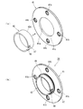
- FIGSecond Embodiment 7 and 8 show a second embodiment of the valve timing control device for an internal combustion engine according to the present invention, in which the plate member 41 and the cylindrical member 42 according to the first embodiment are caulked (fastened). The structure is changed.
- the basic configuration of the valve timing control device is the same as that of the first embodiment. Therefore, the same reference numerals are given to the same configurations as those of the first embodiment, and a specific description will be given. Is omitted.
- a plurality of claw portions 48 that can be locked in the respective locking grooves 43 at predetermined circumferential positions corresponding to the respective locking grooves 43 at the tips of the fitting portions 42 a of the cylindrical member 42. Is extended along the axial direction, and the claw portions 48 are bent and the claw portions 48 are engaged with the engagement grooves 43, so that the cylindrical member 42 is attached to the plate member 41. It is the composition concluded.
- the manufacturing process of the front plate 26 is basically the same as in the first embodiment. After the plate member 41 and the cylindrical member 42 are manufactured separately, the members 41 and 42 are caulked. (Fastening) Fix. In particular, in the present embodiment, the claw portions 48 are squeezed so as to crush the front end sides of the claw portions 48 projecting from the fitting portions 42 a of the cylindrical member 42, so that the claw portions 48 are engaged with the respective locking portions.
- the front plate 26 is completed when the plate member 41 and the cylindrical member 42 are fastened by being engaged with the groove 43 in a pressure contact state.
- this embodiment also differs from the first embodiment only in the fastening method of the members 41, 42, and basically has the same operational effects as the first embodiment. It is done.
- the fastening of both the members 41 and 42 is completed simply by pressing and bending the front end side of each claw portion 48 from the axial direction, so that compared with the first embodiment.
- the caulking work can be performed relatively easily.
- FIGS. 9 and 10 show a third embodiment of the valve timing control apparatus for an internal combustion engine according to the present invention, in which the plate member 41 and the cylindrical member 42 according to the first embodiment are caulked (fastened). The structure is changed.
- the basic configuration of the valve timing control device is the same as that of the first embodiment. Therefore, the same reference numerals are given to the same configurations as those of the first embodiment, and a specific description will be given. Is omitted.
- the inner end surface 42d of the cylindrical member 42 is configured to overlap with the hole edge 41c of the fitting hole 41a of the plate member 41 in the axial direction, and both the portions 41c and 42d are formed by friction welding. It becomes the structure joined.
- Reference numeral 49 in the figure indicates a curled portion formed by the friction welding.
- both the members 41 and 42 are set in the friction welding apparatus. Then join as described above.
- this embodiment also differs from the first embodiment only in the fixing method for the members 41 and 42, and basically has the same operational effects as the first embodiment. It is made.
- the entire inner end face 42d of the cylindrical member 42 is joined to the hole edge 41c of the fitting hole 41a of the plate member 41, both the members 41, There is an advantage that 42 can be fixed more firmly.
- the present invention is not limited to the configuration of each of the embodiments described above.
- the specific configuration of the housing 20, the vane rotor 10, the hydraulic supply / discharge means 4, etc. that are not directly related to the features of the present invention is included.
- the specific means for fixing the plate member 41 and the cylindrical member 42 related to the characteristics of the above any means can be adopted as long as the above-described effects of the present invention can be obtained. It can be freely changed according to the specifications and cost of the internal combustion engine.
- the configuration in which the second locking portion 47 that is locked by the other end portion 30b of the torsion spring 30 is provided integrally with the cylindrical member 42 has been described as an example.
- the configuration is limited to this configuration.
- a locking pin 50 which is a separate member, is erected on the plate member 41, and the other end 30 b is locked to the locking pin 50.
- the thickness width of the cylindrical member 42 can be set regardless of the urging force (torque) of the torsion spring 30, and the degree of freedom in setting the thickness width is increased. Can contribute to further weight reduction.
- the cylindrical member also serves as a locking portion of the torsion coil spring, it is not necessary to separately provide a locking portion of the torsion coil spring, which is used for improving productivity and reducing costs based on a reduction in the number of parts of the apparatus.
- the plate member and the cylindrical member can be tightened more firmly, and the durability of the apparatus is improved.
- valve timing control device for an internal combustion engine In the valve timing control device for an internal combustion engine according to claim 4, The valve timing control device for an internal combustion engine, wherein the key component is caulked by a punch having a taper.
- valve timing control device for an internal combustion engine (D) In the valve timing control device for an internal combustion engine according to (c), The valve timing control device for an internal combustion engine, wherein the plate member is molded by press working.
- valve timing control device for an internal combustion engine In the valve timing control device for an internal combustion engine according to (c), The valve timing control device for an internal combustion engine, wherein the cylindrical member is formed by machining after cutting a metal pipe into a predetermined length.
- valve timing control device for an internal combustion engine In the valve timing control device for an internal combustion engine according to claim 8, A valve timing control device for an internal combustion engine, wherein a predetermined minute gap is provided between a tip end of the claw portion after the pressing deformation and an inner side surface of the plate member.
- the base end of the key component is formed to be a step, The stepped portion is in contact with the outer end side hole edge of the through hole.
- Vane rotor (driven rotor) 11 to 14 ... Vane 20 ... Housing (drive rotating body) 21-24 ... Shoe 25 ... Housing body 26 ... Front plate 30 ... Torsion spring (torsion coil spring) 41 ... Plate member 41a ... Fitting hole (circular hole) 42 ... Cylindrical member 43 ... Locking groove (key groove) 44 ... Locking part (key component) Ad ... Advance chamber (Advance chamber) Re ... retarded angle chamber (retarded working chamber)
Landscapes
- Engineering & Computer Science (AREA)
- Mechanical Engineering (AREA)
- General Engineering & Computer Science (AREA)
- Valve Device For Special Equipments (AREA)
Abstract
Description
図1~図6は本発明に係る内燃機関のバルブタイミング制御装置の第1実施形態を表したもので、このバルブタイミング制御装置は、図1に示すように、図示外のクランクシャフトの回転力をもって回転駆動されるスプロケット1と、該スプロケット1に対して相対回転可能に設けられるカムシャフト2と、の間に介装され、所定の油圧給排手段4を通じて作動制御されることで、当該両者1,2の相対回転位相を変換するものである。
図7、図8は本発明に係る内燃機関のバルブタイミング制御装置の第2実施形態を示したものであって、前記第1実施形態に係るプレート部材41と円筒部材42とのかしめ(締結)構造の構成を変更したものである。なお、本実施形態においても、バルブタイミング制御装置の基本構成は前記第1実施形態と同様であるため、前記第1実施形態と同様の構成については同一の符号を付すことにより、具体的な説明については省略する。
図9、図10は本発明に係る内燃機関のバルブタイミング制御装置の第3実施形態を示したものであって、前記第1実施形態に係るプレート部材41と円筒部材42とのかしめ(締結)構造の構成を変更したものである。なお、本実施形態においても、バルブタイミング制御装置の基本構成は前記第1実施形態と同様であるため、前記第1実施形態と同様の構成については同一の符号を付すことにより、具体的な説明については省略する。
前記ねじりコイルばねの一端部は前記円筒部材に係止することを特徴とする内燃機関のバルブタイミング制御装置。
前記ねじりコイルばねの一端部は前記プレート部材に係止することを特徴とする内燃機関のバルブタイミング制御装置。
前記キー構成部は、テーパを有するポンチによりかしめられていることを特徴とする内燃機関のバルブタイミング制御装置。
前記プレート部材は、プレス加工により成型されることを特徴とする内燃機関のバルブタイミング制御装置。
前記円筒部材は、金属管を所定の長さに切断した後に機械加工によって形成されることを特徴とする内燃機関のバルブタイミング制御装置。
前記押圧変形した後の前記爪部の先端と前記プレート部材の内側面との間には、所定の微小隙間が設けられていることを特徴とする内燃機関のバルブタイミング制御装置。
前記爪部は、複数設けられていることを特徴とする内燃機関のバルブタイミング制御装置。
前記爪部は、前記円形孔の内端縁に対をなすように配置されていることを特徴とする内燃機関のバルブタイミング制御装置。
前記キー構成部の基端部は段部となるように形成され、
該段部は前記貫通孔の外端側孔縁に当接していることを特徴とする締結構造。
前記押圧変形した後の前記キー構成部の先端と前記第1部材の内側面との間には、所定の微小隙間が設けられていることを特徴とする締結構造。
11~14…ベーン
20…ハウジング(駆動回転体)
21~24…シュー
25…ハウジング本体
26…フロントプレート
30…トーションスプリング(ねじりコイルばね)
41…プレート部材
41a…嵌合孔(円形孔)
42…円筒部材
43…係止溝(キー溝)
44…係止部(キー構成部)
Ad…進角室(進角作動室)
Re…遅角室(遅角作動室)
Claims (20)
- クランクシャフトから回転力が伝達される駆動回転体と、
前記駆動回転体に対して所定角度範囲内で相対回転可能に設けられた従動回転体と、
前記従動回転体を回転方向の一方側に付勢するねじりコイルばねの一端が係止するフロントプレートと、
を備え、
前記フロントプレートは、
前記駆動回転体の一端を閉塞するように設けられ、中央位置に円形孔が貫通形成されたプレート部材と、
前記プレート部材の外側面から突出するように設けられ、該プレート部材に固定される円筒部材と、
を有することを特徴とする内燃機関のバルブタイミング制御装置。 - 請求項1に記載の内燃機関のバルブタイミング制御装置おいて、
前記円形孔の内端縁にはキー溝が形成され、
前記円筒部材は、一端部が前記円形孔の外端側から嵌挿され、かつ、該一端部の端縁に形成されたキー構成部が前記キー溝と係合するように押圧変形されることによって前記プレート部材に締結固定されることを特徴とする内燃機関のバルブタイミング制御装置。 - 請求項2に記載の内燃機関のバルブタイミング制御装置おいて、
前記キー構成部の基端部は段部となるように形成され、
該段部は前記円形孔の外端側孔縁に当接していることを特徴とする内燃機関のバルブタイミング制御装置。 - 請求項3に記載の内燃機関のバルブタイミング制御装置おいて、
前記押圧変形した後の前記キー構成部の先端と前記プレート部材の内側面との間には、所定の微小隙間が設けられていることを特徴とする内燃機関のバルブタイミング制御装置 - 請求項4に記載の内燃機関のバルブタイミング制御装置おいて、
前記円筒部材の厚さ幅は、前記プレート部材の厚さ幅よりも小さく設定されていることを特徴とする内燃機関のバルブタイミング制御装置。 - 請求項5に記載の内燃機関のバルブタイミング制御装置おいて、
前記ねじりコイルばねの一端部は前記円筒部材に係止することを特徴とする内燃機関のバルブタイミング制御装置。 - 請求項5に記載の内燃機関のバルブタイミング制御装置において、
前記ねじりコイルばねの一端部は前記プレート部材に係止することを特徴とする内燃機関のバルブタイミング制御装置。 - 請求項4に記載の内燃機関のバルブタイミング制御装置において、
前記キー構成部は、テーパを有するポンチによりかしめられていることを特徴とする内燃機関のバルブタイミング制御装置。 - 請求項8に記載の内燃機関のバルブタイミング制御装置において、
前記プレート部材は、プレス加工により成型されることを特徴とする内燃機関のバルブタイミング制御装置。 - 請求項8に記載の内燃機関のバルブタイミング制御装置において、
前記円筒部材は、金属管を所定の長さに切断した後に機械加工によって形成されることを特徴とする内燃機関のバルブタイミング制御装置。 - 請求項4に記載の内燃機関のバルブタイミング制御装置において、
前記キー溝及びこれに対応する前記キー構成部は、複数設けられていることを特徴とする内燃機関のバルブタイミング制御装置。 - 請求項11に記載の内燃機関のバルブタイミング制御装置において、
前記キー溝及びこれに対応する前記キー構成部は、前記円形孔の内端縁に対をなすように配置されていることを特徴とする内燃機関のバルブタイミング制御装置。 - 請求項1に記載の内燃機関のバルブタイミング制御装置において、
前記円筒部材は、該円筒部材の一端縁から突設された複数の爪部を曲折変形させることによって前記プレート部材に固定されることを特徴とする内燃機関のバルブタイミング制御装置。 - 請求項13に記載の内燃機関のバルブタイミング制御装置において、
前記押圧変形した後の前記爪部の先端と前記プレート部材の内側面との間には、所定の微小隙間が設けられていることを特徴とする内燃機関のバルブタイミング制御装置。 - 請求項14に記載の内燃機関のバルブタイミング制御装置において、
前記爪部は、複数設けられていることを特徴とする内燃機関のバルブタイミング制御装置。 - 請求項15に記載の内燃機関のバルブタイミング制御装置において、
前記爪部は、前記円形孔の内端縁に対をなすように配置されていることを特徴とする内燃機関のバルブタイミング制御装置。 - 請求項1に記載の内燃機関のバルブタイミング制御装置において、
前記円筒部材は、摩擦圧接によって前記プレート部材に固定されることを特徴とする内燃機関のバルブタイミング制御装置。 - 中央位置に貫通孔が設けられると共に、該貫通孔の内端縁にキー溝が設けられた第1部材と、
前記第1部材の外側面から突出するように設けられ、基端部にキー構成部が形成された筒状の第2部材と、
を備え、
前記キー構成部を前記キー溝と係合するように押圧変形させることによって前記第2部材を前記第1部材に締結固定することを特徴とする締結構造。 - 請求項18に記載の締結構造において、
前記キー構成部の基端部は段部となるように形成され、
該段部は前記貫通孔の外端側孔縁に当接していることを特徴とする締結構造。 - 請求項19に記載の締結構造において、
前記押圧変形した後の前記キー構成部の先端と前記第1部材の内側面との間には、所定の微小隙間が設けられていることを特徴とする締結構造。
Priority Applications (2)
| Application Number | Priority Date | Filing Date | Title |
|---|---|---|---|
| JP2015537962A JP6109949B2 (ja) | 2013-09-20 | 2014-09-18 | 内燃機関のバルブタイミング制御装置 |
| US14/917,706 US9951660B2 (en) | 2013-09-20 | 2014-09-18 | Valve timing control device for internal combustion engine, and fastening structure |
Applications Claiming Priority (2)
| Application Number | Priority Date | Filing Date | Title |
|---|---|---|---|
| JP2013195043 | 2013-09-20 | ||
| JP2013-195043 | 2013-09-20 |
Publications (1)
| Publication Number | Publication Date |
|---|---|
| WO2015041280A1 true WO2015041280A1 (ja) | 2015-03-26 |
Family
ID=52688927
Family Applications (1)
| Application Number | Title | Priority Date | Filing Date |
|---|---|---|---|
| PCT/JP2014/074654 Ceased WO2015041280A1 (ja) | 2013-09-20 | 2014-09-18 | 内燃機関のバルブタイミング制御装置及び締結構造 |
Country Status (3)
| Country | Link |
|---|---|
| US (1) | US9951660B2 (ja) |
| JP (1) | JP6109949B2 (ja) |
| WO (1) | WO2015041280A1 (ja) |
Cited By (2)
| Publication number | Priority date | Publication date | Assignee | Title |
|---|---|---|---|---|
| US11015491B2 (en) | 2016-08-24 | 2021-05-25 | Borgwarner Inc. | Mechanism for locking a variable cam timing device |
| WO2021161499A1 (ja) * | 2020-02-14 | 2021-08-19 | 三菱電機株式会社 | バルブタイミング調整装置 |
Families Citing this family (4)
| Publication number | Priority date | Publication date | Assignee | Title |
|---|---|---|---|---|
| JP2018168776A (ja) * | 2017-03-30 | 2018-11-01 | アイシン精機株式会社 | 弁開閉時期制御装置 |
| DE102017109006A1 (de) * | 2017-04-27 | 2018-10-31 | ECO Holding 1 GmbH | Nockenwellenversteller |
| CN111183273A (zh) * | 2017-11-28 | 2020-05-19 | 舍弗勒技术股份两合公司 | 用于凸轮轴相位器的盖元件和凸轮轴相位器 |
| CN113858067A (zh) * | 2021-09-09 | 2021-12-31 | 安徽安荣新能源科技有限公司 | 一种调节夹持压力的降压阀生产用多工位夹具 |
Citations (7)
| Publication number | Priority date | Publication date | Assignee | Title |
|---|---|---|---|---|
| JPS4839850A (ja) * | 1972-01-14 | 1973-06-12 | ||
| JPS56102326A (en) * | 1980-01-17 | 1981-08-15 | Hitachi Powdered Metals Co Ltd | Joining method of metal-made member |
| JPH0742721A (ja) * | 1993-08-03 | 1995-02-10 | Isuzu Motors Ltd | 溶接ナット並びに溶接ナットの接合方法及び溶接ナット接合用電極装置 |
| JP2001098909A (ja) * | 1999-09-30 | 2001-04-10 | Aisin Seiki Co Ltd | 弁開閉時期制御装置 |
| JP2005240651A (ja) * | 2004-02-25 | 2005-09-08 | Aisin Seiki Co Ltd | 弁開閉時期制御装置 |
| JP2005325749A (ja) * | 2004-05-13 | 2005-11-24 | Toyota Motor Corp | 内燃機関のバルブタイミング可変装置 |
| JP2005325758A (ja) * | 2004-05-13 | 2005-11-24 | Denso Corp | バルブタイミング調整装置 |
Family Cites Families (1)
| Publication number | Priority date | Publication date | Assignee | Title |
|---|---|---|---|---|
| US8127728B2 (en) * | 2008-03-21 | 2012-03-06 | Delphi Technologies, Inc. | Vane-type cam phaser having dual rotor bias springs |
-
2014
- 2014-09-18 US US14/917,706 patent/US9951660B2/en not_active Expired - Fee Related
- 2014-09-18 JP JP2015537962A patent/JP6109949B2/ja not_active Expired - Fee Related
- 2014-09-18 WO PCT/JP2014/074654 patent/WO2015041280A1/ja not_active Ceased
Patent Citations (7)
| Publication number | Priority date | Publication date | Assignee | Title |
|---|---|---|---|---|
| JPS4839850A (ja) * | 1972-01-14 | 1973-06-12 | ||
| JPS56102326A (en) * | 1980-01-17 | 1981-08-15 | Hitachi Powdered Metals Co Ltd | Joining method of metal-made member |
| JPH0742721A (ja) * | 1993-08-03 | 1995-02-10 | Isuzu Motors Ltd | 溶接ナット並びに溶接ナットの接合方法及び溶接ナット接合用電極装置 |
| JP2001098909A (ja) * | 1999-09-30 | 2001-04-10 | Aisin Seiki Co Ltd | 弁開閉時期制御装置 |
| JP2005240651A (ja) * | 2004-02-25 | 2005-09-08 | Aisin Seiki Co Ltd | 弁開閉時期制御装置 |
| JP2005325749A (ja) * | 2004-05-13 | 2005-11-24 | Toyota Motor Corp | 内燃機関のバルブタイミング可変装置 |
| JP2005325758A (ja) * | 2004-05-13 | 2005-11-24 | Denso Corp | バルブタイミング調整装置 |
Cited By (2)
| Publication number | Priority date | Publication date | Assignee | Title |
|---|---|---|---|---|
| US11015491B2 (en) | 2016-08-24 | 2021-05-25 | Borgwarner Inc. | Mechanism for locking a variable cam timing device |
| WO2021161499A1 (ja) * | 2020-02-14 | 2021-08-19 | 三菱電機株式会社 | バルブタイミング調整装置 |
Also Published As
| Publication number | Publication date |
|---|---|
| US20160222835A1 (en) | 2016-08-04 |
| JPWO2015041280A1 (ja) | 2017-03-02 |
| US9951660B2 (en) | 2018-04-24 |
| JP6109949B2 (ja) | 2017-04-05 |
Similar Documents
| Publication | Publication Date | Title |
|---|---|---|
| JP6109949B2 (ja) | 内燃機関のバルブタイミング制御装置 | |
| US20120285407A1 (en) | Variable valve timing control apparatus of internal combustion engine | |
| US9657608B2 (en) | Variable valve timing device and method of assembling same | |
| US9151187B2 (en) | Valve timing control apparatus for internal combustion engine | |
| US20080022952A1 (en) | Valve timing control apparatus and its assembling method | |
| US20160273417A1 (en) | Valve timing control device for internal combustion engine | |
| JP6259130B2 (ja) | 内燃機関のバルブタイミング制御装置 | |
| JP2008240735A (ja) | 内燃機関のバルブタイミング制御装置 | |
| US10280814B2 (en) | Valve opening/closing timing control apparatus | |
| JP5198395B2 (ja) | 内燃機関のバルブタイミング制御装置 | |
| JP4126325B2 (ja) | 内燃機関のバルブタイミング制御装置用ハウジング | |
| JP7200914B2 (ja) | バルブタイミング調整装置 | |
| US20170138225A1 (en) | Valve opening/closing timing control apparatus | |
| JP2006291944A (ja) | 弁開閉時期制御装置 | |
| JP5859751B2 (ja) | 内燃機関のバルブタイミング制御装置及びこの装置の製造方法 | |
| JP2010190144A (ja) | バルブタイミング調整装置及びその製造方法 | |
| JP2013256899A (ja) | 内燃機関の可変動弁装置 | |
| JP4304219B2 (ja) | 内燃機関のバルブタイミング制御装置及びその組立方法 | |
| JP6533322B2 (ja) | 内燃機関のバルブタイミング制御装置 | |
| JP4083788B2 (ja) | 内燃機関のバルブタイミング制御装置用ハウジング | |
| US10337358B2 (en) | Valve timing control apparatus for internal combustion engine | |
| US20200049033A1 (en) | Valve timing control device for internal combustion engine | |
| JP2018182034A (ja) | 電磁アクチュエータと電磁弁 | |
| JP2017089518A (ja) | 弁開閉時期制御装置 | |
| CN107636265A (zh) | 内燃机的气门正时控制装置以及使用该气门正时控制装置的内燃机 |
Legal Events
| Date | Code | Title | Description |
|---|---|---|---|
| 121 | Ep: the epo has been informed by wipo that ep was designated in this application |
Ref document number: 14845672 Country of ref document: EP Kind code of ref document: A1 |
|
| ENP | Entry into the national phase |
Ref document number: 2015537962 Country of ref document: JP Kind code of ref document: A |
|
| WWE | Wipo information: entry into national phase |
Ref document number: 14917706 Country of ref document: US |
|
| NENP | Non-entry into the national phase |
Ref country code: DE |
|
| 122 | Ep: pct application non-entry in european phase |
Ref document number: 14845672 Country of ref document: EP Kind code of ref document: A1 |