WO2015041017A1 - 二次電池 - Google Patents
二次電池 Download PDFInfo
- Publication number
- WO2015041017A1 WO2015041017A1 PCT/JP2014/072384 JP2014072384W WO2015041017A1 WO 2015041017 A1 WO2015041017 A1 WO 2015041017A1 JP 2014072384 W JP2014072384 W JP 2014072384W WO 2015041017 A1 WO2015041017 A1 WO 2015041017A1
- Authority
- WO
- WIPO (PCT)
- Prior art keywords
- secondary battery
- container
- extensible sheet
- negative electrode
- positive electrode
- Prior art date
- Legal status (The legal status is an assumption and is not a legal conclusion. Google has not performed a legal analysis and makes no representation as to the accuracy of the status listed.)
- Ceased
Links
Images


Classifications
-
- H—ELECTRICITY
- H01—ELECTRIC ELEMENTS
- H01M—PROCESSES OR MEANS, e.g. BATTERIES, FOR THE DIRECT CONVERSION OF CHEMICAL ENERGY INTO ELECTRICAL ENERGY
- H01M50/00—Constructional details or processes of manufacture of the non-active parts of electrochemical cells other than fuel cells, e.g. hybrid cells
- H01M50/10—Primary casings; Jackets or wrappings
- H01M50/116—Primary casings; Jackets or wrappings characterised by the material
- H01M50/124—Primary casings; Jackets or wrappings characterised by the material having a layered structure
-
- H—ELECTRICITY
- H01—ELECTRIC ELEMENTS
- H01M—PROCESSES OR MEANS, e.g. BATTERIES, FOR THE DIRECT CONVERSION OF CHEMICAL ENERGY INTO ELECTRICAL ENERGY
- H01M50/00—Constructional details or processes of manufacture of the non-active parts of electrochemical cells other than fuel cells, e.g. hybrid cells
- H01M50/10—Primary casings; Jackets or wrappings
- H01M50/116—Primary casings; Jackets or wrappings characterised by the material
- H01M50/117—Inorganic material
- H01M50/119—Metals
-
- H—ELECTRICITY
- H01—ELECTRIC ELEMENTS
- H01M—PROCESSES OR MEANS, e.g. BATTERIES, FOR THE DIRECT CONVERSION OF CHEMICAL ENERGY INTO ELECTRICAL ENERGY
- H01M50/00—Constructional details or processes of manufacture of the non-active parts of electrochemical cells other than fuel cells, e.g. hybrid cells
- H01M50/10—Primary casings; Jackets or wrappings
- H01M50/116—Primary casings; Jackets or wrappings characterised by the material
- H01M50/121—Organic material
-
- H—ELECTRICITY
- H01—ELECTRIC ELEMENTS
- H01M—PROCESSES OR MEANS, e.g. BATTERIES, FOR THE DIRECT CONVERSION OF CHEMICAL ENERGY INTO ELECTRICAL ENERGY
- H01M50/00—Constructional details or processes of manufacture of the non-active parts of electrochemical cells other than fuel cells, e.g. hybrid cells
- H01M50/10—Primary casings; Jackets or wrappings
- H01M50/116—Primary casings; Jackets or wrappings characterised by the material
- H01M50/124—Primary casings; Jackets or wrappings characterised by the material having a layered structure
- H01M50/126—Primary casings; Jackets or wrappings characterised by the material having a layered structure comprising three or more layers
-
- H—ELECTRICITY
- H01—ELECTRIC ELEMENTS
- H01M—PROCESSES OR MEANS, e.g. BATTERIES, FOR THE DIRECT CONVERSION OF CHEMICAL ENERGY INTO ELECTRICAL ENERGY
- H01M50/00—Constructional details or processes of manufacture of the non-active parts of electrochemical cells other than fuel cells, e.g. hybrid cells
- H01M50/10—Primary casings; Jackets or wrappings
- H01M50/131—Primary casings; Jackets or wrappings characterised by physical properties, e.g. gas permeability, size or heat resistance
-
- H—ELECTRICITY
- H01—ELECTRIC ELEMENTS
- H01M—PROCESSES OR MEANS, e.g. BATTERIES, FOR THE DIRECT CONVERSION OF CHEMICAL ENERGY INTO ELECTRICAL ENERGY
- H01M50/00—Constructional details or processes of manufacture of the non-active parts of electrochemical cells other than fuel cells, e.g. hybrid cells
- H01M50/40—Separators; Membranes; Diaphragms; Spacing elements inside cells
- H01M50/471—Spacing elements inside cells other than separators, membranes or diaphragms; Manufacturing processes thereof
- H01M50/474—Spacing elements inside cells other than separators, membranes or diaphragms; Manufacturing processes thereof characterised by their position inside the cells
-
- H—ELECTRICITY
- H01—ELECTRIC ELEMENTS
- H01M—PROCESSES OR MEANS, e.g. BATTERIES, FOR THE DIRECT CONVERSION OF CHEMICAL ENERGY INTO ELECTRICAL ENERGY
- H01M2200/00—Safety devices for primary or secondary batteries
-
- H—ELECTRICITY
- H01—ELECTRIC ELEMENTS
- H01M—PROCESSES OR MEANS, e.g. BATTERIES, FOR THE DIRECT CONVERSION OF CHEMICAL ENERGY INTO ELECTRICAL ENERGY
- H01M2220/00—Batteries for particular applications
- H01M2220/20—Batteries in motive systems, e.g. vehicle, ship, plane
-
- Y—GENERAL TAGGING OF NEW TECHNOLOGICAL DEVELOPMENTS; GENERAL TAGGING OF CROSS-SECTIONAL TECHNOLOGIES SPANNING OVER SEVERAL SECTIONS OF THE IPC; TECHNICAL SUBJECTS COVERED BY FORMER USPC CROSS-REFERENCE ART COLLECTIONS [XRACs] AND DIGESTS
- Y02—TECHNOLOGIES OR APPLICATIONS FOR MITIGATION OR ADAPTATION AGAINST CLIMATE CHANGE
- Y02E—REDUCTION OF GREENHOUSE GAS [GHG] EMISSIONS, RELATED TO ENERGY GENERATION, TRANSMISSION OR DISTRIBUTION
- Y02E60/00—Enabling technologies; Technologies with a potential or indirect contribution to GHG emissions mitigation
- Y02E60/10—Energy storage using batteries
Definitions
- the present invention relates to a chargeable / dischargeable secondary battery.
- Secondary batteries that can be charged and discharged are used in hybrid cars, electric cars, or electric assist bicycles.
- the secondary battery is configured by, for example, a battery element in which a plurality of positive electrodes and a plurality of negative electrodes are stacked via a separator made of polyethylene, polypropylene, or the like, and housed in a container together with an electrolytic solution.
- the secondary battery configured as described above, for example, when a sharp metal piece such as a nail pierces the container, a short circuit occurs between the positive electrode and the negative electrode due to the metal piece, and an excessive current flows. There is a risk that the battery will generate heat and the battery will explode or ignite.
- Patent Document 1 discloses a method of preventing a short circuit from occurring between the positive electrode and the negative electrode when a metal piece pierces the battery container. Specifically, by arranging a polymer sheet having an elongation rate of 1% or more on the outer peripheral surface of the container, when the metal piece pierces the container, the polymer sheet extends along the metal piece and Can cover the sides. As a result, since a polymer sheet with extremely low electrical conductivity is interposed between the positive electrode and the negative electrode, it is possible to prevent a short circuit from occurring between the positive electrode and the negative electrode, and to prevent the battery from bursting or igniting. Can be prevented.
- Patent Document 1 since a polymer sheet having extremely low electrical conductivity is disposed on the outer peripheral surface of the container, when the metal piece pierces the container, the metal piece is inserted between the positive electrode and the negative electrode. A short circuit is prevented.
- the battery element composed of the positive electrode and the negative electrode is in a state where energy is accumulated. Therefore, if the polymer sheet breaks in any moment, a short circuit occurs between the positive electrode and the negative electrode through the metal piece, an excessive current flows instantaneously, the battery generates heat, and the battery may explode or ignite There is.
- An object of the present invention is to provide a secondary battery that solves the problem that a container may rupture or ignite when a metal piece pierces the container.
- the secondary battery of the present invention is at least partially surrounded by an extensible sheet having an extensibility of surface resistivity of 10 ⁇ 2 ⁇ / sq to 10 10 ⁇ / sq, and is housed in a container together with the electrolyte. And a battery element in which a positive electrode and a negative electrode are laminated or wound with a separator interposed therebetween.
- the energy stored in the battery element is gradually released, it is possible to prevent the secondary battery from being ruptured or ignited.
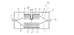
- FIG. 1 is a schematic cross-sectional view of an embodiment of a secondary battery according to the present invention. It is the schematic which shows a mode when a metal piece pierces the secondary battery of this invention. It is a schematic sectional drawing of other embodiment of the secondary battery which concerns on this invention.
- FIG. 1 is a schematic configuration diagram of an embodiment of a secondary battery of the present invention.
- FIG. 1 shows a secondary battery having a battery element in which a positive electrode and a negative electrode are stacked with a separator interposed therebetween.
- the present invention is not limited to this, and can also be applied to a secondary battery having a battery element in which a positive electrode and a negative electrode are wound via a separator.
- a positive electrode 1 and a negative electrode 2 are laminated via a separator 3 to form a battery element 4.
- the battery element 4 is accommodated in the container 5 together with the electrolytic solution.
- One end of the positive electrode tab 6 is located in the container 5 and connected to each positive electrode 1, and the other end of the positive electrode tab 6 is located outside the container 5.
- One end of the negative electrode tab 7 is located in the container 5 and connected to each negative electrode 2, and the other end of the negative electrode tab 7 is located outside the container 5.
- the positive electrode tab 6 and the negative electrode tab 7 are located on two opposing surfaces of the container 5, but the positive electrode tab 6 and the negative electrode tab 7 may be located in the same direction.
- the extensible sheet 11 is disposed so as to cover the battery element 4.
- the extensible sheet 11 in the present invention is characterized by having a surface resistivity of 10 ⁇ 2 ⁇ / sq to 10 10 ⁇ / sq and an elongation of 10% or more.
- Examples of the extensible sheet 11 include a polyurethane film and cellophane.
- the extensible sheet 11 has extensibility. Therefore, the metal piece 20 extends along the metal piece 20 that penetrates the container 5. Can be covered. As a result, the extensible sheet 11 is interposed between the positive electrode 1 and the negative electrode 2.
- Patent Document 1 which is an example of the related art described above, a polymer sheet having extremely low electrical conductivity was used. However, the extensible sheet 11 of the present invention has a resistance of 10 ⁇ 2 ⁇ / sq to 10 10 ⁇ / sq. Has surface resistivity.
- the surface resistivity is on the order of 10 ⁇ 3
- the surface resistivity is on the order of 10 11 or more. That is, unlike the polymer sheet of Patent Document 1, the extensible sheet of the present invention has a little electrical conductivity, so that a small amount of electricity can flow. Therefore, the extensible sheet 11 is brought into contact with the positive electrode 1 and the negative electrode 2 by the metal piece 20, and a short circuit is caused by the extensible sheet 11, and a short circuit current flows through the extensible sheet 11, thereby The energy held by the element 4 is gradually released. Since the energy held by the battery element 4 is gradually released, the secondary battery generates heat, and the risk of explosion or ignition is suppressed.
- the extensible sheet 11 is disposed between the battery element 4 and the inner wall surface of the container 5 so as to cover the battery element 4, but for example, as shown in FIG.
- the extensible sheet 11 can also be arranged so as to cover the outside.
- the container 5 can be comprised with the laminate film which covers both surfaces of metal layers, such as aluminum foil, with a resin layer, and at least one layer can also be comprised with the extensible sheet
Landscapes
- Chemical & Material Sciences (AREA)
- Chemical Kinetics & Catalysis (AREA)
- Electrochemistry (AREA)
- General Chemical & Material Sciences (AREA)
- Inorganic Chemistry (AREA)
- Connection Of Batteries Or Terminals (AREA)
- Secondary Cells (AREA)
- Sealing Battery Cases Or Jackets (AREA)
- Cell Separators (AREA)
Abstract
Description
2 負極電極
3 セパレータ
4 電池要素
5 容器
10 二次電池
11 伸長性シート
Claims (5)
- 表面抵抗率が10-2Ω/sq~1010Ω/sqの伸長性を有する伸長性シートによって少なくとも一部が囲まれており、電解液とともに容器に収容された、正極電極と負極電極とがセパレータを介して積層または巻回した電池要素を有する、二次電池。
- 前記伸長性シートは前記電池要素と前記容器の内壁面との間に配置されている、請求項1に記載の二次電池。
- 前記伸長性シートは、前記容器の外側を覆うように配置されている、請求項1に記載の二次電池。
- 前記容器は複数の層で構成されるラミネートフィルムからなり、前記複数の層のうちの少なくとも一層が、前記伸長性シートからなる、請求項1に記載の二次電池。
- 前記伸長性シートの伸び率が10%以上である、請求項1から4のいずれか1項に記載の二次電池。
Priority Applications (2)
| Application Number | Priority Date | Filing Date | Title |
|---|---|---|---|
| US15/023,091 US9871238B2 (en) | 2013-09-20 | 2014-08-27 | Secondary battery |
| JP2015537621A JPWO2015041017A1 (ja) | 2013-09-20 | 2014-08-27 | 二次電池 |
Applications Claiming Priority (2)
| Application Number | Priority Date | Filing Date | Title |
|---|---|---|---|
| JP2013195368 | 2013-09-20 | ||
| JP2013-195368 | 2013-09-20 |
Publications (1)
| Publication Number | Publication Date |
|---|---|
| WO2015041017A1 true WO2015041017A1 (ja) | 2015-03-26 |
Family
ID=52688672
Family Applications (1)
| Application Number | Title | Priority Date | Filing Date |
|---|---|---|---|
| PCT/JP2014/072384 Ceased WO2015041017A1 (ja) | 2013-09-20 | 2014-08-27 | 二次電池 |
Country Status (3)
| Country | Link |
|---|---|
| US (1) | US9871238B2 (ja) |
| JP (1) | JPWO2015041017A1 (ja) |
| WO (1) | WO2015041017A1 (ja) |
Families Citing this family (1)
| Publication number | Priority date | Publication date | Assignee | Title |
|---|---|---|---|---|
| WO2020072838A1 (en) * | 2018-10-03 | 2020-04-09 | The Regents Of The University Of California | Resistive polymer membranes for energy storage devices |
Citations (4)
| Publication number | Priority date | Publication date | Assignee | Title |
|---|---|---|---|---|
| JPH10308198A (ja) * | 1997-05-06 | 1998-11-17 | Asahi Chem Ind Co Ltd | 電池外装体用積層フィルム |
| JP2000021386A (ja) * | 1998-07-06 | 2000-01-21 | Japan Storage Battery Co Ltd | 電 池 |
| JP2002151159A (ja) * | 2000-09-01 | 2002-05-24 | Nisshinbo Ind Inc | リチウム系電池 |
| WO2013027296A1 (ja) * | 2011-08-25 | 2013-02-28 | 日立ビークルエナジー株式会社 | リチウムイオン二次電池およびその製造方法 |
Family Cites Families (4)
| Publication number | Priority date | Publication date | Assignee | Title |
|---|---|---|---|---|
| JP3178586B2 (ja) | 1995-01-27 | 2001-06-18 | 旭化成株式会社 | 非水系電池 |
| JP3822550B2 (ja) | 2001-12-28 | 2006-09-20 | Tdk株式会社 | リチウム二次電池 |
| WO2006046615A1 (ja) * | 2004-10-29 | 2006-05-04 | Dai Nippon Printing Co., Ltd. | 積層体及び二次電池 |
| KR101014817B1 (ko) * | 2007-12-14 | 2011-02-14 | 주식회사 엘지화학 | 안전 부재를 포함하고 있는 스택/폴딩형 전극조립체 및그것의 제조방법 |
-
2014
- 2014-08-27 US US15/023,091 patent/US9871238B2/en active Active
- 2014-08-27 WO PCT/JP2014/072384 patent/WO2015041017A1/ja not_active Ceased
- 2014-08-27 JP JP2015537621A patent/JPWO2015041017A1/ja active Pending
Patent Citations (4)
| Publication number | Priority date | Publication date | Assignee | Title |
|---|---|---|---|---|
| JPH10308198A (ja) * | 1997-05-06 | 1998-11-17 | Asahi Chem Ind Co Ltd | 電池外装体用積層フィルム |
| JP2000021386A (ja) * | 1998-07-06 | 2000-01-21 | Japan Storage Battery Co Ltd | 電 池 |
| JP2002151159A (ja) * | 2000-09-01 | 2002-05-24 | Nisshinbo Ind Inc | リチウム系電池 |
| WO2013027296A1 (ja) * | 2011-08-25 | 2013-02-28 | 日立ビークルエナジー株式会社 | リチウムイオン二次電池およびその製造方法 |
Also Published As
| Publication number | Publication date |
|---|---|
| JPWO2015041017A1 (ja) | 2017-03-02 |
| US20160233472A1 (en) | 2016-08-11 |
| US9871238B2 (en) | 2018-01-16 |
Similar Documents
| Publication | Publication Date | Title |
|---|---|---|
| JP7041810B2 (ja) | ベンティングガスを用いてコネクターを破断する構造を有するバッテリーモジュール | |
| JP6780109B2 (ja) | 安全性が向上したバッテリーモジュール及びバッテリーパック | |
| EP2293367B1 (en) | Rechargeable secondary battery having improved safety against puncture and collapse | |
| JP2024096240A (ja) | 蓄電モジュール | |
| JP6678989B2 (ja) | 非水電解液二次電池セル及びこれを用いた組電池 | |
| JP5314665B2 (ja) | 電池 | |
| JP6472539B2 (ja) | 電極リード及びこれを含む二次電池 | |
| KR102097084B1 (ko) | 파우치형 이차전지 및 이를 포함하는 배터리 모듈 | |
| US20140065453A1 (en) | Electrochemical energy storage cell and electrochemical energy storage device comprising at least one such electrochemical energy storage cell | |
| JP2010086753A (ja) | 蓄電デバイス | |
| JP2017076601A (ja) | バッテリーセル | |
| JP2013537694A (ja) | 少なくとも1つの圧力軽減装置を有する電気化学的セル | |
| KR20090064041A (ko) | 신규한 실링부 구조를 포함하는 이차전지 | |
| KR20130014253A (ko) | 안전성이 향상된 이차전지 및 이를 이용한 중대형 전지팩 | |
| JP5821652B2 (ja) | 蓄電素子モジュール | |
| KR20150062820A (ko) | 파우치형 이차전지 | |
| KR20140137603A (ko) | 파우치형 외장재 | |
| JP2016039094A (ja) | 積層型電池及び電池モジュール | |
| US10290839B2 (en) | Secondary battery | |
| KR20140013266A (ko) | 그루브가 형성되어 있는 전지케이스를 포함하는 이차전지 | |
| JP2013534358A (ja) | 少なくとも1つの圧力軽減装置を有する電気化学セル | |
| JPWO2015041017A1 (ja) | 二次電池 | |
| JP6770714B2 (ja) | 蓄電素子 | |
| JP2015164111A (ja) | 蓄電装置 | |
| JP5590110B2 (ja) | 蓄電装置 |
Legal Events
| Date | Code | Title | Description |
|---|---|---|---|
| 121 | Ep: the epo has been informed by wipo that ep was designated in this application |
Ref document number: 14845768 Country of ref document: EP Kind code of ref document: A1 |
|
| ENP | Entry into the national phase |
Ref document number: 2015537621 Country of ref document: JP Kind code of ref document: A |
|
| WWE | Wipo information: entry into national phase |
Ref document number: 15023091 Country of ref document: US |
|
| NENP | Non-entry into the national phase |
Ref country code: DE |
|
| 122 | Ep: pct application non-entry in european phase |
Ref document number: 14845768 Country of ref document: EP Kind code of ref document: A1 |