WO2015040986A1 - 電子機器 - Google Patents
電子機器 Download PDFInfo
- Publication number
- WO2015040986A1 WO2015040986A1 PCT/JP2014/071396 JP2014071396W WO2015040986A1 WO 2015040986 A1 WO2015040986 A1 WO 2015040986A1 JP 2014071396 W JP2014071396 W JP 2014071396W WO 2015040986 A1 WO2015040986 A1 WO 2015040986A1
- Authority
- WO
- WIPO (PCT)
- Prior art keywords
- user
- unit
- control unit
- information
- display
- Prior art date
- Legal status (The legal status is an assumption and is not a legal conclusion. Google has not performed a legal analysis and makes no representation as to the accuracy of the status listed.)
- Ceased
Links
Images





Classifications
-
- H—ELECTRICITY
- H04—ELECTRIC COMMUNICATION TECHNIQUE
- H04N—PICTORIAL COMMUNICATION, e.g. TELEVISION
- H04N7/00—Television systems
- H04N7/18—Closed-circuit television [CCTV] systems, i.e. systems in which the video signal is not broadcast
- H04N7/183—Closed-circuit television [CCTV] systems, i.e. systems in which the video signal is not broadcast for receiving images from a single remote source
-
- A—HUMAN NECESSITIES
- A61—MEDICAL OR VETERINARY SCIENCE; HYGIENE
- A61B—DIAGNOSIS; SURGERY; IDENTIFICATION
- A61B5/00—Measuring for diagnostic purposes; Identification of persons
- A61B5/0059—Measuring for diagnostic purposes; Identification of persons using light, e.g. diagnosis by transillumination, diascopy, fluorescence
- A61B5/0062—Arrangements for scanning
- A61B5/0064—Body surface scanning
-
- A—HUMAN NECESSITIES
- A61—MEDICAL OR VETERINARY SCIENCE; HYGIENE
- A61B—DIAGNOSIS; SURGERY; IDENTIFICATION
- A61B5/00—Measuring for diagnostic purposes; Identification of persons
- A61B5/103—Measuring devices for testing the shape, pattern, colour, size or movement of the body or parts thereof, for diagnostic purposes
- A61B5/107—Measuring physical dimensions, e.g. size of the entire body or parts thereof
- A61B5/1072—Measuring physical dimensions, e.g. size of the entire body or parts thereof measuring distances on the body, e.g. measuring length, height or thickness
-
- A—HUMAN NECESSITIES
- A61—MEDICAL OR VETERINARY SCIENCE; HYGIENE
- A61B—DIAGNOSIS; SURGERY; IDENTIFICATION
- A61B5/00—Measuring for diagnostic purposes; Identification of persons
- A61B5/103—Measuring devices for testing the shape, pattern, colour, size or movement of the body or parts thereof, for diagnostic purposes
- A61B5/107—Measuring physical dimensions, e.g. size of the entire body or parts thereof
- A61B5/1079—Measuring physical dimensions, e.g. size of the entire body or parts thereof using optical or photographic means
-
- A—HUMAN NECESSITIES
- A61—MEDICAL OR VETERINARY SCIENCE; HYGIENE
- A61B—DIAGNOSIS; SURGERY; IDENTIFICATION
- A61B5/00—Measuring for diagnostic purposes; Identification of persons
- A61B5/68—Arrangements of detecting, measuring or recording means, e.g. sensors, in relation to patient
- A61B5/6887—Arrangements of detecting, measuring or recording means, e.g. sensors, in relation to patient mounted on external non-worn devices, e.g. non-medical devices
- A61B5/6888—Cabins
-
- A—HUMAN NECESSITIES
- A61—MEDICAL OR VETERINARY SCIENCE; HYGIENE
- A61B—DIAGNOSIS; SURGERY; IDENTIFICATION
- A61B5/00—Measuring for diagnostic purposes; Identification of persons
- A61B5/68—Arrangements of detecting, measuring or recording means, e.g. sensors, in relation to patient
- A61B5/6887—Arrangements of detecting, measuring or recording means, e.g. sensors, in relation to patient mounted on external non-worn devices, e.g. non-medical devices
- A61B5/6889—Rooms
-
- G—PHYSICS
- G06—COMPUTING OR CALCULATING; COUNTING
- G06Q—INFORMATION AND COMMUNICATION TECHNOLOGY [ICT] SPECIALLY ADAPTED FOR ADMINISTRATIVE, COMMERCIAL, FINANCIAL, MANAGERIAL OR SUPERVISORY PURPOSES; SYSTEMS OR METHODS SPECIALLY ADAPTED FOR ADMINISTRATIVE, COMMERCIAL, FINANCIAL, MANAGERIAL OR SUPERVISORY PURPOSES, NOT OTHERWISE PROVIDED FOR
- G06Q30/00—Commerce
- G06Q30/06—Buying, selling or leasing transactions
Definitions
- the present invention relates to an electronic device.
- the present invention has been made in view of the above-described problems, and an object thereof is to provide an easy-to-use electronic device.
- An electronic apparatus includes an acquisition unit that acquires data from a portable terminal, an imaging unit that images a user, information related to the data, and a display unit that displays the image of the user captured by the imaging unit And.
- the acquisition unit may acquire information on the size of the user.
- the acquisition unit may acquire the data acquired by the mobile terminal through proximity communication.
- the display unit may display an image of an article to be worn as information related to the data.
- the display unit may display the image of the article to be worn so as to overlap the image of the user.
- the acquisition unit may acquire information on an article to be worn selected by the user.
- the electronic device may further include a transmission unit that transmits information related to the data to the mobile terminal in accordance with the user's selection operation on the information related to the data.
- the acquisition unit may acquire data measured using the mobile terminal. Further, the acquisition unit may acquire data on clothes possessed by the user.
- the imaging unit may capture a user's hand movement, and the display unit may change the display according to the user's hand movement.
- the imaging unit may capture a plurality of users, and the display unit may display images of the plurality of users.
- the electronic device of the present invention may include a restricting unit that restricts display of a part of the image data captured by the imaging unit on the display unit.
- the imaging unit includes a stacked imaging element, and the electronic device includes a control unit that makes an imaging condition of an imaging area for imaging the user different from an imaging condition of an imaging area without the user. Also good.
- the present invention has an effect that it is possible to provide a user-friendly electronic device.
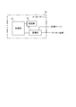
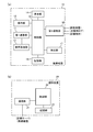
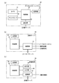
- FIG. 3A is a block diagram illustrating a configuration of the mobile device
- FIG. 3B is a block diagram illustrating a configuration of the reading device
- 4A is a block diagram showing the configuration of the digital mirror system
- FIG. 4B is a block diagram showing the configuration of the store server
- FIG. 4C shows the configuration of the store terminal.
- It is a block diagram. It is a figure which shows the state which the user is using the reading apparatus and a digital mirror system.
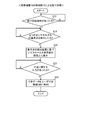
- It is a flowchart which shows the measuring process by the control part of a portable apparatus.
- FIG. 3A is a block diagram illustrating a configuration of the mobile device
- FIG. 3B is a block diagram illustrating a configuration of the reading device
- 4A is a block diagram showing the configuration of the digital mirror system
- FIG. 4B is a block diagram showing the configuration of the store server
- FIG. 4C shows the configuration of the store terminal.
- It is a block diagram. It is a figure which shows the state which the user
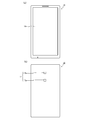
- FIG. 7A is a plan view of the mobile device
- FIG. 7B is a rear view of the mobile device.
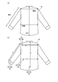
- Fig.8 (a) is a figure for demonstrating the dimension (measurement location) of clothing
- FIG.8 (b) is a figure which shows the reference
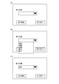
- FIG. 9A to FIG. 9C are diagrams showing the measuring screen.
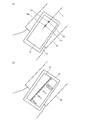
- FIG. 10A and FIG. 10B are diagrams for explaining measurement using a portable device.
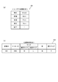
- Fig.11 (a) is a figure which shows the data structure of user dimension information DB
- FIG.11 (b) is a figure (the 1) which shows the data structure of fitting clothes DB. It is a flowchart which shows the clothing information reading process by the control part of a portable apparatus.
- FIG. 15A is a diagram showing the data structure of the recommended manufacturer size DB
- FIG. 15B is a diagram showing the data structure of the recommended item DB
- FIG. 16A is a flowchart showing processing by the control unit of the digital mirror system
- FIG. 16B is processing performed by the control unit of the portable device performed in parallel with the processing of FIG.
- FIG. 20A is a flowchart showing the sales process by the control unit of the store terminal
- FIG. 20B is a flowchart showing the database update process by the control unit of the store server
- 21A is a diagram showing the data structure of the inventory DB
- FIG. 21B is a diagram showing the data structure of the size selection DB
- FIG. 21C is the data of the simultaneous purchase product DB. It is a figure which shows a structure.
- FIG. 1 is a block diagram showing the configuration of the merchandise distribution support system 100.
- the merchandise distribution support system 100 is a system that supports a business in a manufacturer or a store by assisting a user in purchasing a product or managing / analyzing information on a product purchased by the user.
- the merchandise distribution support system 100 includes an in-store system 90 installed in each of a plurality of stores, a manufacturer server 50 installed in each of a plurality of manufacturers, and a manufacturer connected to each manufacturer server 50.
- the in-store system 90 and the manufacturer server 50 are connected to a network 110 such as the Internet.
- the in-store system 90 is a system that is provided in a store that sells merchandise (in the present embodiment, it is assumed to be clothes) and supports the purchase of merchandise by a user who owns the mobile device 10 or collects purchase information of the user. is there. Details of the in-store system 90 will be described later.
- the manufacturer server 50 is a server owned by each manufacturer who manufactures clothing and delivers it to the store.
- FIG. 2 is a block diagram showing the configuration of the manufacturer server 50.
- the manufacturer server 50 includes a communication unit 51, a storage unit 52, and a control unit 53, as shown in FIG.
- the communication unit 51 communicates with the store server 40 incorporated in the store system 90 via the network 110.
- the communication unit 51 communicates with the manufacturer terminal 75 via a LAN (Local Area Network) or the like.
- storage part 52 memorize
- the control unit 53 includes a CPU (Central Processing Unit), a RAM (Random Access Memory), a ROM (Read Only Memory), and the like, and controls the maker server 50 as a whole. In the present embodiment, the control unit 53 transmits information regarding the size of clothes recommended by the manufacturer stored in the storage unit 52 to the store server 40 via the communication unit 51.
- control part 53 receives the information regarding the sales situation of the clothes which a manufacturer manufactures from the store server 40 via the communication part 51, and analyzes the said information. And the control part 53 stores the information regarding the sales situation of the clothes which a manufacturer manufactures, and its analysis result in the memory
- the manufacturer terminal 75 is a PC (Personal Computer), a tablet terminal, or the like, and is a terminal for browsing information held in the storage unit 52 by the manufacturer server 50.
- PC Personal Computer
- the manufacturer terminal 75 is a PC (Personal Computer), a tablet terminal, or the like, and is a terminal for browsing information held in the storage unit 52 by the manufacturer server 50.
- the in-store system 90 includes a mobile device 10 held by a user, a reading device 20, a digital mirror system 30, a store server 40, and a store terminal 60. Since the mobile device 10 in FIG. 1 means a mobile device of a user who has entered the store, the type and number of mobile devices change according to the user's entrance and exit.
- the mobile device 10 is a terminal such as a mobile phone or a smartphone.
- the mobile device 10 has a call function, an e-mail creation / transmission function, an Internet connection function, a schedule management function, and the like.
- the mobile device 10 communicates with a function for measuring clothes worn by the user and a clothes tag 80 provided on clothes in the store, and the user wants to try on. It has a function of acquiring information on clothes (clothing ID, size, color, etc.).
- the mobile device 10 has a function of providing the reader 20 with measurement results and information on clothes that the user wants to try on, and information on the size suitable for the user's body (information on the recommended size of the manufacturer). It also has a function of receiving from 20.
- FIG. 3A shows the configuration of the mobile device 10 in a block diagram.
- the mobile device 10 includes a first communication unit 11, a second communication unit 12, a voice processing unit 13, a display unit 14, an operation unit 15, a storage unit 16, a detection unit 17, and a control unit. 18 etc.
- the first communication unit 11 has a radio communication circuit and an antenna, receives a signal transmitted from the base station via a radio channel, and performs frequency conversion processing by the radio communication circuit to obtain voice data.
- the second communication unit 12 performs, for example, proximity communication such as Bluetooth (registered trademark), Felica (registered trademark), RFID (Radio Frequency Identification), or human body communication via a user.
- the second communication unit 12 includes an RFID reader that performs proximity communication with a clothing tag 80 (assumed to be an RFID tag), and Felica (registered) that performs proximity communication with the reading device 20. Trademark) chip.
- the sound processing unit 13 has a circuit for performing D / A conversion and amplification, and outputs sound from a speaker (not shown).
- the user's utterance is collected by a microphone (not shown), converted into a transmission signal, and transmitted to the voice processing unit 13.
- the audio processing unit 13 performs amplification and A / D conversion of the transmission signal to generate digital data, and transmits this digital data to the base station via the first communication unit 11.
- the display unit 14 is, for example, a liquid crystal display, and displays, for example, various information such as date and time information, Web information (Web page), schedule data, and a screen for instructing the start of processing by the mobile device 10. To do.
- the operation unit 15 includes a touch panel and a virtual keyboard.
- the storage unit 16 includes, for example, a non-volatile flash memory, and in addition to various programs, information related to the size of the clothes worn by the user (that is, the size of the user's body) (user size information DB 201 (FIG. 11 (a ))), And information on clothes that the user wants to try on at the store (fitting clothes DB 203 (see FIG. 11B)) and the like.
- the dimensions of the clothes worn by the user and the dimensions and image data of the clothes possessed by the user are acquired from the clothes tag 80, the store server 40, and the manufacturer server 50, which will be described later, at the time of purchase. Can be stored.
- the detection unit 17 detects a reference point 70 (see FIG. 8B) provided on the clothes 95 worn by the user.
- a sensor that electrically detects a reference point 70 formed of a conductive thread, metal, or the like can be used. Details of the detection unit 17 and the reference point 70 will be described later.
- the control unit 18 includes a CPU, a RAM, a ROM, and the like, and controls the entire portable device 10.
- the control unit 18 causes the detection unit 17 to detect the reference point 70, causes the display unit 14 to display a screen for measuring, or other devices via the second communication unit 12. It controls the exchange of information with (reading device 20, clothing tag 80, store terminal 60).
- the reading device 20 is provided in a store so that the portable device 10 can be placed on the upper surface thereof.
- the reading device 20 includes a communication unit 21, a storage unit 23, and a control unit 24.
- the reading device 20 may be provided in the digital mirror system 30 (may be part of the configuration of the digital mirror system).
- the communication unit 21 communicates with the mobile device 10 by proximity communication.
- the communication unit 21 includes a reader / writer that performs communication with the Felica (registered trademark) chip included in the second communication unit 12 of the mobile device 10.
- the communication unit 21 communicates with the store server 40 by wired or wireless communication.
- the control unit 24 comprehensively controls each unit of the reading device 20.
- the control unit 24 acquires various information (such as dimensional information of a user who owns the mobile device 10 and information on a product to be tried on) from the mobile device 10 via the communication unit 21.
- the storage unit 23 temporarily stores information that the control unit 24 exchanges between the mobile device 10 and the store server 40.
- the digital mirror system 30 is a system that is installed in a store and implements virtual try-on (virtual try-on) of clothes by a user.
- the digital mirror system 30 includes a camera 31, a display 32, a communication unit 33, a storage unit 34, and a control unit 35.
- the camera 31 is a camera that can capture the state in front of the display 32 with a moving image.
- the display 32 displays the image captured by the camera 31 with a mirror image inverted.
- the user in front of the mirror can confirm his / her appearance on the display 32 with the same feeling as if he / she was reflected in a general mirror (view).
- the control unit 35 may perform a process of masking an image located behind the position where the user who tries on stands by using a distance sensor.
- a focus detection device may be provided in the camera 31 to perform distance measurement in a range captured by the camera 31, and a distance image (depth distribution image) may be generated to determine a masking region.
- the imaging region can be selected two-dimensionally (row direction and column direction).
- a stacked imaging element is formed by stacking an imaging chip (for example, a backside-illuminated imaging chip), a signal processing chip, and a memory chip and electrically connected by conductive bumps.
- the display 32 displays an image of clothes that the user wants to try on on the user's image and displays recommended items corresponding to the clothes that the user wants to try on.
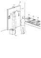
- FIG. 5 shows a state in which a long-sleeved shirt is synthesized and displayed on an image of a user wearing a short-sleeved shirt.
- the display 32 may display the amount of clothes or accessories to be tried on in the vicinity of the displayed image.
- the first communication unit 11 or the second communication unit 12 may be used to display the amount on the display unit 14 of the mobile device 10, which is worn by the user. You may make it display on the display part of a wearable terminal (timepiece, glass).
- the communication unit 33 communicates with the store server 40 by wire or wireless.
- the storage unit 34 stores clothes, recommended items, and image data of the mobile device 10.
- the control unit 35 includes a CPU and the like, and comprehensively controls the entire digital mirror system 30. In the present embodiment, the control unit 35 controls the display on the display 32 as described above, as well as a human action (for example, an operation of touching a recommended item (operation to select), or a recommended item on an image of a portable device). When such detection is performed, a predetermined process (details will be described later) is executed.
- the store server 40 manages information used in the in-store system 90 and provides necessary information to the reading device 20 and the digital mirror system 30. Further, purchase information of a product by a user is acquired from the store terminal 60, managed and analyzed, and provided to the store terminal 60 and the manufacturer server 50.
- the store server 40 includes a communication unit 41, a storage unit 43, and a control unit 44, as shown in FIG.
- the communication unit 41 communicates with the reading device 20, the store terminal 60, and the digital mirror system 30 by wire or wireless.
- the communication unit 41 communicates with the manufacturer server 50 via the network 110.
- the storage unit 43 includes a manufacturer recommended size DB 211 (see FIG. 15A), a recommended item DB 213 (see FIG. 15B), an inventory DB 215 (see FIG. 21A), and a size selection DB 217 (FIG. 21B). (Refer to FIG. 21 (c)).
- the control unit 44 includes a CPU and the like, and comprehensively controls the store server 40 as a whole. Further, the control unit 44 acquires various information from the reading device 20, the store terminal 60, and the manufacturer server 50.
- the store terminal 60 is connected to the store server 40.
- the store terminal 60 has a function of receiving information on a product to be purchased by the user from the mobile device 10, and a product purchased by the user.
- the function of transmitting the information to the store server 40 is provided.
- the store terminal 60 includes a communication unit 61, a storage unit 62, a control unit 63, a display unit 64, and an input unit 65.
- the communication unit 61 communicates with the mobile device 10 by proximity communication.
- the communication unit 61 includes a reader / writer that performs communication with the Felica (registered trademark) chip included in the second communication unit 12 of the mobile device 10.
- the communication unit 61 communicates with the store server 40 by wired or wireless communication.
- the storage unit 62 stores price data for each product.
- the storage unit 62 stores information on products purchased by the user.
- the control unit 63 controls the store terminal 60 as a whole.
- the display unit 64 displays information such as information on a product that the user intends to purchase and a price.
- the input unit 65 includes a keyboard, a mouse, and the like, and is used by a user (store clerk) of the store terminal 60 to input various information.
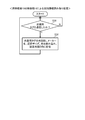
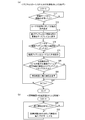
- FIG. 6 shows a flowchart of the measuring process executed by the control unit 18 of the mobile device 10.
- FIG. 7A shows a plan view of the mobile device 10 and
- FIG. 7B shows a rear view of the mobile device 10.
- FIG. 8A shows the objects to be measured of the garment 95 (sleeve length, shoulder width, width of a garment, and length), and
- FIG. 8B shows reference points provided at various points on the garment 95. 70 is shown.
- the reference point 70 includes a main reference point 70a and a sub reference point 70b.
- the sensors 17a and 17b of the detection unit 17 provided on the back surface (a surface different from the surface on which the display unit 14 is provided) of the mobile device 10 are located at which position of the sensors 17a and 17b, the main reference point 70a, This is a sensor that can determine whether the sub-reference point 70b has been detected. Therefore, the control unit 18 can detect the inclination of a straight line connecting the main reference point 70a and the sub reference point 70b. Note that the positional relationship between the main reference point 70a and the sub reference point 70b may be different from that in FIG.
- the sensors 17a and 17b a sensor in which a plurality of electrodes that can contact the reference point 70 are arranged in a two-dimensional direction, a camera (image sensor), or the like can be used.
- a camera image sensor
- the control unit 18 of the portable device 10 waits until a measurement start instruction is input from the user in step S10 of FIG.
- the measurement screen as shown in FIG. 9A is displayed on the display unit 14 of the mobile device 10 via the operation unit 15 (touch panel or the like).
- the downward triangular button on the right side of the measurement target input field is pressed, and the measurement target options as shown in FIG. 9B are displayed.
- the user can issue a measurement start instruction to the control unit 18 by selecting one measurement target from the options as shown in FIG. 9C and pressing a measurement start button.
- the control unit 18 proceeds to step S16.
- step S16 the control unit 18 waits until each of the two sensors 17a and 17b included in the detection unit 17 of the mobile device 10 detects the reference point 70 (70a and 70b).
- the user positions the portable device 10 in the vicinity of the reference point of the measurement target (sleeve length) as shown in FIG. 10 (a), and uses the sensors 17a and 17b as a reference.
- the mobile device 10 is moved so that the point 70 (70a, 70b) is detected.
- the control unit 18 proceeds to step S20.
- the control part 18 may alert
- step S20 the control unit 18 displays the scale on the screen of the display unit 14 based on the detection result of the reference point 70 (see FIG. 10B).
- the user can know that the sleeve length is 62.2 cm by looking at the scale and the end of the sleeve of the clothes 95 in the state of FIG.
- the user inputs a sleeve length measurement result to the control unit 18 by touching a 62.2 cm portion of the operation unit 15 (touch panel).
- the present invention is not limited to this, and the user may manually input the measurement result of the sleeve length on a predetermined input screen.
- 0 cm may be displayed at the position where the main reference point exists on the display unit 14.
- step S ⁇ b> 22 the control unit 18 stands by until there is an input regarding the dimension from the user. And if there exists an input from a user, it will transfer to step S24 and the control part 18 will store dimension data in user dimension information DB201 (FIG.11 (b)). Thus, the measuring process in FIG. 6 ends.
- the user can measure other dimensions (shoulder width, width, length, etc.) by the same method as described above.
- the scale may be displayed on the display unit 14 by detecting the reference point 70 provided near the shoulder by the detection unit 17.
- the scale may be displayed on the display unit 14 by detecting the reference point 70 provided near the flank by the detection unit 17.
- the scale may be displayed on the display unit 14 by detecting the reference point 70 provided near the waist by the detection unit 17.
- the outer garment (shirt) is taken as an example, but the same measurement is possible for trousers.
- the scale may be displayed on the display unit 14 by detecting the reference point provided near the hem of the pants by the detection unit 17. Thereby, the user can input the positional information on the skirt position of the pants using the scale.
- the old value is updated with the new measurement result value. This is because the size of the user's body changes from day to day. In addition, you may make it add a user's height and weight as dimension information or user information.
- step S30 the control unit 18 of the portable device 10 stands by until communication between the clothing tag 80 and the second communication unit 12 is established. That is, when the portable device 10 and the clothing tag 80 are close to being communicable, the determination in step S30 is affirmed, and the control unit 18 proceeds to step S32.
- step S32 the control unit 18 reads the clothing ID, manufacturer name, selected size, and color information of the clothing from the clothing tag 80 via the second communication unit 12, and tries on as shown in FIG. Stored in the clothing ID, manufacturer name, selected size, and color fields of the clothing DB 203.
- steps S30 and S32 are repeatedly executed. Thereby, whenever the user performs an operation of bringing the mobile device 10 close to the clothing tag 80, the clothing information is stored in the fitting clothing DB 203.
- the user places on the reading device 20 the portable device 10 in which the user's dimensional information and information on clothes to be tried on are already stored.
- the processes of the control unit 24 of the reading device 20, the control unit 44 of the store server 40, the control unit 35 of the digital mirror system 30, and the control unit 18 of the portable device 10 in this case will be described with reference to FIGS. 13, 14, and 16. This will be described in detail along the flowchart.
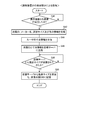
- FIG. 13 is a flowchart showing processing by the control unit 24 of the reading device 20.
- the control unit 24 waits until communication with the mobile device 10 is established. In this case, when the user places the mobile device 10 on the reading device 20 and communication between the second communication unit 12 and the communication unit 21 is established, the control unit 24 proceeds to step S42.
- step S42 the control unit 24 receives information on the clothes ID, the manufacturer name, the selected size, and the color from the portable device 10 via the communication unit 21.
- step S ⁇ b> 44 the control unit 24 receives user dimension information from the portable device 10 via the communication unit 21. Note that the order of steps S42 and S44 may be reversed.
- step S46 the control unit 24 transmits the clothing ID and the dimension information of the user among the information received in steps S42 and S44 to the store server 40 via the communication unit 21.
- step S48 the process waits until the recommended size is transmitted from the store server 40.
- the recommended size is determined by the processing of FIG. 14, and information of the recommended size is transmitted to the reading device 20 (details will be described later).
- the control unit 24 proceeds to step S ⁇ b> 50, receives the recommended size information from the store server 40 via the communication unit 21, and stores it in the fitting clothes DB 203.
- control unit 44 executes processing according to the flowchart of FIG.
- step S ⁇ b> 60 the control unit 44 waits until the clothing ID and the user dimension information are received from the reading device 20 via the communication unit 41. In this case, the control unit 44 proceeds to step S62 when the control unit 24 of the reading device 20 performs the process of step S46 of FIG. 13 described above.
- the control unit 44 refers to the manufacturer recommended size DB 211, determines the recommended size of the user, and transmits it to the reading device 20 via the communication unit 41.
- the manufacturer recommended size DB 211 has a data structure as shown in FIG. 15A as an example.
- the data of the manufacturer recommended size DB 211 stores data of recommended sizes of products manufactured by each manufacturer transmitted from each manufacturer server 50.
- step S64 the control unit 44 extracts a recommended item ID corresponding to the clothes ID from the recommended item DB 213.
- the control unit 44 extracts (103, 205) from the recommended item DB 213 as the recommended item ID.
- step S66 the control unit 44 transmits the clothing (clothing ID), manufacturer name, recommended size, color, and recommended item ID selected by the user to the digital mirror system 30 via the communication unit 41. To do.
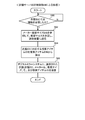
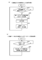
- FIG. 16A shows a process of the control unit 35 in a flowchart. As a premise of the processing in FIG. 16A, it is assumed that the control unit 35 displays the image captured by the camera 31 on the display 32 by inverting the mirror image.
- control unit 35 waits until information is received from the store server 40 via the communication unit 33 in step S70. In this case, at the stage where the control unit 44 of the store server 40 has performed the process of step S66 of FIG. 14 described above, the control unit 35 proceeds to step S72.
- the control part 35 will display the image of the clothes corresponding to clothes ID, manufacturer name, recommended size, and color which were received at step S70 with respect to the image of the person (user) displayed on the display 32. Is displayed. Thereby, as shown in FIG. 5, the user wearing the short-sleeved shirt can virtually try on the long-sleeved shirt. Moreover, since the user actually wears the trousers, the user can check the combination of the trousers and the short-sleeved shirt worn. Instead of this, the image data of the pants stored in the storage unit 16 and possessed by the user may be displayed on the display 32.
- control unit 35 may display the recommended size to the user by displaying the size of the clothes that the user is trying on on the display 32.
- the clothing image is stored in the storage unit 34, but the control unit 35 may download the image from the manufacturer server 50 and display it as needed.
- control unit 35 uses the voice processing unit 13 of the mobile device 10 or the voice recognition unit (not illustrated) of the digital mirror system 30 to receive a voice from the user (for example, the size is increased, the size is increased, the size is increased). Small, long sleeves, short sleeves, etc.) and the recommended size may be changed or adjusted according to the recognized voice. In this case, the control unit 35 may correspond to a custom order.
- step S74 the control unit 35 displays the recommended item and the image of the portable device on the display 32.
- FIG. 5 as an example, an image of an item corresponding to the recommended item ID (in FIG. 5, an image of a hat and a tie) is displayed on the right side of the user, and an image of a portable device is displayed on the left side.
- the image of the recommended item and the image of the portable device are stored in the storage unit 34, but the control unit 35 downloads the image from the maker server 50 and displays it as needed. It is good.
- step S76 it is determined whether or not the user has performed an action (gesture) touching the recommended item.
- the control unit 35 may determine whether or not the user has performed an action of touching the item based on the user's movement (gesture) extracted from the image captured by the camera 31. That is, in the case of FIG. 17, when a user standing at a predetermined position raises his right hand to a predetermined height, it is determined that the user has touched the hat, and when the right hand is raised to a height lower than the predetermined height, It can be determined that it has been touched. If the determination in step S76 is affirmative, the control unit 35 proceeds to step S78.
- the control part 35 will synthesize
- step S80 If the determination in step S76 is negative, the control unit 35 proceeds to step S80 without passing through step S78.
- step S80 the control unit 35 determines whether or not the operation of dragging and dropping the synthetically displayed clothes or the recommended item onto the image of the mobile device has been performed. When judgment here is affirmed, it transfers to step S82.
- the drag-and-drop operation means an operation in which the user moves the hand over the image of the portable device after performing the operation of grasping the image displayed in a composite manner.
- step S ⁇ b> 82 the control unit 35 transmits to the mobile device 10 purchase information on clothes or recommended items that are intended to be purchased. For example, as shown by an arrow B in FIGS. 17 and 18, when the user performs an operation of dragging and dropping an image of a hat, a tie, or a shirt on an image of a portable device, the control unit 35 A hat, tie, or shirt ID (clothing ID) and purchase information are transmitted to the mobile device 10. The control unit 35 transmits the purchase information to the mobile device 10 via the store server 40 (control unit 44, communication unit 41) and the reading device 20 (control unit 24, communication unit 21). do it. Thereafter, the control unit 35 proceeds to step S84. In addition, also when the judgment of step S80 is denied, it transfers to step S84.
- step S84 the control unit 35 determines whether or not the process is finished. For example, when the user is out of the field of view of the camera 31 (when the user no longer appears on the display), the control unit 35 determines that the process is finished. If the determination here is negative, the process returns to step S76, but if the determination is positive, the entire process of FIG.
- the clothing after the second focus may be displayed in a synthesized manner on the user's image.
- the clothes after the 2nd attention can be compatible with the clothes of the 1st attention (when the clothes can be layered or combined with a shirt and trousers, etc.)
- the clothes of the 1st attention and the clothes after the 2nd attention are synthesized simultaneously. What is necessary is just to display.
- control unit 18 of the portable device 10 (Processing of the control unit 18 of the portable device 10) It is assumed that the control unit 18 of the mobile device 10 is executing the process of FIG. 16B concurrently with the process of FIG. In the process of FIG. 16B, the control unit 18 waits until purchase information is received via the second communication unit 12 in step S90. In this case, the control unit 35 proceeds to step S92 when the process of step S82 in FIG.
- step S92 the control unit 18 sets the purchase flag of the fitting clothes DB 203 to 1.
- Such a user may operate the mobile device 10 to display the fitting clothes DB 203 (FIG. 11B) on the display unit 14 and change the purchase flag from 0 to 1. That is, the user may input purchase information into the mobile device 10 by manual input.
- FIG. 20A illustrates a flow of processing executed by the control unit 63 of the store terminal 60 in a flowchart.
- step S102 the control unit 63 waits until communication with the portable device 10 is established.
- the control unit 63 proceeds to step S104. Transition.
- step S106 the control unit 63 executes accounting processing.
- the store clerk confirms the display of the sales instruction
- the store clerk may sell the product stored in the warehouse (backyard) to the user. In this case, since the product tried on by the user is not sold as it is, it is possible to reduce the trouble of packing the product.
- the control unit 63 calculates a change or the like.
- step S108 the control unit 63 transmits the sales data to the store server 40. Specifically, the control unit 63 transmits the data acquired in step S104 to the store server 40. Thereafter, the process returns to step S102, and the same processing as described above is repeated.
- step S120 the control unit 44 waits until sales data is received from the store terminal 60. In this case, the process proceeds to step S122 when the process of step S108 in FIG. In step S122, the control unit 44 updates the stock DB 215, the size selection DB 217, and the simultaneous purchase product DB 219.
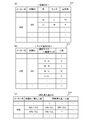
- the stock DB 215 is a database for managing the number of stocks for each clothing color and size, as shown in FIG. Each time clothing of a certain color and size is sold, the control unit 44 updates the inventory DB 215 so as to reduce the stock quantity of the clothing of that color and size.
- the size selection DB 217 is a database for managing the number of purchased users for each product and for each relationship between the selected size and the recommended size, as shown in FIG.
- the control unit 44 updates the size selection DB 217 so that the number of purchases corresponding to the selected size and recommended size of the purchased user is increased every time clothing is sold.
- the simultaneous purchase product DB 219 is a database that stores the number of users who have purchased another product at the same time among users who have purchased a certain garment. Each time clothing is sold, the control unit 44 increases the number of people in the column corresponding to the ID of the clothing and updates the simultaneous purchase product DB 219 so as to increase the number of people in the column corresponding to the simultaneous purchase product ID.
- each DB215,217,219 can be referred suitably.
- the store clerk can perform inventory management, order placement from the manufacturer, and the like based on the inventory DB 215. Further, the store clerk can know the size tendency (larger, smaller, thicker, thinner, etc.) for each manufacturer based on the size selection DB 217. For example, in FIG. 21B, since the L size is recommended for many people who usually wear the M size, it can be known that the L size is made smaller. Thereby, the store clerk can inform the customer of the tendency of the size for each manufacturer at the time of customer service. Note that the size trend varies from manufacturer to manufacturer because the design concept, target customer base, etc. vary from manufacturer to manufacturer.
- the store clerk can know the products that the customers tend to purchase at the same time based on the simultaneous purchase product DB 219, the store clerk can notify the recommended items even to customers who do not try virtual fitting. In order to improve sales, the store clerk can also display products that are purchased at the same time, or have the mannequin wear (display) the products that are purchased at the same time. Note that the control unit 44 of the store server 40 may appropriately update the recommended item DB 213 in FIG. 15B based on the simultaneous purchase product DB 219.
- the store server 40 or the store terminal 60 analyzes the data of each DB 215, 217, 219 from the viewpoint described above, and the analysis result is displayed on the display unit of the store terminal 60. 64 may be displayed.
- Each store server 40 transmits data corresponding to the manufacturer (data of products manufactured by the manufacturer) among the data in the DBs 215, 217, and 219 to the manufacturer server 50.
- data may be transmitted from each store server 40 to the manufacturer server 50 at predetermined time intervals (for example, once a day).
- the maker server 50 can collect the information regarding the company product accumulated at each store.
- a user (such as a marketing department, a product development department, or a product planning department) who uses the maker terminal 75 can access the maker server 50 to view information on the collected company products.
- the manufacturer can know the information on the stock quantity of each store, it can prepare delivery to each store based on the information.
- the manufacturer can know the trend of sales from the change in the number of stocks every day. Based on that information, whether to continue selling products, whether to increase the number of production, etc. Judgment can be made.
- the manufacturer can know the trend of the size of its product, it is possible to take measures to make the information known to customers and store clerk.
- the manufacturer can know information on the products purchased at the same time, it is possible to determine the direction of product development and to develop a sales strategy based on the information.
- the manufacturer server 50 or the manufacturer terminal 75 analyzes the data collected from the store server 40 from the viewpoint as described above, and displays the analysis result on the manufacturer terminal 50. It may be displayed on the part.
- the mobile device 10 detects the reference point 70 provided on the clothing 95 and the display unit 14 based on the detection result of the reference point 70. And a control unit 18 for displaying a scale on the screen.
- the user can perform measurement without moving the portable device 10 along the measurement location. It can be carried out.
- the control unit 18 determines the inclination of the scale based on the detection results of these reference points 70a and 70b. Since it is determined and displayed, accurate measurement in consideration of the angle between the mobile device 10 and the clothes 95 is possible.
- the user can input the measurement result to the control unit 18 by a simple operation of touching the scale.
- the user has described the case where the size of the worn clothes is measured using the mobile terminal 10, but the present invention is not limited to this.
- the user may measure the size of clothes to be purchased using the mobile terminal 10.
- the reference point 70 has been described as having two reference points (70a, 70b).
- the present invention is not limited to this, and the reference point 70 has one or more reference points. Also good.
- the detection unit 17 has been described as having two sensors 17a and 17b.
- the detection unit 17 is not limited to this, and the detection unit 17 may include one or more sensors having a predetermined detection area. You may have.
- the reference point 70 is a conductive thread or metal.
- the control unit 18 of the mobile device 10 displays a straight line in the short direction of the display unit 14 and displays a scale so as to be orthogonal to the straight line, so that the user can detect the straight line and the skirt in the short direction. By aligning, the length from the hem can be measured.
- the control unit 18 may display two marks separated in the short direction instead of the straight line in the short direction.
- the control part 18 of the portable apparatus 10 is good also considering a scale display as mm display.
- the control unit 18 may switch the unit of the scale such as inch display if the user is in the United States, for example, according to the output of a GPS module (position detection device) (not shown) of the mobile device 10.
- the control unit 44 of the store server 40 acquires the length measurement result (measurement result of the user's body) stored in the mobile device 10, and the user receives the mobile device 10.
- the information of the product related to the length measurement object specified using (the product related to the body, clothing in this embodiment) is acquired.
- the control part 44 presents the goods (clothes of the size suitable for a user's body) recommended with respect to a user based on the acquired information.
- the user can know the recommended product based on the length measurement result that is the product specified by the user. That is, according to the store server 40 of the present embodiment, it is possible to present to the user recommended products in consideration of the user's wishes.
- users can know recommended products (recommended sizes) without having to communicate with the store clerk in the store, so users who are not good at communication, users who are troubled with conversations with the store clerk, and product purchases Usability for a user who is in a hurry can be improved.
- control unit 44 presents a product (recommended item) that can be used together with the recommended product together with the recommended product to the user. Thereby, the user can know the goods (accessory and accessory) which can be used with the recommended goods which considered the user's hope.
- the digital mirror system 30 includes the camera 31 that images the user and the display 32 that displays a mirror image of the image captured by the camera 31.
- the product (recommended size clothing or recommended item) presented by the unit 44 is displayed superimposed on the user's image. Accordingly, the user can virtually try on clothes or recommended items of recommended sizes (virtual try-on).
- a plurality of cameras 31 for example, two may be used, and a plurality of users may be tried on virtually at the same time. In this case, it is possible to efficiently coordinate with a pair such as a parent and child, a lover, a couple, and a brother.
- a plurality of portable terminals 10 may be placed on the reading device 20, and the dimension information of the user and the image data of clothes to be tried on may be read from the respective portable terminals 10 by the reading device 20.
- the camera 31 can be adjusted in the vertical and horizontal positions by an adjustment mechanism (not shown), it is possible to perform appropriate imaging according to the height and position of the user.
- control unit 35 transmits product information to the mobile device 10 in accordance with the user's selection operation (drag and drop operation) on the product displayed superimposed on the user's image.
- the user can store information (for example, purchase information) of the product virtually tried on the mobile device 10 with a simple operation.
- control unit 44 relates to the product based on at least one of the information acquired from the mobile device 10, the information of the recommended product (recommended size of clothes), and the information of the product purchased by the user. Perform analysis. Thereby, the store clerk and the maker employee can determine a product provision method and a product development policy from various viewpoints.
- the display of the recommended size for the user or the recommended item for the user may be performed using the display unit 14 of the mobile device 10. Or it is good also as printing out the information of the goods of recommended size and the information of recommended items using the printer installed in the shop, and showing it to a user.
- the portable device 10 may be provided with a measuring unit capable of measuring the movement amount of the portable device 10 in the same manner as an optical mouse or a trackball type mouse, and the measuring unit may execute the measurement.
- the wheel-shaped member for measuring may be provided in the portable apparatus 10, and you may make it measure based on the rotation amount of the said wheel-shaped member.
- the mobile device 10 does not have a measuring unit, the user may manually input his / her size.
- the said embodiment demonstrated the case where goods were clothes, it is not restricted to this.
- the electrical appliances currently used such as washing machines and New appliances (such as washing machines and TVs) of the appropriate size based on the measurement results of the TVs etc. and the type and manufacturer information of the appliances (such as washing machines and TVs) that you want to purchase.
- the reference point 70 may be provided at a predetermined position of the appliance.
- the mobile device 10 acquires information such as the clothing ID by performing close proximity communication with the clothing tag 80 .
- You may make it acquire information, such as clothes ID, by image
- the user may manually input information such as clothes ID to the mobile device 10.
- a recommended product (clothing of recommended size) was shown to a user in a store
- a server that can communicate with the home PC has a size recommended by the manufacturer based on the size information and the desired product information. It is good also as providing this information to a user.
- clothes of recommended sizes are displayed on the user's image captured using the camera, or images of recommended items are displayed in combination. You may make it do.
- the digital mirror system 30 may be sold or rented and provided in each facility such as a home, school (for uniform measurement), a hospital, an elderly care facility, and the like.
- data on clothes to be tried on may be acquired in advance from the clothes tag 80 using the mobile device 10 or may be acquired from the store server 40 or the manufacturer server 50 via the Internet or the like.
Landscapes
- Health & Medical Sciences (AREA)
- Life Sciences & Earth Sciences (AREA)
- Engineering & Computer Science (AREA)
- Physics & Mathematics (AREA)
- Medical Informatics (AREA)
- Pathology (AREA)
- Biomedical Technology (AREA)
- Heart & Thoracic Surgery (AREA)
- Biophysics (AREA)
- Molecular Biology (AREA)
- Surgery (AREA)
- Animal Behavior & Ethology (AREA)
- General Health & Medical Sciences (AREA)
- Public Health (AREA)
- Veterinary Medicine (AREA)
- Business, Economics & Management (AREA)
- Oral & Maxillofacial Surgery (AREA)
- Dentistry (AREA)
- Finance (AREA)
- Accounting & Taxation (AREA)
- Signal Processing (AREA)
- Nuclear Medicine, Radiotherapy & Molecular Imaging (AREA)
- Multimedia (AREA)
- Radiology & Medical Imaging (AREA)
- Development Economics (AREA)
- Economics (AREA)
- Marketing (AREA)
- Strategic Management (AREA)
- General Business, Economics & Management (AREA)
- General Physics & Mathematics (AREA)
- Theoretical Computer Science (AREA)
- Management, Administration, Business Operations System, And Electronic Commerce (AREA)
Abstract
携帯端末(10)からデータを取得する取得部(20)と、ユーザを撮像する撮像部(31)と、前記データに関連する情報と、前記撮像部が撮像した前記ユーザの画像とを表示する表示部(32)と、を備えた使い勝手のよい電子機器を提供する。
Description
本発明は、電子機器に関する。
従来、顧客を撮像した画像から被写体の寸法を推測し、該寸法に基づいて顧客に適合する衣服等のサイズ分類を提供する装置が知られている(例えば、特許文献1参照)。
しかしながら、従来は、顧客のデータ(寸法など)を利用した、使い勝手のよい電子機器に関する提案が十分ではなかった。
本発明は上記の課題に鑑みてなされたものであり、使い勝手のよい電子機器を提供することを目的とする。
本発明の電子機器は、携帯端末からデータを取得する取得部と、ユーザを撮像する撮像部と、前記データに関連する情報と、前記撮像部が撮像した前記ユーザの画像とを表示する表示部と、を備えている。
この場合において、前記取得部は、前記ユーザのサイズの情報を取得することとしてもよい。また、前記取得部は、前記携帯端末が近接通信により取得した前記データを取得することとしてもよい。また、前記表示部は、前記データに関連する情報として、身に着ける物品の画像を表示することとしてもよい。この場合、前記表示部は、前記身に着ける物品の画像を前記ユーザの画像に重ね合わせて表示することとしてもよい。
本発明の電子機器において、前記取得部は、前記ユーザが選択した身に着ける物品の情報を取得することとしてもよい。また、電子機器は、前記データに関連する情報に対する前記ユーザの選択動作に応じて、前記データに関連する情報を前記携帯端末に送信する送信部、を備えていてもよい。また、前記取得部は、前記携帯端末を用いて計測したデータを取得することとしてもよい。また、前記取得部は、前記ユーザが所持している衣服のデータを取得することとしてもよい。
本発明の電子機器において、前記撮像部は、ユーザの手の動きを撮像し、前記表示部は、前記ユーザの手の動きに応じて表示を変更することとしてもよい。また、前記撮像部は、複数のユーザを撮像し、前記表示部は、前記複数のユーザの画像を表示することとしてもよい。また、本発明の電子機器は、前記撮像部が撮像した画像データの一部の前記表示部への表示を制限する制限部を備えていてもよい。また、前記撮像部は、積層型の撮像素子を備え、電子機器は、前記ユーザを撮像する撮像領域の撮像条件と、前記ユーザがいない撮像領域の撮像条件とを異ならせる制御部を備えていてもよい。
本発明は、使い勝手のよい電子機器を提供することができるという効果を奏する。
以下、一実施形態に係る商品流通支援システム100について、図1~図21に基づいて、詳細に説明する。図1には、商品流通支援システム100の構成がブロック図にて示されている。商品流通支援システム100は、ユーザによる商品購入を支援したり、ユーザによって購入された商品の情報を管理・分析することで、メーカーや店舗における業務を支援するシステムである。
商品流通支援システム100は、図1に示すように、複数の店舗それぞれに設置された店舗内システム90と、複数のメーカーそれぞれに設置されたメーカーサーバ50と、各メーカーサーバ50に接続されたメーカー端末75と、を備える。店舗内システム90及びメーカーサーバ50は、インターネットなどのネットワーク110に接続されている。
店舗内システム90は、商品(本実施形態では、衣服とする)を販売する店舗内に設けられ、携帯機器10を保有するユーザによる商品購入を支援したり、ユーザの購入情報を収集するシステムである。店舗内システム90の詳細については、後述する。
メーカーサーバ50は、衣服を製造し店舗に納入するメーカーそれぞれが保有するサーバである。図2には、メーカーサーバ50の構成がブロック図にて示されている。
メーカーサーバ50は、図2に示すように、通信部51と、記憶部52と、制御部53と、を備える。通信部51は、ネットワーク110を介して、店舗システム90に組み込まれた店舗サーバ40と通信する。また、通信部51は、LAN(Local Area Network)等を介して、メーカー端末75と通信する。記憶部52は、メーカーが製造した衣服に関する各種情報を記憶する。制御部53は、CPU(Central Processing Unit)、RAM(Random Access Memory)、ROM(Read Only Memory)等を備え、メーカーサーバ50全体を制御する。本実施形態においては、制御部53は、通信部51を介して、店舗サーバ40に対して、記憶部52に記憶されているメーカーが推奨する衣服のサイズに関する情報を送信する。また、制御部53は、通信部51を介して、店舗サーバ40から、メーカーが製造する衣服の販売状況に関する情報を受信し、当該情報を分析する。そして、制御部53は、メーカーが製造する衣服の販売状況に関する情報及びその分析結果を記憶部52に格納したり、メーカー端末75からの求めに応じてメーカー端末75に提供したりする。
メーカー端末75は、PC(Personal Computer)やタブレット型端末などであり、メーカーサーバ50が記憶部52において保持している情報を閲覧等するための端末である。
次に、店舗内システム90の具体的構成について、図1、図3~図5に基づいて、詳細に説明する。
店舗内システム90は、図1に示すように、ユーザが保有する携帯機器10と、読取装置20と、デジタルミラーシステム30と、店舗サーバ40と、店舗端末60と、を備える。なお、図1の携帯機器10は、店舗に入店しているユーザの携帯機器を意味するため、ユーザの入退店に応じて携帯機器の種別や個数は変化するものとする。
携帯機器10は、携帯電話やスマートフォンなどの端末である。携帯機器10は、通話機能や、電子メールの作成・送受信機能やインターネット接続機能、スケジュール管理機能などを有する。また、本実施形態では、携帯機器10は、ユーザが着用している衣服を採寸するための機能や、店舗内の衣服に設けられた衣服用タグ80と通信し、ユーザが試着したいと考えている衣服の情報(衣服ID、サイズ、色など)を取得する機能を有する。また、携帯機器10は、採寸結果やユーザが試着したいと考えている衣服の情報を読取装置20に提供する機能や、ユーザの体に合ったサイズの情報(メーカー推奨サイズの情報)を読取装置20から受信する機能も有している。
図3(a)には、携帯機器10の構成がブロック図にて示されている。図3(a)に示すように、携帯機器10は、第1通信部11、第2通信部12、音声処理部13、表示部14、操作部15、記憶部16、検出部17、制御部18等を備える。
第1通信部11は、無線通信回路やアンテナを有し、基地局からの無線チャネルを介して送信される信号をアンテナにより受信し、無線通信回路により周波数変換の処理を行い音声データとする。
第2通信部12は、例えばBluetooth(登録商標)、Felica(登録商標)、RFID(Radio Frequency Identification)などの近接通信や、ユーザを介した人体通信などを行うものである。本実施形態では、第2通信部12は、衣服用タグ80(RFIDタグであるとする)と近接通信を行うRFIDリーダを有するとともにとともに、読取装置20との間で近接通信を行うFelica(登録商標)チップを有するものとする。
音声処理部13は、D/A変換や増幅を行うための回路を有し、不図示のスピーカから音声を出力する。また、ユーザの発話は、不図示のマイクロホンにより集音され、送信信号に変換されて音声処理部13に送信される。音声処理部13は送信信号の増幅やA/D変換を行ってデジタルデータとし、このデジタルデータを第1通信部11を介して基地局に送信する。
表示部14は、例えば液晶ディスプレイであり、例えば、日時の情報、Webの情報(Webページ)、スケジュールデータなどの各種情報のほか、携帯機器10による処理の開始を指示するための画面などを表示する。操作部15は、タッチパネルや仮想キーボードを含む。
記憶部16は、例えば不揮発性のフラッシュメモリを有し、各種プログラムのほか、ユーザが着用している衣服の寸法(すなわち、ユーザの体の寸法)に関する情報(ユーザ寸法情報DB201(図11(a)参照))や、ユーザが店舗にて試着したい衣服に関する情報(試着衣服DB203(図11(b)参照))などを記憶している。ユーザが着用している衣服の寸法や、ユーザが所持している衣服の寸法や画像データは、購入時に後述の衣服用タグ80や、店舗サーバ40や、メーカーサーバ50から取得して記憶部16に記憶させればよい。
検出部17は、ユーザが着用している衣服95に設けられた基準点70(図8(b)参照)を検出するものである。検出部17としては、導電性の糸や金属などで形成された基準点70を電気的に検出するセンサなどを採用することができる。なお、検出部17や基準点70の詳細については、後述する。
制御部18は、CPU、RAM、ROM等を備え、携帯機器10全体を制御する。本実施形態においては、制御部18は、検出部17に基準点70の検出を行わせたり、表示部14に採寸のための画面を表示させたり、第2通信部12を介した他の機器(読取装置20や衣服用タグ80、店舗端末60)との情報のやり取りを制御したりする。
読取装置20は、図5に示すように、店舗内に設けられ、その上面に携帯機器10を載置できるようになっている。読取装置20は、図3(b)に示すように、通信部21と、記憶部23と、制御部24と、を備える。なお、読取装置20をデジタルミラーシステム30に設けてもよい(デジタルミラーシステムの構成の一部としてもよい)。
通信部21は、近接通信により、携帯機器10との間で通信を行う。本実施形態では、通信部21は、携帯機器10の第2通信部12が有するFelica(登録商標)チップとの間での通信を行うリーダ・ライタを有しているものとする。また、通信部21は、有線又は無線通信により、店舗サーバ40との間で通信を行う。制御部24は、読取装置20の各部を統括的に制御する。また、制御部24は、通信部21を介して、携帯機器10から各種情報(携帯機器10を保有するユーザの寸法情報や、試着したい商品の情報など)を取得するなどする。記憶部23は、制御部24が、携帯機器10と店舗サーバ40との間でやりとりする情報を一時的に格納する。
デジタルミラーシステム30は、図5に示すように、店舗内に設置され、ユーザによる衣服のバーチャル試着(仮想的な試着)を実現するためのシステムである。図4(a)に示すように、デジタルミラーシステム30は、カメラ31と、ディスプレイ32と、通信部33と、記憶部34と、制御部35と、を備える。
カメラ31は、ディスプレイ32の前方の様子を動画にて撮像可能なカメラである。ディスプレイ32は、制御部35の指示の下、カメラ31において撮像された画像を鏡像反転して表示する。これにより、鏡の前のユーザは、自身の姿を一般的な鏡(姿見)に映しているのと同じ感覚でディスプレイ32に映る姿を確認することができる。なお、デジタルミラーシステム30を利用した試着では個室ではなくオープンスペースでの試着が可能となる。このため、カメラ31が試着するユーザとは異なるユーザを撮像してしまい、異なるユーザもディスプレイ32に表示されてしまうことがある。このような場合、制御部35は、距離センサを利用することで、試着するユーザが立つ位置よりも後ろに位置する画像をマスキングするような処理を実行してもよい。また、カメラ31に焦点検出装置を設けてカメラ31が撮像する範囲の測距を行い、距離画像(奥行き分布画像)を生成してマスキング領域を決定するようにしてもよい。また、国際公開番号WO2013/164915号に開示されている積層型の撮像素子を用いることにより、撮像領域を2次元(行方向および列方向)に選択することができる。積層型の撮像素子は、撮像チップ(例えば裏面照射型撮像チップ)と、信号処理チップおよびメモリチップを積層して、導電性を有するバンプにより電気的に接続されている。この撮像チップを例えば4画素×4画素の16画素を1つの単位領域として蓄積制御することにより、この単位領域ごとに独立した撮像制御を行うものである。例えば、試着するユーザが存在する領域(単位領域からなるブロック領域)を撮像して、その他の領域は撮像しないようにすれば異なるユーザを撮像することがない。更に、積層型の撮像素子を用いることにより、試着を行うユーザを撮像する場合でも合成処理をする領域の撮像のフレームレートを合成処理しない領域のフレームレートより低くしたり、間引いたりすることにより、効率的な撮像を行うことができる。また、ディスプレイ32は、制御部35の指示の下、図5に示すように、ユーザの画像上にユーザが試着したい衣服の画像を合成して表示したり、試着したい衣服に対応する推奨アイテムの画像(ディスプレイ32上の向かって右側の画像)や、携帯機器の画像(ディスプレイ32上の向かって左側の画像)を表示する。なお、図5では、半袖シャツを着ているユーザの画像の上に長袖シャツを合成して表示した状態が示されている。
また、ディスプレイ32は、試着したい衣服やアクセサリの金額を、表示している画像の近傍に表示するようにしてもよい。なお、ディスプレイ32に金額を表示するのに代えて、第1通信部11または第2通信部12を利用して携帯機器10の表示部14に表示してもよく、ユーザが身に着けているウエアラブル端末(時計、グラス)の表示部に表示するようにしてもよい。
通信部33は、有線又は無線により、店舗サーバ40との間で通信を行う。記憶部34は、衣服や推奨アイテム、携帯機器10の画像データを格納する。制御部35は、CPU等を含み、デジタルミラーシステム30全体を統括的に制御する。本実施形態では、制御部35は、上述したようにディスプレイ32上の表示を制御するほか、人のアクション(例えば、推奨アイテムに触れる動作(選択する動作)や、携帯機器の画像上に推奨アイテムの画像をドラッグアンドドロップするような動作)を検出し、当該検出が行われた場合に、所定の処理(詳細は後述する)を実行する。
図1に戻り、店舗サーバ40は、店舗内システム90において利用する情報を管理し、読取装置20やデジタルミラーシステム30に対して必要な情報を提供する。また、店舗端末60からユーザによる商品の購入情報を取得し、管理・分析して、店舗端末60やメーカーサーバ50に提供する。
店舗サーバ40は、図4(b)に示すように、通信部41と、記憶部43と、制御部44と、を備える。通信部41は、有線又は無線により、読取装置20、店舗端末60及びデジタルミラーシステム30との間で通信を行う。また、通信部41は、ネットワーク110を介して、メーカーサーバ50との間で通信を行う。記憶部43は、メーカー推奨サイズDB211(図15(a)参照)、推奨アイテムDB213(図15(b)参照)、在庫DB215(図21(a)参照)、サイズ選択DB217(図21(b)参照)、同時購入品DB219(図21(c)参照)を保持している。制御部44は、CPU等を含み、店舗サーバ40全体を統括的に制御する。また、制御部44は、読取装置20、店舗端末60及びメーカーサーバ50から種々情報を取得したりする。
店舗端末60は、図1に示すように、店舗サーバ40に接続されており、レジ機能のほか、ユーザが購入する予定の商品の情報を携帯機器10から受信する機能や、ユーザが購入した商品の情報を店舗サーバ40に送信する機能を有している。店舗端末60は、図4(c)に示すように、通信部61と、記憶部62と、制御部63と、表示部64と、入力部65と、を備える。通信部61は、近接通信により、携帯機器10との間で通信を行う。本実施形態では、通信部61は、携帯機器10の第2通信部12が有するFelica(登録商標)チップとの間での通信を行うリーダ・ライタを有しているものとする。また、通信部61は、有線又は無線通信により、店舗サーバ40との間で通信を行う。記憶部62は、商品ごとの価格データを記憶している。また、記憶部62は、ユーザが購入した商品の情報を記憶する。制御部63は、店舗端末60全体を統括的に制御する。表示部64は、ユーザが購入しようとしている商品の情報や価格などの情報を表示する。入力部65は、キーボードやマウスなどを含み、店舗端末60のユーザ(店員)が各種情報を入力するために用いられる。
(処理について)
次に、本実施形態の商品流通支援システム100における処理について、詳細に説明する。なお、以下においては、携帯機器10で実行される、ユーザが着用している衣服95の一部の寸法を測定する処理(採寸処理)、ユーザが店舗に入店して商品を購入する際に実行される商品流通支援システム100の各部の処理について、説明する。
次に、本実施形態の商品流通支援システム100における処理について、詳細に説明する。なお、以下においては、携帯機器10で実行される、ユーザが着用している衣服95の一部の寸法を測定する処理(採寸処理)、ユーザが店舗に入店して商品を購入する際に実行される商品流通支援システム100の各部の処理について、説明する。
<採寸処理>
図6には、携帯機器10の制御部18により実行される採寸処理のフローチャートが示されている。また、図7(a)には、携帯機器10の平面図が示され、図7(b)には、携帯機器10の背面図が示されている。また、図8(a)には、衣服95の採寸対象(袖丈、肩幅、身幅、着丈とする)が示されており、図8(b)には、衣服95の各所に設けられた基準点70が示されている。
図6には、携帯機器10の制御部18により実行される採寸処理のフローチャートが示されている。また、図7(a)には、携帯機器10の平面図が示され、図7(b)には、携帯機器10の背面図が示されている。また、図8(a)には、衣服95の採寸対象(袖丈、肩幅、身幅、着丈とする)が示されており、図8(b)には、衣服95の各所に設けられた基準点70が示されている。
ここで、基準点70は、主基準点70aと副基準点70bを含んでいるものとする。また、携帯機器10の背面(表示部14が設けられている面とは異なる面)に設けられている検出部17のセンサ17a,17bは、センサ17a,17bのどの位置で主基準点70a,副基準点70bを検出したかを判別できるセンサである。したがって、制御部18は、主基準点70aと副基準点70bとを結ぶ直線の傾きを検出できるようになっている。なお、主基準点70aと副基準点70bの位置関係は、図8(b)と異なっていてもよい。なお、センサ17a,17bとしては、基準点70との接触が可能な複数の電極を2次元方向に並べたセンサや、カメラ(画像センサ)などを用いることができる。なお、カメラ(画像センサ)により基準点を検出する場合は、基準点とは非接触で(所定の距離離れて)基準点を検出することが好ましい。また、後述するように表示部14にスケール表示を行うため、センサ17a,17bは、背面の長手方向の端部付近に設けることが望ましい。これにより、数cm(例えば2cm)からその4倍程度の8cmまでのスケール表示が可能となる。
なお、衣服95においては、図8(b)に示すように、袖丈を測定するための基準点70(主基準点70a)が袖丈測定の起点から寸法a(一例としてa=60cm)の位置に設けられているものとする。また、肩幅を測定するための基準点70(主基準点70a)が肩幅測定の起点から寸法bの位置に設けられているものとする。また、身幅を測定するための基準点70(主基準点70a)が身幅測定の起点から寸法cの位置に設けられているものとする。更に、着丈を測定するための基準点70(主基準点70a)が着丈測定の起点から寸法dの位置に設けられているものとする。
携帯機器10の制御部18は、図6のステップS10において、採寸開始指示がユーザから入力されるまで待機する。ユーザは、体の一部の採寸を行いたい場合、携帯機器10の表示部14上に、図9(a)に示すような採寸画面を表示した状態で、操作部15(タッチパネル等)を介して採寸対象入力欄の右隣の下向き三角ボタンを押し、図9(b)に示すような採寸対象の選択肢を表示する。そして、ユーザは、選択肢の中から図9(c)に示すように1つの採寸対象を選択し、採寸開始ボタンを押すことで、制御部18に採寸開始指示を出すことができる。なお、一例として、ユーザは、採寸対象として袖丈を選択したとする。このように、ユーザから採寸開始指示が出された段階で、制御部18は、ステップS16に移行する。
ステップS16では、制御部18は、携帯機器10の検出部17に含まれる2つのセンサ17a,17bそれぞれが基準点70(70a,70b)を検出するまで待機する。ここで、ユーザは、ステップS10において採寸開始指示を出した後に、図10(a)に示すように、携帯機器10を採寸対象(袖丈)の基準点近傍に位置決めし、センサ17a,17bによって基準点70(70a,70b)が検出されるように、携帯機器10を動かす。そして、センサ17a,17bによって基準点70(70a,70b)が検出された段階で、制御部18は、ステップS20に移行する。なお、制御部18は、センサ17a,17bによって基準点70(70a,70b)が検出されたタイミングで、不図示のスピーカ等を介してユーザへの報知を行ってもよい。これにより、ユーザは、報知のタイミングで携帯機器10を動かすのをやめることができる。
次いで、ステップS20では、制御部18は、基準点70の検出結果に基づいて、スケールを表示部14の画面上に表示する(図10(b)参照)。この場合、制御部18は、図10(a)に示す主基準点70aと副基準点70bを結ぶ直線Lと平行となるように、スケールの傾きを決定し、表示する。また、主基準点70aの存在する位置に、図8(b)において予め定められている寸法a=60cmを表示する(図10(b)参照)。
ユーザは、図10(b)の状態で、スケールと衣服95の袖の端を見ることで、袖丈が62.2cmであることを知ることができる。この場合、ユーザは、操作部15(タッチパネル)の62.2cmの箇所をタッチすることで、袖丈の採寸結果を制御部18に対して入力する。ただし、これに限らず、ユーザは、所定の入力画面上で袖丈の採寸結果を手入力してもよい。なお、主基準点70aの寸法(a)のデータがない場合には、表示部14の主基準点の存在する位置に0cmと表示してもよい。
図6に戻り、次のステップS22では、制御部18は、ユーザからの寸法に関する入力があるまで待機する。そして、ユーザからの入力があると、ステップS24に移行し、制御部18は、寸法データをユーザ寸法情報DB201(図11(b))に格納する。以上により、図6の採寸処理が終了する。
なお、ユーザは、その他の寸法(肩幅や身幅、着丈など)を、上記と同様の方法により採寸することができる。例えば、肩幅を採寸する場合、肩近傍に設けられた基準点70を検出部17で検出することで、表示部14上にスケールを表示させるようにすればよい。また、身幅を採寸する場合、脇腹近傍に設けられた基準点70を検出部17で検出することで、表示部14上にスケールを表示させるようにすればよい。また、着丈を採寸する場合、腰近傍に設けられた基準点70を検出部17で検出することで、表示部14上にスケールを表示させるようにすればよい。
なお、上記の例では、上着(シャツ)を例に採り説明したが、ズボンにおいても、同様の採寸が可能である。例えば、股下を採寸する場合には、ズボンの裾近傍に設けられた基準点を検出部17で検出することで、表示部14上にスケールを表示させればよい。これにより、ユーザは、スケールを用いて、ズボンの裾位置の位置情報を入力することができる。
なお、ユーザ寸法情報DB201では、既に採寸結果が格納されている対象に関する新たな採寸結果が入力された場合には、新たな採寸結果の値で古い値を更新するものとする。このようにするのは、ユーザの体の寸法は日々変化しているためである。なお、寸法情報もしくはユーザ情報としてユーザの身長や体重を加えるようにしてもよい。
<店舗内での処理>
次に、店舗内において、ユーザが商品(衣服)を購入する場合の、携帯機器10、読取装置20、デジタルミラーシステム30、店舗サーバ40、及び店舗端末60の処理について、詳細に説明する。
次に、店舗内において、ユーザが商品(衣服)を購入する場合の、携帯機器10、読取装置20、デジタルミラーシステム30、店舗サーバ40、及び店舗端末60の処理について、詳細に説明する。
(衣服情報読み取り処理)
ユーザは、店舗内に陳列されている衣服を見て、試着(バーチャル試着)したい衣服があった場合に、携帯機器10を用いてその衣服の情報を衣服に設けられた衣服用タグ80から取得する。この場合の携帯機器10の処理について、図12のフローチャートに沿って説明する。
ユーザは、店舗内に陳列されている衣服を見て、試着(バーチャル試着)したい衣服があった場合に、携帯機器10を用いてその衣服の情報を衣服に設けられた衣服用タグ80から取得する。この場合の携帯機器10の処理について、図12のフローチャートに沿って説明する。
図12の処理では、まず、ステップS30において、携帯機器10の制御部18は、衣服用タグ80と第2通信部12との通信が成立するまで待機する。すなわち、携帯機器10と衣服用タグ80とが通信可能な程度に近づいた段階で、ステップS30の判断が肯定され、制御部18は、ステップS32に移行する。
ステップS32に移行すると、制御部18は、第2通信部12を介して、衣服用タグ80から衣服の衣服ID、メーカー名、選択サイズ、色の情報を読み込み、図11(b)に示す試着衣服DB203の衣服ID、メーカー名、選択サイズ、色の各フィールドに記憶する。一例として、図11(b)では、衣服ID=025、メーカー=B社、選択サイズ=M、色=白の情報が読み込まれたとする。なお、この段階では、推奨サイズのフィールドは空白となっており、購入フラグのフィールドには、未購入を示すフラグ=0が格納されているものとする。
その後は、ステップS30、S32が繰り返し実行される。これにより、ユーザが携帯機器10を衣服用タグ80に近づける動作を行うたびに、衣服の情報が試着衣服DB203に格納されることになる。
次に、ユーザが試着(バーチャル試着)を行う場合について説明する。
ユーザは、バーチャル試着を行う場合、読取装置20上にユーザの寸法情報及び試着したい衣服の情報が既に格納されている携帯機器10を載置する。以下、この場合の読取装置20の制御部24、店舗サーバ40の制御部44、デジタルミラーシステム30の制御部35、携帯機器10の制御部18の各処理について、図13、図14、図16のフローチャートに沿って詳細に説明する。
(読取装置20の制御部24による処理)
図13は、読取装置20の制御部24による処理を示すフローチャートである。図13の処理では、まず、ステップS40において、制御部24は、携帯機器10との通信が成立するまで待機する。この場合、ユーザが携帯機器10を読取装置20上に載置し、第2通信部12と通信部21との通信が成立した段階で、制御部24は、ステップS42に移行する。
図13は、読取装置20の制御部24による処理を示すフローチャートである。図13の処理では、まず、ステップS40において、制御部24は、携帯機器10との通信が成立するまで待機する。この場合、ユーザが携帯機器10を読取装置20上に載置し、第2通信部12と通信部21との通信が成立した段階で、制御部24は、ステップS42に移行する。
ステップS42に移行すると、制御部24は、通信部21を介して、衣服ID、メーカー名、選択サイズ、色の情報を携帯機器10から受信する。次いで、ステップS44では、制御部24は、通信部21を介して、ユーザの寸法情報を携帯機器10から受信する。なお、ステップS42とS44の順番は逆でもよい。
次いで、ステップS46では、制御部24は、ステップS42、S44で受信した情報のうち、衣服IDとユーザの寸法情報とを、通信部21を介して、店舗サーバ40に送信する。次いで、ステップS48では、店舗サーバ40から推奨サイズが送信されてくるまで待機する。なお、店舗サーバ40では、図14の処理により推奨サイズを決定して、読取装置20へ推奨サイズの情報を送信するものとする(詳細は後述する)。店舗サーバ40から推奨サイズの情報を受信すると、制御部24は、ステップS50に移行し、通信部21を介して、店舗サーバ40から推奨サイズの情報を受信し、試着衣服DB203に記憶する。なお、図11(b)では、試着衣服DB203に推奨サイズ=Lが記憶された状態が示されている。
以上により、図13の処理は終了する。
(店舗サーバ40の制御部44による処理)
次に、店舗サーバ40の制御部44による処理について説明する。制御部44は、図14のフローチャートに沿った処理を実行する。
次に、店舗サーバ40の制御部44による処理について説明する。制御部44は、図14のフローチャートに沿った処理を実行する。
図14の処理では、まず、ステップS60において、制御部44は、通信部41を介して、衣服IDとユーザの寸法情報を読取装置20から受信するまで待機する。この場合、読取装置20の制御部24が、前述した図13のステップS46の処理を行った段階で、制御部44は、ステップS62に移行する。
ステップS62に移行すると、制御部44は、メーカー推奨サイズDB211を参照して、ユーザの推奨サイズを決定し、通信部41を介して、読取装置20に送信する。ここで、メーカー推奨サイズDB211は、一例として、図15(a)に示すようなデータ構造を有している。ここで、メーカー推奨サイズDB211のデータは、各メーカーサーバ50から送信されてきた、各メーカーが製造する商品の推奨サイズのデータを格納したものである。図15(a)に示すように、メーカー推奨サイズDB211においては、衣服それぞれの各サイズ(S,M,L)が、どのような寸法の人に推奨されているかが定義されている。したがって、制御部44は、図11(a)に示すような寸法情報(袖丈=62.2cm、肩幅=50cm、身幅=52cm、着丈=75cm)を受信した場合には、全ての寸法が当てはまるサイズがあれば、そのサイズを推奨サイズとする。また、当てはまらない寸法が1つ又は2つある場合でも、その寸法が予めメーカーが定めた許容範囲に入っている場合には、制御部44は、そのサイズを推奨サイズとする。本実施形態では、制御部44は、推奨サイズ=Lを読取装置20に対して送信したものとする。なお、推奨サイズが存在しない場合もあるので、このような場合には、制御部44は、その旨を読取装置20に対して送信するものとする。この場合、制御部44は、推奨サイズが存在しない理由やその他の情報(例えば、「袖丈が大きいため、推奨サイズがありませんが、袖の長さを許容できるならば、推奨サイズはLです」などの情報)を読取装置20に対して送信することとしてもよい。
次いで、ステップS64では、制御部44は、衣服IDに対応する推奨アイテムIDを推奨アイテムDB213から抽出する。受信した衣服IDが(025)の場合、制御部44は、推奨アイテムIDとして、推奨アイテムDB213から、(103,205)を抽出する。
次いで、ステップS66では、制御部44は、通信部41を介して、デジタルミラーシステム30に対し、ユーザによって選択された衣服(衣服ID)、メーカー名、推奨サイズ、色、及び推奨アイテムIDを送信する。
以上により、図14の処理は終了する。
(デジタルミラーシステム30の制御部35の処理)
次に、デジタルミラーシステム30の制御部35の処理について、説明する。図16(a)には、制御部35の処理がフローチャートにて示されている。なお、図16(a)の処理の前提として、制御部35は、カメラ31で撮影されている画像を鏡像反転してディスプレイ32上に表示しているものとする。
次に、デジタルミラーシステム30の制御部35の処理について、説明する。図16(a)には、制御部35の処理がフローチャートにて示されている。なお、図16(a)の処理の前提として、制御部35は、カメラ31で撮影されている画像を鏡像反転してディスプレイ32上に表示しているものとする。
図16(a)の処理では、制御部35は、ステップS70において、通信部33を介して、店舗サーバ40から情報を受信するまで待機する。この場合、店舗サーバ40の制御部44が前述した図14のステップS66の処理を実行した段階で、制御部35は、ステップS72に移行する。
ステップS72に移行すると、制御部35は、ディスプレイ32上に表示されている人(ユーザ)の画像に対して、ステップS70で受信した衣服ID、メーカー名、推奨サイズ、色に対応する衣服の画像を合成表示する。これにより、図5に示すように、半袖シャツを着たユーザが長袖シャツを仮想的に試着できたことになる。また、ズボンはユーザが実際に着用しているので、ユーザは着用しているズボンと半袖シャツとの組み合わせを確認することができる。これに代えて、記憶部16に記憶されておりユーザが所持しているズボンの画像データをディスプレイ32に表示するようにしてもよい。なお、制御部35は、ディスプレイ32上に、ユーザが試着している衣服のサイズを表示することで、ユーザに推奨サイズを提示するようにしてもよい。なお、本実施形態では、衣服の画像は、記憶部34に記憶されているものとしているが、制御部35は、メーカーサーバ50から画像を随時ダウンロードして、表示することとしてもよい。
また、制御部35は、携帯機器10の音声処理部13や、デジタルミラーシステム30の不図示の音声認識部を利用して、ユーザからの音声(例えば、サイズをゆったり、サイズを大きく、サイズを小さく、袖を長めに、袖を短めになど)を認識し、認識した音声に応じて、推奨サイズを変更したり、調節するようにしてもよい。この場合、制御部35はカスタムオーダに対応するようにしてもよい。
次いで、ステップS74では、制御部35は、推奨アイテム及び携帯機器の画像をディスプレイ32上に表示する。図5では、一例として、ユーザの右側に推奨アイテムIDに対応するアイテムの画像(図5では、帽子とネクタイの画像)を表示し、左側に携帯機器の画像を表示している。なお、本実施形態では、推奨アイテムの画像や携帯機器の画像は、記憶部34に記憶されているものとしているが、制御部35は、メーカーサーバ50から画像を随時ダウンロードして、表示することとしてもよい。
次いで、ステップS76では、ユーザが推奨アイテムに触れる動作(ジェスチャー)を行ったか否かを判断する。なお、制御部35は、ユーザがアイテムに触れる動作を行ったか否かを、カメラ31によって撮影される画像から抽出されるユーザの動き(ジェスチャー)に基づいて判断すればよい。すなわち、図17の場合には、所定位置に立っているユーザが所定高さまで右手を上げた場合に、帽子に触れたと判断し、所定高さよりも低い高さまで右手を上げた場合に、ネクタイに触れたと判断すればよい。ステップS76の判断が肯定された場合には、制御部35は、ステップS78に移行する。ステップS78に移行すると、制御部35は、ユーザが触れる動作を行った推奨アイテムの画像をユーザの画像上に合成表示する。例えば、ユーザが帽子の画像に触れる動作を行ったとする。この場合、制御部35は、図17に矢印Aにて示すように、帽子の画像をユーザの画像の頭部部分に合成表示する。一方、ユーザが、ネクタイの画像に触れる動作を行った場合には、図18に矢印Aにて示すように、ネクタイの画像をユーザに合成表示する。
その後は、ステップS80に移行する。なお、ステップS76の判断が否定された場合には、制御部35は、ステップS78を経ずに、ステップS80に移行する。
ステップS80に移行すると、制御部35は、合成表示されている衣服又は推奨アイテムが、ユーザによって携帯機器の画像上にドラッグアンドドロップされる動作が行われたか否かを判断する。ここでの判断が肯定された場合には、ステップS82に移行する。なお、ユーザが合成表示されている衣服や推奨アイテムを携帯機器の画像上にドラッグアンドドロップする動作を行う場合、ユーザがその商品を購入する意思があることを意味している。なお、ドラッグアンドドロップする動作とは、ユーザが合成表示されている画像を掴む動作を行った後、その手を携帯機器の画像上まで移動させる動作を意味する。
ステップS82に移行した場合、制御部35は、携帯機器10に対して、購入する意思のある衣服や推奨アイテムの購入情報を送信する。例えば、図17や図18に矢印Bで示すように、ユーザが、帽子やネクタイあるいはシャツの画像を携帯機器の画像上にドラッグアンドドロップする動作を行った場合には、制御部35は、当該帽子やネクタイあるいはシャツのID(衣服ID)と、購入情報を携帯機器10に対して送信する。なお、制御部35は、購入情報を、店舗サーバ40(制御部44、通信部41)及び読取装置20(制御部24、通信部21)を介して、携帯機器10に対して送信するようにすればよい。その後は、制御部35は、ステップS84に移行する。なお、ステップS80の判断が否定された場合にも、ステップS84に移行する。
ステップS84に移行すると、制御部35は、終了か否かを判断する。制御部35は、例えば、ユーザがカメラ31の撮影視野内から外れた場合(ディスプレイ上にユーザが映らなくなった場合)に、終了であると判断する。ここでの判断が否定された場合には、ステップS76に戻るが、肯定された場合には、図16(a)の全処理を終了する。
なお、携帯機器10の試着衣服DB203には、ユーザが試着したい衣服の情報が2着分以上格納されている場合もある。このような場合には、2着目以降の衣服の画像を推奨アイテムの画像と並べて表示することとすればよい。また、ユーザが2着目以降の衣服の画像に触れる動作(ジェスチャー)を行った場合には、当該2着目以降の衣服をユーザの画像上に合成表示するようにすればよい。この場合、2着目以降の衣服が1着目の衣服と両立できる場合(重ね着できる場合や、シャツとズボンの組み合わせの場合など)には、1着目の衣服と2着目以降の衣服とを同時に合成表示するようにすればよい。
(携帯機器10の制御部18の処理)
なお、携帯機器10の制御部18は、図16(a)の処理と同時並行的に、図16(b)の処理を実行しているものとする。図16(b)の処理では、制御部18は、ステップS90において、第2通信部12を介して、購入情報を受信するまで待機する。この場合、制御部35が、図16(a)のステップS82の処理を実行した段階で、ステップS92に移行する。
なお、携帯機器10の制御部18は、図16(a)の処理と同時並行的に、図16(b)の処理を実行しているものとする。図16(b)の処理では、制御部18は、ステップS90において、第2通信部12を介して、購入情報を受信するまで待機する。この場合、制御部35が、図16(a)のステップS82の処理を実行した段階で、ステップS92に移行する。
ステップS92に移行すると、制御部18は、試着衣服DB203の購入フラグを1にする。なお、推奨アイテムの購入情報を受信した場合、試着衣服DB203には、そのデータが存在しないので、図19に示すように、新たなレコードとして、推奨アイテムのID及びメーカーと購入フラグ=1を格納する。その後は、ステップS90に戻り、ステップS90,S92の処理を繰り返す。
なお、ユーザによっては、バーチャル試着を行わずに、衣服を購入したいと考える人もいる。このようなユーザは、携帯機器10を操作して、試着衣服DB203(図11(b))を表示部14上に表示し、購入フラグを0から1に変更するようにすればよい。すなわち、ユーザは、手入力により携帯機器10に購入情報を入力するようにしてもよい。
なお、ユーザは、衣服を購入する場合には、購入情報が格納されている携帯機器10を店舗端末60の通信部61に近づける。この場合の店舗端末60による処理(販売処理)について図20(a)のフローチャートに沿って説明する。
(店舗端末60による販売処理)
図20(a)には、店舗端末60の制御部63が実行する処理の流れが、フローチャートにて示されている。
図20(a)には、店舗端末60の制御部63が実行する処理の流れが、フローチャートにて示されている。
図20(a)の処理では、まず、ステップS102において、制御部63が、携帯機器10との通信が成立するまで待機する。この場合、ユーザが携帯機器10を店舗端末60の通信部61に近づけることで、第2通信部12と通信部61との間の近接通信が成立した段階で、制御部63は、ステップS104に移行する。
ステップS104に移行すると、制御部63は、購入フラグが1の試着衣服DB203のデータを取得する。例えば、試着衣服DB203において、衣服ID=025の衣服の購入フラグが1であった場合には、試着衣服DB203の衣服ID=025のレコードを取得する。
次いで、ステップS106では、制御部63は、会計処理を実行する。この会計処理では、制御部63は、店員に対して衣服ID=025の衣服の販売を行うよう指示する表示(販売指示表示)を表示部64上に表示したり、衣服の価格を表示部64上に表示したりする。なお、店員は、販売指示表示を確認した際には、倉庫(バックヤード)に保管されている商品をユーザに対して販売するようにすればよい。この場合、ユーザによって試着された商品をそのまま販売しないため、商品の梱包の手間を削減することができる。また、制御部63は、店員が、入力部65を介して、ユーザが支払った金額を入力した場合には、釣り銭の計算を行うなどする。
次いで、ステップS108では、制御部63は、店舗サーバ40に対して、販売データを送信する。具体的には、制御部63は、ステップS104で取得したデータを、店舗サーバ40に対して送信する。これ以降は、ステップS102に戻り、上記と同様の処理を繰り返す。
(店舗サーバ40の制御部44のデータベース更新処理)
なお、店舗サーバ40の制御部44は、図20(a)の処理と同時並行的に、図20(b)の処理を実行しているものとする。
なお、店舗サーバ40の制御部44は、図20(a)の処理と同時並行的に、図20(b)の処理を実行しているものとする。
図20(b)の処理では、ステップS120において、制御部44は、店舗端末60から販売データを受信するまで待機する。この場合、図20(a)のステップS108の処理が実行された段階で、ステップS122に移行する。ステップS122に移行すると、制御部44は、在庫DB215、サイズ選択DB217、同時購入品DB219を更新する。
ここで、在庫DB215は、図21(a)に示すように、各衣服の色、サイズごとの在庫数を管理するデータベースである。制御部44は、ある色、サイズの衣服が販売されるたびに、当該色、サイズの衣服の在庫数を減らすよう、在庫DB215を更新する。
また、サイズ選択DB217は、図21(b)に示すように、各商品ごと、及び、選択サイズと推奨サイズとの関係ごとに、購入したユーザの人数を管理するデータベースである。制御部44は、衣服が販売されるたびに、購入したユーザの選択サイズと推奨サイズに対応する購入人数を増やすよう、サイズ選択DB217を更新する。
また、同時購入品DB219は、図21(c)に示すように、ある衣服を購入したユーザのうち、同時に別の商品を購入したユーザの人数を格納するデータベースである。制御部44は、衣服が販売されるたびに、その衣服のIDに対応する欄の人数を増やすとともに、同時購入商品IDに対応する欄の人数を増やすよう、同時購入品DB219を更新する。
なお、店舗端末60からは、各DB215,217,219のデータを適宜参照することができる。この場合、店員は、在庫DB215に基づいて、在庫管理やメーカーへの発注などを行うことができる。また、店員は、サイズ選択DB217に基づいて、メーカーごとのサイズの傾向(通常より大きめ、小さめ、太め、細めなど)を知ることができる。例えば、図21(b)では、通常Mサイズを着る人の多くに、Lサイズが推奨されるため、Lサイズが小さめに作られているということを知ることができる。これにより、店員は、接客の際にメーカーごとのサイズの傾向を客に知らせることができる。なお、メーカーごとにサイズの傾向が異なるのは、メーカーごとにデザインコンセプト、対象としている客層などが異なるからである。
また、店員は、同時購入品DB219に基づいて、客が同時に購入する傾向にある商品を知ることができるので、バーチャル試着を行わない客に対しても推奨アイテムを知らせることができる。また、店員は、売上向上のため、同時に購入される商品を並べて陳列したり、同時購入される商品をマネキンに着用させる(展示する)などすることもできる。なお、店舗サーバ40の制御部44は、同時購入品DB219に基づいて、図15(b)の推奨アイテムDB213を適宜更新するようにしてもよい。
なお、上述した店員の作業を容易にするため、店舗サーバ40又は店舗端末60は、各DB215,217,219のデータを上述したような観点から分析し、該分析結果を店舗端末60の表示部64上に表示するようにしてもよい。
なお、各店舗サーバ40は、メーカーサーバ50に対して、DB215,217,219のデータのうち、そのメーカーに対応するデータ(そのメーカーが製造する商品のデータ)を送信する。この場合、各店舗サーバ40からメーカーサーバ50に対しては、所定時間ごと(例えば、1日1回)にデータを送信することとしてもよい。あるいは、メーカーサーバ50からの要求があるたびに各店舗サーバ40からメーカーサーバ50に対してデータを送信することとしてもよい。これにより、メーカーサーバ50は、各店舗で蓄積された自社商品に関する情報を収集することができる。メーカー端末75を利用するユーザ(マーケティング部門や商品開発部門、商品企画部門など)は、メーカーサーバ50にアクセスすることで、収集された自社商品に関する情報を閲覧することが可能である。
例えば、メーカーでは、各店舗の在庫数の情報を知ることができるので、その情報に基づいて各店舗への配送を準備するなどすることができる。また、メーカーでは、日ごとの在庫数の変化から、売れ行きの推移を知ることができるので、その情報に基づいて、商品の販売を継続するか否か、製造数を増加させるか否かなどの判断を行うことができる。また、メーカーでは、自社の製品のサイズの傾向を知ることができるため、その情報を客や店舗の店員に周知させるための方策を講じることが可能である。また、メーカーでは、同時に購入された商品の情報を知ることができるため、これに基づいて、商品開発の方向性を決定したり、販売戦略を練ったりすることが可能である。
なお、上述したメーカーのユーザの作業を容易にするため、メーカーサーバ50又はメーカー端末75は、店舗サーバ40から収集したデータを上述したような観点から分析し、該分析結果をメーカー端末50の表示部上に表示するようにしてもよい。
以上、詳細に説明したように、本実施形態によると、携帯機器10は、衣服95に設けられた基準点70を検出する検出部17と、基準点70の検出結果に基づいて、表示部14の画面上にスケールを表示する制御部18と、を備えている。このように、基準点70の位置に基づいて表示されるスケールを用いることで、ユーザは採寸箇所に沿って携帯機器10を移動させたりせずに採寸ができるため、簡易かつ高精度に採寸を行うことができる。
また、本実施形態によると、主基準点70aに対応するスケールの位置に、予め定められている測長の起点からの長さが表示されるので、ユーザは、簡易に採寸を行うことが可能である。また、本実施形態では、基準点70が主基準点70aと副基準点70bとを有しており、制御部18は、これらの基準点70a,70bの検出結果に基づいて、スケールの傾きを決定し、表示するので、携帯機器10と衣服95の角度を考慮した精度のよい採寸が可能となる。
また、本実施形態によると、ユーザは、スケールをタッチするという簡易な操作により、採寸結果を制御部18に対して入力することができる。
なお、上記説明では、ユーザは、着用している衣服の寸法を携帯端末10を用いて採寸する場合について説明したが、これに限られるものではない。例えば、ユーザは、購入しようとしている衣服の寸法を携帯端末10を用いて採寸することとしてもよい。また、上記説明では、基準点70は2つの基準点(70a,70b)を有する場合について説明したが、これに限らず、基準点70は1つ又は3つ以上の基準点を有していてもよい。また、上記説明では、検出部17は、2つのセンサ17a、17bを有する場合について説明したが、これに限らず、検出部17は、所定の検出面積を有した1つ又は3つ以上のセンサを有していてもよい。なお、上述の実施形態においては、基準点70を導電性の糸や金属としたが、衣服の裾を基準点70とすれば導電性の糸や金属を省略することも可能である。この場合、ユーザが目視により衣服の裾と検出部17とを位置合わせして、表示部14にスケール表示を行うようにしてもよい。この場合、携帯機器10の制御部18は、表示部14の短手方向に直線を表示し、この直線と直交するようにスケールを表示することにより、ユーザは短手方向の直線と裾部とを位置あわせすることにより、裾からの長さを計測することができる。制御部18は、短手方向の直線の代わりに短手方向に離間した2つのマークを表示するようにしてもよい。なお、携帯機器10の制御部18は、スケール表示をmm表示としてもよい。更に、制御部18は、携帯機器10の不図示のGPSモジュール(位置検出装置)の出力に応じて、例えばユーザが米国にいればインチ表示というようにスケールの単位を切り換えるようにしてもよい。
また、本実施形態によると、店舗サーバ40の制御部44は、携帯機器10に記憶されている測長対象の測長結果(ユーザの体の採寸結果)を取得するとともに、ユーザが携帯機器10を用いて指定した測長対象に関連する商品(体に関連する商品であり、本実施形態では衣服)の情報を取得する。そして、制御部44は、取得した情報に基づいて、ユーザに対して推奨する商品(ユーザの体に合ったサイズの衣服)を提示する。これにより、ユーザは、自己が指定した商品で、かつ測長結果に基づいて推奨される商品を知ることができる。すなわち、本実施形態の店舗サーバ40によれば、ユーザの希望を考慮した推奨商品をユーザに提示することができる。また、ユーザは、店舗において店員とのコミュニケーションを図らなくても、推奨商品(推奨サイズ)を知ることができるため、コミュニケーションを図ることが苦手なユーザや店員との会話が面倒なユーザ、商品購入を急いでいるユーザなどにとっての使い勝手を向上することができる。
また、本実施形態によれば、制御部44は、ユーザに対して推奨する商品と併せて、該推奨する商品とともに使用可能な商品(推奨アイテム)を提示することとしている。これにより、ユーザは、ユーザの希望を考慮した推奨商品とともに使用できる商品(アクセサリや小物)を知ることができる。
また、本実施形態によれば、デジタルミラーシステム30が、ユーザを撮像するカメラ31と、カメラ31により撮像された画像の鏡像を表示するディスプレイ32と、を備えており、ディスプレイ32には、制御部44が提示する商品(推奨サイズの衣服や推奨アイテム)をユーザの画像に重ね合わせて表示する。これにより、ユーザは、推奨サイズの衣服や推奨アイテムを仮想的に試着する(バーチャル試着する)ことが可能である。また、例えば、カメラ31を複数台(例えば2台)とし、同時に複数のユーザの仮想的な試着を行うようにしてもよい。この場合、親子、恋人、夫婦、兄弟といったペアでのコーディネートを効率的に行うことができる。この場合、読取装置20に複数台の携帯端末10を載置できるようにして、それぞれの携帯端末10からユーザの寸法情報や、試着したい衣服の画像データを読取装置20により読み取るようにしてもよい。なお、カメラ31は不図示の調整機構により上下や左右の位置を調節可能とすれば、ユーザの身長や位置に応じて適切な撮像を行うことができる。
また、本実施形態では、制御部35は、ユーザの画像に重ね合わせて表示された商品に対するユーザの選択動作(ドラッグアンドドロップ動作)に応じて、商品の情報を携帯機器10に送信する。これにより、ユーザは、簡単な動作で、携帯機器10にバーチャル試着した商品の情報(例えば購入情報)を格納することができる。
また、本実施形態では、制御部44は、携帯機器10から取得した情報と、推奨商品(衣服の推奨サイズ)の情報と、ユーザが購入した商品の情報の少なくとも1つに基づいて、商品に関する分析を行う。これにより、店舗の店員やメーカーの従業員は、様々な観点から、商品の提供方法や商品の開発方針などを判断することが可能である。
なお、上記実施形態では、ユーザに対する推奨サイズの商品の提示や、ユーザに対する推奨アイテムの提示をデジタルミラーシステム30を用いて行う場合について説明したが、これに限られるものではない。例えば、ユーザに対する推奨サイズの商品の提示や、ユーザに対する推奨アイテムの提示を携帯機器10の表示部14を用いて行うこととしてもよい。あるいは、店舗内に設置されているプリンタを用いて推奨サイズの商品の情報や推奨アイテムの情報をプリントアウトし、ユーザに提示することとしてもよい。
なお、上記実施形態では、図10(a)、図10(b)等に示すように、携帯機器10の表示部14に表示されるスケールを用いて採寸を行う場合について説明したが、これに限られるものではない。例えば、携帯機器10に光学式マウスやトラックボールタイプのマウスと同様の方式で携帯機器10の移動量を計測することが可能な採寸部を設け、当該採寸部により採寸を実行するようにしてもよい。また、携帯機器10に採寸用の車輪状部材を設け、当該車輪状部材の回転量に基づいて採寸を行うようにしてもよい。また、携帯機器10が採寸部を有していない場合には、ユーザが自己のサイズを手入力することとしてもよい。
なお、上記実施形態では、商品が衣服である場合について説明したが、これに限られるものではない。測長対象の測長結果と、ユーザが指定した測長対象に関連する商品の情報に基づいて、ユーザに推奨する商品を提示するという観点からは、現在使用している電化製品(洗濯機やテレビなど)の採寸結果と、購入したいと考えている電化製品(洗濯機やテレビなど)の機種やメーカー情報とに基づいて、ユーザに適切な大きさの新型の電化製品(洗濯機やテレビなど)を提示するようにしてもよい。また、電化製品と同時購入される頻度の高いアイテム(推奨アイテム)を提示するようにしてもよい。この場合、電化製品の所定位置に基準点70を設けるようにすればよい。
なお、上記実施形態では、携帯機器10は、衣服用タグ80との間で近接通信することで、衣服IDなどの情報を取得する場合について説明したが、これに限らず、携帯機器10が有するカメラを用いてバーコード(2次元、3次元コードを含む)を撮影することで、衣服IDなどの情報を取得するようにしてもよい。また、衣服IDなどの情報を携帯機器10に対してユーザが手入力することとしてもよい。
なお、上記実施形態では、店舗内においてユーザに推奨商品(推奨サイズの衣服)を提示する場合について説明したが、これに限られるものではない。例えば、ユーザが自宅PCにおいて、寸法情報と希望する商品の情報を入力した場合に、自宅PCと通信可能なサーバが、寸法情報と希望する商品の情報とに基づいてメーカーが推奨するサイズの衣服の情報をユーザに提供することとしてもよい。この場合、自宅PCにカメラ(Webカメラ)が接続されている場合には、該カメラを用いて撮像されたユーザの画像に、推奨サイズの衣服を合成表示したり、推奨アイテムの画像を合成表示するようにしてもよい。そして、ユーザが自宅PCにおいて商品を選択した場合には、サーバ側(業者側)が当該商品の配送手続きを行うようにすればよい。なお、デジタルミラーシステム30を販売したりレンタルしたりして、自宅、学校(制服の採寸用)、病院、高齢者介護施設などの各施設に設けてもよい。この場合、試着する衣服のデータは携帯機器10を用いて衣服用タグ80から事前に取得してもよく、インターネットなどにより店舗サーバ40やメーカーサーバ50から取得するようにしてもよい。
上述した実施形態は本発明の好適な実施の例である。但し、これに限定されるものではなく、本発明の要旨を逸脱しない範囲内において種々変形実施可能である。なお、これまでの説明で引用した公報、国際公開公報等の開示を援用して本明細書の記載の一部とする。
10 携帯機器
14 表示部
17 検出部
18 制御部
31 カメラ
32 ディスプレイ
35 制御部
44 制御部
70 基準点
90 店舗内システム
95 衣服
14 表示部
17 検出部
18 制御部
31 カメラ
32 ディスプレイ
35 制御部
44 制御部
70 基準点
90 店舗内システム
95 衣服
Claims (13)
- 携帯端末からデータを取得する取得部と、
ユーザを撮像する撮像部と、
前記データに関連する情報と、前記撮像部が撮像した前記ユーザの画像とを表示する表示部と、を備えた電子機器。 - 前記取得部は、前記ユーザのサイズの情報を取得する請求項1に記載の電子機器。
- 前記取得部は、前記携帯端末が近接通信により取得した前記データを取得する請求項1又は2に記載の電子機器。
- 前記表示部は、前記データに関連する情報として、身に着ける物品の画像を表示する請求項1~3のいずれか一項に記載の電子機器。
- 前記表示部は、前記身に着ける物品の画像を前記ユーザの画像に重ね合わせて表示する請求項4に記載の電子機器。
- 前記取得部は、前記ユーザが選択した身に着ける物品の情報を取得する請求項1~5のいずれか一項に記載の電子機器。
- 前記データに関連する情報に対する前記ユーザの選択動作に応じて、前記データに関連する情報を前記携帯端末に送信する送信部、を備える請求項1~6のいずれか一項に記載の電子機器。
- 前記取得部は、前記携帯端末を用いて計測したデータを取得する請求項1~7のいずれか一項に記載の電子機器。
- 前記取得部は、前記ユーザが所持している衣服のデータを取得する請求項1~8のいずれか一項に記載の電子機器。
- 前記撮像部は、ユーザの手の動きを撮像し、
前記表示部は、前記ユーザの手の動きに応じて表示を変更する請求項1~9のいずれか一項に記載の電子機器。 - 前記撮像部は、複数のユーザを撮像し、
前記表示部は、前記複数のユーザの画像を表示する請求項1~10のいずれか一項に記載の電子機器。 - 前記撮像部が撮像した画像データの一部の前記表示部への表示を制限する制限部を備えた請求項1~11のいずれか一項に記載の電子機器。
- 前記撮像部は、積層型の撮像素子を備え、前記ユーザを撮像する撮像領域の撮像条件と、前記ユーザがいない撮像領域の撮像条件とを異ならせる制御部を備えた請求項1~12のいずれか一項に記載の電子機器。
Applications Claiming Priority (2)
| Application Number | Priority Date | Filing Date | Title |
|---|---|---|---|
| JP2013-194234 | 2013-09-19 | ||
| JP2013194234 | 2013-09-19 |
Publications (1)
| Publication Number | Publication Date |
|---|---|
| WO2015040986A1 true WO2015040986A1 (ja) | 2015-03-26 |
Family
ID=52688643
Family Applications (1)
| Application Number | Title | Priority Date | Filing Date |
|---|---|---|---|
| PCT/JP2014/071396 Ceased WO2015040986A1 (ja) | 2013-09-19 | 2014-08-13 | 電子機器 |
Country Status (1)
| Country | Link |
|---|---|
| WO (1) | WO2015040986A1 (ja) |
Cited By (2)
| Publication number | Priority date | Publication date | Assignee | Title |
|---|---|---|---|---|
| JP2017058862A (ja) * | 2015-09-15 | 2017-03-23 | コバオリ株式会社 | 商品情報提供装置、商品情報システム、及び商品情報提供システム |
| CN113272772A (zh) * | 2018-09-07 | 2021-08-17 | 则因特公司 | 集成有加密货币钱包的增强、混合或虚拟现实平台的支付系统 |
Citations (4)
| Publication number | Priority date | Publication date | Assignee | Title |
|---|---|---|---|---|
| JP2003085411A (ja) * | 2001-09-11 | 2003-03-20 | Minolta Co Ltd | 画像入出力装置 |
| JP2004086803A (ja) * | 2002-08-29 | 2004-03-18 | Fujitsu Ltd | 仮想試着のための情報処理方法及び装置 |
| JP2011018115A (ja) * | 2009-07-07 | 2011-01-27 | Yahoo Japan Corp | コーディネートシステム、コーディネート方法及びプログラム |
| JP2013101527A (ja) * | 2011-11-09 | 2013-05-23 | Sony Corp | 情報処理装置、表示制御方法、およびプログラム |
-
2014
- 2014-08-13 WO PCT/JP2014/071396 patent/WO2015040986A1/ja not_active Ceased
Patent Citations (4)
| Publication number | Priority date | Publication date | Assignee | Title |
|---|---|---|---|---|
| JP2003085411A (ja) * | 2001-09-11 | 2003-03-20 | Minolta Co Ltd | 画像入出力装置 |
| JP2004086803A (ja) * | 2002-08-29 | 2004-03-18 | Fujitsu Ltd | 仮想試着のための情報処理方法及び装置 |
| JP2011018115A (ja) * | 2009-07-07 | 2011-01-27 | Yahoo Japan Corp | コーディネートシステム、コーディネート方法及びプログラム |
| JP2013101527A (ja) * | 2011-11-09 | 2013-05-23 | Sony Corp | 情報処理装置、表示制御方法、およびプログラム |
Cited By (3)
| Publication number | Priority date | Publication date | Assignee | Title |
|---|---|---|---|---|
| JP2017058862A (ja) * | 2015-09-15 | 2017-03-23 | コバオリ株式会社 | 商品情報提供装置、商品情報システム、及び商品情報提供システム |
| CN113272772A (zh) * | 2018-09-07 | 2021-08-17 | 则因特公司 | 集成有加密货币钱包的增强、混合或虚拟现实平台的支付系统 |
| JP2022509318A (ja) * | 2018-09-07 | 2022-01-20 | ジョインター,インコーポレイテッド | 暗号通貨ウォレットと統合された拡張現実、複合現実又は仮想現実プラットフォームのための決済システム |
Similar Documents
| Publication | Publication Date | Title |
|---|---|---|
| JP7182652B2 (ja) | 購入のための拡張現実デバイス、システムおよび方法 | |
| US10467672B2 (en) | Displaying an electronic product page responsive to scanning a retail item | |
| JP6069565B1 (ja) | レコメンド装置、レコメンド方法、およびプログラム | |
| US20100265311A1 (en) | Apparatus, systems, and methods for a smart fixture | |
| US20140180864A1 (en) | Personalized clothing recommendation system and method | |
| JP5928592B2 (ja) | 情報処理装置及び画面設定方法 | |
| JP6412577B2 (ja) | プレゼンテーション装置(ics接続) | |
| JP5264634B2 (ja) | コーディネートシステム、コーディネート方法及びプログラム | |
| CN112868054A (zh) | 商品购买支持系统、商品购买支持设备和其方法、pos终端设备以及非暂时性计算机可读介质 | |
| KR20140139945A (ko) | 스마트 스토어 시스템 | |
| US20130232034A1 (en) | Coordinate supporting system, coordinate supporting apparatus and coordinate supporting method | |
| JP6581094B2 (ja) | プレゼンテーション装置(iot) | |
| KR20190070452A (ko) | 증강현실 의류 쇼핑을 위한 웨어러블 글래스 및 증강현실 의류 쇼핑 방법 | |
| JPWO2023112519A5 (ja) | ||
| JP6438878B2 (ja) | 広告情報提供システム | |
| KR101709279B1 (ko) | 쇼핑 서비스 제공 시스템 및 쇼핑 서비스 제공 방법 | |
| KR20140132844A (ko) | 오프라인과 온라인 결합방식의 상거래정보 처리방법 | |
| JP2012123618A (ja) | 通信販売システム | |
| JP2019061430A (ja) | 画像形成装置及びシステム | |
| JP2018032439A (ja) | 表示制御装置、制御方法、プログラム及び記憶媒体 | |
| JPWO2015166527A1 (ja) | 表示制御装置、制御方法、プログラム及び記憶媒体 | |
| KR20160074317A (ko) | 웨어러블 쇼핑 지원 장치 및 이의 쇼핑 지원 방법 |
Legal Events
| Date | Code | Title | Description |
|---|---|---|---|
| 121 | Ep: the epo has been informed by wipo that ep was designated in this application |
Ref document number: 14846133 Country of ref document: EP Kind code of ref document: A1 |
|
| NENP | Non-entry into the national phase |
Ref country code: DE |
|
| 122 | Ep: pct application non-entry in european phase |
Ref document number: 14846133 Country of ref document: EP Kind code of ref document: A1 |
|
| NENP | Non-entry into the national phase |
Ref country code: JP |