WO2015040893A1 - 移動状況提示装置及び移動状況提示方法 - Google Patents
移動状況提示装置及び移動状況提示方法 Download PDFInfo
- Publication number
- WO2015040893A1 WO2015040893A1 PCT/JP2014/064110 JP2014064110W WO2015040893A1 WO 2015040893 A1 WO2015040893 A1 WO 2015040893A1 JP 2014064110 W JP2014064110 W JP 2014064110W WO 2015040893 A1 WO2015040893 A1 WO 2015040893A1
- Authority
- WO
- WIPO (PCT)
- Prior art keywords
- display
- warning
- future
- unit
- positions
- Prior art date
- Legal status (The legal status is an assumption and is not a legal conclusion. Google has not performed a legal analysis and makes no representation as to the accuracy of the status listed.)
- Ceased
Links
Images



Classifications
-
- G—PHYSICS
- G08—SIGNALLING
- G08G—TRAFFIC CONTROL SYSTEMS
- G08G5/00—Traffic control systems for aircraft
- G08G5/20—Arrangements for acquiring, generating, sharing or displaying traffic information
- G08G5/22—Arrangements for acquiring, generating, sharing or displaying traffic information located on the ground
-
- G—PHYSICS
- G08—SIGNALLING
- G08G—TRAFFIC CONTROL SYSTEMS
- G08G5/00—Traffic control systems for aircraft
- G08G5/50—Navigation or guidance aids
- G08G5/56—Navigation or guidance aids for two or more aircraft
-
- G—PHYSICS
- G08—SIGNALLING
- G08G—TRAFFIC CONTROL SYSTEMS
- G08G5/00—Traffic control systems for aircraft
- G08G5/70—Arrangements for monitoring traffic-related situations or conditions
- G08G5/72—Arrangements for monitoring traffic-related situations or conditions for monitoring traffic
- G08G5/727—Arrangements for monitoring traffic-related situations or conditions for monitoring traffic from a ground station
-
- G—PHYSICS
- G08—SIGNALLING
- G08G—TRAFFIC CONTROL SYSTEMS
- G08G5/00—Traffic control systems for aircraft
- G08G5/80—Anti-collision systems
-
- G—PHYSICS
- G08—SIGNALLING
- G08G—TRAFFIC CONTROL SYSTEMS
- G08G9/00—Traffic control systems for craft where the kind of craft is irrelevant or unspecified
- G08G9/02—Anti-collision systems
Definitions
- the present invention relates to a technique for presenting current and future movement statuses of a plurality of moving objects.
- the moving body means an object that can move, such as a vehicle, a ship, a submersible, an aircraft, an artificial satellite, and the like.
- air traffic control manages the current and future flight conditions, such as geographical position, altitude, direction of travel, and ground speed, for multiple controlled aircraft, and appropriately controls the traffic of the multiple aircraft. This ensures the safety of air traffic.
- various information such as flight plans and weather information is collected and used. For this reason, in air traffic control, it is strongly desired to present the flight status of a plurality of aircraft so that the controller can easily see.
- Patent Document 1 the terrain and the flight position (geographical position and altitude) of the aircraft are displayed in 3D, and if the distance between two adjacent aircraft is smaller than the safety interval, the monitoring mark required is 3D.
- a display method has been proposed. Further, in FIG. 9 and paragraph 0062 of Patent Document 1 below, predicted arrival positions after two scanning cycles from the current position of two aircrafts that fall within the required monitoring distance are predicted, When the predicted arrival position overlaps within a predetermined distance range, it has been proposed to determine that there is a possibility of conflict and display the above-mentioned monitoring mark.
- Such a point applies not only to aircraft but also to all moving objects. That is, it is possible to improve the safety of the moving body by making it easy to distinguish and grasp the future position for each moving body. For example, if it is easy to distinguish and grasp the future travel position for each vehicle, a vehicle accident can be prevented in advance. The same applies to a moving body that exists on the water such as a ship. In addition, it can contribute to the improvement of efficiency. By grasping the future position, accurate instructions can be given, and travel time, distance, etc. can be optimized. For example, the present invention can be applied to dispatch of taxis and trucks, dispatch of emergency vehicles in the event of simultaneous disasters, and the like.
- the present invention has been made in view of such circumstances, and provides a technique for presenting current and future positions of a plurality of moving objects with high visibility.
- the movement status presentation device includes an information acquisition unit that acquires movement information about a plurality of moving objects including a current position, and a plurality of moving objects based on the movement information acquired by the information acquisition unit.
- the current position of the plurality of moving bodies is displayed using the position prediction unit that predicts the positions of the plurality of moving bodies at each of a plurality of common future times and the movement information acquired by the information acquisition unit.
- the positions of the plurality of mobile bodies at each future time are sequentially directed toward the future at a display interval common to the plurality of mobile bodies based on the positions displayed on the screen and predicted by the position prediction section.
- a display processing unit to be displayed on the display unit.
- the second aspect relates to a movement status presentation method executed by at least one computer.
- the movement status presentation method acquires movement information related to a plurality of moving objects including a current position, and each of a plurality of future times that are common among the plurality of moving objects based on the acquired movement information.
- the positions of the plurality of moving bodies are respectively predicted, and using the acquired movement information, the current positions of the plurality of moving bodies are displayed on the display unit, and the plurality of movements are based on the predicted positions. Including sequentially displaying the positions of the plurality of moving objects at each future time on the display unit at a display interval common to the bodies toward the future.
- Another aspect of the present invention may be a program that causes at least one computer to execute the method according to the second aspect, or a computer-readable recording medium that records such a program.
- This recording medium includes a non-transitory tangible medium.
- the current and future positions of a plurality of moving objects can be presented with high visibility.
- FIG. 1 is a diagram conceptually illustrating a processing configuration example of a movement status presentation device in the present embodiment.
- the movement status presentation device 100 includes an information acquisition unit 101 that acquires movement information regarding a plurality of moving objects including the current position, and the movement information acquired by the information acquisition unit 101 based on the movement information.
- the position prediction unit 102 that predicts the positions of the plurality of moving bodies at each of a plurality of future times that are common among the plurality of moving bodies, and the movement information acquired by the information acquisition unit 101,
- the current position of the moving body is displayed on the display unit, and based on the position predicted by the position predicting unit 102, the plurality of movements at each future time at a display interval common to the plurality of moving bodies.
- a display processing unit 103 for sequentially displaying the position of the body on the display unit toward the future.
- the said display part may have the movement status presentation apparatus 100, and the other computer (not shown) connected so that communication with the movement status presentation apparatus 100 may have.
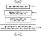
- FIG. 2 is a flowchart showing an operation example of the movement status presentation device 100 in the present embodiment.
- the movement status presentation method in the present embodiment is executed by at least one computer such as the movement status presentation device 100, and includes processing steps as shown in FIG.
- the movement status presentation method acquires movement information related to a plurality of moving objects including the current position (S101), and based on the movement information acquired in (S101), a plurality of common information among the plurality of moving objects.
- the positions of the plurality of moving bodies at each future time are predicted (S102), and the current positions of the plurality of moving bodies are displayed on the display unit using the movement information acquired in (S101) (S103). ), Based on the position predicted in (S102), the positions of the plurality of moving bodies at each future time are sequentially displayed in the future at the same display interval among the plurality of moving bodies. (S104).
- the display unit may be included in at least one computer that is the execution subject of the movement status presentation method, or may be included in another computer (not shown) that is communicably connected to the at least one computer. It may be.
- the embodiment of the present invention may be a program that causes at least one computer to execute the above-described movement status presentation method, or may be a computer-readable recording medium that records such a program. Good.
- movement information regarding a plurality of moving objects is acquired.
- the movement information includes the current position of each moving object. Based on this movement information, the positions of the plurality of moving bodies at each of the plurality of future times are predicted.
- the movement information further includes information necessary for predicting the future position of each moving body.
- This embodiment does not restrict the specific prediction method of the future position of the mobile body, and does not limit the specific content of the movement information.
- the future position of the mobile object can be predicted from the current position, the current speed, and the current traveling direction. In this case, the movement information only needs to include the current speed and the current traveling direction in addition to the current position.
- the future position of the moving body may be predicted in consideration of peripheral information related to the movement of the moving body.
- the future position of an automobile can be predicted by considering information on traffic lights, roads, and pedestrians in addition to movement information (speed and direction) of the automobile itself.
- the information on the traffic light can be acquired from the traffic signal by communication, and the information on the pedestrian can be acquired from a sensor or the like mounted on the automobile.
- a plurality of future times are set so as to be common among the plurality of moving objects. That is, the time granularity (unit time) of the future position of each mobile unit is set in common among all mobile units.
- the time interval between future times may be constant or different. For example, five future times are set at one minute intervals. In this case, when the current time is 15:30, 15:31, 15:32, 15:33, 15:34, and 15:35 are set as the plurality of future times.
- a plurality of future times may be set at arbitrary time intervals such as 15:33, 15:35, 15:40, and 15:50.
- the future time may be expressed as an absolute time as described above, or may be expressed as a relative time such as 5 minutes or 7 minutes later.
- the current position and the future position are displayed for each of the plurality of moving objects.
- the display of the position means that the viewer can output the two-dimensional position or the three-dimensional position of the moving body in a visible state, and specifically, an image displayed on the display unit. This is realized by displaying some display element (mark) at a display position corresponding to a certain two-dimensional position or a certain three-dimensional position based on the scale used.
- the position of the moving body at each future time is sequentially displayed toward the future at a display interval common to the plurality of moving bodies.
- Sequential display toward the future means that the positions of each future time are presented in order from the position of the future time closest to the present among the plurality of future times in the direction toward the future.
- the sequential display means that the position of the future time to be displayed at a certain display timing in the display interval and the position of the other future time are distinguished and presented. Therefore, the position of the future time other than the future time to be displayed at a certain display timing may not be displayed, or may be displayed in a manner different from the position of the future time to be displayed.
- the current position and the future position regarding a plurality of moving objects may be displayed as a three-dimensional image or a two-dimensional image.
- the position information of any one dimension is omitted.
- the position when the position is displayed as a three-dimensional image, the position may be displayed three-dimensionally using a three-dimensional computer graphic technique.
- the display interval may be constant or may be different between temporally adjacent future times.
- the display interval is set to a constant 3 seconds, and 15:31, 15:32, 15:33, 15:34, and 15:35 are set as the plurality of future times.
- the display interval is set such that the position at 15:31 is indicated after 3 seconds, the position at 15:32 is indicated after 6 seconds, and the position at 15:33 is indicated after 12 seconds. May be.
- this display interval is preferably set to a time obtained by shortening the time interval between future times that are temporally adjacent at a certain rate. In this way, the ratio between the display interval of the position from the present to the future and the time interval between temporally adjacent future times is constant, so that the movement status of each mobile object can be easily grasped.
- the positions of the plurality of moving bodies at each of a plurality of future times that are common among the plurality of moving bodies while displaying the current positions of the plurality of moving bodies on the display unit. Can be sequentially displayed toward the future at a display interval common to the plurality of moving bodies. Therefore, the viewer can grasp the current position of each moving body and the future position of each moving body at the same time. Further, for example, even when the movement paths of a plurality of moving bodies are approximated, the position of each moving body is indicated at the same timing for each common future time. It is possible to make it easy to visually recognize the arrival time difference between the moving bodies. That is, according to the present embodiment, the current and future positions of a plurality of moving objects can be presented with high visibility.
- Such a movement status presentation device 100 and a movement status presentation method may be mounted on the mobile body itself, or may be realized outside the mobile body like air traffic control.
- a flight status presentation device and a flight status presentation method for handling an aircraft as a moving body are exemplified as detailed embodiments.
- Each of the following detailed embodiments is applied to, for example, an air traffic control system.
- the contents of the following detailed embodiments are not limited to an aircraft, but can be applied to any moving body as described above.
- the aircraft can be read as other types of mobiles.
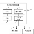
- FIG. 3 is a diagram conceptually illustrating a hardware configuration example of a flight status presentation device (hereinafter abbreviated as a presentation device) 1 in the first embodiment.
- the presentation device 1 is a so-called computer, and includes, for example, a CPU (Central Processing Unit) 2, a memory 3, an input / output interface (I / F) 4, a communication device 8, and the like that are connected to each other via a bus.
- the memory 3 is a RAM (Random Access Memory), a ROM (Read Only Memory), a hard disk, or the like.
- the communication device 8 communicates with other computers and devices.
- a portable recording medium or the like can be connected to the communication device 8.
- the input / output I / F 4 is connected to user interface devices such as the display device 6 and the input device 7.
- the display device 6 is a CPU 2 or a GPU (Graphics Processing Unit) (not shown) such as an LCD (Liquid Crystal Display), a CRT (Cathode Ray Tube) display, a video see-through type or an optical see-through type head mounted display (HMD). Z)) is a device that displays a screen corresponding to the drawing data processed.
- the input device 7 is a device that receives an input of a user operation such as a keyboard and a mouse.
- the display device 6 and the input device 7 may be integrated and realized as a touch panel. Note that the hardware configuration of the presentation device 1 is not limited.
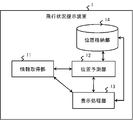
- FIG. 4 is a diagram conceptually illustrating a processing configuration example of the presentation device 1 in the first embodiment.
- the presentation device 1 in the first embodiment includes an information acquisition unit 11, a position prediction unit 12, a display processing unit 13, a position storage unit 14, and the like.
- Each of these processing units is realized, for example, by executing a program stored in the memory 3 by the CPU 2. Further, the program is installed from a portable recording medium such as a CD (Compact Disc) or a memory card or another computer on the network via the input / output I / F 4 or the communication device 8, and is installed in the memory 3. It may be stored.
- a portable recording medium such as a CD (Compact Disc) or a memory card or another computer on the network via the input / output I / F 4 or the communication device 8
- the information acquisition unit 11 corresponds to the information acquisition unit 101 described above.
- the information acquisition unit 11 acquires flight information regarding a plurality of aircraft including the current flight position.
- the flight information acquired by the information acquisition unit 11 includes information necessary for predicting the future flight position of each aircraft along with the current flight position with respect to a plurality of aircraft. In order to improve the prediction accuracy of the future flight position, it is desirable to obtain various information regarding flight of the aircraft such as ground speed, flight direction, flight plan, etc. as flight information.
- the flight information acquired by the information acquisition unit 11 is not limited.
- the presenting device 1 treats the aircraft that is the information source of the flight information acquired by the information acquisition unit 11, and presents the flight status of the aircraft.
- the position of the ground plane excluding the altitude is expressed as a geographical position.
- the geographical position is represented by two-dimensional information such as latitude and longitude.
- the position of the aircraft indicated by the geographical position and the altitude is referred to as a flight position.
- the flight position is represented by three-dimensional information.
- the information acquisition unit 11 acquires such flight information from other equipment groups such as various radars, anti-air communication devices, air traffic information systems, and the like.
- the flight information acquisition method is not limited to such a method.
- the information acquisition unit 11 may acquire the flight information from a GPS (Global Positioning System), may be acquired from a portable recording medium, or the user operates the input device 7 based on an input screen or the like. It may be acquired as input information.
- GPS Global Positioning System
- the acquisition timing of the flight information by the information acquisition unit 11 is not limited.
- Information on the current flight status, such as the current flight position, current ground speed, etc. in the flight information should be acquired in the shortest possible period, while frequently changing as in flight plans.
- the acquisition period of information that is not performed may be long.
- the position storage unit 14 stores the flight position for each future time for each aircraft.
- the position storage unit 14 stores the identification information (aircraft ID) of each aircraft and the flight position (geographic position and altitude) at each future time in a state of being associated with each other.
- the future time may be expressed in absolute time or relative time.
- the future time when expressed in absolute time does not mean a time that has not yet arrived at an arbitrary time, but means a future time at least when the flight position is predicted.
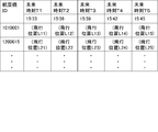
- FIG. 5 is a diagram illustrating an example of the position storage unit 14.
- the position storage unit 14 stores the flight position of each aircraft for each of the five future times.
- the number of future flight positions for each aircraft stored in the position storage unit 14 is fixed to five.
- the times indicated by the five fields from future times T1 to T5 are sequentially updated by the position prediction unit 12 described later. For example, when the time of the prediction processing timing by the position prediction unit 12 is 15:35, the future time T1 field indicates 15:38, the future time T2 field indicates 15:41, and the future time T3 field.
- the future time T4 field indicates 15:47
- the future time T5 field indicates 15:50
- the future time indicated by each field is updated.
- the number of future flight positions for each aircraft stored in the position storage unit 14 is limited to a predetermined number, so that the memory capacity used by the position storage unit 14 can be suppressed.
- future flight positions for each aircraft are exchanged between computers. Therefore, by limiting the number of future flight positions, Communication capacity can be reduced.
- time data is set in each future time field, but the time data itself may not be set in the position storage unit 14.
- the form of the position storage unit 14 is not limited to the example of FIG.
- the future time field indicates the year, month, day, hour and minute, and may be added sequentially with the passage of time.
- each time obtained by dividing 24 hours a day by a predetermined time interval (time granularity) may be set in advance as a future time.
- the flight position data at a time already passed on a certain day may be sequentially deleted from the position storage unit 14.
- a future time field for several years may be provided in advance.
- the position prediction unit 12 corresponds to the position prediction unit 102 described above.
- the position predicting unit 12 determines a predetermined number of future times according to the time of the prediction processing timing, predicts the flight positions of a plurality of aircraft at each determined future time, and positions at the predicted flight positions.
- the storage unit 14 is updated.
- the predetermined number corresponds to the number of future flight positions of each aircraft predicted by the position prediction unit 12.
- the predetermined number is determined in advance according to, for example, the interval of the prediction processing timing, the processing performance of the presentation device 1, the resource amount, and the like. This embodiment does not limit a specific method for predicting the future flight position of the aircraft.
- the position prediction unit 12 determines a predetermined number of future times that are common among the plurality of aircraft. Specifically, when the time interval between future times is fixed to be 5 minutes and the predetermined number is determined to be 6, the position predicting unit 12 starts from the time of the prediction processing timing. Minutes, 10 minutes, 15 minutes, 20 minutes, 25 minutes, and 30 minutes later are determined as future times. However, the determined time interval between future times may not be constant.
- the position predicting unit 12 may determine a predetermined number of future times starting from the time of the prediction processing timing. When the future time is determined in advance, the position predicting unit 12 selects a predetermined number of future times from the determined future times based on the time of the prediction processing timing. May be.
- the display processing unit 13 corresponds to the display processing unit 103 described above.
- the display processing unit 13 displays the current flight positions of a plurality of aircraft on the display device 6 using the flight information acquired by the information acquisition unit 11 and uses the information stored in the position storage unit 14.
- the flight positions of the plurality of aircraft at each future time are sequentially displayed on the display device 6 toward the future at a display interval common to the plurality of aircraft.
- the display interval by the display processing unit 13 does not depend on the interval of the prediction processing timing by the position prediction unit 12.
- the display processing unit 13 selects a future time to be displayed next at a common display interval among the plurality of aircrafts, extracts the flight positions of the plurality of aircrafts at the selected future time from the position storage unit 14, and extracts them.
- the flight positions of the plurality of aircraft thus displayed are displayed on the display device 6.
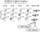
- FIG. 6 is a diagram illustrating an example of the relationship between the prediction processing timing and the display interval.
- the display interval is set to 5 seconds, and the time interval between future times is set to a fixed 5 minutes.
- the time interval of the prediction process timing is set to a display interval of 5 seconds or less, and it is assumed that the time for the flight position prediction process is as close to 0 as possible.
- future flight positions L11, L12, L13 and L14 starting from D1 are predicted, and at time D2 five seconds after time D1, four flight positions starting from D2 are predicted.
- Future flight positions L21, L22, L23, and L24 are predicted.
- the display processing unit 13 determines at what display timing the future time to be displayed at that time is the future time from the present to the future.
- the flight position of each aircraft at the future time is extracted from the position storage unit 14, and each flight position is displayed. Thereby, at each display processing timing, the flight position ahead of the predetermined time from the current flight position can be displayed with high accuracy.
- the display processing unit 13 may display the current flight position and the future flight position in a different manner so as to be distinguishable.
- a graphic indicating an aircraft is displayed at a display position corresponding to the current flight position
- a spherical graphic is displayed at a display position corresponding to a future flight position.
- the display processing unit 13 may also display other future flight positions.
- the flight positions L11, L22, and L33 displayed at each display timing are displayed in different display modes.
- the flight status presentation method according to the first embodiment will be described with reference to FIGS. 7 and 8.
- the presentation device 1 is an execution subject of each process, but the above-described processing units included in the presentation device 1 may be an execution subject.
- the flight status presentation method predicts the future flight position of each aircraft, displays the current flight position of each aircraft, and indicates the future flight position of each aircraft. Includes display.
- the presentation device 1 can execute each of these processes in parallel (independently). Hereinafter, prediction of future flight positions and display of future flight positions in the first embodiment will be described.
- FIG. 7 is a flowchart showing an operation example related to prediction of the future flight position of the presentation device 1 in the first embodiment.
- the presentation device 1 detects the arrival of the prediction processing timing (S71).
- the presentation device 1 waits until the prediction processing timing arrives (S71; NO).
- the prediction processing timing arrives (S71; YES)
- the presentation device 1 operates as follows.
- the presentation device 1 acquires flight information of a plurality of aircraft (S72).
- the flight information is as described above.
- the presentation device 1 determines a predetermined number of future times according to the time at that time (S73). Specifically, the presentation device 1 determines a plurality of future times having at least one predetermined time interval starting from the time of the prediction processing timing. When the time of the prediction processing timing is 15:30, for example, the presentation device 1 determines a plurality of future times such as 15:35, 15:40, 15:45, and 15:50. To do.
- the presentation device 1 predicts the flight positions of the plurality of aircraft at each of the predetermined number of future times determined in (S73) using the flight information acquired in (S72) (S74). ).
- the specific method for predicting the future flight position is as described for the position prediction unit 12.
- the presentation device 1 stores the flight position of each aircraft predicted in (S74) in the position storage unit 14 (S75).
- the presentation device 1 overwrites each flight position predicted in (S74) in the field corresponding to each future time.
- FIG. 8 is a flowchart showing an operation example related to the display of the future flight position of the presentation device 1 in the first embodiment.
- the presentation apparatus 1 detects the arrival of the next display timing at a display interval common to the plurality of aircrafts (S81).
- the presentation device 1 waits until the display timing arrives (S81; NO).
- the presenting device 1 operates as follows.
- the presentation device 1 displays the current flight position on the display device 6 as needed by executing (S101) and (S103) shown in FIG. 2 in addition to the operations shown in FIG.
- the presentation device 1 selects the future time corresponding to the display order N (S82).
- a plurality of future times that are common to all aircraft are ranked from the nearest to the future, and the display order N should be displayed at the current display timing in that order. Indicates the order of future times. Since the flight position of each aircraft at each future time is sequentially displayed toward the future, the display order N is incremented by one. In the example of FIG. 5, when the display order N is set to 3, the presentation device 1 selects 15:39 as the future time.
- the presentation device 1 extracts the flight position of each aircraft at the future time selected in (S82) from the position storage unit 14 (S83).
- the presentation device 1 causes the display device 6 to display the flight position of each aircraft extracted in (S83) (S84).
- the presentation device 1 updates the display order N for the next display timing (S85).
- the presentation device 1 increments the display order N by 1 as described above.
- the presentation apparatus 1 returns the display order N to the initial value (1) when the updated display order N exceeds the number of future flight positions stored in the position storage unit 14.
- the presentation device 1 displays the flight position at a future time corresponding to the updated display order N at the next display timing.
- the first embodiment for each prediction processing timing, a plurality of future times that are common among all the aircrafts are determined according to the time, and the flight positions at each future time are predicted, respectively.
- the target future time is selected from the plurality of future times, and the flight position at the selected future time is displayed.
- the predicted flight positions at a plurality of future times are stored in the position storage unit 14, the selected flight positions at the future time are extracted from the position storage unit 14, and the flight positions are displayed. In this way, independence between the prediction of the future flight position and the display of the future flight position is realized.
- a flight position at a future time based on the latest flight information can be displayed at each display timing. That is, according to the first embodiment, highly accurate future flight positions can be presented sequentially toward the future at a display interval common to all aircraft.
- FIG. 9 is a diagram conceptually illustrating a processing configuration example of the presentation device 1 in the second embodiment.
- the presentation device 1 in the second embodiment further includes a detection unit 15 in addition to the configuration of the first embodiment.
- the detection unit 15 is also realized by executing a program stored in the memory 3 by the CPU 2 as in the case of other processing units.
- the detection unit 15 detects a combination of aircraft and a warning position where the distance between the aircraft may be in a warning state based on the flight position predicted by the position prediction unit 12.
- the distance between aircrafts may be indicated by the distance in the three-dimensional space of the geographical position and altitude, or may be indicated by the distance in the two-dimensional space of only the geographical position, or in the two-dimensional space. May be indicated by both the distance and the altitude difference.
- the detection unit 15 detects a combination of aircraft that can be in a warning state by comparing a predetermined threshold based on the warning state determination rule and the distance between the aircrafts.
- the detection unit 15 monitors the flight position of each aircraft stored in the position storage unit 14 at any time, detects a combination of aircraft that is expected to have a distance between the aircraft below a predetermined threshold, and One warning position is determined based on the future flight position of each aircraft.
- the detected aircraft combination includes at least two aircraft.
- a specific method for determining whether or not the distance between the aircraft is in a warning state is not limited.
- the warning position is determined, for example, at the center position of the future flight position of each aircraft of the detected combination. However, it is desirable that one warning position be detected for the same combination of aircraft that can be in a warning state. When there are two aircraft that will be in a collision state or a minimum distance at a certain future time FT1, and the distance between the aircraft is predicted to be below a predetermined threshold at a future time FT2 before that future time FT1, It is not necessary to detect a plurality of warning positions between the future time FT1 and the future time FT2 and display a plurality of warning drawing elements for the same aircraft combination.
- the detection unit 15 detects one warning position based on each flight position at the future time FT1 that is the collision state or the minimum distance among the plurality of warning positions detected for the same aircraft combination. It may be. Note that the specific determination method is not limited as long as the warning position is determined using the future flight position of each aircraft of the detected combination.
- the detection unit 15 can further specify a future time when the distance between the aircraft can be in the warning state.
- the detection unit 15 extracts the future time corresponding to the flight position of each aircraft whose distance between the aircraft is equal to or less than a predetermined threshold from the position storage unit 14. can do.
- the detection unit 15 identifies the flight position of each aircraft whose distance between the aircraft is equal to or less than a predetermined threshold based on the position storage unit 14. And the data of the future time corresponding to the specified flight position can be acquired from another storage part.
- the display processing unit 13 displays the warning drawing element corresponding to the combination of aircraft detected by the detection unit 15 on the display device 6 on the display position corresponding to the geographical position of the warning position detected for the combination. It is displayed three-dimensionally.
- the display mode of the warning drawing element is not limited. However, when there are a plurality of aircraft combinations detected by the detection unit 15 and the geographical positions of the warning positions of the combinations are close, the plurality of warning drawing elements overlap, and the warning drawing elements Visibility deteriorates.
- the display processing unit 13 corresponds to the display device 6 with a plurality of warning drawing elements corresponding to a plurality of combinations of aircraft detected by the detection unit 15 to the geographical position of the warning position of each combination.
- Three-dimensional display is performed at display positions on the display position that are separated from each other in the altitude direction. That is, the display processing unit 13 displays each warning drawing element by shifting in the altitude direction.
- the detection unit 15 also detects the future time
- the display processing unit 13 displays the display position in the altitude direction of each of the plurality of warning drawing elements according to the future time detected by the detection unit 15. Can also be determined respectively.
- the display processing unit 13 displays the warning drawing element with the earlier future time of the warning state at a lower position. Thereby, it is possible to prevent a plurality of warning drawing elements from overlapping and deteriorating the visibility.
- the display processing unit 13 causes the display device 6 to display a linear drawing element connecting the current flight position of each aircraft included in the combination corresponding to the warning drawing element and the warning drawing element together with the warning drawing element. You can also. Thereby, the viewer can easily grasp the combination of the aircraft in the warning state as well as the position where the positional relationship between the aircraft can be in the warning state.
- the linear drawing element may be a solid line, a broken line, a one-dot chain line, or the like.
- the linear drawing element may not be directly coupled to the warning drawing element and each aircraft as long as the viewer can visually recognize the relationship between the warning drawing element and the combination of the aircraft.
- the altitude direction display position control of the warning drawing elements as described above may be performed for all warning drawing elements or only for some warning drawing elements.
- the display processing unit 13 determines whether or not the warning positions of a plurality of combinations of aircraft detected by the detection unit 15 are included in a predetermined range, and a plurality of combinations corresponding to the plurality of combinations included in the predetermined range.
- the display position control in the altitude direction can be applied only to the warning drawing element. In this way, only the warning drawing elements that are difficult to see when they are normally displayed are shifted in the altitude direction and displayed.
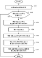
- FIG. 10 is a flowchart illustrating an operation example related to warning display of the presentation device 1 according to the second embodiment.
- the flight status presentation method in the second embodiment further includes a processing step related to the warning display shown in FIG. 10 together with the flight status presentation method in the first embodiment.
- the presentation apparatus 1 becomes an execution subject of each process, each above-mentioned process part contained in the presentation apparatus 1 may be an execution subject.
- the presentation device 1 calculates the distance between the aircraft for all pairs of all the aircraft based on the future flight position stored in the position storage unit 14 (S101). This calculation may be executed after the process (S75) shown in FIG. 7, or may be executed at any time independently of the prediction of the future flight position shown in FIG. The distance between the aircraft is as described above.
- the presentation device 1 determines whether there is a distance between aircrafts that can be in a warning state based on the calculation result in (S101) (S102). For example, the presentation device 1 identifies the distance between the aircraft that may be in a warning state by comparing each distance calculated in (S101) with a predetermined threshold.
- a specific determination method for determining whether or not the distance between aircrafts is in a warning state is not limited.
- the presenting device 1 ends the process when there is no distance that can be in a warning state (S102; NO). On the other hand, when there is a distance that can be in a warning state (S102; YES), the presentation device 1 detects a combination of aircraft corresponding to the distance (S103).
- the presentation device 1 detects a warning position that can be in a warning state (S104).
- the presentation device 1 determines the warning position based on the flight position of each aircraft of the combination detected in (S103).
- the warning position determination (detection) method is also as described above.
- the presentation device 1 specifies a future time that can be in a warning state (S105).
- the presentation apparatus 1 can specify the future time corresponding to the flight position of each aircraft of the combination detected in (S103).
- the presentation device 1 determines the display position in the altitude direction for each combination of aircraft detected in (S103) according to the future time specified in (S105) (S106). For example, the presentation device 1 determines the lower display position as the combination of the aircrafts whose future time specified in (S105) is earlier.
- the presentation device 1 displays, on the display device 6, each warning drawing element corresponding to each combination of aircraft detected in (S103), a display position corresponding to the geographical position of the warning position detected in (S104). It is displayed at the display position in the altitude direction that is above and determined in (S106) (S107). Furthermore, the presentation device 1 further causes the display device 6 to display a linear drawing element that connects each warning drawing element and the current flight position of each aircraft in a combination corresponding to the warning drawing element.
- the processing steps related to the warning display included in the flight status presentation method in the second embodiment are not limited to the example of FIG.
- the display position in the altitude direction of each warning drawing element may be determined without depending on the future time when the warning state can be set. In this case, (S105) is not necessary, and in (S106), the display position in the altitude direction of each warning drawing element is determined according to a predetermined rule without depending on the future time.
- the presentation device 1 may apply the altitude direction display position control only to a plurality of warning drawing elements in which the warning position detected in (S104) is included in a predetermined range.
- the presentation apparatus 1 determines whether or not there is a plurality of combinations in which the warning position detected in (S104) is included in the predetermined range between (S104) and (S105). It is sufficient to determine whether or not to execute (S105) and (S106) according to the determination result.
- the display position in the altitude direction of each warning drawing element is determined according to the future time that can be in a warning state. Accordingly, it is possible to present a plurality of warning drawing elements with high visibility, and it is also possible to present the context of time that can be in a warning state.
- a warning drawing element is displayed at a warning position that can be in a warning state, and a linear drawing element that connects the current flight position of each aircraft in a combination that can be in the warning state and the warning drawing element is displayed. Is done. This makes it easy for a person who sees the current flight position of each aircraft involved in the warning together with the warning position to be grasped.
- the altitude direction display position control is applied only to a plurality of warning drawing elements corresponding to a plurality of combinations included in the predetermined range.
- the presentation device 1 naturally has a function of deleting the displayed warning drawing element.
- the detection unit 15 detects that the distance between the aircraft of the combination determined to be in a warning state is greater than a predetermined threshold.
- the display processing unit 13 detects that the distance between the aircrafts in the combination is greater than a predetermined threshold, the display processing unit 13 deletes the warning drawing element corresponding to the combination.
- the predetermined threshold used for canceling the warning state is set to a value larger than the predetermined threshold used for determining that the warning state can be set. Thereby, it is possible to prevent the display and deletion of the warning drawing element from being repeated unnecessarily.
- the presentation device 1 displays the flight position of the aircraft on the display device 6 connected to its input / output I / F 4.
- the presentation device 1 is connected to another computer.
- the flight position and the like can be displayed on the display device.
- the presentation device 1 transmits drawing data to another computer via the communication device 8.
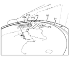
- FIG. 11 is a diagram showing a display example of the current flight position and the future flight position of one aircraft in the embodiment.
- the presentation device 1 displays a map image B ⁇ b> 1 representing a geographical position, and a azimuth image B ⁇ b> 2 that surrounds the map image B ⁇ b> 1 and indicates a azimuth, and displays these images.
- the present flight position and future flight position of one aircraft are displayed three-dimensionally in a superimposed manner.
- the presentation apparatus 1 displays an aircraft image PC as a drawing element indicating the current flight position, and displays a spherical image group PF as a drawing element indicating the future flight position.
- the presentation device 1 displays a spherical image indicating a flight position at a future time displayed at a display timing at a common display interval among a plurality of aircrafts in a manner different from a spherical image indicating a flight position at another future time.
- the spherical image PF2 is displayed in a mode different from other spherical images (PF1, PF3, PF4, etc.).
- the viewer can visually recognize the spherical image displayed in a specific manner as moving toward the future at a common display interval among a plurality of aircraft.
- Each display position of each spherical image corresponds to a flight position at each future time that is common among the plurality of aircraft.
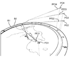
- FIG. 12 is a diagram illustrating a display example of current flight positions and future flight positions of a plurality of (four) aircrafts in the embodiment.
- the presentation device 1 displays the current flight positions of a plurality of aircraft as aircraft images PC1, PC2, PC3, and PC4. Then, at the display timing shown in FIG. 12, the presentation device 1 differs in flight position (spherical image PF21, PF22, PF23, PF24) at the second future time from the present with respect to each aircraft from other flight positions. Each is displayed in a manner.
- the viewer can easily grasp the flight position of each aircraft at the future time (second future time from the present) common among these four aircrafts by viewing the spherical images PF21, PF22, PF23, and PF24. can do.
- the broken line shown by FIG.11 and FIG.12 has shown the route pattern prescribed
- FIG. 13 is a diagram showing an example of warning display in the embodiment.
- balloon-shaped images AP1 and AP2 are displayed as warning drawing elements.
- the presentation device 1 displays two warning drawing elements AP1 and AP2 corresponding to two combinations of aircraft that may be in a warning state on a display position corresponding to the geographical position of the warning position of each combination. To shift the altitude direction and display it three-dimensionally.
- the presentation device 1 displays the linear drawing elements LP1 and LP2 that connect the warning drawing element AP1 and the current flight positions PC10 and PC11 of the corresponding combinations of the aircraft, respectively, and the warning drawing element AP2 and the corresponding drawing element AP2.
- Linear drawing elements LP3 and LP4 that connect the current flight positions PC12 and PC13 of each aircraft in the combination are displayed. Thereby, even if the warning position is approximated, deterioration of the visibility of each warning drawing element can be prevented, and the combination of aircraft corresponding to each warning state can be easily grasped.
Landscapes
- Physics & Mathematics (AREA)
- General Physics & Mathematics (AREA)
- Engineering & Computer Science (AREA)
- Aviation & Aerospace Engineering (AREA)
- Traffic Control Systems (AREA)
- Navigation (AREA)
- Radar, Positioning & Navigation (AREA)
- Remote Sensing (AREA)
Abstract
Description
以下、上述の実施形態について更に詳細を説明する。以下には、移動体として航空機を扱う飛行状況提示装置及び飛行状況提示方法が詳細実施形態として例示される。以下の各詳細実施形態は、例えば、航空管制システムに適用される。但し、以下の各詳細実施形態の内容は、移動体を航空機に限定するものではなく、上述のようにあらゆる移動体に適用可能である。以下の各詳細実施形態において、航空機は、他の種類の移動体に読み替えることができる。
〔装置構成〕
図3は、第1実施形態における飛行状況提示装置(以降、提示装置と略称する)1のハードウェア構成例を概念的に示す図である。第1実施形態における提示装置1は、いわゆるコンピュータであり、例えば、バスで相互に接続される、CPU(Central Processing Unit)2、メモリ3、入出力インタフェース(I/F)4、通信装置8等を有する。メモリ3は、RAM(Random Access Memory)、ROM(Read Only Memory)、ハードディスク等である。通信装置8は、他のコンピュータや機器と通信を行う。通信装置8には、可搬型記録媒体等も接続され得る。
図4は、第1実施形態における提示装置1の処理構成例を概念的に示す図である。第1実施形態における提示装置1は、情報取得部11、位置予測部12、表示処理部13、位置格納部14等を有する。これら各処理部は、例えば、CPU2によりメモリ3に格納されるプログラムが実行されることにより実現される。また、当該プログラムは、例えば、CD(Compact Disc)、メモリカード等のような可搬型記録媒体やネットワーク上の他のコンピュータから入出力I/F4又は通信装置8を介してインストールされ、メモリ3に格納されてもよい。
以下、第1実施形態における飛行状況提示方法について図7及び図8を用いて説明する。以下の説明では、提示装置1が各工程の実行主体となるが、提示装置1に含まれる上述の各処理部が実行主体となってもよい。
上述したように第1実施形態では、予測処理タイミング毎に、その時刻に応じて、全航空機間で共通の複数の未来時刻が決定され、各未来時刻の飛行位置がそれぞれ予測され、全航空機間で共通の表示間隔での表示タイミング毎に、当該複数の未来時刻の中から対象の未来時刻が選択され、選択された未来時刻の飛行位置が表示される。第1実施形態では、予測された複数の未来時刻の飛行位置が位置格納部14に格納され、選択された未来時刻の飛行位置が位置格納部14から抽出され、その飛行位置が表示される。このようにして、未来の飛行位置の予測と、未来の飛行位置の表示との独立性が実現されている。第1実施形態によれば、この独立性により、各表示タイミングにおいて、最新の飛行情報に基づく未来時刻の飛行位置を表示させることができる。即ち、第1実施形態によれば、全航空機で共通の表示間隔で未来へ向けて順次、高精度な未来の飛行位置を提示することができる。
第2実施形態では、第1実施形態の機能に加えて、航空機間の位置関係に応じた警告表示機能が実現される。以下、第2実施形態における提示装置1について、第1実施形態と異なる内容を中心に説明する。以下の説明では、第1実施形態と同様の内容については適宜省略する。
図9は、第2実施形態における提示装置1の処理構成例を概念的に示す図である。第2実施形態における提示装置1は、第1実施形態の構成に加えて、検出部15を更に有する。検出部15についても、他の処理部と同様に、CPU2によりメモリ3に格納されるプログラムが実行されることにより実現される。
以下、第2実施形態における飛行状況提示方法について図10を用いて第1実施形態と異なる内容を中心に説明する。以下の説明では、第1実施形態と同様の内容については適宜省略する。図10は、第2実施形態における提示装置1の、警告表示に関する動作例を示すフローチャートである。第2実施形態における飛行状況提示方法は、第1実施形態における飛行状況提示方法と共に、図10に示される警告表示に関する処理工程を更に含む。また、以下の説明では、提示装置1が各工程の実行主体となるが、提示装置1に含まれる上述の各処理部が実行主体となってもよい。
第2実施形態では、予測される未来の飛行位置に基づいて、航空機間の距離が警告状態となり得る航空機の組み合わせ及び警告位置が検出され、この検出された航空機の複数の組み合わせに対応する複数の警告描画要素が、各組み合わせの警告位置の地理的位置に相当する表示位置上で高度方向に離間されて3次元的に表示される。これにより、第2実施形態によれば、警告位置の地理的位置が近い航空機の組み合わせが複数存在する場合であっても、それら複数の組み合わせに対応する複数の警告描画要素を視認性よく提示することができる。
上述の第2実施形態では、警告描画要素の表示についてのみ説明されたが、提示装置1は、表示されている警告描画要素を消去する機能も当然に有する。この場合、検出部15は、警告状態となり得ると判定された航空機の組み合わせについて、その組み合わせの航空機間の距離が所定閾値よりも大きくなることを検出する。表示処理部13は、当該組み合わせの航空機間の距離が所定閾値よりも大きくなったことの検出により、その組み合わせに対応する警告描画要素を消去する。この場合、警告状態を解除するために用いられる所定閾値は、警告状態となり得ると判定するために用いられる所定閾値よりも大きい値に設定されることが望ましい。これにより、警告描画要素の表示及び消去が不必要に繰り返されるのを防ぐことができる。
上述の各実施形態では、提示装置1は、自身の入出力I/F4に接続される表示装置6に航空機の飛行位置などを表示させたが、提示装置1は、他のコンピュータに接続される表示装置に当該飛行位置などを表示させることもできる。この場合には、例えば、提示装置1は、描画データを通信装置8を介して他のコンピュータに送信する。
Claims (13)
- 現在位置を含む複数の移動体に関する移動情報を取得する情報取得部と、
前記情報取得部により取得される移動情報に基づいて、前記複数の移動体間で共通の複数の未来時刻の各々における、前記複数の移動体の位置をそれぞれ予測する位置予測部と、
前記情報取得部により取得される移動情報を用いて、前記複数の移動体の現在位置を表示部に表示させ、かつ、前記位置予測部により予測される位置に基づいて、前記複数の移動体間で共通の表示間隔で、前記各未来時刻における、前記複数の移動体の位置を未来へ向けて順次、該表示部に表示させる表示処理部と、
を備える移動状況提示装置。 - 各移動体に関し、未来時刻毎の位置をそれぞれ格納する位置格納部、
を更に備え、
前記位置予測部は、予測処理タイミングの時刻に応じて、所定個数の未来時刻を決定し、該決定された各未来時刻における前記複数の移動体の位置をそれぞれ予測し、該予測された位置で、前記位置格納部を更新し、
前記表示処理部は、前記表示間隔で次に表示させるべき未来時刻を選択し、該選択された未来時刻における前記複数の移動体の位置を前記位置格納部から抽出し、該抽出された前記複数の移動体の位置を前記表示部に表示させる、
請求項1に記載の移動状況提示装置。 - 前記位置予測部により予測される位置に基づいて、移動体間の距離が警告状態となり得る移動体の組み合わせ及び警告位置を検出する検出部、
を更に備え、
前記表示処理部は、前記表示部に、前記検出部で検出される移動体の複数の組み合わせに対応する複数の警告描画要素を、該各組み合わせの警告位置の地理的位置に相当する表示位置上の、高度方向に相互に離れた表示位置に、3次元的に表示させる、
請求項1又は2に記載の移動状況提示装置。 - 前記検出部は、移動体間の距離が前記警告状態となり得る未来時刻を更に特定し、
前記表示処理部は、前記検出部で特定される未来時刻に応じて、前記複数の警告描画要素の各々の、高度方向における表示位置をそれぞれ決定する、
請求項3に記載の移動状況提示装置。 - 前記表示処理部は、前記検出部で検出される移動体の複数の組み合わせの警告位置が所定範囲に含まれるか否かを判定し、該所定範囲に含まれる複数の組み合わせに対応する複数の警告描画要素のみに、高度方向の表示位置制御を適用する、
請求項3又は4に記載の移動状況提示装置。 - 前記位置予測部により予測される位置に基づいて、移動体間の距離が警告状態となり得る移動体の組み合わせ及び警告位置を検出する検出部、
を更に備え、
前記表示処理部は、前記検出部で検出される移動体の組み合わせに対応する警告描画要素を、該組み合わせの警告位置の地理的位置に相当する表示位置上に表示させ、かつ、該警告描画要素に対応する組み合わせに含まれる各移動体の現在位置と該警告描画要素とを結ぶ線形描画要素を前記表示部に表示させる、
請求項1から5のいずれか1項に記載の移動状況提示装置。 - 少なくとも1つのコンピュータにより実行される移動状況提示方法において、
現在位置を含む複数の移動体に関する移動情報を取得し、
前記取得された移動情報に基づいて、前記複数の移動体間で共通の複数の未来時刻の各々における、前記複数の移動体の位置をそれぞれ予測し、
前記取得された移動情報を用いて、前記複数の移動体の現在位置を表示部に表示させ、
前記予測された位置に基づいて、前記複数の移動体間で共通の表示間隔で、前記各未来時刻における、前記複数の移動体の位置を未来へ向けて順次、前記表示部に表示させる、
ことを含む移動状況提示方法。 - 各移動体に関し未来時刻毎の位置をそれぞれ格納する位置格納部を、前記予測された位置で更新する、
ことを更に含み、
前記予測は、予測処理タイミングの時刻に応じて、所定個数の未来時刻を決定し、該決定された各未来時刻における前記複数の移動体の位置をそれぞれ予測し、
前記各未来時刻における位置の表示は、前記表示間隔で次に表示させるべき未来時刻を選択し、前記選択された未来時刻における前記複数の移動体の位置を前記位置格納部から抽出し、該抽出された前記複数の移動体の位置を前記表示部に表示させる、
請求項7に記載の移動状況提示方法。 - 前記予測された位置に基づいて、移動体間の距離が警告状態となり得る移動体の組み合わせ及び警告位置を検出し、
前記検出された移動体の複数の組み合わせに対応する複数の警告描画要素を、前記表示部に、該各組み合わせの警告位置の地理的位置に相当する表示位置上の、高度方向に相互に離れた表示位置に、3次元的に表示させる、
ことを更に含む請求項7又は8に記載の移動状況提示方法。 - 移動体間の距離が前記警告状態となり得る未来時刻を特定し、
前記特定された未来時刻に応じて、前記複数の警告描画要素の各々の、高度方向における表示位置をそれぞれ決定する、
ことを更に含む請求項9に記載の移動状況提示方法。 - 前記検出された移動体の複数の組み合わせの警告位置が所定範囲に含まれるか否かを判定する、
ことを更に含み、
前記警告描画要素の表示は、前記所定範囲に含まれる複数の組み合わせに対応する複数の警告描画要素のみに、高度方向の表示位置制御を適用する、
請求項9又は10に記載の移動状況提示方法。 - 前記予測された位置に基づいて、移動体間の距離が警告状態となり得る移動体の組み合わせ及び警告位置を検出し、
前記検出された移動体の組み合わせに対応する警告描画要素を、前記表示部に、該組み合わせの警告位置の地理的位置に相当する表示位置上に表示させ、
前記警告描画要素に対応する組み合わせに含まれる各移動体の現在位置と前記警告描画要素とを結ぶ線形描画要素を前記表示部に表示させる、
ことを更に含む請求項7から11のいずれか1項に記載の移動状況提示方法。 - 請求項7から12のいずれか1項に記載の移動状況提示方法を少なくとも1つのコンピュータに実行させるプログラム。
Priority Applications (4)
| Application Number | Priority Date | Filing Date | Title |
|---|---|---|---|
| CN201480051693.5A CN105580062A (zh) | 2013-09-19 | 2014-05-28 | 移动状态呈现设备和移动状态呈现方法 |
| HK16109531.9A HK1221547A1 (zh) | 2013-09-19 | 2014-05-28 | 移动状态呈现设备和移动状态呈现方法 |
| US15/021,852 US9892645B2 (en) | 2013-09-19 | 2014-05-28 | Movement state presentation device and movement state presentation method |
| JP2015537575A JP6281957B2 (ja) | 2013-09-19 | 2014-05-28 | 移動状況提示装置及び移動状況提示方法 |
Applications Claiming Priority (2)
| Application Number | Priority Date | Filing Date | Title |
|---|---|---|---|
| JP2013-194675 | 2013-09-19 | ||
| JP2013194675 | 2013-09-19 |
Publications (1)
| Publication Number | Publication Date |
|---|---|
| WO2015040893A1 true WO2015040893A1 (ja) | 2015-03-26 |
Family
ID=52688556
Family Applications (1)
| Application Number | Title | Priority Date | Filing Date |
|---|---|---|---|
| PCT/JP2014/064110 Ceased WO2015040893A1 (ja) | 2013-09-19 | 2014-05-28 | 移動状況提示装置及び移動状況提示方法 |
Country Status (5)
| Country | Link |
|---|---|
| US (1) | US9892645B2 (ja) |
| JP (1) | JP6281957B2 (ja) |
| CN (1) | CN105580062A (ja) |
| HK (1) | HK1221547A1 (ja) |
| WO (1) | WO2015040893A1 (ja) |
Cited By (4)
| Publication number | Priority date | Publication date | Assignee | Title |
|---|---|---|---|---|
| CN105825715A (zh) * | 2016-03-14 | 2016-08-03 | 福建北斗星河通信有限公司 | 一种基于移动终端的船舶防碰撞的优化方法及系统 |
| WO2018020744A1 (ja) * | 2016-07-29 | 2018-02-01 | Necソリューションイノベータ株式会社 | 移動体操縦システム、操縦シグナル送信システム、移動体操縦方法、プログラム、および記録媒体 |
| JP2021500681A (ja) * | 2017-10-25 | 2021-01-07 | ヴィナーティ ソチエタ ア レスポンサビリタ リミタータ | 航空機の交通管制方法 |
| US11415980B2 (en) | 2016-07-29 | 2022-08-16 | Nec Solution Innovators, Ltd. | Moving object operation system, operation signal transmission system, moving object operation method, program, and recording medium |
Families Citing this family (8)
| Publication number | Priority date | Publication date | Assignee | Title |
|---|---|---|---|---|
| WO2016149039A1 (en) * | 2015-03-17 | 2016-09-22 | Sikorsky Aircraft Corporation | Trajectory control of a vehicle |
| JP6690382B2 (ja) * | 2016-04-22 | 2020-04-28 | 富士通株式会社 | 航跡データ表示プログラム、航跡データ表示方法および航跡データ表示装置 |
| CN108696558B (zh) * | 2017-04-11 | 2022-04-26 | 腾讯科技(深圳)有限公司 | 位置信息处理方法和装置 |
| CN111033429A (zh) * | 2017-09-11 | 2020-04-17 | 深圳市大疆创新科技有限公司 | 用于支持操作对象的安全操作的系统和方法 |
| US11562006B2 (en) | 2017-10-03 | 2023-01-24 | Ohio State Innovation Foundation | Apparatus and method for interactive analysis of aviation data |
| CN109933396A (zh) * | 2019-02-22 | 2019-06-25 | 上海市建设工程监理咨询有限公司 | 一种建设工程监理工程测量系统 |
| US12198546B1 (en) * | 2021-09-30 | 2025-01-14 | Lytx, Inc. | Context based alert filtering using ranked risk from vehicle events and/or an accident database |
| US12217606B1 (en) | 2021-09-30 | 2025-02-04 | Lytx, Inc. | Timing or zone alert determination from vehicle events and/or an accident database |
Citations (7)
| Publication number | Priority date | Publication date | Assignee | Title |
|---|---|---|---|---|
| JPH09251600A (ja) * | 1996-03-18 | 1997-09-22 | Commuter Herikoputa Senshin Gijutsu Kenkyusho:Kk | 航空機衝突防止装置 |
| JPH11203600A (ja) * | 1998-01-19 | 1999-07-30 | Nec Corp | 飛行状況表示方法 |
| JP2003132499A (ja) | 2001-10-24 | 2003-05-09 | Electronic Navigation Research Institute | 航空管制用表示装置における航空機位置表示方法 |
| JP2008267955A (ja) * | 2007-04-19 | 2008-11-06 | Pioneer Electronic Corp | ナビゲーション装置、引き出し表示方法及び引き出し表示プログラム |
| US20100060511A1 (en) * | 2008-09-09 | 2010-03-11 | Thales | Viewing device for aircraft comprising means of displaying trajectories of intruders presenting a risk of collision in all the space surrounding the aircraft |
| JP2010152875A (ja) * | 2008-11-19 | 2010-07-08 | Furuno Electric Co Ltd | 航海支援装置 |
| JP2012127707A (ja) * | 2010-12-14 | 2012-07-05 | Alpine Electronics Inc | 施設アイコン表示調整機能付ナビゲーション装置 |
Family Cites Families (4)
| Publication number | Priority date | Publication date | Assignee | Title |
|---|---|---|---|---|
| US5872526A (en) * | 1996-05-23 | 1999-02-16 | Sun Microsystems, Inc. | GPS collision avoidance system |
| US6683541B2 (en) * | 1999-01-21 | 2004-01-27 | Honeywell International Inc. | Vertical speed indicator and traffic alert collision avoidance system |
| WO2002004973A2 (en) * | 2000-07-10 | 2002-01-17 | United Parcel Service Of America, Inc. | Method for determining conflicting paths between mobile airborne vehicles and associated system and computer software program product |
| US6744396B2 (en) * | 2001-07-20 | 2004-06-01 | Aviation Communication & Surveillance Systems Llc | Surveillance and collision avoidance system with compound symbols |
-
2014
- 2014-05-28 HK HK16109531.9A patent/HK1221547A1/zh unknown
- 2014-05-28 CN CN201480051693.5A patent/CN105580062A/zh active Pending
- 2014-05-28 WO PCT/JP2014/064110 patent/WO2015040893A1/ja not_active Ceased
- 2014-05-28 JP JP2015537575A patent/JP6281957B2/ja active Active
- 2014-05-28 US US15/021,852 patent/US9892645B2/en active Active
Patent Citations (7)
| Publication number | Priority date | Publication date | Assignee | Title |
|---|---|---|---|---|
| JPH09251600A (ja) * | 1996-03-18 | 1997-09-22 | Commuter Herikoputa Senshin Gijutsu Kenkyusho:Kk | 航空機衝突防止装置 |
| JPH11203600A (ja) * | 1998-01-19 | 1999-07-30 | Nec Corp | 飛行状況表示方法 |
| JP2003132499A (ja) | 2001-10-24 | 2003-05-09 | Electronic Navigation Research Institute | 航空管制用表示装置における航空機位置表示方法 |
| JP2008267955A (ja) * | 2007-04-19 | 2008-11-06 | Pioneer Electronic Corp | ナビゲーション装置、引き出し表示方法及び引き出し表示プログラム |
| US20100060511A1 (en) * | 2008-09-09 | 2010-03-11 | Thales | Viewing device for aircraft comprising means of displaying trajectories of intruders presenting a risk of collision in all the space surrounding the aircraft |
| JP2010152875A (ja) * | 2008-11-19 | 2010-07-08 | Furuno Electric Co Ltd | 航海支援装置 |
| JP2012127707A (ja) * | 2010-12-14 | 2012-07-05 | Alpine Electronics Inc | 施設アイコン表示調整機能付ナビゲーション装置 |
Cited By (8)
| Publication number | Priority date | Publication date | Assignee | Title |
|---|---|---|---|---|
| CN105825715A (zh) * | 2016-03-14 | 2016-08-03 | 福建北斗星河通信有限公司 | 一种基于移动终端的船舶防碰撞的优化方法及系统 |
| CN105825715B (zh) * | 2016-03-14 | 2019-04-12 | 福建北斗星河通信有限公司 | 一种基于移动终端的船舶防碰撞的优化方法及系统 |
| WO2018020744A1 (ja) * | 2016-07-29 | 2018-02-01 | Necソリューションイノベータ株式会社 | 移動体操縦システム、操縦シグナル送信システム、移動体操縦方法、プログラム、および記録媒体 |
| JPWO2018020744A1 (ja) * | 2016-07-29 | 2019-05-16 | Necソリューションイノベータ株式会社 | 移動体操縦システム、操縦シグナル送信システム、移動体操縦方法、プログラム、および記録媒体 |
| US11415980B2 (en) | 2016-07-29 | 2022-08-16 | Nec Solution Innovators, Ltd. | Moving object operation system, operation signal transmission system, moving object operation method, program, and recording medium |
| US11467572B2 (en) | 2016-07-29 | 2022-10-11 | NEC Solution Innovations, Ltd. | Moving object operation system, operation signal transmission system, moving object operation method, program, and recording medium |
| JP2021500681A (ja) * | 2017-10-25 | 2021-01-07 | ヴィナーティ ソチエタ ア レスポンサビリタ リミタータ | 航空機の交通管制方法 |
| JP7332166B2 (ja) | 2017-10-25 | 2023-08-23 | ヴィナーティ ソチエタ ア レスポンサビリタ リミタータ | 航空機の交通管制方法 |
Also Published As
| Publication number | Publication date |
|---|---|
| HK1221547A1 (zh) | 2017-06-02 |
| CN105580062A (zh) | 2016-05-11 |
| US20160232793A1 (en) | 2016-08-11 |
| JPWO2015040893A1 (ja) | 2017-03-02 |
| US9892645B2 (en) | 2018-02-13 |
| JP6281957B2 (ja) | 2018-02-21 |
Similar Documents
| Publication | Publication Date | Title |
|---|---|---|
| JP6281957B2 (ja) | 移動状況提示装置及び移動状況提示方法 | |
| CN107346137B (zh) | 车辆的基于网络的存储器和用于优化车辆路线规划的基础设施数据 | |
| EP1943571B1 (en) | System and method for performing 4-dimensional navigation | |
| EP2431960B1 (en) | Ground navigational display, system and method displaying buildings in three-dimensions | |
| US9852493B2 (en) | Methods and systems for displaying a vertical profile for an aircraft procedure with nonuniform scaling | |
| EP1897081B1 (en) | Perspective view conformal traffic targets display | |
| EP3260817A1 (en) | Method, apparatus and computer program product for a navigation user interface | |
| US10540895B2 (en) | Management of mobile objects | |
| US11408747B2 (en) | In-vehicle apparatus and information presentation method | |
| JP7267796B2 (ja) | 経路提示方法及び経路提示装置 | |
| US20210302195A1 (en) | Information processing device, path guidance device, information processing method, and computer-readable storage medium | |
| EP3742118A1 (en) | Systems and methods for managing a vision system display of an aircraft | |
| US10565883B2 (en) | Systems and methods for managing practice airspace | |
| CN108917786A (zh) | 用于指示基于时间的要求的显示系统和方法 | |
| US20220197893A1 (en) | Aerial vehicle and edge device collaboration for visual positioning image database management and updating | |
| CN105043374A (zh) | 用于显示上下文敏感注释的系统和方法 | |
| US10788325B1 (en) | Systems and methods for hybrid graph and grid three-dimensional routing | |
| EP2927639A1 (en) | Avionics system and method for displaying optimized ownship position on a navigation display | |
| JP7488063B2 (ja) | 都市航空ビークルの航法性能 | |
| EP3508824A1 (en) | Water encoding for vision systems | |
| US11200749B2 (en) | Systems and methods of augmented reality visualization based on sensor data | |
| JPWO2018179599A1 (ja) | 情報提供装置 | |
| EP4000982B1 (en) | Systems and methods of augmented reality visualization based on sensor data | |
| US10102684B2 (en) | On-board device and route interpolating method therefor | |
| EP4379697A1 (en) | Systems and methods for implementing condition-based actions in an aircraft |
Legal Events
| Date | Code | Title | Description |
|---|---|---|---|
| WWE | Wipo information: entry into national phase |
Ref document number: 201480051693.5 Country of ref document: CN |
|
| 121 | Ep: the epo has been informed by wipo that ep was designated in this application |
Ref document number: 14845231 Country of ref document: EP Kind code of ref document: A1 |
|
| ENP | Entry into the national phase |
Ref document number: 2015537575 Country of ref document: JP Kind code of ref document: A |
|
| REEP | Request for entry into the european phase |
Ref document number: 2014845231 Country of ref document: EP |
|
| WWE | Wipo information: entry into national phase |
Ref document number: 2014845231 Country of ref document: EP |
|
| WWE | Wipo information: entry into national phase |
Ref document number: 15021852 Country of ref document: US |
|
| NENP | Non-entry into the national phase |
Ref country code: DE |