WO2015040887A1 - Endoscope - Google Patents
Endoscope Download PDFInfo
- Publication number
- WO2015040887A1 WO2015040887A1 PCT/JP2014/063106 JP2014063106W WO2015040887A1 WO 2015040887 A1 WO2015040887 A1 WO 2015040887A1 JP 2014063106 W JP2014063106 W JP 2014063106W WO 2015040887 A1 WO2015040887 A1 WO 2015040887A1
- Authority
- WO
- WIPO (PCT)
- Prior art keywords
- diaphragm
- adapter
- light receiving
- unit
- lens
- Prior art date
- Legal status (The legal status is an assumption and is not a legal conclusion. Google has not performed a legal analysis and makes no representation as to the accuracy of the status listed.)
- Ceased
Links
Images


Classifications
-
- A—HUMAN NECESSITIES
- A61—MEDICAL OR VETERINARY SCIENCE; HYGIENE
- A61B—DIAGNOSIS; SURGERY; IDENTIFICATION
- A61B1/00—Instruments for performing medical examinations of the interior of cavities or tubes of the body by visual or photographical inspection, e.g. endoscopes; Illuminating arrangements therefor
- A61B1/00064—Constructional details of the endoscope body
- A61B1/00071—Insertion part of the endoscope body
- A61B1/0008—Insertion part of the endoscope body characterised by distal tip features
- A61B1/00096—Optical elements
-
- A—HUMAN NECESSITIES
- A61—MEDICAL OR VETERINARY SCIENCE; HYGIENE
- A61B—DIAGNOSIS; SURGERY; IDENTIFICATION
- A61B1/00—Instruments for performing medical examinations of the interior of cavities or tubes of the body by visual or photographical inspection, e.g. endoscopes; Illuminating arrangements therefor
- A61B1/00064—Constructional details of the endoscope body
- A61B1/00071—Insertion part of the endoscope body
- A61B1/0008—Insertion part of the endoscope body characterised by distal tip features
- A61B1/00101—Insertion part of the endoscope body characterised by distal tip features the distal tip features being detachable
-
- A—HUMAN NECESSITIES
- A61—MEDICAL OR VETERINARY SCIENCE; HYGIENE
- A61B—DIAGNOSIS; SURGERY; IDENTIFICATION
- A61B1/00—Instruments for performing medical examinations of the interior of cavities or tubes of the body by visual or photographical inspection, e.g. endoscopes; Illuminating arrangements therefor
- A61B1/00064—Constructional details of the endoscope body
- A61B1/0011—Manufacturing of endoscope parts
-
- A—HUMAN NECESSITIES
- A61—MEDICAL OR VETERINARY SCIENCE; HYGIENE
- A61B—DIAGNOSIS; SURGERY; IDENTIFICATION
- A61B1/00—Instruments for performing medical examinations of the interior of cavities or tubes of the body by visual or photographical inspection, e.g. endoscopes; Illuminating arrangements therefor
- A61B1/00112—Connection or coupling means
- A61B1/00121—Connectors, fasteners and adapters, e.g. on the endoscope handle
-
- A—HUMAN NECESSITIES
- A61—MEDICAL OR VETERINARY SCIENCE; HYGIENE
- A61B—DIAGNOSIS; SURGERY; IDENTIFICATION
- A61B1/00—Instruments for performing medical examinations of the interior of cavities or tubes of the body by visual or photographical inspection, e.g. endoscopes; Illuminating arrangements therefor
- A61B1/00163—Optical arrangements
- A61B1/00174—Optical arrangements characterised by the viewing angles
- A61B1/00177—Optical arrangements characterised by the viewing angles for 90 degrees side-viewing
-
- A—HUMAN NECESSITIES
- A61—MEDICAL OR VETERINARY SCIENCE; HYGIENE
- A61B—DIAGNOSIS; SURGERY; IDENTIFICATION
- A61B1/00—Instruments for performing medical examinations of the interior of cavities or tubes of the body by visual or photographical inspection, e.g. endoscopes; Illuminating arrangements therefor
- A61B1/00163—Optical arrangements
- A61B1/00188—Optical arrangements with focusing or zooming features
-
- A—HUMAN NECESSITIES
- A61—MEDICAL OR VETERINARY SCIENCE; HYGIENE
- A61B—DIAGNOSIS; SURGERY; IDENTIFICATION
- A61B1/00—Instruments for performing medical examinations of the interior of cavities or tubes of the body by visual or photographical inspection, e.g. endoscopes; Illuminating arrangements therefor
- A61B1/00163—Optical arrangements
- A61B1/00193—Optical arrangements adapted for stereoscopic vision
-
- A—HUMAN NECESSITIES
- A61—MEDICAL OR VETERINARY SCIENCE; HYGIENE
- A61B—DIAGNOSIS; SURGERY; IDENTIFICATION
- A61B1/00—Instruments for performing medical examinations of the interior of cavities or tubes of the body by visual or photographical inspection, e.g. endoscopes; Illuminating arrangements therefor
- A61B1/04—Instruments for performing medical examinations of the interior of cavities or tubes of the body by visual or photographical inspection, e.g. endoscopes; Illuminating arrangements therefor combined with photographic or television appliances
- A61B1/05—Instruments for performing medical examinations of the interior of cavities or tubes of the body by visual or photographical inspection, e.g. endoscopes; Illuminating arrangements therefor combined with photographic or television appliances characterised by the image sensor, e.g. camera, being in the distal end portion
-
- A—HUMAN NECESSITIES
- A61—MEDICAL OR VETERINARY SCIENCE; HYGIENE
- A61B—DIAGNOSIS; SURGERY; IDENTIFICATION
- A61B1/00—Instruments for performing medical examinations of the interior of cavities or tubes of the body by visual or photographical inspection, e.g. endoscopes; Illuminating arrangements therefor
- A61B1/06—Instruments for performing medical examinations of the interior of cavities or tubes of the body by visual or photographical inspection, e.g. endoscopes; Illuminating arrangements therefor with illuminating arrangements
- A61B1/0623—Instruments for performing medical examinations of the interior of cavities or tubes of the body by visual or photographical inspection, e.g. endoscopes; Illuminating arrangements therefor with illuminating arrangements for off-axis illumination
-
- A—HUMAN NECESSITIES
- A61—MEDICAL OR VETERINARY SCIENCE; HYGIENE
- A61B—DIAGNOSIS; SURGERY; IDENTIFICATION
- A61B1/00—Instruments for performing medical examinations of the interior of cavities or tubes of the body by visual or photographical inspection, e.g. endoscopes; Illuminating arrangements therefor
- A61B1/06—Instruments for performing medical examinations of the interior of cavities or tubes of the body by visual or photographical inspection, e.g. endoscopes; Illuminating arrangements therefor with illuminating arrangements
- A61B1/07—Instruments for performing medical examinations of the interior of cavities or tubes of the body by visual or photographical inspection, e.g. endoscopes; Illuminating arrangements therefor with illuminating arrangements using light-conductive means, e.g. optical fibres
-
- A—HUMAN NECESSITIES
- A61—MEDICAL OR VETERINARY SCIENCE; HYGIENE
- A61B—DIAGNOSIS; SURGERY; IDENTIFICATION
- A61B1/00—Instruments for performing medical examinations of the interior of cavities or tubes of the body by visual or photographical inspection, e.g. endoscopes; Illuminating arrangements therefor
- A61B1/12—Instruments for performing medical examinations of the interior of cavities or tubes of the body by visual or photographical inspection, e.g. endoscopes; Illuminating arrangements therefor with cooling or rinsing arrangements
- A61B1/127—Instruments for performing medical examinations of the interior of cavities or tubes of the body by visual or photographical inspection, e.g. endoscopes; Illuminating arrangements therefor with cooling or rinsing arrangements with means for preventing fogging
-
- G—PHYSICS
- G02—OPTICS
- G02B—OPTICAL ELEMENTS, SYSTEMS OR APPARATUS
- G02B23/00—Telescopes, e.g. binoculars; Periscopes; Instruments for viewing the inside of hollow bodies; Viewfinders; Optical aiming or sighting devices
- G02B23/24—Instruments or systems for viewing the inside of hollow bodies, e.g. fibrescopes
- G02B23/2476—Non-optical details, e.g. housings, mountings, supports
- G02B23/2484—Arrangements in relation to a camera or imaging device
Definitions
- the present invention relates to an endoscope in which two or more types of adapters can be individually attached to and detached from the distal end located at the distal end in the insertion direction of the insertion portion.
- endoscopes are widely used, for example, in the industrial field. Endoscopes used in the industrial field are used to observe wounds and corrosion in the subject and perform various treatments by inserting a long and thin insertion portion into a jet engine or the piping of a factory. It can be performed.
- An imaging unit including an objective lens unit and an imaging element such as a CCD is provided in the distal end portion located on the distal end side in the insertion direction of the insertion portion of the endoscope, and an illumination unit that illuminates the inside of the subject.
- the arrangement provided is well known.
- an adapter that is detachable at the distal end of the insertion portion
- a direct-view adapter for observing the front of the insertion portion in the insertion direction and a side-view adapter for observing a side different from the insertion direction are well known. It is properly used according to the purpose.
- each of the direct-view adapter and the side-view adapter there are a plurality of adapters having different viewing angles, and these are also properly used according to the observation object and application. Further, in each of the direct-view adapter and the side-view adapter, there are a plurality of adapters having different outer diameters depending on the diameter of the tip portion. Therefore, a plurality of types of adapters can be individually attached to and detached from the tip portion.
- an identification resistor with a different resistance value is provided for each adapter in a plurality of adapters that can be attached to and detached from the tip, and when the adapter is attached to the tip, the identification resistor is connected to a resistance identification terminal provided in the tip. Also known is a configuration in which the control unit electrically connected to the terminal reads the resistance value by the contact, and automatically detects the type of the adapter attached to the tip from the resistance value.
- Japanese Patent Application Laid-Open No. 2004-33487 discloses two objective optical systems in each adapter in a configuration in which a plurality of known stereo measurement adapters are individually detachable at the tip. And a field mask that functions as an aperture that is located behind each objective optical system in the direction of each optical axis and that has a different aperture for each adapter that squeezes light that has passed through each objective optical system. A configuration of an endoscope system is disclosed.
- Japanese Patent Application Laid-Open No. 2004-33487 when an adapter is attached to the tip, light passing through each objective optical system and each aperture and a field mask are received by an image sensor provided in the tip.
- a configuration is disclosed in which images are formed on the respective portions and two optical images and an opening shape of the field mask are displayed on the display portion. Furthermore, Japanese Patent Application Laid-Open No. 2004-33487 discloses a configuration in which the CPU detects the opening shape of the field mask by image processing, and detects the type of adapter attached to the tip.
- the visual field mask provided in the adapter has the image sensor in the optical axis direction when the adapter is attached to the tip. It will be located close to the light receiving part. For this reason, the outline forming the opening of the field mask with respect to the light receiving part is imaged in a blurred state (blurred state), and the CPU cannot detect the opening shape of the field mask after image processing. There was a case of false detection.
- the configuration in which the type of adapter is detected from the opening shape of the field mask has a problem that the CPU cannot accurately detect the opening shape unless the outline of the opening is clearly imaged on the light receiving portion. It was.
- the present invention has been made in view of the above problems, and provides an endoscope having a configuration capable of accurately and easily detecting the type of adapter from a diaphragm imaged on a light receiving unit. Objective.
- An endoscope according to an aspect of the present invention is an endoscope in which two or more types of adapters can be individually attached to and detached from a distal end portion located at the distal end in the insertion direction of the insertion portion, and is provided in each adapter.
- An aperture for discriminating the type of the adapter which is opened at a position separated from the aperture for brightness adjustment so as to sandwich at least one optical member between the aperture for brightness adjustment, and in the tip portion Provided with an imaging element on which a subject is imaged on a light receiving unit via the plurality of optical members in any one of the adapters mounted on the distal end, and for the type determination
- a diaphragm is provided on the light receiving portion of the image sensor.
- the image forming unit has an image forming unit to be imaged, and the image forming unit has a different position and number with respect to the type determining diaphragm for each of a plurality of adapters.
- the apparatus further includes a determination unit that determines the type of the adapter by determining the position and number of the image forming units formed on the light receiving unit.
- the perspective view which shows the outline of a structure of the endoscope system which comprises the endoscope of 1st Embodiment. 1 is a partial cross-sectional view taken along the line II-II in FIG. 1 in a state where an adapter is attached to the distal end portion of the insertion portion in FIG. Sectional view of the adapter along the line III-III in Fig. 2 Sectional view of the tip and adapter along line IV-IV in Fig. 2
- the top view which expands and shows the aperture for classification discrimination of FIG. 2 with an image sensor.
- FIG. 6 is a plan view showing a state in which the type discriminating diaphragm of FIG. 6 is attached to the lens frame of the adapter by rotating in the circumferential direction of the adapter together with the image sensor
- region of four corners in which the image formation part of an adapter images in the light-receiving part of the image pick-up element of FIG. 2A and 2B are diagrams for explaining four corner areas different from those in FIG.
- FIG. 2 is a partial cross-sectional view showing a modification in which an aperture for classification determination is sandwiched between a cover glass and a front end surface of an objective lens of a lens unit provided in the adapter of FIG.
- the fragmentary sectional view which shows the modification which provided the aperture_diaphragm
- the fragmentary sectional view in the state where the adapter was equipped in the tip part of the insertion part of the endoscope of a 2nd embodiment.
- the fragmentary sectional view in the state where the adapter was equipped in the tip part of the insertion part of the endoscope of a 3rd embodiment The figure which shows the state by which the image formation part of the aperture
- FIG. 1 is a perspective view showing an outline of a configuration of an endoscope system including the endoscope of the present embodiment.
- the endoscope system 100 includes an endoscope 200 and two or more types of adapters 1 as main parts.
- the adapter 1 is common to all two or more types of adapters.
- the two or more types of adapters 1 that are detachably attached to the distal end portion 11 will be described using a known direct-view adapter as an example. Therefore, in the present embodiment, it is assumed that two or more types of direct-view adapters having different diameters and viewing angles are detachable with respect to the distal end portion 11.
- the endoscope 200 has an elongated and flexible insertion portion 10 and an operation portion having a grip portion 15h connected to the proximal end (hereinafter simply referred to as a proximal end) of the insertion portion 10 in the insertion direction S. 15, a universal cord 17 extending from the grip portion 15 h of the operation portion 15, and a device main body 50 to which the extended end of the universal cord 17 is connected constitute a main portion.
- the insertion portion 10 is positioned at the distal end in the insertion direction S of the insertion portion 10 (hereinafter simply referred to as the distal end), and a distal end portion 11 to which two or more types of adapters 1 can be individually attached and detached, and a base of the distal end portion 11.
- the curved portion 12 that can be bent in four directions, for example, up and down, left and right, and the base end of the curved portion 12 are provided by the operation of a joystick 15 j provided on the operation portion 15.
- a long flexible tube portion 13 formed of a flexible member is provided, and a proximal end of the flexible tube portion 13 is connected to the operation portion 15.
- the operation unit 15 is provided with various switches (not shown) for instructing an imaging operation in an imaging element 28 (see FIG. 2) provided in the distal end portion 11 to be described later.
- the apparatus main body 50 has, for example, a box shape, and a monitor 55 that displays an endoscopic image captured by the image sensor 28 (see FIG. 2) on an exterior housing 50g configured by, for example, magnesium die casting. For example, it is fixed to the exterior casing 50g so as to be freely opened and closed.
- the monitor 55 may be detachable from the outer casing 50g, or may be fixed with the monitor surface exposed at all times. Further, in the apparatus main body 50, a CPU 53 that is a determination unit that determines the type of the adapter 1 attached to the distal end portion 11 is provided.
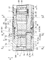
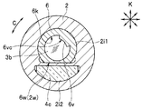
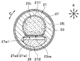
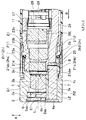
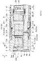
- FIGS. 2 is a partial cross-sectional view taken along the line II-II in FIG. 1 in a state where the adapter is attached to the distal end of the insertion part in FIG. 1, and FIG. 3 is a view of the adapter taken along the line III-III in FIG. 4 is a cross-sectional view of the tip portion and the adapter along the line IV-IV in FIG. 2, and FIG. 5 is a view showing a cross section of the tip portion along the line VV in FIG.
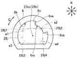
- FIG. 6 is an enlarged plan view showing the type discrimination diaphragm of FIG. 2 together with the image sensor.
- FIG. 7 is a plan view showing the type discrimination diaphragm of FIG. 6 in the circumferential direction of the adapter with respect to the lens frame of the adapter.
- FIG. 8 is a plan view showing the state of being rotated and attached together with the image sensor, FIG. 8 is a diagram showing a state in which the image forming portion of the type determining diaphragm is displayed on the monitor of FIG. 1, and FIG. It is a figure explaining the angle prescription
- the tip portion 11 includes a tip portion main body 21 formed in a substantially columnar shape.
- a male thread is formed on the outer peripheral surface of the tip body 21 to which a retaining ring 8 (to be described later) of the adapter 1 is screwed when the adapter 1 is mounted on the tip 11.
- a convex portion 21 d that protrudes forward from the distal end surface 21 s is formed on the distal end surface 21 s of the distal end portion main body 21.
- the convex portion 21 d is fitted into the fitting portion 2 h 1 in the concave portion 2 h formed on the base end surface 2 b of the lens frame 2, which will be described later, of the adapter 1.
- 11 is a member for positioning the adapter 1 in the circumferential direction C with respect to 11.
- the convex portion 21d does not have a circular shape when viewed in plan from the optical axis L, and has a shape in which a D-cut 21dw is formed on a part of the outer periphery. Yes. Further, the D-cut 21dw prevents the adapter 1 from rotating in the circumferential direction C with respect to the distal end portion 11 when the convex portion 21d is fitted into the fitting portion 2h1. That is, the adapter 1 is positioned in the circumferential direction C with respect to the distal end portion 11.
- a groove 21 dm into which a later-described pin 2 p of the adapter 1 is fitted when a part of the outer peripheral surface of the convex portion 21 d is attached to the distal end portion 11 is formed.
- the adapter 1 is prevented from rotating in the circumferential direction C with respect to the tip portion 11 when the convex portion 21d is fitted into the fitting portion 2h1. It is peeling. That is, the adapter 1 is positioned in the circumferential direction C with respect to the distal end portion 11 by fitting the pin 2p into the groove 21dm.
- a lens unit 23 including a plurality of lenses 23a, 23b, and 23c, and a CCD and C-MOS for observing the inside of the subject and imaging the inside of the subject in the distal end portion 11.
- An imaging element 28 such as the above and an imaging substrate 29 are provided. Note that the number of lenses constituting the lens unit 23 is not limited to three.
- a through hole 21i1 that penetrates the distal end portion main body 21 and the convex portion 21d in the insertion direction S is formed in the distal end portion main body 21 and the convex portion 21d, and the lens 23a and the lens are formed in the through hole 21i1. 23b is fixed.
- the lens 23a is fixed so as to be exposed to the tip surface 21ds of the convex portion 21d, and the lens 23b is located behind the lens 23a in the insertion direction S (hereinafter, simply referred to as the rear). It is fixed.
- a D-cut 23aw parallel to the D-cut 21dw is formed at a position facing the D-cut 21dw of the convex portion 21d on a part of the outer periphery of the lens 23a. That is, the lens 23a does not have a circular shape when viewed in plan from the optical axis L, but has a shape partially cut away by the D-cut 23aw.
- the distal end side of the image sensor fixing frame 27 having the lens 23c fixed therein is fixed to the inner periphery behind the position where the lens 23b of the through hole 21i1 is fixed, and the base end surface of the lens 23c is fixed.
- the light receiving section 28j having an outer shape of the imaging element 28 having a rectangular shape, specifically, a rectangular shape is fixed to the imaging position of the lens unit 23 with high accuracy.
- a D-cut 23cw is also formed on a part of the outer periphery of the lens 23c as shown in FIG.
- the positioning of the lens 23c in the circumferential direction C with respect to the light receiving unit 28j is performed by the operator under observation with a microscope, as shown in FIG. 5, with the D cut 23cw and the light receiving unit 28j or the outer shape of the lens 23c from the light receiving unit 28j.
- the lens 23c By attaching the lens 23c to the light receiving portion 28j so that the long side of the outline of the effective pixel region 30 is smaller and parallel to each other and the D-cut 23cw is perpendicular to the short side of the outline. Done.
- the center 28c of the light receiving portion 28j coincides with the optical center 23cc of the lens 23c.
- the positioning of the lens 23c in the circumferential direction C with respect to the image sensor fixing frame 27 is such that the D cut 23cw matches the D cut 27w1 formed on a part of the inner periphery of the image sensor fixing frame 27 as shown in FIG. This is done by fixing the lens 23 c in the image sensor fixing frame 27.
- the positioning in the circumferential direction C of the image sensor fixing frame 27 with respect to the distal end main body 21 is performed on the D cut 21w formed by the through hole 21i1 to the D cut 27w2 on the outer periphery of the image sensor fixing frame 27. Is performed by fixing the distal end side of the image sensor fixing frame 27 to the distal end portion main body 21 so as to match.
- an image pickup substrate 29 is electrically connected to the image pickup element 28, and a signal line (not shown) extends backward from the image pickup substrate 29.
- the signal line is inserted into the insertion unit 10, the operation unit 15, and the universal cord 17, and the extension end is connected to an image processing unit (not shown) in the apparatus main body 50.
- the distal end main body 21 is provided with a universal cord 17, an operation portion 15, a distal end side of a light guide 26 inserted into the insertion portion 10, and a cover glass 25.
- a through hole 21i2 that penetrates the distal end body 21 in the insertion direction S is formed in the distal end body 21, and the distal end side of the light guide 26 and the cover glass 25 are formed in the through hole 21i2. It is fixed.
- the front end of the light guide 26 is abutted against the base end surface of the cover glass 25, and the front side surface of the cover glass 25 (hereinafter referred to as the front end surface) is exposed to the front end surface 21s. It is fixed.
- the light guide 26 guides illumination light emitted from a light source (not shown) provided in the apparatus main body 50 to the distal end of the insertion portion 10, that is, the cover glass 25.
- the adapter 1 includes a lens frame 2 formed in a substantially cylindrical shape.
- a retaining ring 8 having an internal thread formed on the inner peripheral surface is provided on the outer periphery on the proximal end side of the lens frame 2.
- the female screw of the retaining ring 8 is screwed into the male screw of the distal end portion main body 21 while rotating in one direction, so that the adapter 1 is fixed to the distal end portion 11. The Therefore, when the adapter 1 is rotated in the other direction, the screwing of the female screw with respect to the male screw is released, and the adapter 1 is detached from the distal end portion 11.
- the lens frame 2 is formed with through holes 2 i 1 and 2 i 2 that penetrate the lens frame 2 along the insertion direction S.
- a concave portion 2h is formed on the base end surface 2b of the lens frame 2 so as to be recessed forward from the base end surface 2b along the insertion direction S.
- the recessed portion 2h is formed with a fitting portion 2h2 into which the distal end side of the distal end portion main body 21 is fitted when the adapter 1 is mounted on the distal end portion 11, and recessed forward of the fitting portion 2h2. It is comprised by the fitting part 2h1 by which the convex part 21d is fitted.
- the fitting part 2h1 communicates with the through hole 2i1, and the fitting part 2h2 communicates with the through hole 2i2.
- the distal end surface 21 ds of the convex portion 21 d comes into contact with the bottom surface 2 ha of the fitting portion 2 h 1, and the bottom surface 2 hb of the fitting portion 2 h 2 contacts the bottom surface 2 hb of the distal end portion main body 21.
- the tip surface 21s faces each other.
- a pin 2p protruding inward in the radial direction K toward the fitting portion 2h1 is formed at a part of the portion where the fitting portion 2h1 is formed, as shown in FIG. Is provided.
- the pin 2p is fitted into a groove 21dm formed on the outer peripheral surface of the tip end body 21 after the female screw of the adapter 1 is screwed into the male screw of the tip end body 21.
- the lens unit 3 for observing the inside of the subject composed of the lenses 3a, 3b, and 3c, which are a plurality of optical members, specifically the front of the adapter 1, and the lens 3a are the adapter. It is being fixed so that it may be exposed to the front end surface of 1. Note that the number of lenses constituting the lens unit 3 is not limited to three.
- the adapter 1 when the adapter 1 is attached to the distal end portion 11, the observation site in the subject is imaged on the light receiving portion 28 j of the image sensor 28 via the lens unit 3 and the lens unit 23.
- the rod lens 4c that is elongated along the insertion direction S
- the ball lens 4b that contacts the tip surface of the rod lens 4c
- the tip of the ball lens 4b and the tip of the adapter 1 are inserted into the through hole 2i2.
- An illumination optical system 4 composed of a cover glass 4a exposed on the surface is fixed.
- the illumination optical system 4 receives illumination light irradiated from the tip of the cover glass 25 when the adapter 1 is attached to the tip portion 11 and supplies illumination light to the subject. Specifically, the rod lens 4c guides the illumination light emitted from the cover glass 25 to the ball lens 4b, and the ball lens 4b diffuses the illumination light into the subject.
- the cover glass 4a protects the ball lens 4b.
- a brightness adjusting diaphragm (hereinafter simply referred to as a diaphragm) 7 for adjusting the observation depth is fixed to the front end surface of the lens 3c in the through hole 2i1.
- the diaphragm 7 has an opening 7k opened on the optical axis L of the lens unit 3. Further, the position where the diaphragm 7 is fixed is not limited to the front end surface of the lens 3c, and may be fixed at any position with respect to the through hole 2i1.
- the light is positioned so as to be sandwiched between the lens 3 b and the diaphragm 7 along the optical axis L at a position farther along the optical axis L than the diaphragm 7, specifically on the optical axis L.
- the type of adapter 1 is located at a position spaced forward along the axis L from the diaphragm 7 on the subject side, more specifically at a position abutting the proximal end surface 3ab of the lens 3a spaced forward L1 from the diaphragm 7.
- a discrimination diaphragm (hereinafter simply referred to as a diaphragm) 6 is fixed.
- the position at which the diaphragm 6 is fixed is not limited to the position in contact with the base end surface 3ab of the lens 3a, and is separated from the diaphragm 7 along the optical axis L so as to sandwich at least one lens. As long as it is a position, it may be anywhere in the through hole 2 i 1, and may be provided behind the diaphragm 7.
- the diaphragm 6 is formed, for example, by etching a copper foil so as to have an opening 6k opened on the optical axis L.
- the diaphragm 6 does not have a circular shape when viewed in plan along the optical axis L, and is formed in a shape in which a D-cut 6w is formed on a part of the outer periphery. ing.
- the aperture 6 is positioned in the circumferential direction C with respect to the lens frame 2 so that the aperture 6 is located in the through hole 2i1 so that the D cut 2w matches the D cut 2w formed by the through hole 2i1. This is done by being fixed.
- the positioning of the diaphragm 6 in the circumferential direction C with respect to the light receiving portion 28j when the adapter 1 is mounted on the tip end portion 11 is performed by aligning the D cut 2w and the D cut 6w as described above.
- Positioning in the circumferential direction C with respect to the lens frame 2 positioning in the circumferential direction C of the image sensor fixing frame 27 with respect to the distal end body 21 by matching the D cut 21w and the D cut 27w2, and a D cut 27w1 and a D cut 23cw Of the lens 23c with respect to the image sensor fixing frame 27 by matching, and the circumference of the lens 23c with respect to the light receiving unit 28j by matching the D cut 23cw with the outline of the light receiving unit 28j or the effective pixel region 30.
- Positioning of the adapter 1 relative to the tip 11 by positioning in the direction C and inserting the pin 2p into the groove 21dm It is defined by five positioning by the C positioning.
- the diaphragm 6 narrows down the light imaged on the light receiving part 28j of the image sensor 28 via the lens unit 3 when the adapter 1 is attached to the tip part 11.
- a flare that removes unnecessary light, specifically, light from outside the field of view or light from outside the field of view reflected by the lens frame 2 or the like is incident on the light receiving unit 28j and flare is prevented. It functions as an aperture.
- the focus adjustment with respect to the light receiving unit 28j is performed by adjusting the thickness and the number of the diaphragms 6.
- the diaphragm 6 has an image forming portion 6v that forms an image on the light receiving portion 28j by projecting into the opening 6k.
- the diaphragm 6 is provided along the optical axis L by being separated from the diaphragm 7 by L1. This is because when 6v is imaged on the light receiving unit 28j, an image is formed with the outline of the image forming unit 6v blurred, and it becomes difficult for the CPU 53 to determine the image forming unit 6v described later.
- the diaphragm 7 is a diaphragm for adjusting brightness, and the distance from the diaphragm 7 to the diaphragm 6 is increased along the optical axis L, and the luminous flux passing through the aperture 6k becomes thinner. This is because the outline of the imaging unit 6v provided in the diaphragm 6 is easily imaged clearly on the light receiving unit 28j.
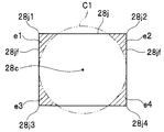
- the imaging unit 6v has an outer center of the diaphragm 6 and a center 28c of the light receiving unit 28j (optical center 23cc of the lens 23c) with respect to the diaphragm 6.
- a case where the light receiving portion 28j is formed at a position overlapping the corner region e2 including the corner portion 28j2, that is, a position where the image is formed in the region e2, is shown as an example.
- the imaging unit 6v is located at a position overlapping the corner region e1 including the corner portion 28j1 of the light receiving unit 28j, that is, a position where the imaging is performed on the region e1, and a position overlapping the corner region e2 with respect to the stop 6. That is, a position where an image is formed in the area e2, a position overlapping the area e3 of the corner including the corner 28j3 of the light receiving part 28j, that is, a position where the image is formed in the area e3, and a corner including the corner 28j4 of the light receiving part 28j. It is only necessary to be provided at at least one of a position overlapping the area e4, that is, a position where the image is formed on the area e4.
- the CPU 53 provided in the apparatus main body 50 detects the position and the number of the image forming unit 6v formed on the light receiving unit 28j by performing image processing, so that the adapter 1 mounted on the distal end unit 11 is detected.
- the function of discriminating the type of data and displaying the discrimination result on the monitor 55 is provided. At this time, as described above, if the imaging unit 6v is clearly imaged on the light receiving unit 28j, the CPU 53 does not erroneously detect the position and number of the imaging unit 6v.
- the CPU 53 determines that the adapter is not attached to the distal end portion 11 without determining the type of the adapter 1 when the imaging portion 6v is not in the imaging state in all the four corner areas e1 to e4. This is displayed on the monitor 55.
- the CPU 53 does not determine the type of the adapter 1 when the image forming unit 6v is formed on all the four corner areas e1 to e4. This is because if the imaging unit 6v is imaged in all of the regions e1 to e4, the amount of light incident on the light receiving unit 28j is insufficient, so that the image is formed in all of the regions e1 to e4. This is because the CPU 53 tends to misrecognize when the portion 6v is imaged and when the inside of the subject is dark.
- the CPU 53 can determine 14 types of adapters 1 attached to the distal end portion 11 by subtracting the above-described two types from 16 types.
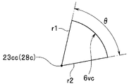
- the imaging unit 6v has a partial arc-shaped part 6vc having the center 28c of the light receiving part 28j as the center of the circle. That is, the center of the part 6vc coincides with the centers 28c and 23cc.
- the length of the arc shape in the circumferential direction C of the part 6vc is such that the end portions 6va and 6vb in the circumferential direction C of the imaging portion 6v and the center 28c of the light receiving portion 28j. It is defined by the angle ⁇ formed by the lines r1 and r2 when connected by the lines r1 and r2.
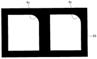
- the imaging part 6v has the partial arc-shaped part 6vc, when the imaging part 6v is provided at a position where an image is formed in the region e2, as shown in FIG. As shown in FIG. 8, the portion 6 v is displayed with an arc shape on the upper right side of the monitor 55.
- the imaging unit 6v when the imaging unit 6v is provided at a position where the image is formed in the region e1, the imaging unit 6v is displayed with an arc shape on the upper left side of the monitor 55, and the imaging unit 6v is displayed in the region e3.
- the image forming unit 6v is displayed with an arc shape on the lower left side of the monitor 55, and the image forming unit 6v is provided at the position where the image is formed in the region e4.
- the image forming unit 6v is displayed with an arc shape on the lower right side of the monitor 55.
- the operator can easily recognize the type of the adapter 1 from the position and number of the imaging unit 6v displayed on the monitor 55. Even if the imaging unit 6v is not displayed on the monitor 55, the determination result of the CPU 53 is displayed on the monitor 55, so that the operator can easily visually recognize the type of the adapter 1.
- the imaging portion 6v has a partial arc-shaped portion 6vc even if the diaphragm 6 is displaced and fixed in the circumferential direction C with respect to the through hole 2i1 as shown in FIG. That is, even if the diaphragm 6 is displaced and fixed in the circumferential direction C with respect to the light receiving section 28j, the center 28c of the light receiving section 28j and the outer shape center of the diaphragm 6 coincide with each other. This is because when the region 6vc is provided, the shape of the image forming unit 6v formed on the light receiving unit 28j is the same.
- the angle ⁇ of the portion 6vc shown in FIG. 9 is determined by the positioning error in the circumferential direction C with respect to the lens frame 2 of the diaphragm 6 defined in the positioning in the circumferential direction C of the diaphragm 6 with respect to the light receiving portion 28j.
- the positioning error in the circumferential direction C of the imaging device fixing frame 27 with respect to the image sensor, the positioning error in the circumferential direction C of the lens 23c with respect to the imaging device fixing frame 27, and the positioning error in the circumferential direction C of the lens 23c with respect to the light receiving portion 28j It must be set larger than the value obtained by adding the positioning error in the circumferential direction C of the adapter 1 with respect to the distal end portion 11.
- the imaging unit 6v is connected to the light receiving unit 28j after the diaphragm 6 is assembled due to the positioning error in the circumferential direction C. This is because the image is lost.
- the four corner regions e1 to e4 of the light receiving unit 28j described above are optically large in aberration and distortion, have poor imaging performance, and the illuminance of the reflected light of the illumination light also radiates from the center of the reflected light. Since it becomes a dark part because it becomes smaller, the image quality often deteriorates and is not used for observation of a normal subject.
- the degraded image quality areas e1 to e4 are not used for observation of the subject but are used as the imaging area of the imaging unit 6v for determining the type of the adapter 1. Therefore, even if the imaging unit 6v is imaged on the light receiving unit 28j, the observation of the subject is not affected, and the type of the adapter 1 can be determined.
- FIG. 10 is a diagram for explaining the four corner regions where the imaging portion of the adapter is imaged in the light receiving portion of the image pickup device in FIG. 2
- FIG. 11 is a diagram illustrating the connection of the adapter in the light receiving portion of the image pickup device in FIG. It is a figure explaining the area
- regions e1 to e4 at the four corners include an inscribed circle C1 with respect to the short side 28jf of the light receiving portion 28j having the center 28c of the light receiving portion 28j and a rectangular outer shape, and light reception. Between the four corners 28j1 to 28j4 of the portion 28j, four areas are set as shown by the oblique lines in FIG.
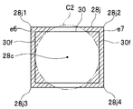
- the four corner areas e1 to e4 are short of the use pixel area 30 having the center 28c of the light receiving portion 28j as the center of the circle and the outer shape being smaller than the light receiving portion 28j and having a rectangular shape.
- the inscribed circle C2 with respect to the side 30f and the four corners 28j1 to 28j4 of the light receiving unit 28j it may be set within a region (e6, e7) where two can be formed as shown by hatching in FIG. Absent.
- the image of the image forming unit 6v formed outside the use pixel region 30 in the light receiving unit 28j is not displayed on the monitor 55, but the image processing of the image forming unit 6v by the CPU 53 is not affected. For this reason, even in this case, the CPU 53 can reliably determine the imaging unit 6v.
- the number of pixels is increased by reducing the pixel pitch of the light receiving unit.
- the observation depth becomes shallow as the pixel pitch decreases. Therefore, in order to increase the observation depth, there is a configuration in which the entire region of the light receiving unit 28j is not used. In such a configuration, the setting method of the regions e6 and e7 shown in FIG. 11 is preferable.
- the CPU 53 determines the positions and number of images formed in the four corner areas e1 to e4 of the light receiving unit 28j of the imaging unit 6v in the diaphragm 6 provided in the adapter 1. This indicates that the type of the adapter 1 attached to the distal end portion 11 is determined.
- a diaphragm 6 having an imaging portion 6v in the adapter 1 is provided separated by L1 so that the lens 3b is sandwiched between the diaphragm 7 for brightness adjustment and the diaphragm 7 along the optical axis L. Indicated.
- the CPU 53 incorrectly sets the position and number of the imaging unit 6v after image processing. Since it is not recognized, the recognition ability of the image forming unit 6v by the CPU 53 can be improved.
- the imaging unit 6v is shown to have a partial arc-shaped part 6vc with the center 28c of the light receiving unit 28j as the center of the circle.
- the angle ⁇ of the part 6vc is determined by the positioning error in the circumferential direction C of the diaphragm 6 with respect to the lens frame 2 defined in the positioning of the diaphragm 6 in the circumferential direction C with respect to the light receiving unit 28j, and the imaging element fixing frame with respect to the tip body 21. 27, the positioning error in the circumferential direction C of the lens 23c with respect to the image sensor fixing frame 27, the positioning error in the circumferential direction C of the lens 23c with respect to the light receiving portion 28j, and the adapter for the distal end portion 11. It was shown that it was set larger than the value obtained by adding 1 positioning error in the circumferential direction C.
- the endoscope 200 having a configuration capable of accurately and easily detecting the type of the adapter 1 from the diaphragm 6 imaged on the light receiving unit 28j.
- FIG. 12 is a partial cross-sectional view showing a modification in which an aperture for classification determination is sandwiched between a cover glass and a distal end surface of an objective lens of a lens unit provided in the adapter of FIG.
- the diaphragm 6 is fixed so as to come into contact with the base end surface 3ab of the objective lens 3a in the through hole 2i1.
- the diaphragm 6 may be fixed to the through hole 2i1 so as to contact the tip surface 3as of the objective lens 3a. Further, in such a configuration, if the diaphragm 6 is exposed at the tip end surface of the adapter, dust or oil may adhere to the diaphragm 6, so the diaphragm 6 can be attached to the objective lens 3 a. It is preferable to be sandwiched and fixed between the front end surface 3as and the cover glass 61 that prevents dirt or the like from adhering to the diaphragm 6. That is, the cover glass 61 is exposed on the tip surface of the adapter 1.
- the diaphragm 6 is fixed so as to come into contact with the distal end surface 3as, and therefore, compared with the case where it is fixed so as to come into contact with the proximal end surface 3ab as in the present embodiment described above. Since the distance L2 from the diaphragm 7 on the axis L becomes long (L2> L1), the image forming section 6v of the diaphragm 6 is imaged more clearly in the four corner areas e1 to e4 of the light receiving section 28j. For this reason, the discrimination of the imaging unit 6v by the CPU 53 can be improved as compared with the present embodiment described above. Other configurations and effects are the same as those of the present embodiment described above.
- FIG. 13 is a partial cross-sectional view showing a modified example in which a type determining diaphragm is provided separately from the flare diaphragm on the tip surface of the objective lens of the lens unit provided in the adapter of FIG.
- the type discriminating aperture 6 functions as a flare aperture that removes unnecessary light when the adapter 1 is attached to the distal end portion 11.
- the base end surface 3 ab of the objective lens 3 a has an opening 60 k that opens to the optical axis L, and narrows the light focused on the light receiving unit 28 j through the lens unit 3.
- a flare stop 60 for removing unnecessary light is fixed separately from the type determining stop 6, and the type determining stop 6 is fixed separately from the flare stop 60 on the tip surface 3 as of the objective lens 3 a. It does not matter.
- the diaphragm 6 may be integrally formed with the tip surface 3as by vapor deposition.
- the diaphragm 6 can be formed thinner along the optical axis L than the above-described embodiment, and even if the cover glass 61 is not provided, it is difficult for dust to collect in the diaphragm 6 and the oil stains. Since it becomes difficult, manufacturing cost can be reduced rather than the structure shown in FIG. Other configurations and effects are the same as those of the present embodiment described above.
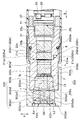
- FIG. 14 is a partial cross-sectional view in a state where an adapter is attached to the distal end portion of the insertion portion of the endoscope according to the present embodiment.
- the configuration of the endoscope according to the second embodiment has a known adapter that can be attached to and detached from the distal end portion of the insertion portion as compared with the endoscope according to the first embodiment shown in FIGS. 1 to 11 described above.
- the difference is that it is a side view adapter. Therefore, only this difference will be described, the same reference numerals are given to the same components as those in the first embodiment, and the description thereof will be omitted.
- the two or more types of adapters 1 that are detachable from the distal end portion 11 will be described by taking a side view adapter as an example. In the present embodiment, it is assumed that two or more types of direct-view adapters having different diameters and viewing angles are detachable from the distal end portion 11.
- the adapter 1 used in the present embodiment includes a lens frame 202 formed in a substantially cylindrical shape.
- a retaining ring 8 having an internal thread formed on the inner peripheral surface is provided.
- a concave portion 202 h is formed on the base end surface 202 b of the lens frame 202 so as to be recessed forward from the base end surface 202 b along the insertion direction S.
- the recessed portion 202h is formed to be recessed forward from the fitting portion 202h2 to which the tip side of the tip portion main body 21 is fitted when the adapter 1 is attached to the tip portion 11, and the fitting portion 202h2. It is comprised by the fitting part 202h1 by which the convex part 21d is fitted.
- the distal end surface 21 ds of the convex portion 21 d comes into contact with the bottom surface 202 ha of the fitting portion 202 h 1, and the bottom surface 202 hb of the fitting portion 202 h 2 contacts the bottom surface 202 hb.
- the tip surface 21s faces each other.
- a part of the part where the fitting part 202h1 is formed is arranged in the radial direction K toward the fitting part 202h1, as shown in FIG. 4 of the first embodiment described above.
- a pin (not shown) protruding inside is provided. The pin is inserted into a groove 21 dm (see FIG. 4) formed on the outer peripheral surface of the tip end body 21 after the female screw of the adapter 1 is screwed into the male screw of the tip end body 21.
- the lens frame 202 is formed with an L-shaped through hole 202i1 having one end opened on one side surface of the outer peripheral surface of the adapter 1 and the other end opened in the fitting portion 202h1.
- the observation unit is composed of a plurality of optical members such as a lens 203a, a prism 203b, a lens 203c, and a lens 203d and is located in the subject, specifically, on the radial direction K side with respect to the adapter 1.
- the lens unit 203 for observing the part is fixed so that the lens 203 a is exposed on one side surface of the outer peripheral surface of the adapter 1. Note that the number of lenses constituting the lens unit 203 is not limited to three.
- the adapter 1 when the adapter 1 is attached to the distal end portion 11, the observation site in the subject is imaged on the light receiving portion 28 j of the image sensor 28 via the lens unit 203 and the lens unit 23.
- the lens frame 202 is formed with a through hole 202i2 that penetrates in the insertion direction S.
- a cover member 205 is covered on the outer periphery of the lens frame 202 on the front end side. One end of the cover member 205 is opened on one side surface formed on the outer peripheral surface of the cover member 205 at the same position as the one side surface where the lens 203a of the lens frame 202 is exposed, and the other end is opened in the through hole 202i2.
- a letter-shaped through-hole 205i is formed.
- the through-holes 205i, 202i2 are illumination optics composed of a light guide 204b and a cover glass 204a that is in contact with the tip surface of the light guide 204b and exposed on one side surface of the cover member 205 described above.
- System 204 is fixed.
- the illumination optical system 204 has a function of supplying illumination light to the subject located on the radial direction K side with respect to the adapter 1.
- the diaphragm 7 is fixed to the tip surface of the lens 203d.
- the position where the diaphragm 7 is fixed is not limited to the front end surface of the lens 203d, and may be fixed at any position with respect to the through hole 202i1.
- the shape and function of the diaphragm 7 are the same as those of the diaphragm 7 of the first embodiment described above.
- the lens 203 c and the prism 203 b are disposed between the stop 7 and the position along the optical axis L at a position farther from the stop 7 along the optical axis L.
- the diaphragm 6 is fixed at a position spaced from the diaphragm 7 along the optical axis L so as to sandwich, more specifically at a position where the diaphragm 203 abuts the base end surface 203ab of the lens 203a separated from the diaphragm 7 along the optical axis L by L5.
- L5 has been.
- the position at which the diaphragm 6 is fixed is not limited to the position in contact with the base end surface 203ab of the lens 203a, but is separated from the diaphragm 7 along the optical axis L so as to sandwich at least one lens. It may be anywhere in the through hole 202i1 as long as it is a position.
- the positioning method, shape, and function of the diaphragm 6 in the circumferential direction C are the same as those of the diaphragm 6 of the first embodiment described above.
- the diaphragm 6 is only L5 so that the prism 203b and the lens 203c are sandwiched between the diaphragm 7 for brightness adjustment and the diaphragm 7 along the optical axis L. It was shown to be fixed apart.
- the diaphragm 6 is located at a distance L5 from the diaphragm 7 along the optical axis L.
- the CPU 53 does not erroneously recognize the position and number of the imaging unit 6v.
- Other effects are the same as those of the first embodiment described above.
- FIG. 15 is a partial cross-sectional view in a state where an adapter is attached to the distal end portion of the insertion portion of the endoscope according to the present embodiment
- FIG. 16 shows each lens of a direct-view adapter for stereo measurement on the monitor of FIG.
- FIG. 6 is a diagram illustrating a state in which an imaging portion of a type determining diaphragm is displayed.
- the configuration of the endoscope of the third embodiment has an adapter that is detachable at the distal end of the insertion portion.
- the difference is that it is a known direct-view adapter for stereo measurement. Therefore, only this difference will be described, the same reference numerals are given to the same components as those in the first embodiment, and the description thereof will be omitted.
- the two or more types of adapters 1 that are detachably attached to the distal end portion 11 will be described using a direct-view adapter for stereo measurement as an example. Further, in the present embodiment, it is assumed that two or more types of direct-viewing adapters for stereo measurement having different diameters and viewing angles are detachable from the distal end portion 11.
- the adapter 1 includes a lens frame 302 formed in a substantially cylindrical shape.
- the lens frame 302 includes a first lens frame 302a and a second lens frame 302b, and a distal end of the second lens frame 302b is formed in a recess 302ah formed on a base end surface of the first lens frame 302a.
- the first lens frame 302a and the second lens frame 302b are connected by fitting the sides.
- a retaining ring 8 having an internal thread formed on the inner peripheral surface is provided.
- the second lens frame 302b is formed with a through-hole 302bi that penetrates the second lens frame 302b along the insertion direction S.
- a concave portion 302h is formed on the base end surface 302bb of the second lens frame 302b so as to be recessed forward from the base end surface 302bb along the insertion direction S.
- the recessed portion 302h is formed with a fitting portion 302h2 into which the distal end side of the distal end portion main body 21 is fitted when the adapter 1 is attached to the distal end portion 11, and a recess recessed forward of the fitting portion 302h2. It is comprised by the fitting part 302h1 by which the convex part 21d is fitted.
- the fitting portion 302h1 communicates with the through hole 302bi.
- the tip surface 21ds of the convex portion 21d comes into contact with the bottom surface 302ha of the fitting portion 302h1, and the bottom surface 302hb of the fitting portion 302h2 touches the bottom surface 302hb.
- the tip surface 21s faces each other.
- a protruding pin (not shown) is provided on the proximal end side of the second lens frame 302b. The pin is fitted into a groove 21 dm formed on the outer peripheral surface of the tip end body 21 after the female screw of the adapter 1 is screwed into the male screw of the tip end body 21.
- lenses 303b, 303c, and 303d which are a plurality of optical members, are fixed in the through hole 302bi.
- the first lens frame 302a is formed with two through holes 302ai1 and 302ai2 penetrating in parallel along the insertion direction S, and each through hole 302ai1 and 302ai2 is formed on the front end surface of the first lens frame 302a.
- the recessed portion 302ah is opened.
- a cover glass 361 is fitted in the recess 302ah.
- a plurality of lenses 303a1 that are optical members are fixed to the through hole 302ai1
- a plurality of lenses 303a2 that are optical members are fixed to the through hole 302ai2.
- the lens 303a1 and the lens 303a2 have parallax.
- the cover glass 361 and the lenses 303 a 1, 303 a 2, 303 b, 303 c, and 303 d constitute a lens unit 303 that observes the inside of the subject, specifically, the front of the adapter 1.
- the number of lenses constituting the lens unit 303 is not limited to the number described above.
- the observation site in the subject is, on the other hand, the light receiving portion of the image sensor 28 via the cover glass 361, the lenses 303 a 1, 303 b, 303 c, 303 d, and the lens unit 23. 28j, and on the other hand, it has a parallax with the image that has passed through the lens 303a1 through the cover glass 361, the lenses 303a2, 303b, 303c, and 303d, and the lens unit 23. Imaged.
- the diaphragm 7 is fixed between the lens 303c and the lens 303b.
- the position where the diaphragm 7 is fixed may be any position with respect to the through hole 302bi.
- the shape and function of the diaphragm 7 are the same as those of the diaphragm 7 of the first embodiment described above.
- the positions of the lenses 303a1 and 303b between the stop 7 and the position along the optical axis L are more distant from the stop 7 along the optical axis L.
- a position spaced forward from the diaphragm 7 toward the subject side along the optical axis L more specifically at a position contacting the distal end surface 303a1s of the lens 303a1 separated from the diaphragm 7 by L6 forward.
- the diaphragm 6 ⁇ is fixed.
- a position spaced forward from the diaphragm 7 on the subject side along the optical axis L more specifically, at a position abutting on the front end surface 303a2s of the lens 303a2 separated from the diaphragm 7 by L6 forward.
- the diaphragm 6 ⁇ is fixed.
- the positions at which the diaphragms 6 ⁇ and 6 ⁇ are fixed are not limited to the positions in contact with the front end surfaces 302a1s and 302a2s of the lenses 302a1 and 302a2, and at least the lens is disposed between the diaphragm 7 and the diaphragm 7 along the optical axis L. It may be anywhere in the through holes 302ai1 and 302ai2 as long as they are spaced apart so as to sandwich one sheet, and may be fixed behind the diaphragm 7.
- the diaphragms 6 ⁇ and 6 ⁇ may be fixed integrally.
- the imaging unit 6v may be provided in either one of the diaphragms 6 ⁇ and 6 ⁇ .
- the imaging units 6v may be provided at different positions for the diaphragms 6 ⁇ and 6 ⁇ . The effect is that the number of adapters that can be identified increases.
- the positioning method, shape and function of the diaphragms 6 ⁇ and 6 ⁇ in the circumferential direction C are the same as those of the diaphragm 6 of the first embodiment described above.
- the diaphragm 6 ⁇ in the adapter 1 is separated by L6 so that the lenses 303b and 303a1 are sandwiched between the diaphragm 7 for brightness adjustment and the diaphragm 7 along the optical axis L. And showed that it is fixed.
- the diaphragm 6 ⁇ is fixed to be separated by L6 so that the lenses 303b and 303a2 are sandwiched between the diaphragm 7 for brightness adjustment and the diaphragm 7 along the optical axis L.
- the diaphragms 6 ⁇ and 6 ⁇ are located at a distance L6 from the diaphragm 7 along the optical axis L.
- the outline of the imaging unit 6v is as shown in FIG. Since the image is clearly formed, the CPU 53 does not erroneously recognize the position and number of the image forming unit 6v.
- Other effects are the same as those of the first embodiment described above.
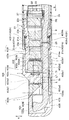
- FIG. 17 is a partial cross-sectional view in a state where an adapter is attached to the distal end portion of the insertion portion of the endoscope according to the present embodiment.
- the configuration of the endoscope of the fourth embodiment is a stereo measurement in which an adapter that is detachable at the distal end of the insertion portion is known.
- the difference is that it is a side view adapter for use. Therefore, only this difference will be described, the same reference numerals are given to the same components as those in the second embodiment, and the description thereof will be omitted.
- the two or more types of adapters 1 that are detachably attached to the distal end portion 11 will be described by taking a side-view adapter for stereo measurement as an example.
- a side-view adapter for stereo measurement it is assumed that two or more types of stereo measurement side-view adapters having different diameters and viewing angles are detachable from the distal end portion 11.
- the adapter 1 used in the present embodiment includes a lens frame 402 formed in a substantially cylindrical shape.
- the lens frame 402 includes a first lens frame 402a and a second lens frame 402b, and a distal end of the second lens frame 402b is formed in a recess 402ah formed on a base end surface of the first lens frame 402a. By fitting the sides, the first lens frame 402a and the second lens frame 402b are connected.
- a retaining ring 8 having an internal thread formed on the inner peripheral surface is provided.
- a recess 402h is formed that is recessed forward from the base end surface 402bb along the insertion direction S.
- the recessed portion 402h is formed with a fitting portion 402h2 into which the distal end side of the distal end portion main body 21 is fitted when the adapter 1 is attached to the distal end portion 11, and recessed forward from the fitting portion 402h2. It is comprised by the fitting part 402h1 by which the convex part 21d is fitted.
- the distal end surface 21 ds of the convex portion 21 d comes into contact with the bottom surface 402 ha of the fitting portion 402 h 1, and the bottom surface 402 hb of the fitting portion 402 h 2 contacts the bottom surface 402 hb of the distal end portion main body 21.
- the tip surface 21s faces each other.
- a part of the portion where the fitting portion 402h1 is formed is directed toward the fitting portion 402h1 as shown in FIG. 4 of the first embodiment described above.
- a pin (not shown) protruding inward in the radial direction K is provided. The pin is inserted into a groove 21 dm (see FIG. 4) formed on the outer peripheral surface of the tip end body 21 after the female screw of the adapter 1 is screwed into the male screw of the tip end body 21.
- the second lens frame 402b is formed with a through hole 402bi1 penetrating in the insertion direction S.
- a plurality of lenses 403d, 403e, and 403f, which are optical members, are fixed in the through hole 402bi1.
- a through hole 402bi2 that penetrates in the insertion direction S is formed in the second lens frame 402b.
- the first lens frame 402a is formed with 402ai1 and 402ai2 penetrating along the insertion direction S.
- a plurality of optical members, lenses 403a1 and 403a2, a lens 403c, and a prism 403b are fixed in the through hole 402ai1.
- the lenses 403a1 and 403a2 are provided in parallel in the depth direction of FIG.
- the lens 403a1 and the lens 403a2 have parallax.
- the prism 403b is exposed on one side surface of the outer peripheral surface of the adapter 1.
- a cover member 405 is covered on the outer periphery of the first lens frame 402a on the front end side.
- the cover member 405 has an L-shape with one end opened on one side surface formed on the outer peripheral surface of the cover member 405 at the same position as one side surface where a prism 403b described later is exposed, and the other end opened in the through hole 402ai2.
- Through-holes 405i are formed.
- the through holes 405i, 402ai2, and 402bi2 include a light guide 404b and a cover glass 404a that is in contact with the distal end surface of the ride guide 404b and exposed on one side surface of the cover member 405 described above.
- the illumination optical system 404 is fixed.
- the illumination optical system 404 has a function of supplying illumination light to the subject located on the radial direction K side with respect to the adapter 1.
- the lenses 403a1 and 403a2, the prism 403b, and the lenses 403c, 403d, 403e, and 403f constitute a lens unit 403 that observes an observation site located in the subject, specifically, the radial direction K side with respect to the adapter 1. Has been.
- the number of lenses constituting the lens unit 403 is not limited to the number described above.
- the observation site in the subject is on the other hand, the prism 403b, the lens 403a1, the lenses 403c, 403d, 403e, and 403f to the light receiving portion 28j of the image sensor 28.
- the image is formed with parallax with the image passing through the lens 403a1 to the light receiving portion 28j of the image sensor 28 via the prism 403b, the lens 403a2, the lenses 403c, 403d, 403e, and 403f. .
- the aperture 7 is fixed between the lens 403d and the lens 403e in the through hole 402bi1.
- the position where the diaphragm 7 is fixed may be any position with respect to the through hole 402bi1.
- the shape and function of the diaphragm 7 are the same as those of the diaphragm 7 of the first embodiment described above.
- the lenses 403a1, 403a2, 403c, and 403d are arranged with the stop 7 along the optical axis L at positions away from the stop 7 along the optical axis L, specifically, on the optical axis L.
- the diaphragm 7 At a position spaced apart from the diaphragm 7 along the optical axis L so as to be sandwiched between them, more specifically, at a position where the diaphragm 7 abuts on the base end surface 403bb of the prism 403b separated by L7 along the optical axis L from the diaphragm 7. 6 is fixed.
- the position at which the diaphragm 6 is fixed is not limited to the position in contact with the base end surface 403bb of the prism 403b, and is separated from the diaphragm 7 along the optical axis L so as to sandwich at least one lens. It may be anywhere in the through hole 402ai1 as long as it is a position.
- the positioning method, shape, and function of the diaphragm 6 in the circumferential direction C are the same as those of the diaphragm 6 of the second embodiment described above.
- the aperture 6 sandwiches the lenses 403 a 1, 403 a 2, 403 c, and 403 d between the aperture 7 for brightness adjustment and the aperture 7 along the optical axis L. , L7 is shown to be spaced apart.
- the diaphragm 6 is located at a distance L7 from the diaphragm 7 along the optical axis L. Since the outline of the imaging unit 6v is clearly imaged in each of the regions e1 to e4 provided in the imaging regions of the image of the subject having two parallaxes imaged by the lenses 403a1 and 403a2, The CPU 53 does not misrecognize the position and number of the image forming unit 6v. Other effects are the same as those of the second embodiment described above.
- an industrial endoscope is shown as an example, but it goes without saying that it may be applied to a medical endoscope.
Landscapes
- Health & Medical Sciences (AREA)
- Life Sciences & Earth Sciences (AREA)
- Surgery (AREA)
- Physics & Mathematics (AREA)
- Engineering & Computer Science (AREA)
- Optics & Photonics (AREA)
- Medical Informatics (AREA)
- General Health & Medical Sciences (AREA)
- Pathology (AREA)
- Nuclear Medicine, Radiotherapy & Molecular Imaging (AREA)
- Biomedical Technology (AREA)
- Heart & Thoracic Surgery (AREA)
- Biophysics (AREA)
- Molecular Biology (AREA)
- Animal Behavior & Ethology (AREA)
- Radiology & Medical Imaging (AREA)
- Public Health (AREA)
- Veterinary Medicine (AREA)
- Multimedia (AREA)
- Astronomy & Astrophysics (AREA)
- General Physics & Mathematics (AREA)
- Manufacturing & Machinery (AREA)
- Instruments For Viewing The Inside Of Hollow Bodies (AREA)
- Endoscopes (AREA)
Abstract
L'endoscope d'après la présente invention comprend : un objectif (3) ; un diaphragme (7) ; un diaphragme (6) ; et un élément de capture d'image (28). Le diaphragme (6) comporte des unités d'imagerie (6v) imagées sur une unité de photorécepteur (28j). Dans chaque adaptateur d'une pluralité d'adaptateurs (1), les unités d'imagerie (6v) différent en position et en nombre d'unités montées sur le diaphragme (6). Le dispositif comprend en outre une UCT conçue pour déterminer le type d'adaptateur (1) en déterminant la position et le nombre des unités d'imagerie (6v) imagées sur l'unité de photorécepteur (28j).
Priority Applications (2)
| Application Number | Priority Date | Filing Date | Title |
|---|---|---|---|
| JP2015537571A JP6430948B2 (ja) | 2013-09-20 | 2014-05-16 | 内視鏡 |
| US15/073,056 US9999344B2 (en) | 2013-09-20 | 2016-03-17 | Endoscope |
Applications Claiming Priority (2)
| Application Number | Priority Date | Filing Date | Title |
|---|---|---|---|
| JP2013-195739 | 2013-09-20 | ||
| JP2013195739 | 2013-09-20 |
Related Child Applications (1)
| Application Number | Title | Priority Date | Filing Date |
|---|---|---|---|
| US15/073,056 Continuation US9999344B2 (en) | 2013-09-20 | 2016-03-17 | Endoscope |
Publications (1)
| Publication Number | Publication Date |
|---|---|
| WO2015040887A1 true WO2015040887A1 (fr) | 2015-03-26 |
Family
ID=52688550
Family Applications (1)
| Application Number | Title | Priority Date | Filing Date |
|---|---|---|---|
| PCT/JP2014/063106 Ceased WO2015040887A1 (fr) | 2013-09-20 | 2014-05-16 | Endoscope |
Country Status (3)
| Country | Link |
|---|---|
| US (1) | US9999344B2 (fr) |
| JP (1) | JP6430948B2 (fr) |
| WO (1) | WO2015040887A1 (fr) |
Cited By (2)
| Publication number | Priority date | Publication date | Assignee | Title |
|---|---|---|---|---|
| WO2018012121A1 (fr) * | 2016-07-12 | 2018-01-18 | オリンパス株式会社 | Outil d'assistance au montage/démontage d'un adaptateur optique d'endoscope et système d'endoscope |
| WO2023170788A1 (fr) * | 2022-03-08 | 2023-09-14 | アイリス株式会社 | Outil d'assistance, dispositif d'imagerie, programme et procédé |
Families Citing this family (3)
| Publication number | Priority date | Publication date | Assignee | Title |
|---|---|---|---|---|
| JP5889495B2 (ja) * | 2014-02-14 | 2016-03-22 | オリンパス株式会社 | 内視鏡システム |
| DE102017123896A1 (de) * | 2017-10-13 | 2019-04-18 | Olympus Winter & Ibe Gmbh | Optisches System für ein Stereo-Videoendoskop |
| US20230371813A1 (en) * | 2022-05-17 | 2023-11-23 | EyeQ Technologies, Inc. | Three-dimensional ocular endoscope device and methods of use |
Citations (6)
| Publication number | Priority date | Publication date | Assignee | Title |
|---|---|---|---|---|
| JPH02100013A (ja) * | 1988-10-07 | 1990-04-12 | Olympus Optical Co Ltd | 内視鏡用光学アダプタ |
| JPH11109257A (ja) * | 1997-10-03 | 1999-04-23 | Olympus Optical Co Ltd | 内視鏡撮像光学系 |
| JP2000292713A (ja) * | 1998-12-15 | 2000-10-20 | Olympus Optical Co Ltd | 内視鏡用光学アダプタ |
| JP2002191547A (ja) * | 2000-12-26 | 2002-07-09 | Olympus Optical Co Ltd | 内視鏡装置及び内視鏡装置の駆動方法 |
| JP2003005096A (ja) * | 2001-06-27 | 2003-01-08 | Olympus Optical Co Ltd | 内視鏡装置 |
| JP2004033487A (ja) * | 2002-07-03 | 2004-02-05 | Olympus Corp | 内視鏡装置 |
Family Cites Families (1)
| Publication number | Priority date | Publication date | Assignee | Title |
|---|---|---|---|---|
| US8314835B2 (en) * | 2009-01-23 | 2012-11-20 | Olympus Corporation | Endoscope adapter including light emitting diode, and adapter type endoscope |
-
2014
- 2014-05-16 JP JP2015537571A patent/JP6430948B2/ja active Active
- 2014-05-16 WO PCT/JP2014/063106 patent/WO2015040887A1/fr not_active Ceased
-
2016
- 2016-03-17 US US15/073,056 patent/US9999344B2/en active Active
Patent Citations (6)
| Publication number | Priority date | Publication date | Assignee | Title |
|---|---|---|---|---|
| JPH02100013A (ja) * | 1988-10-07 | 1990-04-12 | Olympus Optical Co Ltd | 内視鏡用光学アダプタ |
| JPH11109257A (ja) * | 1997-10-03 | 1999-04-23 | Olympus Optical Co Ltd | 内視鏡撮像光学系 |
| JP2000292713A (ja) * | 1998-12-15 | 2000-10-20 | Olympus Optical Co Ltd | 内視鏡用光学アダプタ |
| JP2002191547A (ja) * | 2000-12-26 | 2002-07-09 | Olympus Optical Co Ltd | 内視鏡装置及び内視鏡装置の駆動方法 |
| JP2003005096A (ja) * | 2001-06-27 | 2003-01-08 | Olympus Optical Co Ltd | 内視鏡装置 |
| JP2004033487A (ja) * | 2002-07-03 | 2004-02-05 | Olympus Corp | 内視鏡装置 |
Cited By (5)
| Publication number | Priority date | Publication date | Assignee | Title |
|---|---|---|---|---|
| WO2018012121A1 (fr) * | 2016-07-12 | 2018-01-18 | オリンパス株式会社 | Outil d'assistance au montage/démontage d'un adaptateur optique d'endoscope et système d'endoscope |
| JPWO2018012121A1 (ja) * | 2016-07-12 | 2019-01-24 | オリンパス株式会社 | 内視鏡用光学アダプタ着脱補助具及び内視鏡システム |
| WO2023170788A1 (fr) * | 2022-03-08 | 2023-09-14 | アイリス株式会社 | Outil d'assistance, dispositif d'imagerie, programme et procédé |
| JPWO2023170788A1 (fr) * | 2022-03-08 | 2023-09-14 | ||
| JP7819968B2 (ja) | 2022-03-08 | 2026-02-25 | アイリス株式会社 | 補助具、撮影装置、プログラム及び方法 |
Also Published As
| Publication number | Publication date |
|---|---|
| JPWO2015040887A1 (ja) | 2017-03-02 |
| US9999344B2 (en) | 2018-06-19 |
| JP6430948B2 (ja) | 2018-11-28 |
| US20160192824A1 (en) | 2016-07-07 |
Similar Documents
| Publication | Publication Date | Title |
|---|---|---|
| JP6430948B2 (ja) | 内視鏡 | |
| JP6153410B2 (ja) | ブレード検査装置及びブレード検査方法 | |
| JPWO2018051680A1 (ja) | 内視鏡システム | |
| US10067333B2 (en) | Endoscope having image pickup sensor and first and second light blocking members | |
| US10743754B2 (en) | Angled endoscope tip image capture unit | |
| TW200522911A (en) | Endoscopic instrument and imaging method using same | |
| US20130023732A1 (en) | Endoscope and endoscope system | |
| US11112595B2 (en) | Endoscope and adaptor for endoscope | |
| CN113376824B (zh) | 用于调整图像限制框的方法 | |
| US10638920B2 (en) | Method and apparatus of lens alignment for capsule | |
| JP5953443B2 (ja) | 内視鏡システム | |
| US10456017B2 (en) | Endoscopic camera head and endoscopic device | |
| US11009694B2 (en) | Side-viewing optical adapter | |
| JP3257641B2 (ja) | 立体視内視鏡装置 | |
| JP5086661B2 (ja) | 内視鏡アダプタ光学系及び内視鏡 | |
| CN121285324A (zh) | 3d视频内窥镜 | |
| JP6600093B2 (ja) | 内視鏡用光学アダプタ着脱補助具及び内視鏡システム | |
| US11470283B2 (en) | Image generation apparatus, image display apparatus, and image display method | |
| JP4613315B2 (ja) | 2種類の光源を用いる瞳孔検出方法および装置 | |
| US11805985B2 (en) | Stereo endoscope | |
| JP2007114456A (ja) | レンズユニットの識別装置およびそれを用いた内視鏡システム | |
| WO2018225613A1 (fr) | Système optique d'imagerie et endoscope | |
| JP2021153779A (ja) | 内視鏡 | |
| WO2016035366A1 (fr) | Système d'imagerie | |
| CN109507184A (zh) | 一种小口径异型深孔内壁检测成像系统 |
Legal Events
| Date | Code | Title | Description |
|---|---|---|---|
| 121 | Ep: the epo has been informed by wipo that ep was designated in this application |
Ref document number: 14846324 Country of ref document: EP Kind code of ref document: A1 |
|
| ENP | Entry into the national phase |
Ref document number: 2015537571 Country of ref document: JP Kind code of ref document: A |
|
| NENP | Non-entry into the national phase |
Ref country code: DE |
|
| 122 | Ep: pct application non-entry in european phase |
Ref document number: 14846324 Country of ref document: EP Kind code of ref document: A1 |