WO2015033662A1 - プラスチックモデルキット - Google Patents
プラスチックモデルキット Download PDFInfo
- Publication number
- WO2015033662A1 WO2015033662A1 PCT/JP2014/068128 JP2014068128W WO2015033662A1 WO 2015033662 A1 WO2015033662 A1 WO 2015033662A1 JP 2014068128 W JP2014068128 W JP 2014068128W WO 2015033662 A1 WO2015033662 A1 WO 2015033662A1
- Authority
- WO
- WIPO (PCT)
- Prior art keywords
- bent
- plastic model
- fitted
- model kit
- bending
- Prior art date
- Legal status (The legal status is an assumption and is not a legal conclusion. Google has not performed a legal analysis and makes no representation as to the accuracy of the status listed.)
- Ceased
Links
Images


Classifications
-
- A—HUMAN NECESSITIES
- A63—SPORTS; GAMES; AMUSEMENTS
- A63H—TOYS, e.g. TOPS, DOLLS, HOOPS OR BUILDING BLOCKS
- A63H3/00—Dolls
- A63H3/16—Dolls made of parts that can be put together
-
- A—HUMAN NECESSITIES
- A63—SPORTS; GAMES; AMUSEMENTS
- A63H—TOYS, e.g. TOPS, DOLLS, HOOPS OR BUILDING BLOCKS
- A63H17/00—Toy vehicles, e.g. with self-drive; ; Cranes, winches or the like; Accessories therefor
- A63H17/002—Toy vehicles, e.g. with self-drive; ; Cranes, winches or the like; Accessories therefor made of parts to be assembled
-
- A—HUMAN NECESSITIES
- A63—SPORTS; GAMES; AMUSEMENTS
- A63H—TOYS, e.g. TOPS, DOLLS, HOOPS OR BUILDING BLOCKS
- A63H27/00—Toy aircraft; Other flying toys
- A63H27/001—Making or assembling thereof, e.g. by folding
-
- A—HUMAN NECESSITIES
- A63—SPORTS; GAMES; AMUSEMENTS
- A63H—TOYS, e.g. TOPS, DOLLS, HOOPS OR BUILDING BLOCKS
- A63H33/00—Other toys
- A63H33/04—Building blocks, strips, or similar building parts
- A63H33/06—Building blocks, strips, or similar building parts to be assembled without the use of additional elements
- A63H33/08—Building blocks, strips, or similar building parts to be assembled without the use of additional elements provided with complementary holes, grooves, or protuberances, e.g. dovetails
- A63H33/086—Building blocks, strips, or similar building parts to be assembled without the use of additional elements provided with complementary holes, grooves, or protuberances, e.g. dovetails with primary projections fitting by friction in complementary spaces between secondary projections, e.g. sidewalls
-
- A—HUMAN NECESSITIES
- A63—SPORTS; GAMES; AMUSEMENTS
- A63H—TOYS, e.g. TOPS, DOLLS, HOOPS OR BUILDING BLOCKS
- A63H33/00—Other toys
- A63H33/42—Toy models or toy scenery not otherwise covered
-
- A—HUMAN NECESSITIES
- A63—SPORTS; GAMES; AMUSEMENTS
- A63H—TOYS, e.g. TOPS, DOLLS, HOOPS OR BUILDING BLOCKS
- A63H9/00—Special methods or compositions for the manufacture of dolls, toy animals, toy figures, or parts thereof
Definitions
- the present invention relates to a plastic model kit.
- plastic model kits are injection molded. Therefore, in the plastic model kit before assembly, a runner serving as a main resin flow path, a plurality of parts, and a gate connecting the runner and the parts are integrally configured (for example, Patent Document 1).
- Patent Document 2 Some are known to be extremely easy to assemble for beginners and young people who are unfamiliar with plastic model kits (for example, Patent Document 2).
- the best part of creating a plastic model kit is to enjoy the process of gradually approaching the image of the finished product as the assembly progresses, even though it is difficult to understand where each individual part constitutes the finished product. .
- the present invention is to provide a new plastic model kit technology that can be assembled relatively easily even by beginners and young people who are unfamiliar with plastic model kits.
- the plastic model kit of the present invention is a plastic model kit integrally molded in a state in which a plurality of parts are supported by a support portion (for example, the main runner 41, the sub runner 42, and the gate 43 in FIG. 1).
- the parts for example, the chest part 10 in FIG. 1) and the second part (for example, the left shoulder part 12 in FIG. 1) can be fitted to each other (for example, the shoulder ball joint 10a and the shoulder socket 12a in FIG. 1).
- the second part and the third part for example, the left upper arm part 13 in FIG. 1) have portions (for example, the arm ball joint 12b and the arm socket 13a in FIG. 1) that can be fitted to each other.
- the support portion includes a first bent portion (for example, the bent portions 50a and 50b in FIG. 1) and a second bent portion (for example, the bent portions 50p and 50q in FIG. 1), By folding at one folding part, the first part and the second part can be fitted, and by folding the second part with the first part and the second part being fitted, The second part and the third part can be fitted.
- a first bent portion for example, the bent portions 50a and 50b in FIG. 1
- a second bent portion for example, the bent portions 50p and 50q in FIG.
- the support portion includes a common portion (for example, the main runner 41 in FIG. 1) and a second branch portion (for example, the sub runner 42 in FIG. 1) connected to the second part. ) And a third branch portion (for example, the sub-runner 42 in FIG. 1) connected to the third part, and the first bent portion is a connecting portion between the common portion and the second branch portion. It is preferable that the second bent portion is provided at a connection portion between the common portion and the third branch portion.
- the first part and the second part are formed with different part molding layers, and the first bent portion is bent at a predetermined angle of less than 180 degrees. It is preferable that one part and the second part can be fitted.
- the first part and the third part are formed by different part molding layers, and the second bent portion is bent at a predetermined angle of less than 180 degrees to thereby form the first part. It is preferable that two parts and the third part can be fitted.
- the first bent portion and the second bent portion have a shape in which at least the thickness in the bending direction is thinner than the portion that is not bent.
- At least the inner side where the first bent portion and the second bent portion are bent is formed in a flat shape.
- the front view which shows the structural example of a plastic model kit.
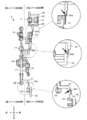
- the left view which shows the structural example of a plastic model kit.
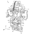
- the figure for explaining the assembly procedure of the plastic model kit The figure for explaining the assembly procedure of the plastic model kit.
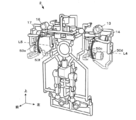
- the figure for explaining the assembly procedure of the plastic model kit The figure for explaining the assembly procedure of the plastic model kit.
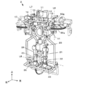
- the figure for explaining the assembly procedure of the plastic model kit The figure which shows the modification of a bending part.
- FIG. 1 is a front view showing a configuration example of a plastic model kit 2 to which the present invention is applied.
- FIG. 2 is a left side view of the kit.
- the plastic model kit 2 is a kit that is integrally molded by, for example, injection molding and becomes a human model when assembly is completed.
- Parts include chest part 10, head part 11, left shoulder part 12, left upper arm part 13, left forearm part 14, right shoulder part 15, upper right arm part 16, right forearm part 17, waist part 20 that also functions as the abdomen, upper left A thigh part 21, a left lower leg part 22, a left foot part 23, an upper right thigh part 24, a right lower leg part 25, and a right foot part 26 are provided.
- the corresponding part is shaded so that it can be easily recognized that it is a part.
- the plastic model kit 2 of the present embodiment is basically assembled by fitting parts. Therefore, parts that can be fitted to each other are provided between the parts to be combined.
- the chest part 10 is provided with a head ball joint 10b, and the head part 11 is fitted with the ball joint. Socket part.
- the chest part 10 is provided with a shoulder ball joint 10a, and the left shoulder part 12 is provided with a shoulder socket 12a.
- the left shoulder part 12 is provided with an arm ball joint 12b, and the left upper arm part 13 is provided with an arm socket 13a.
- the left forearm part 14 is provided with an elbow shaft 14a.
- the waist part 20 is provided with an upper leg ball joint 20a, and the left upper leg part 21 is provided with an upper leg socket 21a.
- the left upper leg part 21 is provided with a knee ring 21b, and the left lower leg part 22 is provided with a knee axis 22a.
- the left foot part 23 is provided with a heel ball joint 22b, and the left foot part 23 is provided with a heel socket 23a.
- the plastic model kit 2 of the present embodiment has a plurality of part molding layers.
- the “part molding layer” here means a planar layer in which parts are arranged (in many cases, a mating surface of a mold).
- the first part molding layer is on the forefront (frontmost surface), and the chest part 10, the waist part 20, the left forearm part 14, the right The forearm part 17, the left lower leg part 22, and the right lower leg part 25 are molded and arranged in the first part molding layer.
- a second part molding layer at a position behind (behind) the first part molding layer, head part 11, left shoulder part 12, left upper arm part 13, right shoulder part 15, upper right arm part 16, upper left part.
- the thigh part 21, the left foot part 23, the upper right thigh part 24, and the right foot part 26 are formed and arranged with this second part molding layer.
- the molding layers of the head part 11, the left shoulder part 12, and the left upper arm part 13 can be further divided. Further, the molding layers of the upper right arm part 16 and the left upper thigh part 21 can be divided, or the molding layers of the left upper thigh part 21, the left foot part 23, the upper right thigh part 24, and the right foot part 26 can be divided.
- each part is supported by the support portion 40.
- the support part 40 includes a main runner 41 that functions as a common part for passing resin flowing into each part, a sub-runner 42 that is connected to each part via the gate 43, and a gate 43. Further, a bent portion 50 that connects between the main runner 41 and the sub runner 42 or between adjacent sub runners 42 is one of the support portions 40.
- the main runner 41 and the sub runner 42 are drawn as relatively thick white belts that are looped in a maze so that these parts can be easily identified, and the gate 43 has a short width adjacent to the part. It is drawn as a narrow white belt. And the part applicable to the bending part 50 is given the cross hatching.
- the head part 11, the left shoulder part 12, and the right shoulder part 15 are integrated with the sub-runner 42 to constitute a “unit”, and the main runner 41 on the chest part 10 side with the bent portions 50 a and 50 b. It is connected with.
- the sub runner 42 that supports the left forearm part 14 is connected to the sub runner 42 that supports the left upper arm part 13 by the bent portions 50 c and 50 d to form a “unit”.
- the unit is connected to the main runner 41 on the left side of the chest part 10 with bent portions 50p and 50q.
- the sub-runner 42 that supports the right forearm part 17 is connected to the sub-runner 42 that supports the right upper arm part 16 by the bent portions 50 e and 50 f to form a “unit”.
- the unit is connected to the main runner 41 on the right side of the chest part 10 with the bent portions 50r and 50s.
- the sub runner that supports the left upper thigh part 21 is connected to the main runner 41 via the bent portions 50g and 50h.
- the sub runner that supports the upper right thigh part 24 is connected to the main runner 41 via the bent portions 50j and 50k.
- sub runner 42 that supports the left foot part 23 and the right foot part 26 is connected to the main runner 41 through three bent portions 50l, 50m, and 50n.
- the bent portions 50 (50a, 50b,%) are narrower than the main runner 41 and the sub runner 42, and are made to be weak against bending.
- the bent portion 50 has a shape that can be easily bent in a specific direction, and an imaginary line that connects a plurality of adjacent bent portions 50 having the same bending direction is a “folding axis”.
- the left bent portion 50a and the right bent portion 50b are located at the same height at the upper ends of the two main runners 41 that run up and down on the left and right sides of the chest part 10.
- These bent portions have a shape that can be easily bent toward the front side of the drawing in FIG. 1 (a shape that can be easily bent leftward in the drawing in FIG. 2).
- the left bent portion 50a and the right bent portion 50b are substantially L-shaped so that the bent portion is located near the base of the main runner 41. (Refer to the black arrow in the enlarged view at the top of FIG. 2), stress tends to concentrate on the curved portion.
- the turn position is determined.
- An imaginary line connecting these becomes a folding line (a one-dot chain line in FIG. 1 in the left-right direction), and the head part 11, the left shoulder part 12, and The right shoulder part 15 is swung toward the chest part 10 about the bending axis, and these can be fitted and assembled.
- the bending part 50 of this embodiment is designed to be bent at a predetermined angle of less than 180 degrees, more preferably at an angle of around 90 degrees.
- it can be 180 degrees or more, but if the angle required for the bending is wide, it is difficult for the user to imagine that the bending is performed there.
- the angle is less than 180 degrees, preferably around 90 degrees.
- the unit composed of the head part 11, the left shoulder part 12, and the right shoulder part 15 is tilted to the chest part 10 side by a folding line L1 connecting the bent part 50a and the bent part 50b. Bend it.
- the head part 11 is put on the head ball joint 10b of the chest part 10 by being pushed in appropriately.
- the left shoulder part 12 and the right shoulder part 15 are each put on the shoulder ball joint 10a, and are fitted by being pushed in appropriately.
- the left upper leg part 21 is bent so as to be tilted toward the waist part 20 and the left lower leg part 22 along a folding line L2 connecting the bent part 50g and the bent part 50h.
- the upper thigh socket 21a of the left upper thigh part 21 is fitted to the upper thigh ball joint 20a of the waist part 20, and the knee shaft 22a of the left lower thigh part 22 is inserted into the knee ring 21b of the left upper thigh part 21. It is inserted. That is, the first part (left upper thigh part 21) is configured to be fitted to the second part (waist part 20) and the third part (left lower leg part 22) by one bending.
- the upper right thigh part 24 is folded and fitted so as to be tilted toward the waist part 20 and the right lower leg part 25 at a folding line L3 connecting the bent part 50j and the bent part 50k.
- the appearance is similar to that of a general plastic model kit in which a plurality of parts are connected by a runner and a gate. Nevertheless, assembly is possible by bending at the bent portions 50 (50a, 50b,). When assembling, the parts are not separated from the support part, so you don't have to worry about the assembly posture between the parts.
- the assembly is not completed by one associating work like shellfish matching.
- the second part for example, the left shoulder part 12
- the first part for example, the chest part 10
- the third part for example, the left forearm part 14
- an appropriate degree of difficulty is given by devising the order of bending.
- bent portion 50 (50a, 50b,...) Is provided with a stress concentration portion for generating the folding lines L1 to L8, that is, a point that is easily bent. For this reason, precision is not required for folding itself, and even a child can easily perform appropriate folding.
- the provision of multiple parts molding layers is significant because it gives design flexibility to the layout of parts in order to realize a plastic model kit based on folding.
- the difference in the part molding layer produces an effect of conspicuous presence of the unit to be folded, so that even a user unfamiliar with the plastic model kit can easily understand the portion to be folded.
- the molding layer is one layer, the surface (area in plan view) formed by the entire kit is widened by the number of parts, but the parts can be arranged three-dimensionally by using multiple molding layers, It is also possible to reduce the size of the kit before assembly (area in plan view).
- the support portion includes a common portion (for example, the main runner 41 in FIG. 1), a second branch portion (for example, the sub runner 42 in FIG. 1) connected to the second part, A third branch portion (for example, the sub-runner 42 in FIG. 1) connected to the three parts, and the first bent portion is provided at a connection portion between the common portion and the second branch portion. Is provided at a connecting portion between the common portion and the third branch portion.
- a branch portion can be provided between the bent portion and the part, and therefore, by appropriately setting the length, shape, etc. of the branch portion, the part can be guided to an appropriate position when bent at the bent portion.
- the design freedom of the plastic model kit can be increased.
- a 1st part and a 2nd part are shape
- the first part and the third part are formed with different part forming layers, and the second bent part and the third part are bent by bending the second bent part at a predetermined angle of less than 180 degrees. Can be fitted.
- the first bent portion and the second bent portion have a shape in which at least the thickness in the bending direction is made thinner than the portion that is not bent.
- at least the inner side where the first bent portion and the second bent portion are bent is formed flat.
- the completed form is a human model in the above embodiment, it is needless to say that animals, imaginary monsters, robots, vehicles, weapons, etc. may be used.
- a part may include a part assembled by being separated from the runner.
- FIG. 7 is a view showing a modified example of the bent portion, and is an enlarged view of the unit of the left upper arm part 13 and the left forearm part 14 as seen from the back of the kit.
- FIG. 7 (1) shows before assembly
- FIG. 7 (2) shows after assembly.
- a configuration in which the stress concentration portion is realized by setting the thickness of the bent portions 50t and 50u is also possible. More specifically, it is preferable that at least the thickness in the folding direction is made thinner than the unfolded portion, and at least the inner side to be folded is formed in a planar shape.
Landscapes
- Toys (AREA)
Abstract
比較的容易に組み立てできる全く新しいプラスチックモデルキットの技術の提供。プラスチックモデルキット2は、複数のパーツが支持部(例:メインランナー41、サブランナー42、ゲート43)で支持された状態に一体成形され、第1パーツ(例:胸部パーツ10)と第2パーツ(例:左肩パーツ12)とは、互いに嵌合可能な部位(例:肩ボールジョイント10a、肩ソケット12a)を有し、第2パーツと第3パーツ(例:左上腕パーツ13)とは、互いに嵌合可能な部位(例:腕ボールジョイント12b、腕ソケット13a)を有し、支持部は、第1折り曲げ部(例:折り曲げ部50a,50b)及び第2折り曲げ部(例:折り曲げ部50p,50q)を有し、第1折り曲げ部で折り曲げることで、第1パーツと第2パーツとが嵌合可能となり、第1パーツと第2パーツとが嵌合した状態で第2折り曲げ部で折り曲げることで、第2パーツと第3パーツとが嵌合可能となる。
Description
本発明は、プラスチックモデルキットに関する。
プラスチックモデルキットの多くは、射出成形される。そのため、組み立て前のプラスチックモデルキットには、主たる樹脂の流路となるランナーと、複数のパーツと、ランナーとパーツを結ぶゲートとが一体に構成されている(例えば、特許文献1)。
なかには、プラスチックモデルキットに不慣れな初心者や年少者向けに、極めて組み立てが容易となるものも知られている(例えば、特許文献2)。
特許文献1に代表される従来のプラスチックモデルキットでは、パーツをゲートとの接合部で切り離し、説明書の手順に従って組み立てることとなる。パーツは、全体のごく一部でしかないため、パーツを見ただけでは完成品のどこの構成部材かが分かり難いため、初心者や年少者にとっては、パーツを切り離してみたものの、組み立てるために必要なパーツ同士の正しい組み付け姿勢すらわからない、という事態が生じ得る。
これに対して、特許文献2のプラスチックモデルではランナーが無く、パーツは隣接して配置された2つの主要パーツのみで構成されていると言える。また、この2つの主要パーツも互いがゲートで繋がれており、そのゲートを折り曲げるだけでほぼ完成となる。パーツを切り離す作業が無いので、プラスチックモデルキットに不慣れな初心者や年少者でも簡単に組み立てできる。しかし、この構成では、あまりにも組み立てが容易に過ぎ、組み立てることに面白味のあるプラスチックモデルキットの本来の醍醐味が無い。
すなわち、そもそもプラスチックモデルキットを作る醍醐味は、1つ1つのパーツが完成品のどこを構成するかが分かり難くとも、組み立てが進むにつれて徐々に完成品のイメージに近づいて行く過程を楽しむことにある。特許文献2ほどに組み立て容易では、その本来の醍醐味を味わうことができない。
本発明は、プラスチックモデルキットに不慣れな初心者や年少者であっても比較的容易に組み立てできる新しいプラスチックモデルキットの技術を提供することにある。
本発明のプラスチックモデルキットは、複数のパーツが支持部(例えば、図1のメインランナー41、サブランナー42、ゲート43)で支持された状態に一体成形されたプラスチックモデルキットであって、第1パーツ(例えば、図1の胸部パーツ10)と第2パーツ(例えば、図1の左肩パーツ12)とは、互いに嵌合可能な部位(例えば、図1の肩ボールジョイント10a、肩ソケット12a)を有し、前記第2パーツと第3パーツ(例えば、図1の左上腕パーツ13)とは、互いに嵌合可能な部位(例えば、図1の腕ボールジョイント12b、腕ソケット13a)を有し、前記支持部は、第1折り曲げ部(例えば、図1の折り曲げ部50a,50b)及び第2折り曲げ部(例えば、図1の折り曲げ部50p,50q)を有し、前記第1折り曲げ部で折り曲げることで、前記第1パーツと前記第2パーツとが嵌合可能となり、前記第1パーツと前記第2パーツとが嵌合した状態で前記第2折り曲げ部で折り曲げることで、前記第2パーツと前記第3パーツとが嵌合可能となる。
また、本発明のプラスチックモデルキットにおいて、前記支持部が、共通部(例えば、図1のメインランナー41)と、前記第2パーツに接続された第2枝部(例えば、図1のサブランナー42)と、前記第3パーツに接続された第3枝部(例えば、図1のサブランナー42)とを有し、前記第1折り曲げ部は、前記共通部と前記第2枝部との連結部分に設けられ、前記第2折り曲げ部は、前記共通部と前記第3枝部との連結部分に設けられていることが好ましい。
また、本発明のプラスチックモデルキットにおいて、前記第1パーツと前記第2パーツとが、異なるパーツ成形層で成形されており、前記第1折り曲げ部を180度未満の所定角度で折り曲げることで前記第1パーツと前記第2パーツとが嵌合可能となることが好ましい。
また、本発明のプラスチックモデルキットにおいて、前記第1パーツと前記第3パーツとは、異なるパーツ成形層で成形されており、前記第2折り曲げ部を180度未満の所定角度で折り曲げることで前記第2パーツと前記第3パーツとが嵌合可能となることが好ましい。
また、本発明のプラスチックモデルキットにおいて、前記第1折り曲げ部及び前記第2折り曲げ部は、少なくとも折り曲げ方向の肉厚を、折り曲げない部分よりも薄くした形状を有することが好ましい。
また、本発明のプラスチックモデルキットにおいて、前記第1折り曲げ部及び前記第2折り曲げ部が、少なくとも折り曲げる内方側が平面状に形成されることが好ましい。
本発明によると、プラスチックモデルキットに不慣れな初心者や年少者であっても比較的容易に組み立てできる新しいプラスチックモデルキットの技術を提供することができる。
図1は、本発明を適用したプラスチックモデルキット2の構成例を示す正面図である。図2は、同キットの左側面図である。プラスチックモデルキット2は、例えば射出成形により一体成形され、組み立て完成時には人型モデルとなるキットである。
[パーツの説明]
パーツとしては、胸部パーツ10、頭部パーツ11、左肩パーツ12、左上腕パーツ13、左前腕パーツ14、右肩パーツ15、右上腕パーツ16、右前腕パーツ17、腹部を兼ねる腰部パーツ20、左上腿パーツ21、左下腿パーツ22、左足パーツ23、右上腿パーツ24、右下腿パーツ25、右足パーツ26を備える。図1及び図2では、パーツであることを認識しやすいように、該当部分に網掛けをしている。
パーツとしては、胸部パーツ10、頭部パーツ11、左肩パーツ12、左上腕パーツ13、左前腕パーツ14、右肩パーツ15、右上腕パーツ16、右前腕パーツ17、腹部を兼ねる腰部パーツ20、左上腿パーツ21、左下腿パーツ22、左足パーツ23、右上腿パーツ24、右下腿パーツ25、右足パーツ26を備える。図1及び図2では、パーツであることを認識しやすいように、該当部分に網掛けをしている。
本実施形態のプラスチックモデルキット2は、パーツを嵌め込みで組み立てることを基本としている。よって、組み合わされるべきパーツ間には互いに嵌合可能な部位が備えられている。
例えば、胸部と頭部の連結関係に着目すると、胸部パーツ10に頭部パーツ11を組み付けるために、胸部パーツ10には頭部ボールジョイント10bが備えられ、頭部パーツ11はボールジョイントと嵌着するソケット部を備えている。
次に、左上肢部について着目すると、胸部パーツ10の左上部に左肩パーツ12を組み付けるために、胸部パーツ10には肩ボールジョイント10aが備えられ、左肩パーツ12には肩ソケット12aが備えられている。更に、左肩パーツ12に左上腕パーツ13を組み付けるために、左肩パーツ12には腕ボールジョイント12bが備えられ、左上腕パーツ13には腕ソケット13aが備えられている。更に、左上腕パーツ13に左前腕パーツ14を組み付けるために、左上腕パーツ13には肘リング13bが備えられ、左前腕パーツ14には肘軸14aが備えられている。
更に左下肢部に着目すると、腰部パーツ20に左上腿パーツ21を組み付けるために、腰部パーツ20には上腿ボールジョイント20aが備えられ、左上腿パーツ21には上腿ソケット21aが備えられている。更に、左上腿パーツ21に左下腿パーツ22を組み付けるために、左上腿パーツ21には膝リング21bが備えられ、左下腿パーツ22には、膝軸22aが備えられている。更に、左下腿パーツ22に左足パーツ23を組み付けるために、左下腿パーツ22には踝ボールジョイント22bが備えられ、左足パーツ23には踝ソケット23aが設けられている。
なお、右上肢部及び右下肢部については、左上肢部並びに左下肢部と左右対称なので詳細な説明は省略する。
また、図2に示すように、本実施形態のプラスチックモデルキット2は、複数のパーツ成形層を有している。ここで言う「パーツ成形層」とは、パーツが並ぶ面状の層(多くの場合、型の合わせ面)を意味する。
本実施形態では、組み立て前のプラスチックモデルキット2を正面から見ると、最前面(最も手前の面)に第1パーツ成形層があり、胸部パーツ10や、腰部パーツ20、左前腕パーツ14、右前腕パーツ17、左下腿パーツ22、右下腿パーツ25がこの第1パーツ成形層に成形・配置されている。そして、第1パーツ成形層よりも後ろ(奥方)の位置に第2パーツ成形層があり、頭部パーツ11や、左肩パーツ12、左上腕パーツ13、右肩パーツ15、右上腕パーツ16、左上腿パーツ21、左足パーツ23、右上腿パーツ24、右足パーツ26がこの第2パーツ成形層が成形・配置されている。
より厳密には、同じ第2パーツ成形層であっても、更に頭部パーツ11・左肩パーツ12・左上腕パーツ13それぞれの成形層を分けることができる。また、右上腕パーツ16・左上腿パーツ21それぞれの成形層を分けたり、左上腿パーツ21・左足パーツ23・右上腿パーツ24・右足パーツ26それぞれの成形層を分けることもできる。
[ランナーの説明]
パーツ成形層が複数あったとしても、各パーツは支持部40で支持されている。
支持部40は、各部へ流入する樹脂を通すための共通部として機能するメインランナー41と、ゲート43を介して各パーツと接続するサブランナー42と、ゲート43とを備える。更に、メインランナー41とサブランナー42との間や、隣接するサブランナー42同士の間などを接続する折り曲げ部50も支持部40の1つである。
パーツ成形層が複数あったとしても、各パーツは支持部40で支持されている。
支持部40は、各部へ流入する樹脂を通すための共通部として機能するメインランナー41と、ゲート43を介して各パーツと接続するサブランナー42と、ゲート43とを備える。更に、メインランナー41とサブランナー42との間や、隣接するサブランナー42同士の間などを接続する折り曲げ部50も支持部40の1つである。
図1及び図2では、これら各部の識別が容易となるように、メインランナー41及びサブランナー42は迷路状に巡らされた比較的太い白帯として描かれ、ゲート43はパーツに隣接した短く幅の狭い白帯として描かれている。そして、折り曲げ部50に該当する部位にはクロスハッチングを施している。
具体的には、頭部パーツ11と左肩パーツ12と右肩パーツ15とがサブランナー42で一体となって「ユニット」を構成し、折り曲げ部50a,50bでもって胸部パーツ10側のメインランナー41と繋がっている。
また、胸部パーツ10の左方では、左前腕パーツ14を支持するサブランナー42が折り曲げ部50c,50dによって左上腕パーツ13を支持するサブランナー42と連結して「ユニット」を形成している。そして当該ユニットは、折り曲げ部50p,50qでもって胸部パーツ10の左横のメインランナー41と繋がっている。
同様に胸部パーツ10の右方では、右前腕パーツ17を支持するサブランナー42が折り曲げ部50e,50fによって右上腕パーツ16を支持するサブランナー42と連結して「ユニット」を形成している。そして当該ユニットは、折り曲げ部50r,50sでもって胸部パーツ10の右横のメインランナー41と繋がっている。
また、左上腿パーツ21を支持するサブランナーが折り曲げ部50g,50hを介してメインランナー41と繋がっている。同様に右上腿パーツ24を支持するサブランナーが折り曲げ部50j,50kを介してメインランナー41と繋がっている。
また、左足パーツ23及び右足パーツ26を支持するサブランナー42は、3つの折り曲げ部50l,50m,50nを介してメインランナー41と繋がっている。
[折り曲げ部の説明]
折り曲げ部50(50a,50b,…)は、メインランナー41やサブランナー42よりも狭窄な部位であって、曲げに弱くなるように作られている。折り曲げ部50には、特定の方向に折り曲げし易い形状が与えられており、折り曲げ方向が同じで近接する複数の折り曲げ部50を結ぶ仮想線が「折曲軸」となる。
折り曲げ部50(50a,50b,…)は、メインランナー41やサブランナー42よりも狭窄な部位であって、曲げに弱くなるように作られている。折り曲げ部50には、特定の方向に折り曲げし易い形状が与えられており、折り曲げ方向が同じで近接する複数の折り曲げ部50を結ぶ仮想線が「折曲軸」となる。
例えば、キットの上部に着目すれば、胸部パーツ10の左右で上下に走る2本のメインランナー41の上端の同じ高さ位置に、左方の折り曲げ部50aと、右方の折り曲げ部50bとが設けられている。これらの折り曲げ部は、図1ならば図の手前側へ折り曲げしやすい形状(図2ならば図の左方向へ折り曲げしやすい形状)を有している。より具体的には、左方の折り曲げ部50aと右方の折り曲げ部50bは、側面から見るとメインランナー41との付け根付近に曲部が位置するようにして略L字形状を成しており(図2の最上段の拡大図の黒矢印を参照)、曲部に応力が集中しやすくなっている。つまり、曲がる位置が決められている。そして、これらを結ぶ仮想線(より厳密には曲部を結ぶ線)が折曲線となり(図1の左右方向の一点鎖線)、当該折曲線で折り曲げることで頭部パーツ11、左肩パーツ12、及び右肩パーツ15が折曲軸を中心に胸部パーツ10へ向けて揺動されて、これらの嵌着・組み付けが可能となる。
同様のことは、(1)左前腕パーツ14の左右にある2つの折り曲げ部50c,50d、(2)右前腕パーツ17の左右にある2つの折り曲げ部50e,50f、(3)左上腿パーツ21の右にある2つの折り曲げ部50g,50h、(4)右上腿パーツ24の左にある2つの折り曲げ部50j,50k、(5)左足パーツ23及び右足パーツ26の上にある3つの折り曲げ部50l,50m,50nについても言える。
なお、本実施形態の折り曲げ部50は、180度未満の所定角度、より望ましくは90度前後の角度で折り曲げるように設計されている。勿論、180度以上でも可能であるが、折り曲げに要する角度が広いと、ユーザにそこで折り曲げることをイメージさせにくくなる。プラスチックモデルキット2の初心者や年少者をターゲットユーザとする場合には、180度未満、望ましくは90度前後とするのが好適であろう。
[組み立て手順の説明]
図3~図6は、本実施形態のプラスチックモデルキット2の組み立て手順を解説するための図である。
図3~図6は、本実施形態のプラスチックモデルキット2の組み立て手順を解説するための図である。
<手順1>
先ず図3に示すように、頭部パーツ11と左肩パーツ12と右肩パーツ15とでなるユニットを、折り曲げ部50aと折り曲げ部50bとを結ぶ折曲線L1で、胸部パーツ10側へ倒すように折り曲げる。頭部パーツ11は、胸部パーツ10の頭部ボールジョイント10bに被さり、適当に押し込むことで嵌着する。また、左肩パーツ12及び右肩パーツ15はそれぞれ肩ボールジョイント10aに被さる格好となり、これも適当に押し込むことで嵌着する。
先ず図3に示すように、頭部パーツ11と左肩パーツ12と右肩パーツ15とでなるユニットを、折り曲げ部50aと折り曲げ部50bとを結ぶ折曲線L1で、胸部パーツ10側へ倒すように折り曲げる。頭部パーツ11は、胸部パーツ10の頭部ボールジョイント10bに被さり、適当に押し込むことで嵌着する。また、左肩パーツ12及び右肩パーツ15はそれぞれ肩ボールジョイント10aに被さる格好となり、これも適当に押し込むことで嵌着する。
<手順2>
次に、左上腿パーツ21を、折り曲げ部50gと折り曲げ部50hとを結ぶ折曲線L2で、腰部パーツ20及び左下腿パーツ22の方へ倒すように折り曲げる。この一手順で、左上腿パーツ21の上腿ソケット21aは腰部パーツ20の上腿ボールジョイント20aと嵌着され、左上腿パーツ21の膝リング21bには左下腿パーツ22の膝軸22aが挿入・嵌着される。つまり、第1パーツ(左上腿パーツ21)が、第2パーツ(腰部パーツ20)および第3パーツ(左下腿パーツ22)と一回の折り曲げで嵌合するように構成されている。
次に、左上腿パーツ21を、折り曲げ部50gと折り曲げ部50hとを結ぶ折曲線L2で、腰部パーツ20及び左下腿パーツ22の方へ倒すように折り曲げる。この一手順で、左上腿パーツ21の上腿ソケット21aは腰部パーツ20の上腿ボールジョイント20aと嵌着され、左上腿パーツ21の膝リング21bには左下腿パーツ22の膝軸22aが挿入・嵌着される。つまり、第1パーツ(左上腿パーツ21)が、第2パーツ(腰部パーツ20)および第3パーツ(左下腿パーツ22)と一回の折り曲げで嵌合するように構成されている。
同様に、右上腿パーツ24を、折り曲げ部50jと折り曲げ部50kとを結ぶ折曲線L3で、腰部パーツ20及び右下腿パーツ25の方へ倒すように折り曲げて嵌合させる。
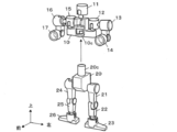
<手順3>
図4に示すように、次に左前腕パーツ14を、折り曲げ部50cと折り曲げ部50dとを結ぶ折曲線L4で、左上腕パーツ13の方へ起こすように折り曲げる。これにより、肘軸14aが肘リング13bに嵌入することになる。同様に、右前腕パーツ17を、折り曲げ部50eと折り曲げ部50fを結ぶ折曲線L5で、右上腕パーツ16の方へ起こすように折り曲げて、両者を嵌合・組み付ける。
図4に示すように、次に左前腕パーツ14を、折り曲げ部50cと折り曲げ部50dとを結ぶ折曲線L4で、左上腕パーツ13の方へ起こすように折り曲げる。これにより、肘軸14aが肘リング13bに嵌入することになる。同様に、右前腕パーツ17を、折り曲げ部50eと折り曲げ部50fを結ぶ折曲線L5で、右上腕パーツ16の方へ起こすように折り曲げて、両者を嵌合・組み付ける。
<手順4>
この段階でキット上側部に着目すると、先の手順1により左肩パーツ12の腕ボールジョイント12bがキット左側方に突出する格好となっている。この位置は、ちょうど左上腕パーツ13を折り曲げ部50p,50qで折り曲げたとき、腕ソケット13aの揺動線上に位置するように設計されている。
この段階でキット上側部に着目すると、先の手順1により左肩パーツ12の腕ボールジョイント12bがキット左側方に突出する格好となっている。この位置は、ちょうど左上腕パーツ13を折り曲げ部50p,50qで折り曲げたとき、腕ソケット13aの揺動線上に位置するように設計されている。
よって、図5に示すように、左上腕パーツ13を、折り曲げ部50pと折り曲げ部50qを結ぶ折曲線L6で、左肩パーツ12の方へ起こすように折り曲げると両者が嵌合されて組み合わされる。同様に右上腕パーツ16を、折り曲げ部50rと折り曲げ部50sを結ぶ折曲線L7で、右肩パーツ15の方へ起こすように折り曲げると両者が嵌合されて組み合わされる。
<手順5>
次に、左足パーツ23と右足パーツ26とのユニットを、折り曲げ部50l,50m,50nを結ぶ折曲線L8で、上方へ起こすようにして折り曲げると、それぞれ揺動線上に位置する左下腿パーツ22、右下腿パーツ25に嵌合される。
次に、左足パーツ23と右足パーツ26とのユニットを、折り曲げ部50l,50m,50nを結ぶ折曲線L8で、上方へ起こすようにして折り曲げると、それぞれ揺動線上に位置する左下腿パーツ22、右下腿パーツ25に嵌合される。
<手順6>
ゲート43と各パーツとを切り離すと、図6に示すように、人型モデルの上半身と下半身とが出来上がっている。最後に胸部パーツ10の嵌入部10cへ、腰部パーツ20の嵌入軸20cを嵌合させると完成となる。
ゲート43と各パーツとを切り離すと、図6に示すように、人型モデルの上半身と下半身とが出来上がっている。最後に胸部パーツ10の嵌入部10cへ、腰部パーツ20の嵌入軸20cを嵌合させると完成となる。
以上、本実施形態のプラスチックモデルキット2によれば、見かけ上は、ランナーとゲートによって複数のパーツが繋がった一般的なプラスチックモデルキットと同様の外観を有している。それでいながら、折り曲げ部50(50a,50b,…)で折り曲げることで組み立てが可能に構成されている。組み立てに際して、パーツを支持部から切り離さないのでパーツ同士の組み付け姿勢に悩むことはない。
また、貝合わせのごとく1回の付き合わせ作業で組み立てが完成するようなものではない。例えば、第1パーツ(例えば、胸部パーツ10)に第2パーツ(例えば、左肩パーツ12)を嵌合させると第2パーツに第3パーツ(例えば、左前腕パーツ14)が嵌合可能になるように、折り曲げの順番に工夫がなされて適度な難易度が与えられている。
また、折り曲げ部50(50a,50b,…)には、折曲線L1~L8を生み出すための応力集中部すなわち折れ曲げし易いポイントが設けられている。このため、折り曲げること自体には精密さが要求されず、子供でも簡単に適切な折り曲げが可能である。
また、複数のパーツ成形層が設けられていることは、折り曲げを基本としたプラスチックモデルキットを実現する上で、パーツのレイアウトに設計自由度を与えるので意義が大きい。加えて、パーツ成形層の違いは、折り曲げるユニットの存在を目立たせる効果を生み、プラスチックモデルキットに不慣れなユーザであっても折り曲げる対象箇所が分かり易くなる。更には、成形層が1層の場合には、パーツの数だけキット全体の成す面(平面視の面積)は広くなるが、複数の成形層とすることでパーツを立体的に配置できる分、組み立て前のキット状態の大きさ(平面視の面積)を小さくすることもできる。
また、本実施の形態において、支持部が、共通部(例えば、図1のメインランナー41)と、第2パーツに接続された第2枝部(例えば、図1のサブランナー42)と、第3パーツに接続された第3枝部(例えば、図1のサブランナー42)とを有し、第1折り曲げ部は、共通部と第2枝部との連結部分に設けられ、第2折り曲げ部は、共通部と第3枝部との連結部分に設けられたている。これにより、折り曲げ部とパーツとの間に枝部を設けることができるので、枝部の長さや形状等を適宜設定することで、折り曲げ部で折り曲げた時にパーツを適切な位置に導くことができ、プラスチックモデルキットの設計自由度を高めることができる。
また、本実施の形態において、第1パーツと第2パーツとを、異なるパーツ成形層で成形し、第1折り曲げ部を180度未満の所定角度で折り曲げることで第1パーツと第2パーツとを嵌合可能としている。また、本実施の形態において、第1パーツと第3パーツとを、異なるパーツ成形層で成形し、第2折り曲げ部を180度未満の所定角度で折り曲げることで第2パーツと前記第3パーツとを嵌合可能としている。
なお、ここで言う「パーツ成形層」とは、パーツが並ぶ面が複数あることを意味する。つまり、例えば、組み立て前のプラスチックモデルキットを正面から見ると、手前側と奥側とでパーツ群が奥行き違いに配列された構成となる。勿論、層が異なっていても支持部により繋がっている。よって、組み合わされる第nパーツと第n+1パーツ(n=1,2)とで成形層を違えることとで、組み合わせるパーツの存在を浮き立たせることができる。また、成形層が1層の場合には、パーツの数だけキット全体の成す面は広くなるが、複数の成形層とすることでパーツを立体的に配置出来る分、組み立て前のキット状態の大きさ(平面視の大きさ)を小さくすることができる。
また、本実施の形態において、第1折り曲げ部及び第2折り曲げ部は、少なくとも折り曲げ方向の肉厚を、折り曲げない部分よりも薄くした形状を有している。また、本実施の形態において、第1折り曲げ部及び第2折り曲げ部が、少なくとも折り曲げる内方側が平面状に形成されている。このようにすることにより、意図的に応力集中部を設けることで、折り曲げようとされた時に、実際に折り曲げされる位置を高い確率で決めることができる。よって、組み立て時のパーツ同士の不整合を抑制できる。
〔変形例〕
なお、本発明の実施形態は上記に限るものではなく、適宜構成要素の追加・変更・省略ができる。
なお、本発明の実施形態は上記に限るものではなく、適宜構成要素の追加・変更・省略ができる。
例えば、上記実施形態では完成形を人型モデルとしているが、動物や、想像上のモンスター、ロボット、乗り物、武器などその他のものでもよいのは勿論である。
また、上記実施形態では全てを折り曲げにより組み立てる構成としたが、一部はランナーから切り離して組み立てる部分を含むとしても良い。
また、折り曲げ部50の構造も、応力集中部を屈曲部として設ける構成に限らない。
例えば、図7は折り曲げ部の変形例を示す図であって、左上腕パーツ13と左前腕パーツ14のユニットを、キット裏面から見た拡大図である。図7(1)が組み立て前、図7(2)が組み立て後を示している。このように、折り曲げ部50t,50uの肉厚の設定により応力集中部を実現する構成も可能である。より具体的には、少なくとも折り曲げ方向の肉厚を折り曲げない部分よりも薄くした形状とし、少なくとも折り曲げる内方側が平面状に形成すると好適である。
例えば、図7は折り曲げ部の変形例を示す図であって、左上腕パーツ13と左前腕パーツ14のユニットを、キット裏面から見た拡大図である。図7(1)が組み立て前、図7(2)が組み立て後を示している。このように、折り曲げ部50t,50uの肉厚の設定により応力集中部を実現する構成も可能である。より具体的には、少なくとも折り曲げ方向の肉厚を折り曲げない部分よりも薄くした形状とし、少なくとも折り曲げる内方側が平面状に形成すると好適である。
2…プラスチックモデルキット、10…胸部パーツ、10a…肩ボールジョイント、10b…頭部ボールジョイント、10c…嵌入部、11…頭部パーツ、12…左肩パーツ、12a…肩ソケット、12b…腕ボールジョイント、13…左上腕パーツ、13a…腕ソケット、13b…肘リング、14…左前腕パーツ、14a…肘軸、15…右肩パーツ、16…右上腕パーツ、17…右前腕パーツ、20…腰部パーツ、20a…上腿ボールジョイント、20c…嵌入軸、21…左上腿パーツ、21a…上腿ソケット、21b…膝リング、22…左下腿パーツ、22a…膝軸、22b…踝ボールジョイント、23…左足パーツ
23a…踝ソケット、24…右上腿パーツ、25…右下腿パーツ、26…右足パーツ、40…支持部、41…メインランナー、42…サブランナー、43…ゲート、50(50a~50t)…折り曲げ部、L1~L8…折曲線
23a…踝ソケット、24…右上腿パーツ、25…右下腿パーツ、26…右足パーツ、40…支持部、41…メインランナー、42…サブランナー、43…ゲート、50(50a~50t)…折り曲げ部、L1~L8…折曲線
Claims (6)
- 複数のパーツが支持部で支持された状態に一体成形されたプラスチックモデルキットであって、
第1パーツと第2パーツとは、互いに嵌合可能な部位を有し、
前記第2パーツと第3パーツとは、互いに嵌合可能な部位を有し、
前記支持部は、第1折り曲げ部及び第2折り曲げ部を有し、
前記第1折り曲げ部で折り曲げることで、前記第1パーツと前記第2パーツとが嵌合可能となり、前記第1パーツと前記第2パーツとが嵌合した状態で前記第2折り曲げ部で折り曲げることで、前記第2パーツと前記第3パーツとが嵌合可能となるプラスチックモデルキット。 - 請求項1において、
前記支持部は、共通部と、前記第2パーツに接続された第2枝部と、前記第3パーツに接続された第3枝部とを有し、
前記第1折り曲げ部は、前記共通部と前記第2枝部との連結部分に設けられ、
前記第2折り曲げ部は、前記共通部と前記第3枝部との連結部分に設けられたプラスチックモデルキット。 - 請求項1または請求項2において、
前記第1パーツと前記第2パーツとは、異なるパーツ成形層で成形されており、
前記第1折り曲げ部を180度未満の所定角度で折り曲げることで前記第1パーツと前記第2パーツとが嵌合可能となるプラスチックモデルキット。 - 請求項1乃至請求項3のいずれか一項において、
前記第1パーツと前記第3パーツとは、異なるパーツ成形層で成形されており、
前記第2折り曲げ部を180度未満の所定角度で折り曲げることで前記第2パーツと前記第3パーツとが嵌合可能となるプラスチックモデルキット。 - 請求項乃至請求項4のいずれか一項において、
前記第1折り曲げ部及び前記第2折り曲げ部は、少なくとも折り曲げ方向の肉厚を、折り曲げない部分よりも薄くした形状を有するプラスチックモデルキット。 - 請求項5において、
前記第1折り曲げ部及び前記第2折り曲げ部は、少なくとも折り曲げる内方側が平面状に形成されたプラスチックモデルキット。
Priority Applications (2)
| Application Number | Priority Date | Filing Date | Title |
|---|---|---|---|
| CN201480045389.XA CN105473199B (zh) | 2013-09-03 | 2014-07-08 | 塑料模型成套组件 |
| HK16106943.7A HK1218895A1 (zh) | 2013-09-03 | 2014-07-08 | 塑料模型成套组件 |
Applications Claiming Priority (2)
| Application Number | Priority Date | Filing Date | Title |
|---|---|---|---|
| JP2013182612A JP5509381B1 (ja) | 2013-09-03 | 2013-09-03 | プラスチックモデルキット |
| JP2013-182612 | 2013-09-03 |
Publications (1)
| Publication Number | Publication Date |
|---|---|
| WO2015033662A1 true WO2015033662A1 (ja) | 2015-03-12 |
Family
ID=51031104
Family Applications (1)
| Application Number | Title | Priority Date | Filing Date |
|---|---|---|---|
| PCT/JP2014/068128 Ceased WO2015033662A1 (ja) | 2013-09-03 | 2014-07-08 | プラスチックモデルキット |
Country Status (4)
| Country | Link |
|---|---|
| JP (1) | JP5509381B1 (ja) |
| CN (1) | CN105473199B (ja) |
| HK (1) | HK1218895A1 (ja) |
| WO (1) | WO2015033662A1 (ja) |
Cited By (1)
| Publication number | Priority date | Publication date | Assignee | Title |
|---|---|---|---|---|
| WO2021039261A1 (ja) * | 2019-08-29 | 2021-03-04 | 株式会社バンダイ | 成形方法及び模型部品 |
Families Citing this family (5)
| Publication number | Priority date | Publication date | Assignee | Title |
|---|---|---|---|---|
| JP5509381B1 (ja) * | 2013-09-03 | 2014-06-04 | 株式会社バンダイ | プラスチックモデルキット |
| JP5855304B1 (ja) * | 2015-04-23 | 2016-02-09 | 株式会社バンダイ | プラスチックモデルキット |
| JP6734045B2 (ja) * | 2015-12-08 | 2020-08-05 | 株式会社バンダイ | プラスチックモデルキット |
| JP7093813B2 (ja) * | 2020-07-03 | 2022-06-30 | 株式会社バンダイ | 玩具部品、関節機構、人形玩具及び装飾部品 |
| JP7083057B1 (ja) * | 2021-04-14 | 2022-06-09 | 株式会社バンダイ | パーツ供給体 |
Citations (5)
| Publication number | Priority date | Publication date | Assignee | Title |
|---|---|---|---|---|
| JPH0646792U (ja) * | 1992-12-02 | 1994-06-28 | 株式会社タカラ | 模型玩具 |
| JPH087915Y2 (ja) * | 1991-12-06 | 1996-03-06 | 株式会社エンジェル | プラスチックモデル |
| JP4406042B1 (ja) * | 2009-03-26 | 2010-01-27 | 洋平 橋浦 | プラスチックモデルキット |
| JP2012187302A (ja) * | 2011-03-11 | 2012-10-04 | Bandai Co Ltd | パーツ供給品 |
| JP5509381B1 (ja) * | 2013-09-03 | 2014-06-04 | 株式会社バンダイ | プラスチックモデルキット |
Family Cites Families (2)
| Publication number | Priority date | Publication date | Assignee | Title |
|---|---|---|---|---|
| KR100466910B1 (ko) * | 1998-08-25 | 2005-01-24 | 가부시끼가이샤 다까라 | 탄성인형체 및 그 제조방법 |
| JP5298275B2 (ja) * | 2007-11-02 | 2013-09-25 | 株式会社マインドクリエイトジャパン | 空気注入式マネキン |
-
2013
- 2013-09-03 JP JP2013182612A patent/JP5509381B1/ja active Active
-
2014
- 2014-07-08 WO PCT/JP2014/068128 patent/WO2015033662A1/ja not_active Ceased
- 2014-07-08 CN CN201480045389.XA patent/CN105473199B/zh active Active
- 2014-07-08 HK HK16106943.7A patent/HK1218895A1/zh unknown
Patent Citations (5)
| Publication number | Priority date | Publication date | Assignee | Title |
|---|---|---|---|---|
| JPH087915Y2 (ja) * | 1991-12-06 | 1996-03-06 | 株式会社エンジェル | プラスチックモデル |
| JPH0646792U (ja) * | 1992-12-02 | 1994-06-28 | 株式会社タカラ | 模型玩具 |
| JP4406042B1 (ja) * | 2009-03-26 | 2010-01-27 | 洋平 橋浦 | プラスチックモデルキット |
| JP2012187302A (ja) * | 2011-03-11 | 2012-10-04 | Bandai Co Ltd | パーツ供給品 |
| JP5509381B1 (ja) * | 2013-09-03 | 2014-06-04 | 株式会社バンダイ | プラスチックモデルキット |
Cited By (2)
| Publication number | Priority date | Publication date | Assignee | Title |
|---|---|---|---|---|
| WO2021039261A1 (ja) * | 2019-08-29 | 2021-03-04 | 株式会社バンダイ | 成形方法及び模型部品 |
| CN114559611A (zh) * | 2019-08-29 | 2022-05-31 | 株式会社万代 | 模型部件 |
Also Published As
| Publication number | Publication date |
|---|---|
| HK1218895A1 (zh) | 2017-03-17 |
| JP2015047414A (ja) | 2015-03-16 |
| JP5509381B1 (ja) | 2014-06-04 |
| CN105473199A (zh) | 2016-04-06 |
| CN105473199B (zh) | 2017-05-24 |
Similar Documents
| Publication | Publication Date | Title |
|---|---|---|
| JP5509381B1 (ja) | プラスチックモデルキット | |
| US6626732B1 (en) | Character toy | |
| US9227145B2 (en) | Planar-part-based toy assembly set | |
| WO2000010665A1 (en) | Elastic doll and production method thereof | |
| US10661193B2 (en) | Chain-shaped splicing toy | |
| CN104815441B (zh) | 人形体的手腕的关节构造及人形体 | |
| CN105148526B (zh) | 塑料模型成套组件 | |
| JP2015047497A (ja) | プラスチックモデルキット | |
| CN104645638B (zh) | 一种可拼接的益智玩具 | |
| US8591283B2 (en) | Action figure | |
| US292919A (en) | Gael axel kihlcreen | |
| US9820518B2 (en) | Glove game and method of use | |
| KR200438669Y1 (ko) | 각도조절 폭이 확대된 허벅지부재를 구비한 구체관절인형 | |
| CN114259737B (zh) | 组装玩具 | |
| KR200460821Y1 (ko) | 구체 관절 인형 | |
| US20140331379A1 (en) | Article of clothing with child interactive devices | |
| JP6734045B2 (ja) | プラスチックモデルキット | |
| JPWO2008099509A1 (ja) | 自立人形とその製造方法 | |
| JPH0548993U (ja) | プラスチックモデル | |
| JP2006346261A (ja) | シート製可動式模型 | |
| CN111991815B (zh) | 模型玩具的连接构造和模型玩具用部件 | |
| CN309970587S (zh) | 直升机玩具 | |
| CN309833095S (zh) | 直升机玩具 | |
| CN309928942S (zh) | 玩具靶 | |
| TWM503931U (zh) | 可動式片狀拼裝立體模型 |
Legal Events
| Date | Code | Title | Description |
|---|---|---|---|
| WWE | Wipo information: entry into national phase |
Ref document number: 201480045389.X Country of ref document: CN |
|
| 121 | Ep: the epo has been informed by wipo that ep was designated in this application |
Ref document number: 14841965 Country of ref document: EP Kind code of ref document: A1 |
|
| NENP | Non-entry into the national phase |
Ref country code: DE |
|
| 122 | Ep: pct application non-entry in european phase |
Ref document number: 14841965 Country of ref document: EP Kind code of ref document: A1 |