WO2015033592A1 - 集塵装置および電気掃除機 - Google Patents
集塵装置および電気掃除機 Download PDFInfo
- Publication number
- WO2015033592A1 WO2015033592A1 PCT/JP2014/054338 JP2014054338W WO2015033592A1 WO 2015033592 A1 WO2015033592 A1 WO 2015033592A1 JP 2014054338 W JP2014054338 W JP 2014054338W WO 2015033592 A1 WO2015033592 A1 WO 2015033592A1
- Authority
- WO
- WIPO (PCT)
- Prior art keywords
- dust
- filter
- dust collector
- vacuum cleaner
- transmission
- Prior art date
- Legal status (The legal status is an assumption and is not a legal conclusion. Google has not performed a legal analysis and makes no representation as to the accuracy of the status listed.)
- Ceased
Links
Images






Classifications
-
- A—HUMAN NECESSITIES
- A47—FURNITURE; DOMESTIC ARTICLES OR APPLIANCES; COFFEE MILLS; SPICE MILLS; SUCTION CLEANERS IN GENERAL
- A47L—DOMESTIC WASHING OR CLEANING; SUCTION CLEANERS IN GENERAL
- A47L9/00—Details or accessories of suction cleaners, e.g. mechanical means for controlling the suction or for effecting pulsating action; Storing devices specially adapted to suction cleaners or parts thereof; Carrying-vehicles specially adapted for suction cleaners
- A47L9/10—Filters; Dust separators; Dust removal; Automatic exchange of filters
- A47L9/12—Dry filters
- A47L9/122—Dry filters flat
-
- A—HUMAN NECESSITIES
- A47—FURNITURE; DOMESTIC ARTICLES OR APPLIANCES; COFFEE MILLS; SPICE MILLS; SUCTION CLEANERS IN GENERAL
- A47L—DOMESTIC WASHING OR CLEANING; SUCTION CLEANERS IN GENERAL
- A47L5/00—Structural features of suction cleaners
- A47L5/12—Structural features of suction cleaners with power-driven air-pumps or air-compressors, e.g. driven by motor vehicle engine vacuum
- A47L5/22—Structural features of suction cleaners with power-driven air-pumps or air-compressors, e.g. driven by motor vehicle engine vacuum with rotary fans
- A47L5/36—Suction cleaners with hose between nozzle and casing; Suction cleaners for fixing on staircases; Suction cleaners for carrying on the back
- A47L5/362—Suction cleaners with hose between nozzle and casing; Suction cleaners for fixing on staircases; Suction cleaners for carrying on the back of the horizontal type, e.g. canister or sledge type
-
- A—HUMAN NECESSITIES
- A47—FURNITURE; DOMESTIC ARTICLES OR APPLIANCES; COFFEE MILLS; SPICE MILLS; SUCTION CLEANERS IN GENERAL
- A47L—DOMESTIC WASHING OR CLEANING; SUCTION CLEANERS IN GENERAL
- A47L9/00—Details or accessories of suction cleaners, e.g. mechanical means for controlling the suction or for effecting pulsating action; Storing devices specially adapted to suction cleaners or parts thereof; Carrying-vehicles specially adapted for suction cleaners
- A47L9/10—Filters; Dust separators; Dust removal; Automatic exchange of filters
- A47L9/16—Arrangement or disposition of cyclones or other devices with centrifugal action
- A47L9/1658—Construction of outlets
- A47L9/1666—Construction of outlets with filtering means
-
- A—HUMAN NECESSITIES
- A47—FURNITURE; DOMESTIC ARTICLES OR APPLIANCES; COFFEE MILLS; SPICE MILLS; SUCTION CLEANERS IN GENERAL
- A47L—DOMESTIC WASHING OR CLEANING; SUCTION CLEANERS IN GENERAL
- A47L9/00—Details or accessories of suction cleaners, e.g. mechanical means for controlling the suction or for effecting pulsating action; Storing devices specially adapted to suction cleaners or parts thereof; Carrying-vehicles specially adapted for suction cleaners
- A47L9/10—Filters; Dust separators; Dust removal; Automatic exchange of filters
- A47L9/16—Arrangement or disposition of cyclones or other devices with centrifugal action
- A47L9/1683—Dust collecting chambers; Dust collecting receptacles
-
- A—HUMAN NECESSITIES
- A47—FURNITURE; DOMESTIC ARTICLES OR APPLIANCES; COFFEE MILLS; SPICE MILLS; SUCTION CLEANERS IN GENERAL
- A47L—DOMESTIC WASHING OR CLEANING; SUCTION CLEANERS IN GENERAL
- A47L9/00—Details or accessories of suction cleaners, e.g. mechanical means for controlling the suction or for effecting pulsating action; Storing devices specially adapted to suction cleaners or parts thereof; Carrying-vehicles specially adapted for suction cleaners
- A47L9/20—Means for cleaning filters
Definitions
- the present invention relates to a dust collector that removes sucked dust in Sorachi and collects the dust, and a vacuum cleaner that is detachably provided with a dust collector.
- a so-called cyclonic vacuum cleaner having a cyclone dust collecting device that centrifuges dust by swirling sucked air in a dust collecting container is known (see, for example, Patent Document 1). Further, the cyclone dust collector is provided with a filter for further filtering the air after the dust is centrifuged. Thereby, the fine dust which was not centrifuged is collected with a filter.
- the suction air volume decreases due to clogging of the filter. Therefore, in order to maintain a high dust collecting power, it is necessary to remove the filter to prevent clogging.
- Patent Document 1 includes a dust removal mechanism that removes dust from the filter.
- This dust removal mechanism is configured to rotate the dust removal member that vibrates the filter, and to vibrate the filter during the rotation, thereby removing the collected and attached dust. Thereby, dust removal of a filter is performed by rotating a dust removal member as needed.
- the dust removing mechanism described in Patent Document 1 described above includes a dust removing member provided with a contact member that comes in contact with the filter and vibrates in a support portion that is rotatably provided with respect to the held filter.
- This dust removing member is provided in a ring shape so as to surround the outer periphery of a filter having a circular planar shape, and a gear is integrally provided in the frame body.
- the gear is engaged with a speed reduction mechanism composed of a plurality of gears that reduce and transmit the rotation of the drive gear (drive gear) fixed to the rotation shaft of the drive motor constituting the drive unit disposed on the cleaner body side. It is provided as such.
- the dust removing mechanism has a large structure including a speed reduction mechanism that meshes with the drive gear on the cleaner body side for rotating the dust removing member, and a dust removing member that includes a gear provided in a ring shape. For this reason, the entire dust collecting device that separates and accommodates dust having a dust removing mechanism tends to be large, and accordingly, the vacuum cleaner is also large.
- the present invention has been made in view of the above circumstances, and an object of the present invention is to provide a dust collector including a dust removing mechanism for a filter that can reduce the size of the dust collector, and a vacuum cleaner provided with the dust collector detachably. Is to provide.
- the dust collector of the present invention provides a cyclone dust collector in which the dust removing mechanism for removing dust from the filter is simplified as much as possible, and at the same time contributes to the miniaturization of the vacuum cleaner. Objective.
- a dust collecting apparatus including a dust collecting container for collecting dust separated from dust contained in air,
- the dust collector is An exhaust filter provided at the top of the dust collecting container for exhausting the separated air;
- a filter dust removing mechanism that is provided on the exhaust filter and vibrates the exhaust filter;
- a transmission unit that is provided at the bottom of the dust collecting container and connected to the drive unit to transmit the driving force of the drive unit;
- a transmission mechanism that transmits the driving force of the transmission unit to the filter dust removal mechanism.
- the dust collector of the present invention since the dust removing member that removes the filter can be driven from the lower part of the dust collector, the transmission mechanism that drives the dust removing mechanism is accommodated within the projection area of the dust collector. Is possible. As a result, the entire dust collector can be reduced in size, and thus the vacuum cleaner can be reduced.
- FIG. 3 is a central sectional view of the cleaner body shown in FIG. 2.
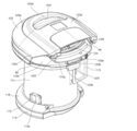
- the perspective view of the cyclone dust collector which shows the external appearance of the state removed from the cleaner body concerning this invention, and was visually observed from the mounting surface side. Sectional drawing of the cyclone dust collector concerning this invention.
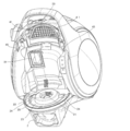
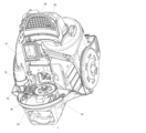
- the perspective view which shows the cleaner body in the state which removed the cyclone dust collector shown in FIG. The perspective view which shows the structure of the drive part for driving the dust removal mechanism of the filter of this invention in the cleaner body shown in FIG.
- FIG. 1 is a perspective view showing an external appearance of the electric vacuum cleaner A according to the embodiment of the present invention.
- the electric vacuum cleaner A is schematically configured to include a vacuum cleaner body 1, a suction port 2, a connection pipe 3, a connection hose 4, an operation handle 5 provided on the connection pipe 3, and the like.
- the vacuum cleaner main body 1 is provided with an electric blower 30 (not shown in FIG. 3) that is not shown in FIG. 1 and a detachable attachment that separates and collects dust contained in the air by the suction operation of the electric blower unit 30.
- a cyclone dust collecting device 10 using a cyclone system, a control device 6 and the like are incorporated.
- the cyclone dust collector 10 will be described in detail later.
- the cyclone dust collector is described as a dust collector.
- the electric blower 30 has a blower fan for performing intake air and a blower drive motor that rotationally drives the blower fan.
- the control device 6 includes control devices such as a CPU, a RAM, and a ROM, and comprehensively controls the electric vacuum cleaner A. Specifically, in the control device 6, the CPU executes various processes in accordance with a control program stored in the ROM.
- the operation handle 5 is provided with an operation switch (not shown) for allowing the user to operate the vacuum cleaner A and to select an operation mode.
- a display unit (not shown) such as an LED for displaying the current state of the electric vacuum cleaner A is also provided in the vicinity of the operation switch.
- the vacuum cleaner main body A is connected to the suction port through the connection hose 4 connected to the connection portion 7 provided at the front end of the vacuum cleaner main body 1 and the connection pipe 3 connected to the connection hose 4. Connected to the unit 2.
- the electric blower 30 built in the cleaner main body 1 is operated, whereby the intake air from the suction port portion 2 is performed.
- the air is introduced from the connection portion 7 through the suction path indicated by the broken-line arrow Y into the dust collector 10 from the air intake 31 of the cleaner body.
- dust collector 10 dust is centrifuged from the sucked air.
- the air after the dust is separated by the dust collector 10 passes through an exhaust path indicated by a solid line arrow Z from the exhaust port 8 provided at the rear portion of the cleaner body 1 through the exhaust port 32 of the exhaust duct unit. Exhausted. A part of the exhaust path cools the control device 6 via the control device 6.
- the air containing the sucked dust is introduced from the intake port 31 to the dust collector 10 through the suction path Y communicating with the connection portion 7.
- the air from which the dust has been separated from the dust collector 10 passes through the exhaust inlet 33 of the exhaust duct 32 provided at the upper part of the cleaner body 1, and then goes to the outside through the exhaust path Z to the exhaust port 8. And exhausted.
- the dust collector 10 will be described in detail with reference to FIGS. 2 to 5 and FIGS. 9 to 12.
- the dust collector 10 is mounted on the cleaner body 1, and the central axis C of the dust collector 10 is inclined to the electric blower 30 side by about 20 ° with respect to the horizontal plane.
- the With the arrangement at such an angle the width in the height direction of the cleaner body 1 and the front-rear direction in FIG. 3 can be designed in a compact manner. For example, if it is inclined to exceed 30 °, the height direction can be suppressed, but the width direction becomes longer. On the contrary, the height is increased when the tilt is not performed or when the tilt is 10 ° or less. Therefore, the cleaner body 1 can be designed in a compact manner by tilting it around 20 °.
- the dust collector 10 includes a dust collector main body 11 including a dust collection cup (dust collector) 111 having an upper opening, and a filter unit 12 that is detachably attached to the upper opening of the dust collector 111. As shown in the perspective view of FIG. 9 as a whole, the filter unit 12 is detachably connected to the dust collector body 11. To connect, a male screw part 111b is attached to the upper opening of the dust collecting container 111 as shown in FIG. 12, and a female screw part 123i is screwed to the male screw part 111b as shown in FIG. The upper cover 123 that constitutes the filter unit 12 described in detail in FIG.
- the dust collector main body 11 has a cylindrical dust collecting container 111 in which an inlet 113 for introducing air containing dust is formed.
- the upper part of the dust collecting container 111 is opened, and a male screw 111b is formed on the outer peripheral surface of the opening end.
- the lower part (bottom) of the dust collecting container 111 is also opened.
- a bottom cover 114 is provided at the bottom of the dust collecting container 111 so as to be openable and closable. Further, the bottom cover 114 is provided with a first rotation transmission mechanism 50 which is a feature of the present invention described in detail below. Details of the rotation transmission mechanism 10 will be described later.
- the configuration of the bottom cover 114 will be described with reference to FIG.
- the bottom cover 114 is pivotally attached to the dust collection container 111 via a shaft portion (not shown) supported by the shaft support portion 112 so that the bottom cover 114 can be opened and closed with respect to the dust collection container 111.
- the bottom lid 114 is provided with a locking portion 114a formed of a through hole formed outside the dust collecting container 111.
- a locking portion 115 for locking is movably provided on the flange portion 111a protruding outward from the lower part of the dust collecting container 111.
- the locking portion 115 is provided with an engaging portion 115a that penetrates the engaging portion 114a and engages with the engaging portion. Further, the lock portion 115 is integrally provided with an operation portion 115b on the side opposite to the engagement portion 115a.
- the lock portion 115 is covered with a cover 116 including the flange portion 111a of the dust collecting container 111, and only the operation portion 115b is exposed to the outside.
- the lock mechanism includes the locking portion 115 including the locking portion 114a and the engaging portion 115a.
- the bottom lid 114 is engaged with the engaging portion 115a by the locking mechanism, and the locked state is maintained by the urging force of a spring (not shown). Therefore, the lower opening of the dust collecting container 111 is closed by the bottom lid 114.
- the lock part 115 is moved (operated) to the right side against the biasing force in FIG. 4, for example, the engagement part 115a is disengaged from the locking part 114a, and the lock is released. Thereby, the bottom cover 114 is opened by its own weight or the urging force of a spring provided at the pivotally attached portion, and the dust collected in the dust collecting container 111 can be discarded.
- the lock 115 is temporarily moved in the direction opposite to the urging direction (for example, the right direction in FIG. 4), and moved in the urging direction when the bottom cover comes into contact with the lower edge of the dust collecting container 111.
- the locked state is maintained by engaging the engaging portion 115a with the engaging portion 114a.
- the rotation transmission mechanism 50 is rotatably provided in an opening 114b formed in the center portion of the bottom cover 114. As shown in FIGS. 3 and 5, the opening 114 b is formed in a cylindrical shape protruding upward. A receiving portion 114c that functions as a bearing of the rotation transmission mechanism 50 is integrally provided on the inner surface of the opening 114b.
- the receiving part 114c is formed in a cylindrical shape as shown in FIG. 3, for example.
- a support part 51 having an opening substantially matching the inner diameter of the cylinder of the receiving part 114c and having a league-shaped recess that fits into the receiving part 114c is rotatably provided.
- a transmission gear 52 for transmitting rotation is provided via a coil spring 53 below the support portion 51.
- An annular lower seal material 54 is provided to seal between the lower surface of the bottom lid 114 and the transmission gear 52.
- the lower seal material 54 is fitted and fixed between the opening 114 b of the bottom lid 114 and the receiving portion 114 c, and the lower surface is in close contact with the transmission gear 52.
- the upper part of the coil spring 13 is in contact with a flange 51a formed on the outer periphery of the support part 51, the lower part is fitted in an annular hole 12a formed in an annular shape in the transmission gear 12, and is in contact with the bottom surface thereof. It is interposed between the support part 51 and the transmission gear 52.
- the transmission gear 52 is urged downward by the action of the urging force of the coil spring 53.
- the connecting portion 55 is provided in the opening portion 114 b via the upper seal material 56.
- the connecting portion 55 is integrally formed with a ring-shaped flange portion 55a at substantially the center in the vertical direction, and the upper seal material 16 is fitted and fixed to the flange portion 15a.
- the outer peripheral surface of the upper seal material 16 is in contact with the opening 114b and seals the dust collection region of the dust collection container 111.
- the upper surface of the upper seal material 16 is provided in a state exposed to the dust collecting container 111, and a lower end of a compression portion constituting a second rotation transmission mechanism to be described later contacts and seals between the members. It has a function.
- the connecting portion 55 is integrally provided with a connecting body 55b that protrudes in a cross shape so that the upper portion is connected to a second rotation transmission mechanism for transmitting rotation to the dust removal mechanism, and a shaft portion 55c that protrudes downward.
- the shaft portion 55c passes through the opening of the receiving portion 114c of the opening portion 114b, the corresponding portion is cylindrical, the lower portion is a quadrangular prism shape, and four protrusions projecting from each surface of the quadrangular prism are provided. It has been.
- An opening is formed in the support portion 51 so as to match the lower shape of the shaft portion 15c, and a coupling portion 52b having an opening that matches the lower shape of the shaft portion 15c is also opened in the transmission gear 52. Therefore, the transmission gear 52 is connected to the central portion of the connecting portion 55 with a screw 57 for fixing via the coil spring 53, and is rotatably connected via the receiving portion 114c of the opening 114b of the bottom lid 114. Is done.
- the transmission gear 52 is provided on the bottom surface of the dust collector 10, in this embodiment, the bottom lid 114 of the dust collector 111, and the dust collector 111 is sealed with the upper and lower sealing materials 56 and 54. .
- the bottom cover 114 that can be opened and closed and the dust collection container 111 are sealed by attaching an annular sealing material to the lower surface of the collar portion of the dust collection container 111 (not shown). Maintaining hermetic seal.
- the cleaner body 1 side meshes with a transmission drive gear 75 (see FIG. 6), which will be described later, constituting a drive unit serving as a drive source. That is, as shown in FIG. 6 with the dust collector 10 removed from the cleaner body 1, the cleaner body 1 is provided with a mounting table 20 that receives the bottom cover 114 of the dust collector 10. A part of the transmission drive gear 75 is provided on the mounting table 20 so as to be exposed.
- the filter unit 12 is detachably attached to the exhaust filter 121 shown in FIG. 10, the filter case 122 shown in FIG.
- a filter cover 123 that covers the exhaust-side filter 121, an inner cylinder portion 124 that is connected to the lower portion of the filter case 122 with screws 42 shown in FIG. 3 and the like, and vents the air after cyclone separation to the exhaust-side filter,
- a first dust removing mechanism 125 which is located above the side filter 121 and removes dust by vibrating the filter; and a second dust removing mechanism for removing dust accumulated in the filter case 122 by the dust removing mechanism 125.
- the exhaust-side filter 121 includes a filter main body 121a made of a spirally folded HEPA filter, an annular frame 121b that holds the filter main body 121a, a central boss portion 121c that penetrates the filter main body 121a in a direction perpendicular to the filter main body 121a, It has the coupling
- a sealing material 128 is fitted and fixed to the outer peripheral surface of the frame body 121b.
- the filter case 122 includes an opening edge 122a whose upper side is opened, a step 122b that is in close contact with and supported by the seal member 127 fitted into the frame 121b of the exhaust-side filter 121, an upper opening edge 122a, and a step A trunk portion 122c having a smaller diameter than the upper opening edge 122a connected to the upper opening edge 122a via 122b, and a tapered portion 122d (see FIG. 5 for details) that decreases in diameter downward from the trunk portion 122c. , And a connecting cylinder part 122e connected to the lower part of the taper part 122d.
- a sealing material 128 is attached to the outer surface of the tapered portion 122d. This sealing material 128 is for closely contacting the dust collecting container 111 described above.
- a knob 122f (see, for example, FIG. 4) is provided on a part of the outer surface of the step 122b between the upper opening edge 122a of the filter case 122 and the body 122c.
- the knob 122f is a part that is picked with a finger when the filter cover 123 is lifted and removed from the filter case 122.
- the entire outer surface of the stepped portion 122b is a locking portion on which a lock claw 123b (see FIG. 5) of a lock mechanism 123a (see FIG. 4) provided on the filter cover 123 described later is hooked.
- the filter cover 123 includes a cover main body 123c, a substantially A-shaped handle portion 123d swingably provided on the upper surface side of the cover main body 123c, and the lock mechanism 123a described above with reference to FIG.
- a concave portion 123e for accommodating the handle portion 123d is provided on the upper surface of the cover body 123c.
- a convex curved surface having no step is formed by the upper surface of the cover main body 123c and the upper surface of the handle portion 123d.
- the position corresponding to the A-shaped hole 123f of the handle portion 123d for inserting the user's hand in the concave portion 123e gradually becomes deeper forward so as to make it easier to grip the handle portion 123d (FIG. 3). reference).
- the cover main body 123c has an exhaust port 123g at its rear part.
- the cover main body 123c is formed with the female screw portion 123i (see FIG. 5) on the inner peripheral surface of a circular lower opening edge 123h (see FIG. 4). Moreover, the female screw part 123i is not formed in the part corresponding to the said locking mechanism 123a of the lower opening edge 123h.
- a bent portion 123j into which the upper opening edge 122a of the filter case 122 is pointed is provided on the inner surface side of the lower opening edge 123h of the cover body 123c and above the lock mechanism 123a.
- an outer peripheral surface of the lower opening edge 123h is provided with a surrounding wall 123k that is long in the circumferential direction, and a locking mechanism 123a is provided on the surrounding wall 123k.
- the lock mechanism 23a includes a lock member 123b (see FIGS. 3 and 5) and a resilient member (not shown).
- the locking member 123b protrudes into the filter case 122 through an opening formed in the lower opening edge 123h by a resilient member, and is locked to the stepped portion 122b. Therefore, the cover main body 123c is maintained in a state of being rotatably attached to the filter case 122. To release the lock, if the lock member 123b is pressed against the elastic member, the lock member 123b can be detached from the step 122b of the filter case 122 and removed.
- the cover main body 123c connected by the lock mechanism 123a is screwed by rotating, Fixed.
- the handle portion 123d the vicinity of the left and right rear ends thereof is pivotally attached to the rear portion of the cover main body 123c by a horizontal shaft (not shown), and locking claws 123l are provided on the left and right rear end surfaces.
- the handle portion 123d can swing around the horizontal axis with respect to the cover body 123c.
- a pair of locking claws 123l are provided in the vicinity of the exhaust port 33 of the exhaust duct portion 32 shown in FIG. It is locked in the locking recess 41 and is mounted as shown in FIG. Thereby, the dust collector 10 is prevented from dropping off from the cleaner body 1 unexpectedly.
- the dust collector 10 is mounted on the mounting table 20, and the transmission gear 52 of the rotation transmission mechanism 50 meshes with a transmission drive gear 75 on the drive unit side described in detail later.
- the front end of the handle portion 1123d swings upward, and the pair of left and right engaging claws 123l swings downward, thereby the handle portion 123d side. Since the pair of locking claws 123l are separated from the locking recess 41, the dust collector 10 can be removed from the cleaner body 1.
- the inner cylinder part 124 has an upper opening edge 124a that expands upward, and a body part 124c having a plurality of slits 124b for allowing the air after centrifugation to pass through.
- a mesh-shaped intake-side filter 124d is wound around the outer periphery of the trunk portion 124c (see FIG. 9).
- the upper opening edge 124 a of the inner cylinder portion 124 is joined to the taper portion 122 d of the filter case 122 by a screw 42.
- a sealing material (not shown) is fixed in advance on the upper edge of the upper opening edge 124 a of the inner cylinder portion 124, and is sealed between the lower surface of the tapered portion 122 d of the filter case 122.
- a seal member 130 is provided at the lower end of the body portion 124 c of the inner cylinder portion 124.
- the dust removing mechanism 125 is rotatably provided on the exhaust filter 121.
- the dust removing mechanism 125 includes a circular frame 125a, three bars 125b as an example of a radial shape in the diameter direction of the frame, and an upper part (downstream) of the filter as shown in FIG. A contact portion 125c in contact with the side) and an attachment portion 125d for attaching the contact portion.
- the contact portion 125c When the dust removing mechanism 125 is rotated in one direction, the contact portion 125c repeatedly contacts and does not contact the peak portion of the filter main body 121a, vibrates the exhaust side filter 121 including the filter main body 121a, and removes adhering dust. Like that.
- the dust removal mechanism 125 is provided with a one-way clutch 125e that transmits rotation in one direction to the center of the frame 125a, that is, the center where the crosspiece 125b intersects.
- a one-way clutch 125e that transmits rotation in one direction to the center of the frame 125a, that is, the center where the crosspiece 125b intersects.
- the rotation in the counterclockwise direction is transmitted, but the rotation in the clockwise direction does not react and does not rotate.
- a conventionally known mechanism may be used, and details thereof are omitted.
- the second dust removal mechanism 126 is provided with two support pieces 126b extending in a curved shape in the outer peripheral direction with respect to the central shaft portion 126a, and the surface of the tapered portion 122d is formed below the support piece 126b.
- a blade portion 126c made of rubber or the like is provided so as to be in close contact.
- the central shaft portion 126a passes through the central boss portion 121c of the exhaust-side filter 121, and is fixed to the rotating portion of the one-way clutch 125e of the upper dust removal mechanism 125, for example, by screws. Therefore, the second dust removing mechanism 126 is connected to the upper dust removing mechanism 125 via the central shaft portion 126a via the one-way clutch 125e.
- a seal member 131 through which the central shaft portion 126 a passes is provided, and this seal member 131 seals between the second dust removal mechanism 126 and the central boss portion 121 c of the exhaust-side filter 121. Is.
- the compression part 127 is provided with a large-diameter cylinder 127a at the top and a small-diameter cylinder 127b at the bottom.
- the large-diameter cylindrical portion 127a has a function of classifying the upper portion of the dust collecting container 111 as a centrifugal separation portion (cyclone portion) and the lower portion as a dust collecting portion that collects dust after separation, and thus the cylindrical shape of the inner cylindrical portion 124. It is formed larger than the diameter.
- the compression portion 127 is formed with a double spiral blade 127c on the outer peripheral surface thereof over the large diameter cylindrical portion 127a and the small diameter cylindrical portion 127b.
- Each spiral blade 112c has a function of compressing dust and dust in the dust collecting container 111 by rotating, and a plurality of small protrusions 127d (see FIG. 5) are formed on the lower surface thereof. These protrusions 127d come into contact with the dust and dust when the spiral blades 127c rotate and are pushed downward, thereby increasing the compressibility of the dust and dust.
- the small-diameter cylindrical portion 127b of the compression portion 127 is in close contact with the upper sealing material 54 provided on the bottom cover 113, and the dust in the dust collecting container 111 is attracted to the inner cylindrical portion 124. Sealing is performed so as to prevent the dust inside the connected compression unit 127 from being mixed.
- the small diameter cylindrical portion 127 b of the compression portion 127 is engaged with and connected to the connecting portion 55 of the first rotation transmission mechanism 50 described above.
- the part 61 is provided integrally.
- the engaging portion 61 is formed as four projecting portions formed in a protruding shape that are inserted between the crosses in association with the cross shape formed in the connecting portion 55.
- Such a connecting mechanism is merely an example, and the present invention is not limited to this. In other words, a conventionally known coupling mechanism can be used as it is for coupling the drive.
- the compression portion 127 When the coupling portion 61 of the compression portion 127 is coupled to the coupling portion 55, the compression portion 127 is rotated by the rotation of the first rotation transmission mechanism 50, and the collected dust is compressed as necessary.
- a flat connecting piece 127e is provided to connect the upper and lower sides of the large diameter cylindrical portion 127a and the small diameter cylindrical portion 127b of the compression portion 127.
- a first rotating cylinder 62 and a second rotating cylinder 63 fixed by screws 43 (see FIG. 5) are supported and fixed to the connecting piece 127e.
- the cylindrical inner diameter of the second rotating cylinder 63 is substantially the same as the inner cylinder inner diameter of the small-diameter cylindrical portion 127b. Further, the inner diameter of the second rotating cylinder 63 and the inner diameter of the first rotating cylinder 62 are substantially the same.
- the first rotating cylinder 62 is provided in the inner cylinder portion 124 so as to be rotatable.
- a support portion 61 a that protrudes outward and is rotatably supported is integrally formed at the upper end of the first rotating cylinder 62 and is held (supported) on the upper opening edge 124 a of the inner cylinder portion 124. Further, the lower end of the connecting cylinder portion 122e of the filter case 122 is supported so as to sandwich the support portion 62a of the first rotating cylinder 62 with the upper opening edge 124a, and the first rotating cylinder 62 is rotatably supported. .
- the first and second rotating cylinders 62 and 63 have substantially the same structure as the inner cylinder part 124, and a slit is formed in the cylindrical body part to allow air to flow.
- connecting pieces 62b protruding above the first rotating cylinder 62 are integrally provided.
- the connecting piece 62b is integrally formed with the first rotating cylinder 62 inward of the support portion 62a and inward of the connecting tube portion 122e of the filter case 122.
- the upper second dust removing mechanism 126 is provided with a locking piece 63 so as to protrude downward on each support piece 126b.
- the locking piece 63 is provided so as to be locked to the connecting piece 62b of the first rotating body 62, and is locked with at least two connecting pieces 62b.
- the second rotational force transmission mechanism 60 includes the engaging portion 61 provided integrally with the compression portion 127, the second rotating body 63 fixed (or integrated) with the compression portion 127, and the second rotation body 63.
- the first rotating body 62 fixed to the rotating body 63 and housed in the inner cylinder portion 124, and the second dust removing mechanism 126 that locks with the connecting piece 62b of the first rotating body 62 are provided. It consists of a piece 63.
- the second dust removal mechanism 126 is connected to the first dust removal mechanism 125 via the central shaft portion 126a, and the first dust removal mechanism 125 is rotated via the one-way clutch 125e.
- the drive unit is provided with a mounting table 20 for mounting the dust collector 10 as shown in FIG. 6 described above.
- a concave portion 21 that is recessed in a circular shape is formed at a substantially central portion of the mounting table 20, and an opening is formed on the side of the transmission fan of the concave portion 21, and the drive transmission gear 79 that constitutes the driving portion of the present invention is formed from the opening. Some are protruding.
- FIG. 7 shows a state where the mounting table 20 and the wall surface on the electric blower side are removed
- FIG. 6 shows a development view for explaining the details of the drive unit 70. As shown in FIG.
- the drive unit 70 is all disposed on the cleaner body 1 side, and includes a drive motor 71 that is a drive source, a drive gear 72 that is directly connected to the rotation shaft of the drive motor 71, and a deceleration for reducing the rotation of the drive gear.
- the first reduction gear 73 meshed with the drive gear 72 constituting the mechanism
- the second reduction gear 74 meshed with the first reduction gear 73
- the transmission drive gear 75 constituting the second reduction gear 74 and the two-stage gear.
- the drive unit 70 is disposed on a drive support body 75, and the drive support body 75 is provided on the upper part of the connection part 7 of the cleaner body 1.
- the drive support 70 holds the drive motor 71 and exposes a part of the drive gear 72 to the first reduction gear 73 side, and a first boss that rotatably supports the first reduction gear 73.
- a second boss portion 79 that rotatably supports the portion 78 and the second reduction gear 74 is integrally formed.
- the transmission drive gear 75 that meshes with the transmission gear 52 on the dust collector 10 side of the first transmission rotation mechanism has a two-stage gear structure integrated with the second reduction gear 74 and is rotated around the second boss portion 79.
- the separated air passes through the upper exhaust side filter 122 through the inner cylinder portion 124, passes through the exhaust duct portion from the exhaust port 123g, and passes through the exhaust path Z shown by the solid line in FIG. 8 is exhausted to the outside.
- the drive motor 71 of the drive unit 70 is driven as necessary. Accordingly, the transmission drive gear 75 is rotated through the drive gear 77 and the reduction gears 73 and 74, and the transmission gear 52 provided on the bottom surface of the dust collector 10 is rotated. As a result, in the first rotation transmission mechanism 50, the connecting portion 55 rotates, and the engaging portion 61 of the second rotation transmission mechanism 60 provided in the compression portion 127 connected thereto is rotated. By this rotation, the compression unit 127 provided integrally is rotated, and the spiral blade 127c is rotated in a direction to compress the collected dust. This rotation may be continued during the cleaning period, and the rotation, stop, rotation, etc. may be repeated sequentially at regular intervals. Moreover, you may rotate when the quantity of dust increases.
- the rotation is in a direction in which the spiral blade 127c of the compression unit 127 can be compressed.
- the second dust removal mechanism 126 rotates in the same direction as the rotation direction of the compression unit.
- the first dust removal mechanism 125 does not rotate due to the action of the one-way clutch 125e.
- the drive motor 71 of the drive unit 70 rotates in a direction opposite to that during cleaning for a certain period (for example, about 30 seconds or 1 minute). .
- the compression unit 127 does not compress the dust in the direction opposite to the compression direction by the spiral blade 127c. Since the compression operation is sufficiently compressed during cleaning, even if it is rotated in the reverse direction, it does not affect the compressed dust.
- the first dust removing mechanism 125 is rotated via the one-way clutch 125e to remove the fine dust adhering to the filter and drop it to the bottom lid 113.
- the second dust removing mechanism 126 can also drop and collect the dust that has fallen on the tapered portion 122d from the connecting cylindrical portion 122e to the bottom lid 113.
- the drive unit that drives the dust removal mechanism is provided in the lower part, and the transmission unit that is connected to the drive unit is provided on the bottom surface side of the dust collector 10. Therefore, the dust removing mechanism provided in the filter portion can transmit the rotating portion from the central portion, and the dust removing mechanism can be made small, whereby the dust collector 10 can be formed compactly. From this, as a natural result, the vacuum cleaner body 1 can also be compactly designed with a small design.
- the dust removing mechanism of the dust collector 10 is driven from the bottom.
- the second problem is to make the drive connection portion of the drive portion 60 with the transmission drive gear 75 smooth, more efficiently, and simply mounting the dust collecting device 10, and a configuration for realizing this.
- the second embodiment will be described below.
- the mounting table 20 on which the dust collector 10 is mounted corresponds to the transmission gear 52 whose shape protrudes from the bottom cover (bottom surface) 114 of the dust collector 10 and is exposed.
- a recess 22 into which the transmission gear 52 is inserted is formed.
- the recess 22 is formed with an opening 21 through which a part of the drive transmission gear 75 of the drive unit 70 is exposed.
- the transmission gear 52 provided on the bottom surface of the dust collector 10 may be positioned so as to coincide with the concave portion 22 of the mounting table 20. Thereby, by engaging the engaging claws 123l provided in the handle part 123d of the dust collector 10 described above with the pair of engaging recesses 41 provided in the vicinity of the exhaust port 33 of the exhaust duct part, The dust collector 10 can be easily positioned, held and fixed to the cleaner body 1.
- another second recess 23 is formed on the mounting table 20 on the outer periphery of the recess 22.
- This 2nd recessed part 23 is formed in the inclined surface 24 so that the front part side provided with the connection part 7 is low, and it raises gradually to a back side.
- the bottom surface of the dust collector 10 that is, the bottom cover 114, has a protruding portion 114 f formed on the front bottom surface so It is formed lower than the protrusion 114g on the bottom surface on the rear side.
- an inclined surface 114 h is formed on the bottom surface connected to the front side and the rear side corresponding to the inclined surface 24.
- the dust collector 10 By forming a portion where the height of the bottom surface of the dust collector 10 is different before and after such, and forming the second recess 23 in the mounting table 20 of the cleaner body 1, the dust collector 10 can be made along its shape. By aligning with the mounting table 20, positioning to the cleaner body is facilitated, and the mounting operation of the connecting portion for transmitting the drive is very simple and can be performed reliably.
- the transmission gear 52 protrudes by providing the transmission gear 52 for connecting the drive unit on the bottom surface of the dust collector 10. Therefore, when discarding the collected dust, the dust collector 10 is removed from the cleaner body 1. If the bottom surface of the dust collecting device 10 is placed on a table or the like, the transmission gear 52 may be damaged.
- the protrusion 114 protruding from the transmission gear 52 to the lid 114 on the bottom surface of the dust collector 10, that is, the protrusion 114j and the protrusion 114g are connected to each other as shown in FIG.
- An annular projecting portion made of an inclined surface 114h is provided.
- a protrusion is provided on the entire circumference of the transmission gear 52.
- This protrusion is provided corresponding to the second recess 23 of the mounting table 20 described in the previous second embodiment.
- the effect by 2nd Embodiment can also be show
- the protruding portion may have the same protruding amount as the protruding portion 114j on the entire circumference.
- the transmission gear 52 can be prevented from being damaged even if the dust collector 10 is removed.
- FIGS. 4, 6 and 13 to 15 A fourth embodiment of the present invention will be described with reference to FIGS. 4, 6 and 13 to 15.
- the dust collected by the dust collecting device 10 can be sufficiently compressed. Therefore, the compressed dust acts to push the dust collector upward from the mounting table 20 via the compression unit 127. Therefore, when there is a concern that the dust collecting apparatus 10 cannot be maintained by the locking claw 123l for maintaining the dust collector 10 in a fixed position, a configuration for eliminating the dust collecting apparatus 10 will be described as a fourth embodiment.
- FIG. 13 is a perspective view of the vacuum cleaner main body with the dust collector 10 showing the exhaust port 33 removed
- FIG. 14 is a diagram for explaining the configuration of the fourth embodiment with the dust collector 10 attached.
- FIG. 16 is a partial cross-sectional view of FIG.
- a pair of fixing pieces 45 are provided on the cleaner body 1 side so as to protrude below the locking recess 41.
- the fixed piece 45 is connected to the outer surface of the lower opening edge 123h formed integrally with the cover body 123c on the dust collector 10 side and the inner surface of the upper cover body 123c.
- a pair of restricting members 46 that engage with the fixed piece 45 provided in this manner are integrally provided.
- the upper surface of the restricting member 46 has a concave shape.
- the restricting member 46 is formed so as to contact the lower portion of the fixed piece 45.
- the bottom surface of the dust collector 10, particularly the bottom cover 114 portion, is placed on the mounting table 20.
- the dust collector 10 is inclined to the electric blower 30 side by about 20 ° with respect to the cleaner body 1 as described above, so that the placed dust collector 10 is moved to the cleaner body 1 side. knock down.
- the regulating member 46 is inserted into the lower surface of the fixed piece 45 so as to rotate on the fixed piece 45 on the cleaner body 1 side, the operation can be performed very smoothly.
- an inclined surface 45 a is formed on the lower surface of the protruding end portion of the fixed piece 45.
- the compression unit 127 is driven to compress the dust and the compression rate is greatly increased, the position of the dust collector 10 can be prevented from changing and being displaced.
- the example of the cyclone dust collecting device as the dust collecting device has been described, but not only the cyclone type dust collecting device but also dust in the air is separated and separated.
- the dust can be collected, and the separated air can be used in general vacuum cleaners that remove fine dust through a filter.
Landscapes
- Engineering & Computer Science (AREA)
- Mechanical Engineering (AREA)
- Filters For Electric Vacuum Cleaners (AREA)
Abstract
フィルタ除塵を行なう除塵機構を備えた集塵装置の構成を簡略化し、小型化を可能にする。集塵装置(10)は、集塵容器(111)、該集塵容器(111)の上部に設けられ分離後の空気を排気する排気フィルタ(121)、排気フィルタ(121)の上部に設けられ該排気フィルタ(121)を振動させるフィルタ除塵機構(125)、前記集塵容器(111)の底部に設けられ駆動部(70)と連結され、駆動部(70)の駆動力が伝わる伝達部(52)、前記伝達部(52)の駆動力を前記フィルタ除塵機構(125)に伝達する伝達機構(50,60)、を備えてなる。これにより、外方向に突出する部分がなくなり、構成が簡略化し、小型化になる。
Description
本発明は、吸引された空知中の塵埃を除塵し、これを集塵してなる集塵装置、および集塵装置を着脱可能に設けてなる電気掃除機に関する。
従来から、吸い込まれた空気を集塵容器で旋回させることにより塵埃を遠心分離するサイクロン集塵装置を有する所謂サイクロン式の電気掃除機が知られている(例えば、特許文献1参照)。また、サイクロン集塵装置には、塵埃が遠心分離された後の空気を更に濾過するためのフィルタが設けられる。これにより、遠心分離されなかった細塵がフィルタで捕集される。
ところで、前記電気掃除機では、前記フィルタの目詰まりによって吸い込み風量が低下する。そのため、高い集塵力を維持するためには前記フィルタを除塵して目詰まりを防止する必要がある。
例えば、特許文献1には、フィルタを除塵する除塵機構を備えている。この除塵機構は、フィルタを振動させる除塵部材を回転させ、その回転時にフィルタを振動させることで、捕集され付着している塵埃を除去する構成が開示されている。これにより、必要時に除塵部材を回転させることで、フィルタの除塵が行われる。
上述した特許文献1に記載の除塵機構は、保持されたフィルタに対して回転可能に設けられた支持部に、フィルタと接触し振動する接触部材を設けた除塵部材を備える。この除塵部材には、平面形状が円形のフィルタの外周を囲ようにリング状に設けられ枠体に歯車が一体に設けられている。この歯車には、掃除機本体側に配置された駆動部を構成する駆動モータの回転軸に固定された駆動歯車(駆動ギア)の回転を減速して伝える複数の歯車からなる減速機構が、噛み合うようにして設けられている。
したがって、除塵機構は、除塵部材を回転させるための掃除機本体側の駆動ギアと噛み合う減速機構、およびリング状に設けられた歯車を備える除塵部材の構成が大掛な構成となる。そのため、除塵機構を備える塵埃を分離し収容してなる集塵装置全体が大きくなる傾向にあり、これにともない電気掃除機も大きくなる。
本発明は上記事情に鑑みてなされたものであり、その目的とするところは、集塵装置を小さくできるフィルタの除塵機構を備える集塵装置、またこの集塵装置を着脱可能に設ける電気掃除機を提供することにある。
また、本発明の集塵装置は、サイクロン方式を利用する場合、フィルタの除塵を行なう除塵機構をできるだけ簡略化してなるサイクロン集塵装置を提供すると同時に、電気掃除機の小型化に貢献することを目的とする。
上記目的を達成するために、空気に含まれる塵埃から分離された塵埃を集塵する集塵容器を備える集塵装置であって、
前記集塵装置は、
前記集塵容器の上部に設けられ分離後の空気を排気する排気フィルタ、
排気フィルタの上部に設けられ、該排気フィルタを振動させるフィルタ除塵機構、
前記集塵容器の底部に設けられ駆動部と連結され、駆動部の駆動力が伝わる伝達部、
前記伝達部の駆動力を前記フィルタ除塵機構に伝達する伝達機構、を備える。
前記集塵装置は、
前記集塵容器の上部に設けられ分離後の空気を排気する排気フィルタ、
排気フィルタの上部に設けられ、該排気フィルタを振動させるフィルタ除塵機構、
前記集塵容器の底部に設けられ駆動部と連結され、駆動部の駆動力が伝わる伝達部、
前記伝達部の駆動力を前記フィルタ除塵機構に伝達する伝達機構、を備える。
本発明の集塵装置によれば、前記フィルタを除塵する除塵部材を集塵装置の下部から駆動できるようにしたので、集塵装置の投影面積内に、除塵機構を駆動する伝達機構を収めることが可能となる。結果、集塵装置全体を小型化でき、よって、電気掃除機を小さくできる。
以下添付図面を参照しながら、本発明の実施の形態について説明し、本発明の理解に供する。尚、以下の実施の形態は、本発明を具体化した一例であって、本発明の技術的範囲を限定する性格のものではない。
ここに、図1は本発明の実施の形態に係る電気掃除機Aの外観を示す斜視図である。この電気掃除機Aは、掃除機本体1、吸込口部2、接続管3、接続ホース4、接続管3に設けられた操作ハンドル5などを備えて概略構成されている。前記掃除機本体1には、図1には不図示(図3に図示)の電動送風機30、この電装送風機ユニット30の吸引動作により空気に含まれる塵埃を分離し集塵する着脱可能に設けられるサイクロン方式を利用したサイクロン集塵装置10、および制御装置6などが内蔵されている。なお、前記サイクロン集塵装置10については後段で詳述する。以下サイクロン集塵装置を集塵装置として記述する。
前記電動送風機30は、吸気を行うための送風ファン及び該送風ファンを回転駆動する送風駆動モータを有している。前記制御装置6は、CPUやRAM、ROMなどの制御機器を有してなり、前記電気掃除機Aを統括的に制御する。具体的に、前記制御装置6では、前記CPUが前記ROMに記憶された制御プログラムに従って各種の処理を実行する。
なお、前記操作ハンドル5には、ユーザが前記電気掃除機Aの稼働の有無や運転モードの選択操作などを行うための操作スイッチ(不図示)が設けられている。また、その操作スイッチの近傍には、前記電気掃除機Aの現在の状態を表示するLEDなどの表示部(不図示)も設けられている。
電気掃除機本体Aは、該掃除機本体1の前端に設けられた接続部7に接続された前記接続ホース4と、該接続ホース4に接続された前記接続管3とを介して前記吸込口部2に接続されている。前記電気掃除機Aでは、前記掃除機本体1に内蔵された前記電動送風機30が作動されることにより、前記吸込口部2からの吸気が行われる。そして、図3において、接続部7から破線矢印Yで示す吸引経路を経て掃除機本体の吸気口31から集塵装置10へと導入される。この集塵装置10内で、吸い込まれた空気から塵埃が遠心分離される。なお、集塵装置10で塵埃が分離された後の空気は、排気ダクト部の排気口32を介して掃除機本体1の後部に設けられた排気口8から実線矢印Zで示す排気経路を経て排気される。排気経路は、一部が制御装置6を経由して、制御装置6を冷却している。
図7を参照すれば、吸引された塵埃を含む空気は、接続部7と連通する吸引経路Yを経て、吸気口31から集塵装置10へと導入される。集塵装置10より塵埃が分離された空気は、掃除機本体1の上部に設けられている排気ダクト部32の排気導入口33を経て、排気経路Zを経由して排気口8かた外部へと排気される。
(集塵装置)
以下、図2~5、また図9~12を参照しつつ、集塵装置10について詳説する。集塵装置10は、図3に示すように掃除機本体1に装着された状態で、集塵装置10の中心軸Cが、水平面に対して約20°程度電動送風機30側へと傾斜配置される。このような角度での配置により掃除機本体1の高さ方向、及び図3における前後方向における幅を、コンパクトに設計できる。例えば、30°を超えるように傾斜させると、高さ方向を押えることができるが、幅方向が長くなる。逆に、傾斜させない、あるいは10°以下の傾斜では、高さが高くなる。したがって、20°前後に傾斜させることでコンパクトに掃除機本体1を設計できる。
以下、図2~5、また図9~12を参照しつつ、集塵装置10について詳説する。集塵装置10は、図3に示すように掃除機本体1に装着された状態で、集塵装置10の中心軸Cが、水平面に対して約20°程度電動送風機30側へと傾斜配置される。このような角度での配置により掃除機本体1の高さ方向、及び図3における前後方向における幅を、コンパクトに設計できる。例えば、30°を超えるように傾斜させると、高さ方向を押えることができるが、幅方向が長くなる。逆に、傾斜させない、あるいは10°以下の傾斜では、高さが高くなる。したがって、20°前後に傾斜させることでコンパクトに掃除機本体1を設計できる。
集塵装置10の詳細を説明する。集塵装置10は、上方開口部を有する集塵カップ(集塵容器)111を備える集塵部本体11と、集塵容器111の上方開口部に着脱可能に取り付けられるフィルタユニット12とからなる。フィルタユニット12の全体を図9の斜視図に示すように、集塵部本体11を相互に取り外し可能に連結される。連結するために、図12に示すように集塵容器111の上部開口部に雄ネジ部111bを、この雄ネジ部111bにネジ止めされる図5に示すように雌ネジ部123iが、図10において詳細に説明するフィルタユニット12を構成する上部カバー123に形成されている。
〔集塵部本体〕
集塵部本体11は、図4に示すように塵埃を含む空気を導入するための流入口113が形成された円筒状の集塵容器111を有する。集塵容器111は図12に示すように上部が開口されており、その開口端の外周面には、雄ネジ111bが形成されている。集塵容器111は、下部(底)も開口されている。集塵容器111の底は、開閉可能に底蓋114が設けられている。また、底蓋114には、以下に詳細に説明する本発明の特徴でもある第1の回転伝達機構50が設けられている。この回転伝達機構10については後で詳細を説明する。
集塵部本体11は、図4に示すように塵埃を含む空気を導入するための流入口113が形成された円筒状の集塵容器111を有する。集塵容器111は図12に示すように上部が開口されており、その開口端の外周面には、雄ネジ111bが形成されている。集塵容器111は、下部(底)も開口されている。集塵容器111の底は、開閉可能に底蓋114が設けられている。また、底蓋114には、以下に詳細に説明する本発明の特徴でもある第1の回転伝達機構50が設けられている。この回転伝達機構10については後で詳細を説明する。
図12を参照して上記底蓋114の構成を説明する。底蓋114は集塵容器111に対して開閉可能にするために軸支部112に支持された図示しない軸部を介して集塵容器111に枢着されている。また、底蓋114には、集塵容器111より外側に形成した貫通孔からなる係止部114aが設けられている。この係止部114aに対応させて、集塵容器111下部より外方に突出した鍔部111aに、係止用のロック部115が移動可能に設けられている。
ロック部115には、上記係止部114aを貫通し、この係止部に係合する係合部115aが設けられている。またロック部115には、係合部115aと反対側に操作部115bが一体に設けられている。このロック部115は、集塵容器111の鍔部111aを含めてカバー116で覆われ、操作部115bだけが外部に露出される。
以上、係止部114a、係合部115aを含むロック部115でロック機構が構成される。底蓋114はロック機構により係合部115aが係止部114aに係合され、図示しないスプリングの付勢力によりロック状態が維持される。そのため、集塵容器111の下部開口が底蓋114で閉鎖される。ロック部115を、例えば図4において付勢力に抗して、右側へと移動(操作)させると、係合部115aが係止部114aとの係合が解かれ、ロック解除される。これにより、自重、あるいは枢着部に設けられたスプリングの付勢力により底蓋114が開放され、集塵容器111に集塵された塵埃を廃棄することができる。この底蓋114を閉じる操作により、ロック部115が付勢方向と反対(例えば図4で右方向)に一旦移動し、底蓋が集塵容器111の下縁に接すると付勢方向に移動し、係合部115aが係止部114aに係合することでロック状態が維持される。
〔第1の回転伝達機構〕
次に本発明にかかる第1の回転伝達機構50について説明する。この回転伝達機構50は、底蓋114の中心部分に形成された開口部114bに回転可能に設けられている。この開口部114bは、図3および図5に示すように、上方に突出した円筒形状に形成されている。開口部114bの内面には、回転伝達機構50の軸受けとして機能する受部114cが一体に設けられている。
次に本発明にかかる第1の回転伝達機構50について説明する。この回転伝達機構50は、底蓋114の中心部分に形成された開口部114bに回転可能に設けられている。この開口部114bは、図3および図5に示すように、上方に突出した円筒形状に形成されている。開口部114bの内面には、回転伝達機構50の軸受けとして機能する受部114cが一体に設けられている。
受部114cは、例えば図3に示すように円筒形状に形成されている。受部114cの下側には、受部114cの円筒の内径と略一致する開口を有し、受部114cに嵌りこむリーグ形状の凹部が形成された支持部51が回転可能に設けられる。
支持部51の下側には、回転を伝達するための伝達ギア52がコイルスプリング53を介して設けられている。また、底蓋114の下面と伝達ギア52との間をシールするために環状の下シール材54が設けられている。下シール材54は、底蓋114の開口部114bと受部114cとの間に嵌め込まれて固定されており、下面が伝達ギア52と密着している。また、上記コイルスプリング13の上部は、支持部51の外周に形成されている鍔部51aに当接し、下部は伝達ギア12に環状に形成された環状孔12aに嵌り、その底面に当接し、支持部51と伝達ギア52との間に介在されている。コイルスプリング53の付勢力の作用により、伝達ギア52は下方に付勢される。
一方、支持部51の上側、つまり受部114cの上側には、伝達ギア52の駆動力である回転を後で説明するフィルタユニット112の除塵機構を回転させる第2の回転伝達機構に伝達するための連結部55が、上部シール材56を介して開口部114bに設けられている。連結部55は、上下方向のほぼ中央にリング形状の鍔部55aが一体に形成されており、この鍔部15aに上部シール材16が嵌め込まれ、固定されている。上部シール材16は、その外周面が開口部114bに当接し、集塵容器111の集塵領域を密閉している。また、上部シール材16の上面は、集塵容器111に露出した状態で設けられおり、後述する第2の回転伝達機構を構成する圧縮部の下端が当接し、その部材との間を密閉する機能を有する。
連結部55は、上部が除塵機構に回転を伝えるための第2の回転伝達機構と連結するため十字形状に突出した連結体55bと、下部へと突出した軸部55cが一体で設けられている。軸部55cは、開口部114bの受部114cの開口を貫通し、その対応部分が円筒形状で、それより下部が四角柱形状、またその四角柱の各面より突出した4つ突部が設けられている。この軸部15cの下部形状に合致するように支持部51に開口が形成され、また伝達ギア52にも軸部15cの下部形状に合致する開口を有した結合部52bが開口されている。したがって、伝達ギア52は、コイルスプリング53を介在して連結部55の中心部が固定用のビス57にてネジ固定され、底蓋114の開口部114bの受部114cを介して回転可能に連結される。
以上のように伝達ギア52が、集塵装置10の底面、この実施形態では集塵容器111の底蓋114に設けられ、集塵容器111内を上下のシール材56、54で密閉している。
なお、開閉可能な底蓋114と集塵容器111との密閉は、図示していない集塵容器111の鍔部の下面に環状のシール材が取り付けられており、このシール材で底蓋114との密閉を維持している。
また、上記伝達ギア52に対応して掃除機本体1側には、駆動源となる駆動部を構成する後述する伝達駆動ギア75(図6参照)と噛み合う。つまり、集塵装置10を掃除機本体1より取り外した状態を図6に示すように、掃除機本体1にはこの集塵装置10の底蓋114を受ける載置台20が設けられている。この載置台20に上記伝達駆動ギア75の一部が露出するように設けられている。
〔フィルタユニット〕
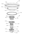
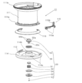
続いて、フィルタユニット12は、図9~11を参照して詳細に説明する。フィルタユニット12は、図10に示す排気側フィルタ121と、この排気側フィルタ121の下部を支持し着脱可能に収納する図11に示すフィルタケース122と、フィルタケース122に着脱可能に取り付けられて前記排気側フィルタ121を覆うフィルタカバー123と、フィルタケース122の下部に図3等に示すネジ42にて連結され、サイクロン分離後の空気を上記排気側フィルタへと通気する内筒部124と、排気側フィルタ121の上部に位置しこのフィルタを振動させて除塵する第1の除塵機構125と、フィルタケース122に除塵機構125にて除塵された塵埃が溜まる塵埃を排除するための第2の除塵機構126と、集塵容器111に集塵された塵埃を圧縮するための圧縮部127と、第1の回転伝達機構50の回転を除塵機構125、第2除塵部126、さらに圧縮部127に伝達するための第2の回転伝達機構60を備えている。
続いて、フィルタユニット12は、図9~11を参照して詳細に説明する。フィルタユニット12は、図10に示す排気側フィルタ121と、この排気側フィルタ121の下部を支持し着脱可能に収納する図11に示すフィルタケース122と、フィルタケース122に着脱可能に取り付けられて前記排気側フィルタ121を覆うフィルタカバー123と、フィルタケース122の下部に図3等に示すネジ42にて連結され、サイクロン分離後の空気を上記排気側フィルタへと通気する内筒部124と、排気側フィルタ121の上部に位置しこのフィルタを振動させて除塵する第1の除塵機構125と、フィルタケース122に除塵機構125にて除塵された塵埃が溜まる塵埃を排除するための第2の除塵機構126と、集塵容器111に集塵された塵埃を圧縮するための圧縮部127と、第1の回転伝達機構50の回転を除塵機構125、第2除塵部126、さらに圧縮部127に伝達するための第2の回転伝達機構60を備えている。
排気側フィルタ121は、つづら折り状のHEPAフィルタからなるフィルタ本体121aと、フィルタ本体121aを保持する円環状の枠体121bと、フィルタ本体121aに対して垂直方向に貫通する中心ボス部121cと、中心ボス部121cと枠体とを結合してなる結合片121dとを有する。なお、枠体121bの外周面にはシール材128が嵌め込まれ、固定されている。
フィルタケース122は、上方が開口された開口端縁122aと、排気側フィルタ121の枠体121bに嵌め込まれたシール材127と密着し支持する段部122bと、上方開口端縁122aと、段部122bを介して上方開口端縁122aに連設された上方開口端縁122aよりも小径の胴部122cと、胴部122cから下方へ向かって縮径するテーパ部122d(詳細は図5参照)と、テーパ部122dの下部に連設された連結筒部122eとを有する。なお、テーパ部122dの外面にはシール材128が取り付けられる。このシール材128は、先に説明した集塵容器111と密着させるためのものである。
また、フィルタケース122の上方開口端縁122aと胴部122cとの間の段部122bの外面の一部には摘み片122f(例えば図4参照)が設けられている。この摘み片122fは、フィルタカバー123を持ち上げてフィルタケース122から取り外す際に指で摘む部分である。また、段部122bの外面全体は、後述するフィルタカバー123に設けられるロック機構123a(図4参照)のロック爪123b(図5参照)が引っ掛かる係止部となっている。
次にフィルタカバー123は、カバー本体123cと、カバー本体123cの上面側に揺動可能に設けられた略A字形のハンドル部123dと、先に説明した図4に示すロック機構123aとを有する。
上記カバー本体123cの上面にはハンドル部123dを収納する凹部123eが設けられている。そして、この凹部123eにハンドル部123dが収納された状態において、カバー本体123cの上面とハンドル部123dの上面とによって段差のない凸曲面を形成している。なお、凹部123eにおけるユーザの手を差し入れるためのハンドル部123dのA字形の孔123fに対応する位置は、ハンドル部123dを握りやすくするために前方に向かって徐々に深くなっている(図3参照)。また、カバー本体123cは、その後部に排気口123gを有する。
またカバー本体123cには、円形の下方開口端縁123h(図4参照)の内周面に前記雌ネジ部123i(図5参照)が形成されている。また、下方開口端縁123hの前記ロック機構123aに対応する部分には雌ネジ部123iが形成されていない。なお、カバー本体123cの下方開口端縁123hの内面側であってロック機構123aよりも上方位置には、前記フィルタケース122の上方開口端縁122aが指し込まれる折り曲げ部123jが設けられている。
一方、図4を参照すれば下方開口端縁123hの外周面には、周方向に長い囲い壁123kが設けられ、この囲い壁123kにロック機構123aが設けられている。ロック機構23aは、ロック部材123b(図3、図5参照)と、図示していない弾発部材を有する。ロック部材123bは、弾発部材にて下方開口端縁123hに形成された開口を介してフィルタケース122内へ突出しており、段部122bに係止した状態となる。そのため、カバー本体123cが、フィルタケース122に回転可能に取付けられた状態で維持される。そのロック解除は、ロック部材123bを、弾発部材に抗して押圧すれば、ロック部材123bが、フィルタケース122の段部122bから外れ、取り外すことができる。
また、集塵容器111の上端外周面にて先に説明したように雄ネジ111bが形成されていることから、ロック機構123aにて連結されたカバー本体123cは、回転させることで螺合し、固定される。
また、上記ハンドル部123dにおいて、その左右後端付近はカバー本体123cの後部に水平軸(図示せず)にて枢着されると共に、左右後端面には係止爪123lが設けられている。これにより、ハンドル部123dはカバー本体123cに対して水平軸廻りに揺動可能とされている。
集塵装置10が、例えば図2に示す掃除機本体1に装着される状態において、一対の係止爪123lが、図6に示す排気ダクト部32の排気口33の近傍に設けられた一対の係止凹部41に係止され、図2に示すように装着される。これにより集塵装置10が掃除機本体1から不意に脱落しないようになっている。この状態で、集塵装置10が載置台20上に載置され、回転伝達機構50の伝達ギア52が、後で詳細に説明する駆動部側の伝達駆動ギア75と噛み合う。また、ユーザがハンドル部123d握って持ち上げることにより、ハンドル部1123dの前端が上方へ揺動し、かつ後端の左右一対の係止爪123lが下方へ揺動し、それによりハンドル部123d側の一対の係止爪123lが係止凹部41から離脱するため、集塵装置10を掃除機本体1から取り外すことができる。
〔内筒部〕
内筒部124は、上方へ向かって拡径する上方開口端縁124aと、遠心分離後の空気を通すための複数のスリット124bを有する胴部124cとを有する。なお、胴部124cの外周にはメッシュ状の吸気側フィルタ124dが巻き付けられている(図9参照)。内筒部124の上方開口端縁124aは、フィルタケース122のテーパ部122dにネジ42にて接合される。この内筒部124の上方開口端縁124aの上縁には、図示しないシール材があらかじめ固着されており、フィルタケース122のテーパ部122d下面との間でシールされる。なお、内筒部124の胴部124cの下端にはシール部材130が設けられる。
内筒部124は、上方へ向かって拡径する上方開口端縁124aと、遠心分離後の空気を通すための複数のスリット124bを有する胴部124cとを有する。なお、胴部124cの外周にはメッシュ状の吸気側フィルタ124dが巻き付けられている(図9参照)。内筒部124の上方開口端縁124aは、フィルタケース122のテーパ部122dにネジ42にて接合される。この内筒部124の上方開口端縁124aの上縁には、図示しないシール材があらかじめ固着されており、フィルタケース122のテーパ部122d下面との間でシールされる。なお、内筒部124の胴部124cの下端にはシール部材130が設けられる。
〔除塵機構〕
次にフィルタの除塵を行なう第1の除塵機構125の構造を説明する。除塵機構125は、図10に示すように、排気側フィルタ121の上部に回転可能に設けられている。除塵機構125は、円形状の枠体125a、この枠体の直径方向に放射形状に一例として3本の桟125b、各桟125bに図5(また図3)に示すようにフィルタの上部(下流側)に接する接触部125c、この接触部を取り付ける取付部125dとを設けて構成されている。除塵機構125が一方向に回転されると、接触部125cがフィルタ本体121aの山部分と接触、非接触を繰り返し、フィルタ本体121aを含めて排気側フィルタ121を振動させ、付着した塵埃を除塵するようにしている。
次にフィルタの除塵を行なう第1の除塵機構125の構造を説明する。除塵機構125は、図10に示すように、排気側フィルタ121の上部に回転可能に設けられている。除塵機構125は、円形状の枠体125a、この枠体の直径方向に放射形状に一例として3本の桟125b、各桟125bに図5(また図3)に示すようにフィルタの上部(下流側)に接する接触部125c、この接触部を取り付ける取付部125dとを設けて構成されている。除塵機構125が一方向に回転されると、接触部125cがフィルタ本体121aの山部分と接触、非接触を繰り返し、フィルタ本体121aを含めて排気側フィルタ121を振動させ、付着した塵埃を除塵するようにしている。
また、除塵機構125は、枠体125aの中心、つまり桟125bが交差する中心部に一方向への回転を伝達する一方向クラッチ125eが設けられている。例えば、図10において、半時計方向への回転が伝達されるが、時計方向の回転については反応せず、回転しない。この一方向クラッチについては、従来周知の機構を用いればよく、詳細は省略する。
〔第2の除塵機構〕
一方、上記除塵機構125と同様に、第2の除塵機構について説明する。上記除塵機構125にて除塵された塵埃は、フィルタケース122の連結筒部122eから下部の集塵容器111の底面、つまり底蓋113へと落下する。しかし、フィルタ本体121aの外周縁部分より除塵された塵埃は、テーパ部122d上面に落下する。そのような塵埃を上記底蓋113へと落下させるために第2の除塵機構126が設けられている。
一方、上記除塵機構125と同様に、第2の除塵機構について説明する。上記除塵機構125にて除塵された塵埃は、フィルタケース122の連結筒部122eから下部の集塵容器111の底面、つまり底蓋113へと落下する。しかし、フィルタ本体121aの外周縁部分より除塵された塵埃は、テーパ部122d上面に落下する。そのような塵埃を上記底蓋113へと落下させるために第2の除塵機構126が設けられている。
この第2の除塵機構126は、中心軸部126aに対し、外周方向へと湾曲形状に延設された2本の支持片126bを設け、この支持片126bの下部にてテーパ部122dの表面と密着するようにゴム等からなるブレード部126cを備えて構成されている。中心軸部126aは、排気側フィルタ121の中心ボス部121cを貫通し、上部の除塵機構125の一方向クラッチ125eの回転部に、例えばネジ止め固定されている。したがって、第2の除塵機構126は、中心軸部126aを介して、上部の除塵機構125と一方向クラッチ125eを介して連結されている。
なお、図10において中心軸部126aが貫通するシール部材131が設けられており、このシール部材131は、第2の除塵機構126と、排気側フィルタ121の中心ボス部121cとの間をシールするものである。
〔圧縮部〕
続いて圧縮部127の構成を説明する。圧縮部127は、上部に大径円筒127a、その下部に小径円筒部127bを設けている。大径円筒部127aは、集塵容器111の上部を遠心分離部(サイクロン部)、下部を分離後の塵埃を集塵する集塵部として区分する機能を備えるため、内筒部124の筒状の径よりも大きく形成されている。
続いて圧縮部127の構成を説明する。圧縮部127は、上部に大径円筒127a、その下部に小径円筒部127bを設けている。大径円筒部127aは、集塵容器111の上部を遠心分離部(サイクロン部)、下部を分離後の塵埃を集塵する集塵部として区分する機能を備えるため、内筒部124の筒状の径よりも大きく形成されている。
この圧縮部127は、上記大径円筒部127aと、小径円筒部127bに亘って、その外周面に2重に螺旋羽根127c形成されている。各螺旋羽根112cは、回転することによって集塵容器111内のゴミおよび塵埃を圧縮する機能を有し、それらの下面には複数の小さな突起127d(図5参照)が形成されている。これらの突起127dは各螺旋羽根127cの回転時にゴミおよび塵埃と接触して下方へ押しやるため、それによってゴミおよび塵埃の圧縮率が高められる。
また、圧縮部127の小径円筒部127bは、その下端が図5に示すように、底蓋113に設けられている上部シール材54に密着し、集塵容器111の塵埃が内筒部124に連接される圧縮部127の内部の塵埃とが混合されるのを防止するようにシールされる。
〔第2の回転伝達機構〕
また、圧縮部127の小径円筒部127bの円筒内部には、図3、図5に示すように、先に説明した第1の回転伝達機構50の連結部55に係合、連結される係合部61が一体に設けられている。係合部61は、連結部55に形成されている十字状の形状に関連付けて、その十字の間に挿通する突起状に形成された4つの突出部として形成されている。このような形状の連結機構は単なる一例であり、これに限定されるものではない。つまり、駆動を連結するため従来より周知の連結機構をそのまま利用することができる。
また、圧縮部127の小径円筒部127bの円筒内部には、図3、図5に示すように、先に説明した第1の回転伝達機構50の連結部55に係合、連結される係合部61が一体に設けられている。係合部61は、連結部55に形成されている十字状の形状に関連付けて、その十字の間に挿通する突起状に形成された4つの突出部として形成されている。このような形状の連結機構は単なる一例であり、これに限定されるものではない。つまり、駆動を連結するため従来より周知の連結機構をそのまま利用することができる。
上記連結部55に圧縮部127の結合部61が連結されると、第1の回転伝達機構50の回転により圧縮部127が回転され、必要に応じて集塵された塵埃が圧縮される。
一方、上記圧縮部127が回転可能に設けられる構成を以下に説明する。図5に示すように圧縮部127の大径円筒部127aと小径円筒部127bの上下を連接するために平坦形状の連結片127eが設けられている。この連結片127eに内筒部124に内装される第1の回転円筒62とビス43(図5参照)にて固定される第2の回転円筒63が、支持され固定されている。
第2回転円筒63の円筒内径は、小径円筒部127bの内筒内径と略同一である。またこの第2回転円筒63の円筒内径と、上記第1回転円筒62の円筒内径とも略同一となるように形成されている。第1回転円筒62は、内筒部124に内装され回転可能に設けられている。
第1回転円筒62の上端には、回転可能に支持される外方に突出される支持部61aが一体に形成され、内筒部124の上方開口端縁124a上に保持(支持)される。また、フィルタケース122の連結筒部122eの下端が第1の回転円筒62の支持部62aを、上方開口端縁124aとで挟むようにして支持され、第1の回転円筒62が回転可能に支持される。
上記第1及び第2の回転円筒62、63は、内筒部124とほぼ同様の構造であり、筒状の胴部にスリットが形成され空気の通気を可能にしている。
また第1の回転円筒62の上方に突出する4つの連結片62bが一体に設けられている。この連結片62bは、支持部62aより内方で、かつフィルタケース122の連結筒部122eよりも内方に第1の回転円筒62と一体に形成されている。
上記連結片62bに対応して、さらに上部の第2の除塵機構126には、各支持片126bには下方に突出するよう係止片63が設けられている。この係止片63は、上記第1の回転体62の連結片62bに係止するように設けられており、少なくとも2つの連結片62bと係止される。
以上のように、前記第2回転力伝達機構60は、圧縮部127に一体に設けられた係合部61、圧縮部127に固定(または一体)された第2の回転体63、この第2の回転体63に固定され、内筒部124に内装された第1の回転体62、また第1の回転体62の連結片62bと係止する第2の除塵機構126に設けられた係止片63とで構成される。なお、第2の除塵機構126は、中心軸部126aを介して第1の除塵機構125と連結され、一方向クラッチ125eを介して第1の除塵機構125が回転される。
(駆動部)
次に、上述した除塵機構125を回転駆動するための駆動部の構成を説明する。駆動部は、先に説明した図6に示すように集塵装置10を載置するための載置台20が設けられている。載置台20の略中心部には円形に窪んだ凹部21が形成されており、この凹部21の伝道送風機側に開口が形成され、その開口より本発明の駆動部を構成する駆動伝達ギア79の一部が突出している。
次に、上述した除塵機構125を回転駆動するための駆動部の構成を説明する。駆動部は、先に説明した図6に示すように集塵装置10を載置するための載置台20が設けられている。載置台20の略中心部には円形に窪んだ凹部21が形成されており、この凹部21の伝道送風機側に開口が形成され、その開口より本発明の駆動部を構成する駆動伝達ギア79の一部が突出している。
図6において、駆動部70の構成を詳細に説明するために、載置台20、また電動送風機側の壁面を取り外した状態を図7に、また駆動部70の詳細を説明するための展開図を図8に示す。
駆動部70は、掃除機本体1側に全てが配置されており、駆動源である駆動モータ71、駆動モータ71の回転軸に直結された駆動ギア72、駆動ギアの回転を減速するための減速機構を構成する駆動ギア72に噛み合う第1減速ギア73、第1減速ギア73と噛み合う第2減速ギア74、および第2減速ギア74と2段ギアを構成する伝達駆動ギア75とで構成されている。図8において、上記駆動部70は、駆動支持体75上に配置され、この駆動支持体75は、掃除機本体1の接続部7の上部に設けられている。
また、駆動支持体70は、駆動モータ71を保持し駆動ギア72の一部を第1減速ギア73側へと露出するモータ保持部77、第1減速ギア73を回転可能に支持する第1ボス部78、第2減速ギア74を回転可能に支持する第2ボス部79を一体に形成している。また第1の伝達回転機構の集塵装置10側の伝達ギア52と噛み合う伝達駆動ギア75は、第2減速ギア74と一体の2段ギア構成であり、第2ボス部79を中心に回転される。
(第1の実施形態による電気掃除機の動作)
以上説明した構成において、電気掃除機Aの動作を以下に説明する。電気掃除機Aの操作部5を操作し、掃除機が駆動されると電動送風機30の作動のもと、吸込口部2から吸気された空気は、前記接続管3及び前記接続ホース4を通じ、接続ホースを接続する接続部7を介して破線の矢印で示す吸込経路Yを経由して前記集塵装置10の集塵部11に流入する。集塵装置10では、集塵容器111内の圧縮部127の上部大径円筒127aを境に上部がサイクロン分離部として作用し、空気中に含まれる塵埃を分離し、分離された塵埃は上部大径円筒127aの下部の集塵部に集塵される。
以上説明した構成において、電気掃除機Aの動作を以下に説明する。電気掃除機Aの操作部5を操作し、掃除機が駆動されると電動送風機30の作動のもと、吸込口部2から吸気された空気は、前記接続管3及び前記接続ホース4を通じ、接続ホースを接続する接続部7を介して破線の矢印で示す吸込経路Yを経由して前記集塵装置10の集塵部11に流入する。集塵装置10では、集塵容器111内の圧縮部127の上部大径円筒127aを境に上部がサイクロン分離部として作用し、空気中に含まれる塵埃を分離し、分離された塵埃は上部大径円筒127aの下部の集塵部に集塵される。
分離後の空気は、内筒部124を介して上部の排気側フィルタ122を上方に通過し、排気口123gより排気ダクト部を経由し、図3において実線で示した排気経路Zを経て排気口8より外部に排気される。
この動作中、必要に応じて駆動部70の駆動モータ71が駆動される。これより駆動ギア77、減速ギア73、74を介して伝達駆動ギア75が回転され、集塵装置10の底面に設けられている伝達ギア52が回転される。これにより第1の回転伝達機構50にて、連結部55が回転し、これに連結されている圧縮部127に設けられた第2の回転伝達機構60の係合部61が回転される。この回転により一体に設けられている圧縮部127が回転され、螺旋羽根127cは、集塵された塵埃を圧縮する方向に回転される。この回転は掃除を行なっている期間中に継続させて回転させてよく、一定時間毎に、回転、停止、回転等を順次繰り返してもよい。また塵埃の量が増えた時点で回転させてもよい。
なお、この回転方向においては、圧縮部127の螺旋羽根127cが圧縮できる方向での回転である。このとき、第2の回転伝達機構60の作用により、第2の除塵機構126が圧縮部の回転方向と同一方向に回転させる。しかし、第1の除塵機構125には一方向クラッチ125eの作用により回転することはない。
一方、掃除が完了し、電動送風機30の動作が停止されると、駆動部70の駆動モータ71が一定期間(例えば30秒、または1分程度)、掃除中とは反対方向への回転を行なう。この回転により圧縮部127は螺旋羽根127cによる圧縮方向とは逆方向で、塵埃の圧縮を行なうことはない。圧縮動作は、掃除中に十分に圧縮された状態のため、逆方方向に回転させても、圧縮された塵埃には何ら影響を与えない。
これに対し、第1の除塵機構125が、一方向クラッチ125eを介して回転され、フィルタに付着した細かな塵埃を除塵し、下部の底蓋113へと落下させる。このとき、第2の除塵機構126も、テーパ部122dに落下した塵埃を連結円筒部122eより底蓋113へと落下させ、回収することができる。
以上のように本発明の実施形態によれば、除塵機構を駆動する駆動部を下部に、また集塵装置10の底面側に駆動部と連結される伝達部を設けるようにしている。そのため、フィルタ部分に設けられる除塵機構は、回転部分を中心部より伝達することができ、除塵機構を小さく、これにより集塵装置10をコンパクトに形成構成できる。このことから、当然の結果として掃除機本体1もコンパクトに小設計かが可能となる。
(第2の実施形態)
本発明の第1の実施形態によれば、集塵装置10の除塵機構の駆動を底面から行なう構成とした。この場合、駆動部60の伝達駆動ギア75との駆動連結部をスムースに、より効率よく、集塵装置10の装着を簡単に行なうことを第2の課題とし、これを実現するための構成を、第2の実施形態として以下に説明する。
本発明の第1の実施形態によれば、集塵装置10の除塵機構の駆動を底面から行なう構成とした。この場合、駆動部60の伝達駆動ギア75との駆動連結部をスムースに、より効率よく、集塵装置10の装着を簡単に行なうことを第2の課題とし、これを実現するための構成を、第2の実施形態として以下に説明する。
図6において、第2の実施形態によれば、集塵装置10を載置する載置台20は、その形状を集塵装置10の底蓋(底面)114に突出して露出した伝達ギア52に対応して、伝達ギア52が挿入される凹部22が形成されている。この凹部22には駆動部70の駆動伝達ギア75の一部が露出する開口21が形成されている。
以上の構成とすることで、集塵装置10の底面に設けられている伝達ギア52が載置台20の凹部22に一致するように位置付ければよい。これにより、先に説明した集塵装置10のハンドル部123dに設けられている係止爪123lを排気ダクト部の排気口33近傍に設けられた一対の係止凹部41に係合させることで、集塵装置10を簡単に掃除機本体1に位置決めし保持、固定させることができる。
この場合、載置台20には、凹部22のさらに外周にもう1つの第2凹部23が形成されている。この第2凹部23は、接続部7を備える前部側が低く、後方側に徐々に上昇するように傾斜面24形成されている。この第2凹部23の形状に合うように、集塵装置10の底面、つまり底蓋114は、図3および図5の断面図で示すように、前側の底面に形成された突出部114fを、後方側の底面の突出部114gより下方に低く形成している。また傾斜面24に対応して前側と後方側と連接させる底面に傾斜面114hが形成されている。
このような前後で集塵装置10の底面の高さが異なる部分を形成し、掃除機本体1の載置台20に第2凹部23を形成することで、その形状に沿って集塵装置10を載置台20に合わせることで掃除機本体への位置決めが容易になり、駆動を伝達するための連結部の装着操作が非常に簡単になり、かつ確実に行なえる。
(第3の実施形態)
次に、第1の実施形態、第2の実施形態の発明において、駆動部を連結するための伝達ギア52を集塵装置10の底面に設けることで、伝達ギア52が突出する。そのため、集塵した塵埃を廃棄する場合、掃除機本体1から集塵装置10が取り外される。この集塵装置10を台等に底面を載置すると、伝達ギア52を傷つける危惧がある。
次に、第1の実施形態、第2の実施形態の発明において、駆動部を連結するための伝達ギア52を集塵装置10の底面に設けることで、伝達ギア52が突出する。そのため、集塵した塵埃を廃棄する場合、掃除機本体1から集塵装置10が取り外される。この集塵装置10を台等に底面を載置すると、伝達ギア52を傷つける危惧がある。
そこで、その課題を解消するために、集塵装置10の底面の蓋部114に伝達ギア52よりも突出する突出部、つまり図5に示すように、突出部114j、突出部114g、これらを連接させる傾斜面114hからなる環状の突出部を設ける。これにより伝達ギア52の全周に突出部が設ける。この突出部は、先の第2の実施形態で説明した載置台20の第2凹部23に対応して設けられたものである。そして、少なくとも集塵装置10を台に立設して載置できるように半分を超える部分が伝達ギア52より突出するように、後方には一段低くした突出部114gとしてもよい。この場合、傾斜面114hで連接するようにすれば、第2の実施形態による作用効果も合わせて奏することができる。
なお、以上の構成でなく、突出部が全周において突出部114jと同一の突出量としてもよい。
以上の第3の実施形態によれば、集塵装置10を取り外しても、伝達ギア52の傷つけを防止できる。
(第4の実施形態)
本発明の第4の実施形態を図4、図6及び図13から図15に基づき説明する。この実施形態の発明は、集塵装置10に圧縮部127を設けることで集塵された塵埃を十分に圧縮することができる。そのため、圧縮された塵埃が圧縮部127を介して載置台20より上方へ集塵装置を押し上げるように作用する。そのため、集塵装置10を定位置に維持するための係止爪123lで維持できなくなることが危惧される場合、解消するための構成を第4の実施形態として説明する。
本発明の第4の実施形態を図4、図6及び図13から図15に基づき説明する。この実施形態の発明は、集塵装置10に圧縮部127を設けることで集塵された塵埃を十分に圧縮することができる。そのため、圧縮された塵埃が圧縮部127を介して載置台20より上方へ集塵装置を押し上げるように作用する。そのため、集塵装置10を定位置に維持するための係止爪123lで維持できなくなることが危惧される場合、解消するための構成を第4の実施形態として説明する。
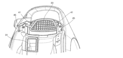
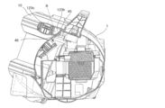
図13は、掃除機本体の排気口33を示す集塵装置10を取り外した状態の斜視図、図14は、集塵装置10と装着した状態での第4の実施形態の構成を説明するための部分断面図、図15の円で示した破線部分の拡大断面図である。
図6、また図13に示すように、掃除機本体1側には、係止凹部41とは別に、それよりも下部に突出するように一対の固定片45が設けられている。この固定片45に対し、図4に示すように集塵装置10側のカバー本体123cに一体に形成されている下方開口端縁123hの外面と、上部カバー本体123cの内面との間を連結するように設けられた固定片45と係止する一対の規制部材46が一体に設けられている。この規制部材46の上面は凹部形状となっている。規制部材46は、図15の拡大図に示すように固定片45の下部に当接するように形成されている。
以上の構成により、集塵装置10が装着された状態で、係止爪123lが係止凹部41に係止されると同時に、集塵装置10のカバー本体123cに形成された規制部材46の上面が掃除機本体1側に設けられた固定片45と当接する。これにより、集塵装置10の上方向への押し上げが規制される。
集塵装置10は掃除機本体1に対し装着される場合、載置台20に集塵装置10の底面、特に底蓋114の部分を載置する。集塵装置10は掃除機本体1に対して、先に説明したように約20°程度電動送風機30側へ傾斜配置されるため、載置された集塵装置10を掃除機本体1側へと倒す。このとき、掃除機本体1側の固定片45に規制部材46が回転するようにして固定片45の下面へと挿入されるため、その操作が非常にスムースに行なえる。それを助長するためにも、図15に示すように、固定片45の突出端部の下面に傾斜面45aが形成されている。
したがって、圧縮部127を駆動し、塵埃を圧縮し、その圧縮率が非常に高まっても、集塵装置10の位置づけが変化し、変位するのを防止できる。
本発明は、電機掃除機において、集塵装置としてサイクロン集塵装置を備えた事例を説明したが、このようなサイクロン式の集塵装置だけでなく、空気中の塵埃を分離し、分離された塵埃を集塵し、分離後の空気をさらにフィルタを介しての細かな塵埃を除去するようにした電気掃除機全般に利用することができる。
A 電気掃除機
1 掃除機本体
2 吸込口部
3 接続管
4 接続ホース
5 操作ハンドル
10 サイクロン集塵装置(集塵装置)
11 集塵カップ
111 集塵容器
113 底蓋(底部)
114
12 フィルタユニット
121 排気側フィルタ(フィルタ)
122 フィルタケース
123 フィルタカバー
123c カバー本体
123d ハンドル部
124 内筒部
125 フィルタの除塵機構
126 第2の除塵機構
20 載置台
21 凹部
22 第2凹部
24 傾斜面
45
50 第1の回転伝達機構
52 伝達ギア(伝達部)
55 連結部
60 第2の回転伝達機構
61 連結部
62 第1連結円筒
62a 係止片
63 第2連結円筒
64 連結片
70 駆動部
71 駆動モータ(駆動力発生源)
72 駆動ギア
73 第1減速ギア
74 第2減速ギア
75 伝達駆動ギア(伝達駆動部)
1 掃除機本体
2 吸込口部
3 接続管
4 接続ホース
5 操作ハンドル
10 サイクロン集塵装置(集塵装置)
11 集塵カップ
111 集塵容器
113 底蓋(底部)
114
12 フィルタユニット
121 排気側フィルタ(フィルタ)
122 フィルタケース
123 フィルタカバー
123c カバー本体
123d ハンドル部
124 内筒部
125 フィルタの除塵機構
126 第2の除塵機構
20 載置台
21 凹部
22 第2凹部
24 傾斜面
45
50 第1の回転伝達機構
52 伝達ギア(伝達部)
55 連結部
60 第2の回転伝達機構
61 連結部
62 第1連結円筒
62a 係止片
63 第2連結円筒
64 連結片
70 駆動部
71 駆動モータ(駆動力発生源)
72 駆動ギア
73 第1減速ギア
74 第2減速ギア
75 伝達駆動ギア(伝達駆動部)
Claims (5)
- 空気に含まれる塵埃から分離された塵埃を集塵する集塵容器を備える集塵装置であって、
前記集塵装置は、
前記集塵容器の上部に設けられ分離後の空気を排気する排気フィルタ、
排気フィルタの上部に設けられ、該排気フィルタを振動させるフィルタ除塵機構、
前記集塵容器の底部に設けられ駆動部と連結され、駆動部の駆動力が伝わる伝達部、
前記伝達部の駆動力を前記フィルタ除塵機構に伝達する伝達機構、を備えた集塵装置。 - 前記集塵容器は、
吸引された空気を集塵容器へと導入しサイクロン分離する分離部を有し、
前記サイクロン分離された塵埃を底部に集塵する開閉可能な底蓋を備えてなり、
前記底蓋の下面に、駆動部と連結される伝達部を設けた請求項1記載の集塵装置。 - 請求項1または2に記載の集塵装置は、
塵埃を含む空気を吸引する掃除機本体に着脱可能に設けられ、
掃除機本体は、前記集塵装置の底部を載置してなる載置台を設け、
前記載置台には、前記集塵装置の伝達部に対応する部分を凹ました凹部、該凹部に前記伝達部に駆動力を伝える掃除機本体に設けられた駆動部の伝達駆動部を設けた、電気掃除機。 - 前記載置台には、前記凹部の外周部に第2の凹部が設けられ、
前記集塵掃除に底部には、前記第2の凹部に対応して下部への突出する突出部を設け、
前記突出部の一部が前記伝達部よりも突出してなる請求項3記載の電気掃除機。 - 前記集塵装置は、集塵した塵埃を圧縮する圧縮部を備え、
前記圧縮部は、前記伝達機構の駆動力が伝達され、集塵した塵埃を圧縮し、
前記掃除機本体側に集塵装置内の塵埃が圧縮されることで上方への上昇を規制する固定片を設け、
前記集塵装置側には、前記固定片と当接する規制部材を設け、該規制部材にて集塵装置の上昇を規制することを特徴とする請求項3または4に記載の電気掃除機。
Priority Applications (1)
| Application Number | Priority Date | Filing Date | Title |
|---|---|---|---|
| CN201490000995.5U CN205585957U (zh) | 2013-09-05 | 2014-02-24 | 集尘装置和电动吸尘器 |
Applications Claiming Priority (2)
| Application Number | Priority Date | Filing Date | Title |
|---|---|---|---|
| JP2013183731A JP2015051032A (ja) | 2013-09-05 | 2013-09-05 | 集塵装置および電気掃除機 |
| JP2013-183731 | 2013-09-05 |
Publications (1)
| Publication Number | Publication Date |
|---|---|
| WO2015033592A1 true WO2015033592A1 (ja) | 2015-03-12 |
Family
ID=52628087
Family Applications (1)
| Application Number | Title | Priority Date | Filing Date |
|---|---|---|---|
| PCT/JP2014/054338 Ceased WO2015033592A1 (ja) | 2013-09-05 | 2014-02-24 | 集塵装置および電気掃除機 |
Country Status (3)
| Country | Link |
|---|---|
| JP (1) | JP2015051032A (ja) |
| CN (1) | CN205585957U (ja) |
| WO (1) | WO2015033592A1 (ja) |
Cited By (1)
| Publication number | Priority date | Publication date | Assignee | Title |
|---|---|---|---|---|
| DE102015106289A1 (de) * | 2015-04-23 | 2016-10-27 | Miele & Cie. Kg | Staubsauger sowie Filtereinheit zur Verwendung mit einem Staubsauger |
Families Citing this family (6)
| Publication number | Priority date | Publication date | Assignee | Title |
|---|---|---|---|---|
| CN206924038U (zh) * | 2016-12-01 | 2018-01-26 | 天佑电器(苏州)有限公司 | 吸尘器 |
| JP6886834B2 (ja) * | 2017-02-17 | 2021-06-16 | 株式会社マキタ | 集塵機 |
| CN107468159B (zh) * | 2017-10-10 | 2023-09-12 | 小狗电器互联网科技(北京)股份有限公司 | 吸尘组件及吸尘器 |
| JP2019122659A (ja) * | 2018-01-18 | 2019-07-25 | シャープ株式会社 | 電気掃除機 |
| CN112021996B (zh) * | 2019-06-04 | 2022-07-01 | 康塔有限公司 | 旋风分离器 |
| CN119279432A (zh) * | 2019-12-27 | 2025-01-10 | 爱丽思欧雅玛株式会社 | 电动吸尘器单元 |
Citations (3)
| Publication number | Priority date | Publication date | Assignee | Title |
|---|---|---|---|---|
| JP2007125294A (ja) * | 2005-11-07 | 2007-05-24 | Sharp Corp | 集塵器およびそれを備えた電気掃除機 |
| JP2012065877A (ja) * | 2010-09-24 | 2012-04-05 | Sharp Corp | 電気掃除機 |
| JP2012135514A (ja) * | 2010-12-27 | 2012-07-19 | Toshiba Corp | 電気掃除機 |
-
2013
- 2013-09-05 JP JP2013183731A patent/JP2015051032A/ja active Pending
-
2014
- 2014-02-24 WO PCT/JP2014/054338 patent/WO2015033592A1/ja not_active Ceased
- 2014-02-24 CN CN201490000995.5U patent/CN205585957U/zh not_active Expired - Fee Related
Patent Citations (3)
| Publication number | Priority date | Publication date | Assignee | Title |
|---|---|---|---|---|
| JP2007125294A (ja) * | 2005-11-07 | 2007-05-24 | Sharp Corp | 集塵器およびそれを備えた電気掃除機 |
| JP2012065877A (ja) * | 2010-09-24 | 2012-04-05 | Sharp Corp | 電気掃除機 |
| JP2012135514A (ja) * | 2010-12-27 | 2012-07-19 | Toshiba Corp | 電気掃除機 |
Cited By (1)
| Publication number | Priority date | Publication date | Assignee | Title |
|---|---|---|---|---|
| DE102015106289A1 (de) * | 2015-04-23 | 2016-10-27 | Miele & Cie. Kg | Staubsauger sowie Filtereinheit zur Verwendung mit einem Staubsauger |
Also Published As
| Publication number | Publication date |
|---|---|
| CN205585957U (zh) | 2016-09-21 |
| JP2015051032A (ja) | 2015-03-19 |
Similar Documents
| Publication | Publication Date | Title |
|---|---|---|
| WO2015033592A1 (ja) | 集塵装置および電気掃除機 | |
| CN105530847B (zh) | 集尘装置和电动吸尘器 | |
| CN110662471B (zh) | 电动吸尘装置 | |
| JP2003000497A5 (ja) | ||
| CN110573048A (zh) | 电动吸尘装置 | |
| TWI576081B (zh) | vacuum cleaner | |
| CN110573052A (zh) | 电动吸尘装置 | |
| JP2011092472A (ja) | 電気掃除機 | |
| JP2014076141A (ja) | 電気掃除機 | |
| JP2010104502A (ja) | 電気掃除機 | |
| JP2013183760A (ja) | 電気掃除機 | |
| JP6703386B2 (ja) | 電気掃除機 | |
| JP5416549B2 (ja) | 電気掃除機 | |
| JP6140580B2 (ja) | 集塵装置 | |
| JP2020005755A (ja) | 電気掃除機 | |
| CN110049704A (zh) | 电动吸尘器 | |
| JP6334204B2 (ja) | 集塵装置、及び電気掃除機 | |
| JP2017023289A (ja) | 電気掃除機 | |
| CN110099598A (zh) | 电动吸尘器 | |
| JP2021194470A (ja) | 電気掃除機の集塵装置およびそれを備えた電気掃除機 | |
| JP7169904B2 (ja) | 電気掃除機 | |
| JP6254436B2 (ja) | 電気掃除機 | |
| JP2018140240A (ja) | 集塵装置、及び電気掃除機 | |
| JP2015163144A (ja) | 集塵装置、及び電気掃除機 | |
| JP2008279201A (ja) | 電気掃除機 |
Legal Events
| Date | Code | Title | Description |
|---|---|---|---|
| 121 | Ep: the epo has been informed by wipo that ep was designated in this application |
Ref document number: 14842343 Country of ref document: EP Kind code of ref document: A1 |
|
| NENP | Non-entry into the national phase |
Ref country code: DE |
|
| 122 | Ep: pct application non-entry in european phase |
Ref document number: 14842343 Country of ref document: EP Kind code of ref document: A1 |