WO2015029633A1 - 液晶表示装置および液晶表示装置における画像表示方法 - Google Patents
液晶表示装置および液晶表示装置における画像表示方法 Download PDFInfo
- Publication number
- WO2015029633A1 WO2015029633A1 PCT/JP2014/068986 JP2014068986W WO2015029633A1 WO 2015029633 A1 WO2015029633 A1 WO 2015029633A1 JP 2014068986 W JP2014068986 W JP 2014068986W WO 2015029633 A1 WO2015029633 A1 WO 2015029633A1
- Authority
- WO
- WIPO (PCT)
- Prior art keywords
- liquid crystal
- color gamut
- color
- crystal panel
- input signal
- Prior art date
- Legal status (The legal status is an assumption and is not a legal conclusion. Google has not performed a legal analysis and makes no representation as to the accuracy of the status listed.)
- Ceased
Links
Images




Classifications
-
- G—PHYSICS
- G09—EDUCATION; CRYPTOGRAPHY; DISPLAY; ADVERTISING; SEALS
- G09G—ARRANGEMENTS OR CIRCUITS FOR CONTROL OF INDICATING DEVICES USING STATIC MEANS TO PRESENT VARIABLE INFORMATION
- G09G3/00—Control arrangements or circuits, of interest only in connection with visual indicators other than cathode-ray tubes
- G09G3/20—Control arrangements or circuits, of interest only in connection with visual indicators other than cathode-ray tubes for presentation of an assembly of a number of characters, e.g. a page, by composing the assembly by combination of individual elements arranged in a matrix no fixed position being assigned to or needed to be assigned to the individual characters or partial characters
- G09G3/2003—Display of colours
-
- G—PHYSICS
- G09—EDUCATION; CRYPTOGRAPHY; DISPLAY; ADVERTISING; SEALS
- G09G—ARRANGEMENTS OR CIRCUITS FOR CONTROL OF INDICATING DEVICES USING STATIC MEANS TO PRESENT VARIABLE INFORMATION
- G09G5/00—Control arrangements or circuits for visual indicators common to cathode-ray tube indicators and other visual indicators
- G09G5/02—Control arrangements or circuits for visual indicators common to cathode-ray tube indicators and other visual indicators characterised by the way in which colour is displayed
-
- G—PHYSICS
- G09—EDUCATION; CRYPTOGRAPHY; DISPLAY; ADVERTISING; SEALS
- G09G—ARRANGEMENTS OR CIRCUITS FOR CONTROL OF INDICATING DEVICES USING STATIC MEANS TO PRESENT VARIABLE INFORMATION
- G09G3/00—Control arrangements or circuits, of interest only in connection with visual indicators other than cathode-ray tubes
- G09G3/20—Control arrangements or circuits, of interest only in connection with visual indicators other than cathode-ray tubes for presentation of an assembly of a number of characters, e.g. a page, by composing the assembly by combination of individual elements arranged in a matrix no fixed position being assigned to or needed to be assigned to the individual characters or partial characters
- G09G3/34—Control arrangements or circuits, of interest only in connection with visual indicators other than cathode-ray tubes for presentation of an assembly of a number of characters, e.g. a page, by composing the assembly by combination of individual elements arranged in a matrix no fixed position being assigned to or needed to be assigned to the individual characters or partial characters by control of light from an independent source
- G09G3/36—Control arrangements or circuits, of interest only in connection with visual indicators other than cathode-ray tubes for presentation of an assembly of a number of characters, e.g. a page, by composing the assembly by combination of individual elements arranged in a matrix no fixed position being assigned to or needed to be assigned to the individual characters or partial characters by control of light from an independent source using liquid crystals
-
- G—PHYSICS
- G09—EDUCATION; CRYPTOGRAPHY; DISPLAY; ADVERTISING; SEALS
- G09G—ARRANGEMENTS OR CIRCUITS FOR CONTROL OF INDICATING DEVICES USING STATIC MEANS TO PRESENT VARIABLE INFORMATION
- G09G3/00—Control arrangements or circuits, of interest only in connection with visual indicators other than cathode-ray tubes
- G09G3/20—Control arrangements or circuits, of interest only in connection with visual indicators other than cathode-ray tubes for presentation of an assembly of a number of characters, e.g. a page, by composing the assembly by combination of individual elements arranged in a matrix no fixed position being assigned to or needed to be assigned to the individual characters or partial characters
- G09G3/34—Control arrangements or circuits, of interest only in connection with visual indicators other than cathode-ray tubes for presentation of an assembly of a number of characters, e.g. a page, by composing the assembly by combination of individual elements arranged in a matrix no fixed position being assigned to or needed to be assigned to the individual characters or partial characters by control of light from an independent source
- G09G3/36—Control arrangements or circuits, of interest only in connection with visual indicators other than cathode-ray tubes for presentation of an assembly of a number of characters, e.g. a page, by composing the assembly by combination of individual elements arranged in a matrix no fixed position being assigned to or needed to be assigned to the individual characters or partial characters by control of light from an independent source using liquid crystals
- G09G3/3607—Control arrangements or circuits, of interest only in connection with visual indicators other than cathode-ray tubes for presentation of an assembly of a number of characters, e.g. a page, by composing the assembly by combination of individual elements arranged in a matrix no fixed position being assigned to or needed to be assigned to the individual characters or partial characters by control of light from an independent source using liquid crystals for displaying colours or for displaying grey scales with a specific pixel layout, e.g. using sub-pixels
-
- H—ELECTRICITY
- H04—ELECTRIC COMMUNICATION TECHNIQUE
- H04N—PICTORIAL COMMUNICATION, e.g. TELEVISION
- H04N1/00—Scanning, transmission or reproduction of documents or the like, e.g. facsimile transmission; Details thereof
- H04N1/46—Colour picture communication systems
- H04N1/56—Processing of colour picture signals
- H04N1/60—Colour correction or control
- H04N1/6058—Reduction of colour to a range of reproducible colours, e.g. to ink- reproducible colour gamut
-
- G—PHYSICS
- G09—EDUCATION; CRYPTOGRAPHY; DISPLAY; ADVERTISING; SEALS
- G09G—ARRANGEMENTS OR CIRCUITS FOR CONTROL OF INDICATING DEVICES USING STATIC MEANS TO PRESENT VARIABLE INFORMATION
- G09G2320/00—Control of display operating conditions
- G09G2320/02—Improving the quality of display appearance
- G09G2320/0233—Improving the luminance or brightness uniformity across the screen
-
- G—PHYSICS
- G09—EDUCATION; CRYPTOGRAPHY; DISPLAY; ADVERTISING; SEALS
- G09G—ARRANGEMENTS OR CIRCUITS FOR CONTROL OF INDICATING DEVICES USING STATIC MEANS TO PRESENT VARIABLE INFORMATION
- G09G2320/00—Control of display operating conditions
- G09G2320/02—Improving the quality of display appearance
- G09G2320/0242—Compensation of deficiencies in the appearance of colours
-
- G—PHYSICS
- G09—EDUCATION; CRYPTOGRAPHY; DISPLAY; ADVERTISING; SEALS
- G09G—ARRANGEMENTS OR CIRCUITS FOR CONTROL OF INDICATING DEVICES USING STATIC MEANS TO PRESENT VARIABLE INFORMATION
- G09G2320/00—Control of display operating conditions
- G09G2320/02—Improving the quality of display appearance
- G09G2320/0271—Adjustment of the gradation levels within the range of the gradation scale, e.g. by redistribution or clipping
- G09G2320/0276—Adjustment of the gradation levels within the range of the gradation scale, e.g. by redistribution or clipping for the purpose of adaptation to the characteristics of a display device, i.e. gamma correction
-
- G—PHYSICS
- G09—EDUCATION; CRYPTOGRAPHY; DISPLAY; ADVERTISING; SEALS
- G09G—ARRANGEMENTS OR CIRCUITS FOR CONTROL OF INDICATING DEVICES USING STATIC MEANS TO PRESENT VARIABLE INFORMATION
- G09G2320/00—Control of display operating conditions
- G09G2320/06—Adjustment of display parameters
- G09G2320/0666—Adjustment of display parameters for control of colour parameters, e.g. colour temperature
-
- G—PHYSICS
- G09—EDUCATION; CRYPTOGRAPHY; DISPLAY; ADVERTISING; SEALS
- G09G—ARRANGEMENTS OR CIRCUITS FOR CONTROL OF INDICATING DEVICES USING STATIC MEANS TO PRESENT VARIABLE INFORMATION
- G09G2320/00—Control of display operating conditions
- G09G2320/06—Adjustment of display parameters
- G09G2320/0673—Adjustment of display parameters for control of gamma adjustment, e.g. selecting another gamma curve
-
- G—PHYSICS
- G09—EDUCATION; CRYPTOGRAPHY; DISPLAY; ADVERTISING; SEALS
- G09G—ARRANGEMENTS OR CIRCUITS FOR CONTROL OF INDICATING DEVICES USING STATIC MEANS TO PRESENT VARIABLE INFORMATION
- G09G2340/00—Aspects of display data processing
- G09G2340/06—Colour space transformation
Definitions
- the present invention relates to a liquid crystal display device and an image display method in the liquid crystal display device, and more particularly to a color reproduction technique using color gamut conversion processing in a liquid crystal display device.
- the resolution of display devices such as liquid crystal display devices has been increasing. Further, the improvement of the color reproduction capability of the display device is also remarkable.
- the NTSC ratio is adopted as an index representing the color reproduction capability of the display device, and a liquid crystal display device having an NTSC ratio of about 150% is also realized.
- display devices, printing devices, imaging devices, and the like have different color gamuts (also referred to as “color reproduction ranges”) for each model. Further, for example, in a color television apparatus, the color gamut of the input video signal is different for each adopted television system. For this reason, it has been proposed to perform various conversion processes on input data so that a color as faithful as possible to the input data is output regardless of the difference in color gamut.
- an input signal is displayed so that a color as faithful as possible to the input signal is displayed regardless of the difference between the color gamut of an image output device such as a display device and the color gamut of the input signal to the image output device.
- the process of correcting the value is called “color gamut conversion process”.
- Japanese Patent Application Laid-Open No. 2004-110647 discloses an invention relating to a color conversion coefficient creation method in which a color conversion coefficient can be determined so as not to cause color skip or fading in a color management system.
- Japanese Patent Laid-Open No. 2003-134351 discloses an invention relating to a spectrum / color reproduction system that performs color conversion processing using an input profile, a display profile, a color space conversion profile, and the like.
- the following two points can be cited as reasons why the color perceived by the purchaser of the product through the screen at the time of ordering differs from the color of the actual product.
- the first point is that conventional display devices have low color reproducibility, so in image and video processing with digital cameras and television devices, emphasis is placed on making the subject look better than faithfully reproducing the subject's color. It is that it was done.
- the second point is that the color gamut of the display content exceeds the display capability (color reproduction capability) of the display device. This will be described with reference to FIG.
- FIG. 14 is an xy chromaticity diagram of CIE1931. In FIG.
- the color range that can be seen by the human eye is represented by a dotted line 91
- the color gamut in the NTSC standard is represented by a bold line 92
- the color gamut in the sRGB standard is represented by a solid line 93.
- the color gamut in the NTSC standard is represented by triangles with apexes a1, b1, and c1.
- the color gamut in the sRGB standard is represented by a triangle having apexes a2, b2, and c2.
- the NTSC ratio of the sRGB standard is 71%.
- the color gamut in the NTSC standard is larger than the color gamut in the sRGB standard.
- a display device having the same color gamut as the NTSC standard conforms to the sRGB standard as an input signal. When a signal is given, the original color based on the input signal cannot be completely reproduced.
- the color conversion coefficient creating method described in Japanese Unexamined Patent Application Publication No. 2004-110647 if there is color data that exceeds the color gamut of the display device, the color data is included in the color gamut of the display device. Is subjected to linear compression. In other words, the color is merely displayed so as not to give a sense of incongruity to the person, and the color is not reproduced faithfully. Further, even with the spectrum / color reproduction system described in Japanese Patent Application Laid-Open No. 2003-134351, colors are not completely reproduced faithfully.
- an object of the present invention is to provide a liquid crystal display device capable of faithfully reproducing colors. Another object of the present invention is to provide a liquid crystal display device capable of showing information to the user as to whether or not the color is faithfully reproduced so as not to mislead the user about the displayed color. And
- a first aspect of the present invention is a liquid crystal display device having a liquid crystal panel for displaying a color image based on an input signal, Color gamut conversion for generating a display image signal to be given to the liquid crystal panel by converting the data value of each color included in the input signal based on the color gamut of the input signal and the color gamut of the liquid crystal panel Part
- the display image signal generated by the color gamut conversion unit is supplied to the liquid crystal panel, whereby the color represented by the input signal Is faithfully reproduced on the liquid crystal panel.
- a color gamut determination unit that determines whether or not the color gamut of the input signal is included in the color gamut of the liquid crystal panel and gives a determination signal indicating the determination result to the liquid crystal panel;
- the liquid crystal panel displays information indicating whether or not the color represented by the input signal is faithfully reproduced based on the determination signal.
- the color gamut determination unit includes all of the chromaticity coordinates of the three primary colors specifying the color gamut of the input signal within a triangle representing the color gamut of the liquid crystal panel, the color gamut of the input signal is It is determined that it is included in the color gamut of the liquid crystal panel.
- the color gamut determination unit includes: If the line connecting the coordinates existing inside the panel color gamut triangle and the primary color chromaticity coordinates does not intersect any of the three line segments constituting the panel color gamut triangle, the primary color chromaticity coordinates are It is characterized in that it is determined that it is contained within the panel color gamut triangle.
- the color gamut determination unit is a line connecting the coordinates specified by the average value of x coordinates and the average value of y coordinates for the chromaticity coordinates of the three primary colors specifying the color gamut of the liquid crystal panel and the primary color chromaticity coordinates. If the minute does not intersect with any of the three line segments constituting the panel color gamut triangle, it is determined that the primary color chromaticity coordinates are included in the panel color gamut triangle. To do.
- a coefficient calculation unit for calculating a conversion coefficient to be used by the color gamut conversion unit.
- a seventh aspect of the present invention is the sixth aspect of the present invention
- the input signal and the display image signal are RGB color system data
- the relationship between the input signal and the display image signal is expressed by the following equation (A), where T is the conversion coefficient.
- the coefficient calculation unit converts an RGB value, which is a tristimulus value of the input signal, into an XYZ value, which is a tristimulus value of data in the XYZ color system, according to the color gamut of the input signal ( B) and the following formula for converting RGB values, which are tristimulus values of the display image signal, into XYZ values, which are tristimulus values of XYZ color system data, according to the color gamut of the liquid crystal panel: C), the conversion coefficient T is obtained by the following equation (D).
- the image processing apparatus further includes a gamma correction processing unit that performs gamma correction processing on the display image signal.
- a ninth aspect of the present invention is the eighth aspect of the present invention, A degamma correction processing unit that performs degamma correction processing on the input signal is further provided.
- a conversion coefficient holding unit for holding in advance for each type of the input signal a conversion coefficient to be used by the color gamut conversion unit when converting the data value of each color included in the input signal;
- the color gamut conversion unit converts a data value of each color included in the input signal using a conversion coefficient held in the conversion coefficient holding unit according to a type of the input signal.
- a display mode selection unit for externally selecting one of a plurality of display modes including a faithful display mode for faithfully reproducing the color represented by the input signal on the liquid crystal panel;
- the display mode selection unit When the faithful display mode is selected by the display mode selection unit, the display image signal generated by the color gamut conversion unit is supplied to the liquid crystal panel.
- a twelfth aspect of the present invention is the eleventh aspect of the present invention, If the color gamut of the input signal is not completely included in the color gamut of the liquid crystal panel even though the faithful display mode is selected by the display mode selection unit, the color represented by the input signal is faithful. Is displayed on the liquid crystal panel, indicating that the information is not reproduced.
- a thirteenth aspect of the present invention is the eleventh aspect of the present invention, Only when the faithful display mode is selected by the display mode selection unit, information indicating whether or not the color represented by the input signal is faithfully reproduced is displayed on the liquid crystal panel. .
- the color gamut of the liquid crystal panel includes the color gamut of the sRGB standard.
- a fifteenth aspect of the present invention is an image display method in a liquid crystal display device having a liquid crystal panel for displaying a color image based on an input signal, Color gamut conversion for generating a display image signal to be given to the liquid crystal panel by converting the data value of each color included in the input signal based on the color gamut of the input signal and the color gamut of the liquid crystal panel Steps, Displaying the color image on the liquid crystal panel, In the display step, as long as the color gamut of the input signal is included in the color gamut of the liquid crystal panel, the display image signal generated in the color gamut conversion step is given to the liquid crystal panel, The color represented by the input signal is faithfully reproduced on the liquid crystal panel.
- a color gamut conversion unit that converts the data value of each color included in the input signal based on the color gamut of the input signal and the color gamut of the liquid crystal panel. Therefore, as long as the color gamut of the input signal is included in the color gamut of the liquid crystal panel, the color represented by the input signal can be faithfully reproduced on the liquid crystal panel.
- the user can recognize whether or not the color is faithfully reproduced. For this reason, it is possible to prevent the user from misunderstanding the colors displayed on the liquid crystal panel. Thus, for example, when online shopping is performed, occurrence of troubles caused by the difference between the color perceived by the purchaser of the product through the screen and the color of the actual product is prevented.
- the third aspect of the present invention it is possible to reliably determine whether or not the color represented by the input signal can be faithfully reproduced on the liquid crystal panel.
- the fourth aspect of the present invention as in the third aspect of the present invention, it is possible to reliably determine whether or not the color represented by the input signal can be faithfully reproduced on the liquid crystal panel. .
- the fifth aspect of the present invention as in the third aspect of the present invention, it is possible to reliably determine whether or not the color represented by the input signal can be faithfully reproduced on the liquid crystal panel. .
- a conversion coefficient for color gamut conversion processing is calculated according to the color gamut of the input signal. For this reason, as long as the color gamut of the input signal is included in the color gamut of the liquid crystal panel, colors can be faithfully reproduced on the liquid crystal panel based on the input signal having an arbitrary color gamut.
- the conversion coefficient for the color gamut conversion process is calculated based on a predetermined formula in consideration of the color gamut of the input signal and the color gamut of the liquid crystal panel. Therefore, as long as the color gamut of the input signal is included in the color gamut of the liquid crystal panel, the color represented by the input signal can be reliably reproduced on the liquid crystal panel.
- the liquid crystal panel has a non-linear characteristic regarding the relationship between the gradation level of the display image signal (input signal to the liquid crystal panel) and the display luminance.
- the input signal is a signal that has been subjected to gamma correction processing, and the relationship between the gradation level of the display image signal (input signal to the liquid crystal panel) and the display luminance Even when the liquid crystal panel has a non-linear characteristic, the degamma correction processing is performed on the input signal and the gamma correction processing is performed on the display image signal. The same effect as in the first aspect can be obtained.
- the liquid crystal display device is provided with a color gamut conversion unit for holding a conversion coefficient for color gamut conversion processing. For this reason, it is not necessary to provide the component for calculating a conversion coefficient in a liquid crystal display device. Therefore, a liquid crystal display device capable of faithfully reproducing colors can be realized at low cost.
- the user can select whether or not to reproduce the color faithfully.
- the user is prevented from misinterpreting the color displayed on the liquid crystal panel.
- the fourteenth aspect of the present invention as long as the input signal conforms to the sRGB standard, the color represented by the input signal can be faithfully reproduced on the liquid crystal panel.
- the same effect as in the first aspect of the present invention can be achieved in the image display method in the liquid crystal display device.
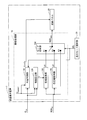
- FIG. 1 is a block diagram illustrating an overall configuration of a liquid crystal display device according to a first embodiment of the present invention.
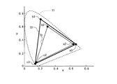
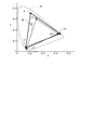
- it is an xy chromaticity diagram for demonstrating the relationship between the color gamut of a liquid crystal panel, and the color gamut in sRGB specification.
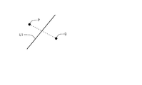
- FIG. 6 is a diagram for describing color gamut determination processing in the first embodiment.
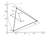
- it is xy chromaticity diagram for demonstrating a color gamut discrimination
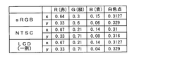
- FIG. 4 is a diagram illustrating chromaticity coordinates of three primary colors and a white point for each of an sRGB standard color gamut, an NTSC standard color gamut, and a liquid crystal panel color gamut (one example) in the first embodiment.
- it is a figure for demonstrating the notation of a matrix.
- it is a figure for demonstrating the notation of a matrix.
- it is a figure for demonstrating the flow of a color gamut conversion process.
- it is a figure which shows an example of the display of the character information to the effect that the color is reproduced faithfully.
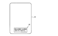
- the said 1st Embodiment it is a figure which shows an example of the display of the character information that the color is not reproduced faithfully. It is a figure for demonstrating the flow of the color gamut conversion process in the 2nd Embodiment of this invention. It is a figure for demonstrating the flow of the color gamut conversion process in the modification of the said 2nd Embodiment. It is a block diagram which shows the whole structure of the liquid crystal display device which concerns on the 3rd Embodiment of this invention. In a conventional example, it is an xy chromaticity diagram for demonstrating the relationship between the color gamut of sRGB standard, and the color gamut of NTSC standard.
- FIG. 1 is a block diagram showing an overall configuration of a liquid crystal display device 1 according to the first embodiment of the present invention.
- the liquid crystal display device 1 includes an image processing unit 10, a liquid crystal panel 20, and a display mode selection unit 30.
- the display mode selection unit 30 may be provided outside the liquid crystal display device 1.
- the image processing unit 10 receives an input RGB signal RGB in (input signal) given from the outside, and outputs an RGB signal RGB out (display image signal) for a liquid crystal panel. That is, the image processing unit 10 performs a process of converting the input RGB signal RGB in to the liquid crystal panel RGB signal RGB out .
- the conversion is performed based on the chromaticity coordinates C in of the three primary colors in the standard of the input RGB signal RGB in and the display mode selection signal SEL given from the display mode selection unit 30.
- the image processing unit 10 gives a character information signal Sinfo described later to the liquid crystal panel 20.
- the display mode selection unit 30 receives the selection of the display mode by the user, and provides the image processing unit 10 with a display mode selection signal SEL indicating the display mode selected by the user.
- the liquid crystal panel 20 receives the RGB signal RGB out for the liquid crystal panel output from the image processing unit 10 and displays a color image based on the RGB signal RGB out for the liquid crystal panel.
- the liquid crystal panel 20 receives the character information signal Sinfo output from the image processing unit 10 and displays character information based on the character information signal Sinfo.
- the determination signal is realized by the character information signal Sinfo.
- FIG. 2 is an xy chromaticity diagram for explaining the relationship between the color gamut of the liquid crystal panel 20 and the color gamut according to the sRGB standard in the present embodiment.
- the color range that can be seen by the human eye is represented by a curve 71
- the color gamut of the liquid crystal panel 20 in this embodiment is a triangle 72 (the triangles having apexes a3, b3, and c3).
- the color gamut in the sRGB standard is represented by a triangle 73 (a triangle having apexes a2, b2, and c2). As shown in FIG.
- the vertices a2, b2, and c2 of the triangle representing the color gamut in the sRGB standard are all included in the triangle representing the color gamut of the liquid crystal panel 20. That is, the color gamut of the liquid crystal panel 20 in the present embodiment completely includes the color gamut of the sRGB standard. Therefore, if the input RGB signal RGB in is a signal conforming to the sRGB standard, the liquid crystal panel 20 in the present embodiment can faithfully reproduce the color represented by the input RGB signal RGB in .
- the image processing unit 10 includes a color gamut determination unit 110, a coefficient calculation unit 120, a color gamut conversion unit 130, a color compression processing unit 140, and a mode switching unit 150.
- Color gamut determination portion 110 based on the chromaticity coordinates C panel of three primary colors in the input RGB signal RGB in three primary chromaticity coordinates C in the liquid crystal panel 20 of the standard, the color gamut of the input RGB signal RGB in the It is determined whether or not it is completely included in the color gamut of the liquid crystal panel 20. In other words, the color gamut determination unit 110 determines whether or not the liquid crystal panel 20 can faithfully reproduce a color based on the input RGB signal RGB in . In the following, this process performed by the color gamut determination unit 110 is referred to as “color gamut determination process”.
- the color gamut determination unit 110 provides the character information signal Sinfo to the liquid crystal panel 20 based on the determination result and the display mode selection signal SEL provided from the display mode selection unit 30. Specifically, the determination result that the display mode selection signal SEL indicates a “faithful display mode” to be described later, and “the color gamut of the input RGB signal RGB in is completely included in the color gamut of the liquid crystal panel 20”. Is obtained, the color gamut determination unit 110 gives the liquid crystal panel 20 a character information signal Sinfo for displaying character information indicating that the color is faithfully reproduced.
- the color gamut determination unit 110 gives the liquid crystal panel 20 a character information signal Sinfo for displaying character information indicating that the color is not faithfully displayed.
- the display mode selection signal SEL indicates a display mode other than the “faithful display mode”
- the character information signal Sinfo for instructing not to display the character information as described above is given to the liquid crystal panel 20.
- Coefficient calculation unit 120 based on the chromaticity coordinates C in the three primary colors in the standard of the input RGB signal RGB in the chromaticity coordinates C panel of three primary colors in the liquid crystal panel 20, the color gamut is performed by the gamut conversion unit 130 A conversion coefficient T for use in the conversion process is calculated. A detailed description of the color gamut conversion process and the calculation of the conversion coefficient T will be described later.
- the color gamut conversion unit 130 performs color gamut conversion processing on the input RGB signal RGB in using the conversion coefficient T calculated by the coefficient calculation unit 120.
- the color compression processing unit 140 displays the input RGB signal RGB in so that a color that does not give a strange feeling to a person when the color gamut of the input RGB signal RGB in is larger than the color gamut of the liquid crystal panel 20 is displayed. A process for compressing the gradation value is performed.
- the signal output from the color gamut conversion unit 130 is referred to as an internal signal d1
- the signal output from the color compression processing unit 140 is referred to as an internal signal d
- the mode switching unit 150 switches the signal given to the liquid crystal panel 20 as the RGB signal RGB out for the liquid crystal panel according to the display mode selection signal SEL given from the display mode selection unit 30.
- three display modes of “faithful display mode”, “color compression display mode”, and “through display mode” are provided.
- Faithful display mode is a mode for faithfully reproducing colors expressed by the input RGB signal RGB in.
- the color compression display mode is a mode for displaying a color that does not make the person feel as uncomfortable as possible.
- the through display mode is a mode for performing display by using the gradation value of the input RGB signal RGB in as it is as the gradation value of the RGB signal RGB out for the liquid crystal panel. According to the through display mode, when the color gamut of the liquid crystal panel 20 is larger than the color gamut of the input RGB signal RGB in , the display fully utilizes the color reproduction capability of the liquid crystal panel 20 (for example, flashy display). Can be performed.
- the mode switching unit 150 When the display mode selection signal SEL indicates the “faithful display mode”, the mode switching unit 150 is in a state where the point K and the point K1 are connected. Thereby, the internal signal d1 output from the color gamut conversion unit 130 is given to the liquid crystal panel 20 as the RGB signal RGB out for the liquid crystal panel.
- the display mode selection signal SEL indicates “color compression display mode”
- the mode switching unit 150 is in a state where the point K and the point K2 are connected. Accordingly, the internal signal d2 output from the color compression processing unit 140 is given to the liquid crystal panel 20 as the RGB signal RGB out for the liquid crystal panel.
- the display mode selection signal SEL indicates “through display mode”
- the mode switching unit 150 is in a state where the point K and the point K3 are connected. As a result, the input RGB signal RGB in is directly supplied to the liquid crystal panel 20 as the RGB signal RGB out for the liquid crystal panel.
- a certain point hereinafter referred to as a “point of interest”
- a certain side L1 of the triangle Focusing on the point of interest P, an arbitrary point Q existing inside the triangle, and a certain side L1 of the triangle, if the point of interest P does not exist on the same side as the point Q with respect to the side L1, The point P always exists outside the triangle (see FIG. 3). Thus, when the point of interest P does not exist on the same side as the point Q with respect to the side L1, the line segment connecting the point of interest P and the point Q intersects the side L1.
- the point of interest P exists outside the triangle if the line segment connecting the point of interest P and the point Q intersects one of the three sides of the triangle. On the other hand, if the line segment connecting the point of interest P and the point Q does not intersect any of the three sides constituting the triangle, the point of interest P exists inside the triangle.
- the arbitrary point Q is a coordinate point (hereinafter, referred to as the average value of the x coordinate and the average value of the y coordinate for the three vertices of the triangle representing the color gamut of the liquid crystal panel 20 (hereinafter, referred to as the arbitrary point Q).
- “Panel color gamut center point” This is because the center of the triangle always exists inside the triangle. Note that any point other than the center point of the panel color gamut may be adopted as the arbitrary point Q as long as it is a point existing inside the triangle representing the color gamut of the liquid crystal panel 20.
- the respective chromaticity coordinates C in the three primary colors in the standard of the input RGB signal RGB in and defined as "primary chromaticity coordinates” defines a triangle representing the color gamut of the liquid crystal panel 20 as a "panel gamut triangle” Then, the following determination is performed in this color gamut determination process. If the line connecting the coordinates existing inside the panel color gamut triangle and the primary color chromaticity coordinates do not intersect with any of the three line segments constituting the panel color gamut triangle, the “primary color chromaticity coordinates are the panel color gamut triangles” Is included. ”Is determined.
- a line segment connecting the coordinates specified by the average value of the x coordinates and the average value of the y coordinates with respect to the chromaticity coordinates of the three primary colors specifying the color gamut of the liquid crystal panel 20 and the primary color chromaticity coordinates is the panel color. If none of the three line segments constituting the gamut triangle intersects, a determination is made that “primary color chromaticity coordinates are included in the panel gamut triangle”.
- the points a2 and b2 are included inside the triangle representing the color gamut in the NTSC standard, but the point c2 exists outside the triangle. Therefore, the color gamut in the sRGB standard is not completely included in the color gamut in the NTSC standard.
- the points a ⁇ b> 2, b ⁇ b> 2, and c ⁇ b> 2 are all included in the triangle representing the color gamut of the liquid crystal panel 20. Therefore, the color gamut in the sRGB standard is completely included in the color gamut of the liquid crystal panel 20 in the present embodiment.
- FIG. 5 is a diagram showing the chromaticity coordinates of the three primary colors and the white point for each of the color gamut of the sRGB standard, the color gamut of the NTSC standard, and the color gamut of the liquid crystal panel 20 (an example).
- the chromaticity coordinates of the white point in the sRGB standard and the chromaticity coordinates of the white point in the liquid crystal panel 20 are set to the same coordinate.
- the chromaticity coordinates of this white point always exist inside the triangle representing the color gamut. Therefore, the white point in the liquid crystal panel 20 may be adopted as the arbitrary point Q when the color gamut determination process is performed.
- the range of values that the three primary colors RGB can take is from 0 to 1
- the chromaticity coordinates based only on the primary stimulus R are x R , y R , z R
- the chromaticity coordinates based only on the primary stimulus G are x G
- the XYZ values of the color system change depending on the value of R.
- the chromaticity coordinates of x G , y G , and z G and the chromaticity coordinates of x B , y B , and z B are assumed to be X R , Y R and Z R , respectively.
- the XYZ value of the XYZ color system is the sum of the single actions of each stimulus. Therefore, the following equation (7) is obtained based on the above equations (2), (4), and (6).
- the above equation (7) is represented by a matrix
- the following equation (8) is obtained.
- the above equation (8) is a conversion equation for obtaining tristimulus values in the XYZ color system from tristimulus values in the RGB color system.
- the letter “S” indicated by the arrow 76 in FIG. 6 means the input RGB signal RGB in
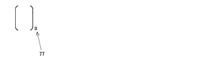
- the letter “D” indicated by the arrow 77 in FIG. 7 indicates the liquid crystal panel 20.
- the XYZ values of colors that can be reproduced by the input RGB signal RGB in are represented by the following equation (9).
- the XYZ values of colors that can be reproduced by the liquid crystal panel 20 are expressed by the following equation (10). Since the right side of the above equation (9) is equal to the right side of the above equation (10), the following equation (11) is established.
- the above equation (11) becomes the following equation (12).
- T is expressed by the following equation (13). Note that T in the above equations (12) and (13) is the above-described conversion coefficient.
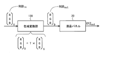
- the color gamut conversion unit 130 uses the conversion coefficient T calculated by the above equation (13) to store the data of each color included in the input RGB signal RGBin. By converting the value based on the above equation (12), the RGB signal RGB out for the liquid crystal panel is generated. By performing such color gamut conversion processing, if the faithful display mode is selected when the color gamut of the input RGB signal RGB in is completely included in the color gamut of the liquid crystal panel 20, the input RGB signal RGB The color based on in is faithfully reproduced.
- the input RGB signal RGB in is a signal conforming to the sRGB standard
- the following equation (14) is established.
- the conversion coefficient T is expressed by the following equation (16).
- the color gamut conversion unit 130 converts the data value of each color included in the input RGB signal RGB in based on the above equation (12) using the conversion coefficient T expressed by the above equation (16).
- the RGB signal RGB out for the liquid crystal panel is generated.
- the chromaticity coordinates of the white point in the standard of the input RGB signal RGBin and the chromaticity coordinates of the white point in the liquid crystal panel 20 are the same coordinates.
- the chromaticity coordinates of the two white points are different, the chromaticity coordinates of the white point in the liquid crystal panel 20 are used as the chromaticity coordinates of the white point in the standard of the input RGB signal RGBin before the above-described gamut conversion processing is performed.
- a process for matching the coordinates may be performed.
- the liquid crystal panel 20 displays character information based on the character information signal Sinfo output from the image processing unit 10. Specifically, when the faithful display mode is selected and the color gamut of the input RGB signal RGBin is completely included in the color gamut of the liquid crystal panel 20, the color is faithfully displayed, for example, as shown in FIG. Character information indicating the reproduction is displayed on the liquid crystal panel 20. Further, when the faithful display mode is selected and the color gamut of the input RGB signal RGB in is not completely included in the color gamut of the liquid crystal panel 20, for example, as shown in FIG. Character information indicating that is not reproduced is displayed on the liquid crystal panel 20. When a display mode other than the faithful display mode is selected, the character information as described above is not displayed on the liquid crystal panel 20.
- the image processing unit 10 of the liquid crystal display device 1 the color gamut of the input RGB signal RGB in the data value of each color included in the input RGB signal RGB in a color gamut of the liquid crystal panel 20
- a color gamut conversion unit 130 is provided for conversion based on this.
- the signal generated by the color gamut conversion unit 130 is given to the liquid crystal panel 20 as the RGB signal RGB out for the liquid crystal panel.
- the liquid crystal panel 20 has a linear characteristic with respect to the relationship between the gradation level of the input signal to the liquid crystal panel 20 (RGB signal RGB out for liquid crystal panel) and the display luminance. It was explained on the assumption. However, in general, the liquid crystal panel 20 has nonlinear characteristics. Therefore, in the present embodiment, it is assumed that the liquid crystal panel 20 having nonlinear characteristics is employed. Typically, the liquid crystal panel 20 has an output characteristic of gamma 2.2.
- the signal generated by the color gamut conversion unit 130 is given to the liquid crystal panel 20 as it is.
- the signal generated by the color gamut conversion unit 130 is subjected to gamma correction processing, and the signal after the gamma correction processing is given to the liquid crystal panel 20.
- a gamma correction processing unit 44 is provided after the color gamut conversion unit 130.
- a gamma correction processing unit 44 is performed by the gamma correction processing unit 44.
- the gamma correction processing is performed on the RGB signal RGB out for the liquid crystal panel.
- An input signal given to the liquid crystal display device is generally a signal that has been subjected to gamma correction processing. Therefore, in this modified example, in addition to the gamma correction processing unit 44 provided in the subsequent stage of the color gamut conversion unit 130, the degamma correction processing unit 42 is provided in the previous stage of the color gamut conversion unit 130. As shown in FIG. 12, in the de-gamma correction processing unit 42, de-gamma correction process is performed on the input RGB signal RGB in. Then, the signal after the degamma correction process is given to the color gamut conversion unit 130. As in the second embodiment, the gamma correction processing unit 44 performs gamma correction processing on the signal generated by the color gamut conversion unit 130. Then, the signal after the gamma correction processing is given to the liquid crystal panel 20.
- the input RGB signal RGB in is a signal that has been subjected to gamma correction processing, and the gradation level and display brightness of the input signal to the liquid crystal panel 20 (RGB signal RGB out for the liquid crystal panel)
- the degamma correction processing unit 42 performs degamma correction processing on the input RGB signal RGB in
- the gamma correction processing unit 44 performs liquid crystal panel processing.
- FIG. 13 is a block diagram showing the overall configuration of the liquid crystal display device 2 according to the third embodiment of the present invention.
- the liquid crystal display device 2 includes an image processing unit 50, a liquid crystal panel 20, and a display mode selection unit 30.
- the image processing unit 50 receives an input RGB signal RGB in given from the outside, and outputs a liquid crystal panel RGB signal RGB out . That is, the image processing unit 50 performs processing for converting the input RGB signal RGB in to the liquid crystal panel RGB signal RGB out .
- the display mode selection unit 30 receives the selection of the display mode by the user, and provides the image processing unit 10 with a display mode selection signal SEL indicating the display mode selected by the user.
- the liquid crystal panel 20 receives the RGB signal RGB out for the liquid crystal panel output from the image processing unit 10 and displays a color image based on the RGB signal RGB out for the liquid crystal panel.
- the image processing unit 50 includes a color gamut conversion unit 510, a color compression processing unit 540, a mode switching unit 550, and a conversion coefficient holding unit 560.
- the color gamut conversion unit 510 includes a first color gamut conversion unit 511 and a second color gamut conversion unit 512.
- the liquid crystal display device 1 according to the first embodiment is configured to faithfully reproduce colors for an input signal having an arbitrary color gamut as long as the color gamut of the liquid crystal panel 20 is not exceeded. It had been.
- the liquid crystal display device 2 according to this embodiment is configured to faithfully reproduce colors only for an input signal having a predetermined color gamut. For this reason, in the present embodiment, unlike the first embodiment, the image processing unit 50 is not provided with a color gamut determination unit or coefficient calculation unit.
- the conversion coefficient holding unit 560 includes a conversion coefficient T1 for use in the color gamut conversion process performed by the first color gamut conversion unit 511 and a conversion coefficient for use in the color gamut conversion process performed by the second color gamut conversion unit 512. T2 is held.
- the liquid crystal display device 2 can be provided with two types of input signals (input RGB signal RGB in ). That is, an input signal having the first color gamut and an input signal having the second color gamut can be supplied to the liquid crystal display device 2.
- a conversion coefficient T2 calculated based on the chromaticity coordinates of the three primary colors specified and the chromaticity coordinates of the three primary colors specifying the color gamut of the liquid crystal panel 20 is stored in the conversion coefficient holding unit 560 in advance. Note that the conversion coefficients T1 and T2 can be obtained in the same manner as in the first embodiment.
- the input signal may be supplied to the liquid crystal display device 2.
- the first color gamut conversion unit 511 performs color gamut conversion processing on the input RGB signal RGB in having the first color gamut using the conversion coefficient T1 held in the conversion coefficient holding unit 560.
- the second color gamut conversion unit 512 performs color gamut conversion processing on the input RGB signal RGB in having the second color gamut using the conversion coefficient T2 held in the conversion coefficient holding unit 560.
- the color compression processing unit 540 performs processing for compressing the gradation value on the input RGB signal RGB in .
- the signal output from the first color gamut conversion unit 511 is referred to as an internal signal d4
- the signal output from the second color gamut conversion unit 512 is referred to as an internal signal d5.
- a signal output from the processing unit 540 is referred to as an internal signal d6.
- the mode switching unit 550 switches a signal given to the liquid crystal panel 20 as the RGB signal RGB out for the liquid crystal panel according to the display mode selection signal SEL given from the display mode selection unit 30.
- the display mode selection signal SEL given from the display mode selection unit 30.
- four display modes of “first faithful display mode”, “second faithful display mode”, “color compression display mode”, and “through display mode” are provided.
- First faithful display mode and the second faithful display mode is a mode for faithfully reproducing the colors based on the input RGB signal RGB in.
- the color compression display mode is a mode for displaying a color that does not make the person feel as uncomfortable as possible.
- the through display mode is a mode for performing display by using the gradation value of the input RGB signal RGB in as it is as the gradation value of the RGB signal RGB out for the liquid crystal panel.
- the mode switching unit 550 When the display mode selection signal SEL indicates the “first faithful display mode”, the mode switching unit 550 is in a state where the point K and the point K4 are connected. Thereby, the internal signal d4 output from the first color gamut conversion unit 511 is given to the liquid crystal panel 20 as the RGB signal RGB out for the liquid crystal panel.
- the display mode selection signal SEL indicates the “second faithful display mode”
- the mode switching unit 550 is in a state where the point K and the point K5 are connected.
- the internal signal d5 output from the second color gamut conversion unit 512 is provided to the liquid crystal panel 20 as the RGB signal RGB out for the liquid crystal panel.
- the mode switching unit 550 When the display mode selection signal SEL indicates “color compression display mode”, the mode switching unit 550 is in a state where the point K and the point K6 are connected. As a result, the internal signal d6 output from the color compression processing unit 540 is provided to the liquid crystal panel 20 as the RGB signal RGB out for the liquid crystal panel.
- the display mode selection signal SEL indicates “through display mode”
- the mode switching unit 550 is in a state where the point K and the point K7 are connected. As a result, the input RGB signal RGB in is directly supplied to the liquid crystal panel 20 as the RGB signal RGB out for the liquid crystal panel.
- the image processing unit 50 of the liquid crystal display device 2 the color gamut of the input RGB signal RGB in the data value of each color included in the input RGB signal RGB in a color gamut of the liquid crystal panel 20
- a color gamut conversion unit 510 is provided for conversion based on this.
- the faithful display mode the first faithful display mode and the second faithful display mode
- the signal generated by the color gamut conversion unit 510 is given to the liquid crystal panel 20 as the RGB signal RGB out for the liquid crystal panel. It is done.
- the color represented by the input RGB signal RGB in it is possible to faithfully reproduce the LCD panel 20.
- a predetermined type of input signal is given to the liquid crystal display device 2.
- the image processing unit 50 is not provided with a color gamut determination unit or a coefficient calculation unit. Therefore, the configuration of the image processing unit 50 becomes simpler than the configuration in the first embodiment. This makes it possible to realize a liquid crystal display device that can faithfully reproduce colors at low cost.
Landscapes
- Engineering & Computer Science (AREA)
- Physics & Mathematics (AREA)
- Computer Hardware Design (AREA)
- General Physics & Mathematics (AREA)
- Theoretical Computer Science (AREA)
- Chemical & Material Sciences (AREA)
- Crystallography & Structural Chemistry (AREA)
- Multimedia (AREA)
- Signal Processing (AREA)
- Control Of Indicators Other Than Cathode Ray Tubes (AREA)
Abstract
色を忠実に再現することのできる液晶表示装置を提供する。 液晶表示装置(1)には、入力RGB信号(RGBin)に含まれる各色のデータ値を当該入力RGB信号(RGBin)の色域と液晶パネル(20)の色域とに基づいて変換することによって液晶パネル(20)に与えるための液晶パネル用RGB信号(RGBout)を生成する色域変換部(130)が設けられる。入力RGB信号(RGBin)の色域が液晶パネル(20)の色域に包含されているときには、色域変換部(130)で生成された液晶パネル用RGB信号(RGBout)が液晶パネル20に与えられることによって、入力RGB信号(RGBin)の表す色が液晶パネル(20)に忠実に再現される。
Description
本発明は、液晶表示装置および液晶表示装置における画像表示方法に関し、特に、液晶表示装置における色域変換処理を用いた色再現技術に関する。
近年、液晶表示装置などの表示装置の高解像度化が顕著である。また、表示装置の色再現能力の向上も顕著である。現在、表示装置の色再現能力を表す指標としてNTSC比が採用されているところ、NTSC比が約150%の液晶表示装置も実現されている。ところが、一般に、表示装置,印刷装置,撮像装置などにおいては機種毎に色域(「色再現範囲」などとも呼ばれている。)が異なっている。また、例えばカラーテレビジョン装置においては、採用されるテレビジョン方式毎に、入力映像信号の色域が異なっている。このようなことから、色域の相違に関わらず入力データにできるだけ忠実な色の出力が行われるよう、入力データに対して各種の変換処理を行うことが提案されている。なお、本明細書においては、表示装置などの画像出力装置の色域と当該画像出力装置への入力信号の色域との相違に関わらず入力信号にできるだけ忠実な色が表示されるよう入力信号の値に補正を施す処理のことを「色域変換処理」という。
本件発明に関連して、以下の先行技術文献が知られている。日本の特開2004-110647号公報には、カラーマネージメントシステムにおいて色飛びや色あせが生じることのないよう色変換係数を決定できるようにした色変換係数作成方法についての発明が開示されている。また、日本の特開2003-134351号公報には、入力プロファイル,表示プロファイル,色空間変換プロファイルなどを用いて色変換処理を行うスペクトル・色再現システムについての発明が開示されている。
ところで、近年、パーソナルコンピュータ,テレビジョン装置,モバイル端末装置などを利用したいわゆるネットショッピングが盛んに行われている。しかしながら、注文時に画面を通して商品の購入者に知覚される色合いと実際の商品の色合いとが異なることがある。このようなことは商品の提供者と商品の購入者との間のトラブルの原因となっている。また、医療分野で用いられる表示装置(特に高度技術を要する手術の支援システムなどで用いられる表示装置)に関しては、色を忠実に再現することが強く要求されている。
注文時に画面を通して商品の購入者に知覚される色合いと実際の商品の色合いとが異なる原因として、以下の2点を挙げることができる。1点目は、従来の表示装置は色再現能力が低かったため、デジタルカメラやテレビジョン装置での画像・映像処理においては、被写体の色を忠実に再現することよりも被写体をきれいに見せることが重視されていたという点である。2点目は、表示コンテンツの色域が表示装置の表示能力(色再現能力)を超えているという点である。これについて、図14を参照しつつ説明する。図14は、CIE1931のxy色度図である。図14では、人の目で見ることのできる色の範囲を符号91の点線で表し、NTSC規格における色域を符号92の太線で表し、sRGB規格における色域を符号93の実線で表している。NTSC規格における色域は、頂点をa1,b1,およびc1とする三角形で表されている。sRGB規格における色域は、頂点をa2,b2,およびc2とする三角形で表されている。上述したように表示装置の色再現能力を表す指標としてNTSC比が採用されているところ、sRGB規格のNTSC比は71パーセントである。すなわち、NTSC規格における色域は、sRGB規格における色域よりも大きい。しかしながら、図14に示すように頂点c2の色度座標はNTSC規格における色域の範囲外にあるので、NTSC規格における色域と同じ色域を有する表示装置は、入力信号としてsRGB規格に準拠する信号が与えられたとき、当該入力信号に基づく本来の色を完全に再現することはできない。
日本の特開2004-110647号公報に記載された色変換係数作成方法によれば、表示装置の色域を超えた色データが存在すれば、当該色データが表示装置の色域に含まれるように線形圧縮が施される。すなわち、人に違和感を与えることがないように色を表示しているだけであって、色を忠実に再現しているわけではない。また、日本の特開2003-134351号公報に記載されたスペクトル・色再現システムによっても、色が完全に忠実に再現されるわけではない。
そこで本発明は、色を忠実に再現することのできる液晶表示装置を提供することを目的とする。さらに、本発明は、表示されている色についてユーザに誤解を与えることのないよう、色を忠実に再現しているか否かの情報をユーザに示すことのできる液晶表示装置を提供することを目的とする。
本発明の第1の局面は、入力信号に基づくカラー画像を表示するための液晶パネルを有する液晶表示装置であって、
前記入力信号に含まれる各色のデータ値を前記入力信号の色域と前記液晶パネルの色域とに基づいて変換することによって、前記液晶パネルに与えるための表示用画像信号を生成する色域変換部を備え、
前記入力信号の色域が前記液晶パネルの色域に包含されている限りにおいて、前記色域変換部で生成された表示用画像信号が前記液晶パネルに与えられることによって、前記入力信号の表す色が前記液晶パネルに忠実に再現されることを特徴とする。
前記入力信号に含まれる各色のデータ値を前記入力信号の色域と前記液晶パネルの色域とに基づいて変換することによって、前記液晶パネルに与えるための表示用画像信号を生成する色域変換部を備え、
前記入力信号の色域が前記液晶パネルの色域に包含されている限りにおいて、前記色域変換部で生成された表示用画像信号が前記液晶パネルに与えられることによって、前記入力信号の表す色が前記液晶パネルに忠実に再現されることを特徴とする。
本発明の第2の局面は、本発明の第1の局面において、
前記入力信号の色域が前記液晶パネルの色域に包含されているか否かを判別して、判別結果を示す判別信号を前記液晶パネルに与える色域判別部を更に備え、
前記液晶パネルでは、前記判別信号に基づいて、前記入力信号の表す色が忠実に再現されているか否かを示す情報が表示されることを特徴とする。
前記入力信号の色域が前記液晶パネルの色域に包含されているか否かを判別して、判別結果を示す判別信号を前記液晶パネルに与える色域判別部を更に備え、
前記液晶パネルでは、前記判別信号に基づいて、前記入力信号の表す色が忠実に再現されているか否かを示す情報が表示されることを特徴とする。
本発明の第3の局面は、本発明の第2の局面において、
前記色域判別部は、前記入力信号の色域を特定する3原色の色度座標の全てが前記液晶パネルの色域を表す三角形の内部に含まれていれば、前記入力信号の色域は前記液晶パネルの色域に包含されている旨の判定を行うことを特徴とする。
前記色域判別部は、前記入力信号の色域を特定する3原色の色度座標の全てが前記液晶パネルの色域を表す三角形の内部に含まれていれば、前記入力信号の色域は前記液晶パネルの色域に包含されている旨の判定を行うことを特徴とする。
本発明の第4の局面は、本発明の第3の局面において、
前記入力信号の色域を特定する3原色の各色度座標を原色色度座標と定義し、前記液晶パネルの色域を表す三角形をパネル色域三角形と定義したとき、前記色域判別部は、前記パネル色域三角形の内部に存在する座標と前記原色色度座標とを結ぶ線分が前記パネル色域三角形を構成する3つの線分のいずれとも交差しなければ、前記原色色度座標は前記パネル色域三角形の内部に含まれている旨の判定を行うことを特徴とする。
前記入力信号の色域を特定する3原色の各色度座標を原色色度座標と定義し、前記液晶パネルの色域を表す三角形をパネル色域三角形と定義したとき、前記色域判別部は、前記パネル色域三角形の内部に存在する座標と前記原色色度座標とを結ぶ線分が前記パネル色域三角形を構成する3つの線分のいずれとも交差しなければ、前記原色色度座標は前記パネル色域三角形の内部に含まれている旨の判定を行うことを特徴とする。
本発明の第5の局面は、本発明の第4の局面において、
前記色域判別部は、前記液晶パネルの色域を特定する3原色の色度座標についてのx座標の平均値およびy座標の平均値によって特定される座標と前記原色色度座標とを結ぶ線分が前記パネル色域三角形を構成する3つの線分のいずれかとも交差しなければ、前記原色色度座標は前記パネル色域三角形の内部に含まれている旨の判定を行うことを特徴とする。
前記色域判別部は、前記液晶パネルの色域を特定する3原色の色度座標についてのx座標の平均値およびy座標の平均値によって特定される座標と前記原色色度座標とを結ぶ線分が前記パネル色域三角形を構成する3つの線分のいずれかとも交差しなければ、前記原色色度座標は前記パネル色域三角形の内部に含まれている旨の判定を行うことを特徴とする。
本発明の第6の局面は、本発明の第1の局面または本発明の第2の局面において、
前記入力信号の色域を特定する3原色の色度座標と前記液晶パネルの色域を特定する3原色の色度座標とに基づいて、前記入力信号に含まれる各色のデータ値を変換する際に前記色域変換部によって用いられるべき変換係数を算出する係数算出部を更に備えることを特徴とする。
前記入力信号の色域を特定する3原色の色度座標と前記液晶パネルの色域を特定する3原色の色度座標とに基づいて、前記入力信号に含まれる各色のデータ値を変換する際に前記色域変換部によって用いられるべき変換係数を算出する係数算出部を更に備えることを特徴とする。
本発明の第7の局面は、本発明の第6の局面において、
前記入力信号および前記表示用画像信号は、RGB表色系のデータであって、
前記入力信号と前記表示用画像信号との関係は、前記変換係数をTとして下記の式(A)で表され、
前記係数算出部は、前記入力信号の三刺激値であるRGB値を前記入力信号の色域に応じてXYZ表色系のデータの三刺激値であるXYZ値に変換するための下記の式(B)と、前記表示用画像信号の三刺激値であるRGB値を前記液晶パネルの色域に応じてXYZ表色系のデータの三刺激値であるXYZ値に変換するための下記の式(C)とに基づいて、前記変換係数Tを下記の式(D)によって求めることを特徴とする。




前記入力信号および前記表示用画像信号は、RGB表色系のデータであって、
前記入力信号と前記表示用画像信号との関係は、前記変換係数をTとして下記の式(A)で表され、
前記係数算出部は、前記入力信号の三刺激値であるRGB値を前記入力信号の色域に応じてXYZ表色系のデータの三刺激値であるXYZ値に変換するための下記の式(B)と、前記表示用画像信号の三刺激値であるRGB値を前記液晶パネルの色域に応じてXYZ表色系のデータの三刺激値であるXYZ値に変換するための下記の式(C)とに基づいて、前記変換係数Tを下記の式(D)によって求めることを特徴とする。
本発明の第8の局面は、本発明の第1の局面において、
前記表示用画像信号に対してガンマ補正処理を施すガンマ補正処理部を更に備えることを特徴とする。
前記表示用画像信号に対してガンマ補正処理を施すガンマ補正処理部を更に備えることを特徴とする。
本発明の第9の局面は、本発明の第8の局面において、
前記入力信号に対してデガンマ補正処理を施すデガンマ補正処理部を更に備えることを特徴とする。
前記入力信号に対してデガンマ補正処理を施すデガンマ補正処理部を更に備えることを特徴とする。
本発明の第10の局面は、本発明の第1の局面において、
前記入力信号に含まれる各色のデータ値を変換する際に前記色域変換部によって用いられるべき変換係数を前記入力信号の種類毎に予め保持するための変換係数保持部を更に備え、
前記色域変換部は、前記入力信号の種類に応じて、前記変換係数保持部に保持されている変換係数を用いて前記入力信号に含まれる各色のデータ値を変換することを特徴とする。
前記入力信号に含まれる各色のデータ値を変換する際に前記色域変換部によって用いられるべき変換係数を前記入力信号の種類毎に予め保持するための変換係数保持部を更に備え、
前記色域変換部は、前記入力信号の種類に応じて、前記変換係数保持部に保持されている変換係数を用いて前記入力信号に含まれる各色のデータ値を変換することを特徴とする。
本発明の第11の局面は、本発明の第1の局面において、
前記入力信号の表す色を前記液晶パネルに忠実に再現するための忠実表示モードを含む複数の表示モードのうちの1つを外部から選択するための表示モード選択部を更に備え、
前記表示モード選択部によって前記忠実表示モードが選択されているときには、前記色域変換部で生成された表示用画像信号が前記液晶パネルに与えられることを特徴とする。
前記入力信号の表す色を前記液晶パネルに忠実に再現するための忠実表示モードを含む複数の表示モードのうちの1つを外部から選択するための表示モード選択部を更に備え、
前記表示モード選択部によって前記忠実表示モードが選択されているときには、前記色域変換部で生成された表示用画像信号が前記液晶パネルに与えられることを特徴とする。
本発明の第12の局面は、本発明の第11の局面において、
前記表示モード選択部によって前記忠実表示モードが選択されているにもかかわらず前記入力信号の色域が前記液晶パネルの色域に完全には包含されていないときには、前記入力信号の表す色が忠実には再現されていないことを示す情報が前記液晶パネルに表示されることを特徴とする。
前記表示モード選択部によって前記忠実表示モードが選択されているにもかかわらず前記入力信号の色域が前記液晶パネルの色域に完全には包含されていないときには、前記入力信号の表す色が忠実には再現されていないことを示す情報が前記液晶パネルに表示されることを特徴とする。
本発明の第13の局面は、本発明の第11の局面において、
前記表示モード選択部によって前記忠実表示モードが選択されているときにだけ、前記入力信号の表す色が忠実に再現されているか否かを示す情報が前記液晶パネルに表示されることを特徴とする。
前記表示モード選択部によって前記忠実表示モードが選択されているときにだけ、前記入力信号の表す色が忠実に再現されているか否かを示す情報が前記液晶パネルに表示されることを特徴とする。
本発明の第14の局面は、本発明の第1の局面において、
前記液晶パネルの色域は、sRGB規格の色域を包含していることを特徴とする。
前記液晶パネルの色域は、sRGB規格の色域を包含していることを特徴とする。
本発明の第15の局面は、入力信号に基づくカラー画像を表示するための液晶パネルを有する液晶表示装置における画像表示方法であって、
前記入力信号に含まれる各色のデータ値を前記入力信号の色域と前記液晶パネルの色域とに基づいて変換することによって、前記液晶パネルに与えるための表示用画像信号を生成する色域変換ステップと、
前記液晶パネルに前記カラー画像を表示する表示ステップと
を含み、
前記表示ステップでは、前記入力信号の色域が前記液晶パネルの色域に包含されている限りにおいて、前記色域変換ステップで生成された表示用画像信号が前記液晶パネルに与えられることによって、前記入力信号の表す色が前記液晶パネルに忠実に再現されることを特徴とする。
前記入力信号に含まれる各色のデータ値を前記入力信号の色域と前記液晶パネルの色域とに基づいて変換することによって、前記液晶パネルに与えるための表示用画像信号を生成する色域変換ステップと、
前記液晶パネルに前記カラー画像を表示する表示ステップと
を含み、
前記表示ステップでは、前記入力信号の色域が前記液晶パネルの色域に包含されている限りにおいて、前記色域変換ステップで生成された表示用画像信号が前記液晶パネルに与えられることによって、前記入力信号の表す色が前記液晶パネルに忠実に再現されることを特徴とする。
本発明の第1の局面によれば、入力信号に含まれる各色のデータ値を当該入力信号の色域と液晶パネルの色域とに基づいて変換する色域変換部が設けられている。このため、入力信号の色域が液晶パネルの色域に包含されている限りにおいて、入力信号の表す色を液晶パネルに忠実に再現することが可能となる。
本発明の第2の局面によれば、ユーザは、色が忠実に再現されているか否かを認識することができる。このため、液晶パネルに表示されている色について、ユーザに誤解を与えることが防止される。これにより、例えばネットショッピングが行われた際に、画面を通して商品の購入者に知覚される色合いと実際の商品の色合いとが異なることに起因するトラブルの発生が防止される。
本発明の第3の局面によれば、入力信号の表す色を液晶パネルに忠実に再現することができるか否かを確実に判別することが可能となる。
本発明の第4の局面によれば、本発明の第3の局面と同様、入力信号の表す色を液晶パネルに忠実に再現することができるか否かを確実に判別することが可能となる。
本発明の第5の局面によれば、本発明の第3の局面と同様、入力信号の表す色を液晶パネルに忠実に再現することができるか否かを確実に判別することが可能となる。
本発明の第6の局面によれば、入力信号の色域に応じて、色域変換処理用の変換係数が算出される。このため、入力信号の色域が液晶パネルの色域に包含されている限りにおいて、任意の色域を有する入力信号に基づいて、液晶パネルに忠実に色を再現することが可能となる。
本発明の第7の局面によれば、入力信号の色域と液晶パネルの色域とを考慮して、予め定められた式に基づいて、色域変換処理用の変換係数が算出される。このため、入力信号の色域が液晶パネルの色域に包含されている限りにおいて、入力信号の表す色を確実に液晶パネルに忠実に再現することが可能となる。
本発明の第8の局面によれば、表示用画像信号(液晶パネルへの入力信号)の階調レベルと表示輝度との関係について液晶パネルが非線形の特性を有している場合でも、表示用画像信号に対してガンマ補正処理が施されることによって、本発明の第1の局面と同様の効果が得られる。
本発明の第9の局面によれば、入力信号がガンマ補正処理が施された信号であって、かつ、表示用画像信号(液晶パネルへの入力信号)の階調レベルと表示輝度との関係について液晶パネルが非線形の特性を有している場合でも、入力信号に対してデガンマ補正処理が施され、かつ、表示用画像信号に対してガンマ補正処理が施されることによって、本発明の第1の局面と同様の効果が得られる。
本発明の第10の局面によれば、液晶表示装置には色域変換処理用の変換係数を保持するための色域変換部が設けられる。このため、変換係数を算出するための構成要素を液晶表示装置に設ける必要がない。従って、色を忠実に再現することのできる液晶表示装置を低コストで実現することが可能となる。
本発明の第11の局面によれば、色を忠実に再現させるか否かをユーザが選択することが可能となる。
本発明の第12の局面によれば、本発明の第2の局面と同様、液晶パネルに表示されている色について、ユーザに誤解を与えることが防止される。
本発明の第13の局面によれば、ユーザにとって不必要な情報が液晶パネルに表示されることが防止される。
本発明の第14の局面によれば、入力信号がsRGB規格に準拠している限りにおいて、入力信号の表す色を液晶パネルに忠実に再現することが可能となる。
本発明の第15の局面によれば、本発明の第1の局面と同様の効果を液晶表示装置における画像表示方法において奏することができる。
以下、添付図面を参照しつつ本発明の実施形態について説明する。
<1.第1の実施形態>
<1.1 全体構成>
図1は、本発明の第1の実施形態に係る液晶表示装置1の全体構成を示すブロック図である。図1に示すように、この液晶表示装置1には、画像処理部10と液晶パネル20と表示モード選択部30とが含まれている。なお、表示モード選択部30は、液晶表示装置1の外部に設けられていても良い。画像処理部10は、外部から与えられる入力RGB信号RGBin(入力信号)を受け取り、液晶パネル用RGB信号RGBout(表示用画像信号)を出力する。すなわち、画像処理部10では、入力RGB信号RGBinを液晶パネル用RGB信号RGBoutに変換する処理が行われる。その変換は、入力RGB信号RGBinの規格における3原色の色度座標Cinおよび表示モード選択部30から与えられる表示モード選択信号SELに基づいて行われる。また、画像処理部10は、後述する文字情報用信号Sinfoを液晶パネル20に与える。表示モード選択部30は、ユーザによる表示モードの選択を受け付け、ユーザによって選択された表示モードを示す表示モード選択信号SELを画像処理部10に与える。液晶パネル20は、画像処理部10から出力される液晶パネル用RGB信号RGBoutを受け取り、当該液晶パネル用RGB信号RGBoutに基づくカラー画像を表示する。また、液晶パネル20は、画像処理部10から出力される文字情報用信号Sinfoを受け取り、当該文字情報用信号Sinfoに基づく文字情報を表示する。なお、本実施形態においては、文字情報用信号Sinfoによって判別信号が実現されている。
<1.1 全体構成>
図1は、本発明の第1の実施形態に係る液晶表示装置1の全体構成を示すブロック図である。図1に示すように、この液晶表示装置1には、画像処理部10と液晶パネル20と表示モード選択部30とが含まれている。なお、表示モード選択部30は、液晶表示装置1の外部に設けられていても良い。画像処理部10は、外部から与えられる入力RGB信号RGBin(入力信号)を受け取り、液晶パネル用RGB信号RGBout(表示用画像信号)を出力する。すなわち、画像処理部10では、入力RGB信号RGBinを液晶パネル用RGB信号RGBoutに変換する処理が行われる。その変換は、入力RGB信号RGBinの規格における3原色の色度座標Cinおよび表示モード選択部30から与えられる表示モード選択信号SELに基づいて行われる。また、画像処理部10は、後述する文字情報用信号Sinfoを液晶パネル20に与える。表示モード選択部30は、ユーザによる表示モードの選択を受け付け、ユーザによって選択された表示モードを示す表示モード選択信号SELを画像処理部10に与える。液晶パネル20は、画像処理部10から出力される液晶パネル用RGB信号RGBoutを受け取り、当該液晶パネル用RGB信号RGBoutに基づくカラー画像を表示する。また、液晶パネル20は、画像処理部10から出力される文字情報用信号Sinfoを受け取り、当該文字情報用信号Sinfoに基づく文字情報を表示する。なお、本実施形態においては、文字情報用信号Sinfoによって判別信号が実現されている。
図2は、本実施形態における液晶パネル20の色域とsRGB規格における色域との関係を説明するためのxy色度図である。図2において、人の目で見ることのできる色の範囲を符号71の曲線で表し、本実施形態における液晶パネル20の色域を符号72の三角形(頂点をa3,b3,およびc3とする三角形)で表し、sRGB規格における色域を符号73の三角形(頂点をa2,b2,およびc2とする三角形)で表している。図2に示すように、sRGB規格における色域を表す三角形の頂点a2,b2,およびc2は全て液晶パネル20の色域を表す三角形の内部に含まれている。すなわち、本実施形態における液晶パネル20の色域は、sRGB規格の色域を完全に包含している。従って、入力RGB信号RGBinがsRGB規格に準拠した信号であれば、本実施形態における液晶パネル20は、入力RGB信号RGBinの表す色を忠実に再現することができる。
<1.2 画像処理部の構成>
図1に示すように、画像処理部10には、色域判別部110,係数算出部120,色域変換部130,色圧縮処理部140,およびモード切替部150が含まれている。色域判別部110は、入力RGB信号RGBinの規格における3原色の色度座標Cinと液晶パネル20における3原色の色度座標Cpanelとに基づいて、入力RGB信号RGBinの色域が液晶パネル20の色域に完全に包含されているか否かを判別する。換言すれば、色域判別部110は、入力RGB信号RGBinに基づく色を液晶パネル20が忠実に再現することができるか否かを判別する。なお、以下においては、色域判別部110で行われるこの処理のことを「色域判別処理」という。
図1に示すように、画像処理部10には、色域判別部110,係数算出部120,色域変換部130,色圧縮処理部140,およびモード切替部150が含まれている。色域判別部110は、入力RGB信号RGBinの規格における3原色の色度座標Cinと液晶パネル20における3原色の色度座標Cpanelとに基づいて、入力RGB信号RGBinの色域が液晶パネル20の色域に完全に包含されているか否かを判別する。換言すれば、色域判別部110は、入力RGB信号RGBinに基づく色を液晶パネル20が忠実に再現することができるか否かを判別する。なお、以下においては、色域判別部110で行われるこの処理のことを「色域判別処理」という。
また、色域判別部110は、判別結果と表示モード選択部30から与えられる表示モード選択信号SELとに基づいて、文字情報用信号Sinfoを液晶パネル20に与える。詳しくは、表示モード選択信号SELが後述する「忠実表示モード」を示していて、かつ、「入力RGB信号RGBinの色域が液晶パネル20の色域に完全に包含されている」という判別結果が得られているときには、色域判別部110は、色が忠実に再現されていることを示す文字情報を表示するための文字情報用信号Sinfoを液晶パネル20に与える。また、表示モード選択信号SELが「忠実表示モード」を示していて、かつ、「入力RGB信号RGBinの色域が液晶パネル20の色域に完全には包含されていない」という判別結果が得られているときには、色域判別部110は、色が忠実には表示されていないことを示す文字情報を表示するための文字情報用信号Sinfoを液晶パネル20に与える。なお、表示モード選択信号SELが「忠実表示モード」以外の表示モードを示しているときには、上述のような文字情報を表示しないことを指示する文字情報用信号Sinfoが液晶パネル20に与えられる。
係数算出部120は、入力RGB信号RGBinの規格における3原色の色度座標Cinと液晶パネル20における3原色の色度座標Cpanelとに基づいて、色域変換部130で行われる色域変換処理で用いるための変換係数Tを算出する。なお、色域変換処理および変換係数Tの算出についての詳しい説明は後述する。色域変換部130は、係数算出部120で算出された変換係数Tを用いて、入力RGB信号RGBinに色域変換処理を施す。色圧縮処理部140は、入力RGB信号RGBinの色域が液晶パネル20の色域よりも大きいときに人に違和感を与えることがないような色が表示されるよう、入力RGB信号RGBinに対して階調値を圧縮する処理を施す。なお、以下においては、色域変換部130から出力される信号のことを内部信号d1といい、色圧縮処理部140から出力される信号のことを内部信号d2という。
モード切替部150は、表示モード選択部30から与えられる表示モード選択信号SELに応じて、液晶パネル用RGB信号RGBoutとして液晶パネル20に与えられる信号を切り替える。本実施形態においては、「忠実表示モード」,「色圧縮表示モード」,および「スルー表示モード」の3つの表示モードが設けられている。忠実表示モードは、入力RGB信号RGBinの表す色を忠実に再現するためのモードである。色圧縮表示モードは、できるだけ人に違和感を与えることのないような色を表示するためのモードである。スルー表示モードは、入力RGB信号RGBinの階調値をそのまま液晶パネル用RGB信号RGBoutの階調値にして表示を行うためのモードである。スルー表示モードによれば、入力RGB信号RGBinの色域よりも液晶パネル20の色域の方が大きいときに、液晶パネル20の色再現能力を充分に活かした表示(例えば、派手な表示)を行うことが可能となる。
表示モード選択信号SELが「忠実表示モード」を示しているとき、モード切替部150では、点Kと点K1とが接続された状態となる。これにより、色域変換部130から出力された内部信号d1が液晶パネル用RGB信号RGBoutとして液晶パネル20に与えられる。表示モード選択信号SELが「色圧縮表示モード」を示しているとき、モード切替部150では、点Kと点K2とが接続された状態となる。これにより、色圧縮処理部140から出力された内部信号d2が液晶パネル用RGB信号RGBoutとして液晶パネル20に与えられる。表示モード選択信号SELが「スルー表示モード」を示しているとき、モード切替部150では、点Kと点K3とが接続された状態となる。これにより、入力RGB信号RGBinがそのまま液晶パネル用RGB信号RGBoutとして液晶パネル20に与えられる。
<1.3 色域判別処理>
本実施形態における色域判別処理について詳しく説明する。本実施形態においては、入力RGB信号RGBinの規格における3原色の色度座標Cinの全てが液晶パネル20の色域を表す三角形の内部に含まれていれば、入力RGB信号RGBinの色域は液晶パネル20の色域に包含されている旨の判定が行われる。このような判定を行うために、入力RGB信号RGBinの規格における3原色の色度座標Cinのそれぞれについて、液晶パネル20の色域を表す三角形の内部に含まれているか否かの判別が以下のように行われる。
本実施形態における色域判別処理について詳しく説明する。本実施形態においては、入力RGB信号RGBinの規格における3原色の色度座標Cinの全てが液晶パネル20の色域を表す三角形の内部に含まれていれば、入力RGB信号RGBinの色域は液晶パネル20の色域に包含されている旨の判定が行われる。このような判定を行うために、入力RGB信号RGBinの規格における3原色の色度座標Cinのそれぞれについて、液晶パネル20の色域を表す三角形の内部に含まれているか否かの判別が以下のように行われる。
まず、或る点(以下、「着目点」という。)が三角形の内部に含まれているか否かを本実施形態ではどのような手法を用いて判別するのかについて説明する。着目点P,三角形の内部に存在する任意の点Q,および三角形の或る1つの辺L1に着目すると、着目点Pが辺L1を基準として点Qと同じ側に存在していなければ、着目点Pは必ず三角形の外部に存在する(図3参照)。このように着目点Pが辺L1を基準として点Qと同じ側に存在していないときには、着目点Pと点Qとを結ぶ線分は辺L1と交差する。三角形は3つの辺で構成されているので、着目点Pと点Qとを結ぶ線分が三角形を構成する3つの辺のいずれかと交差すれば、着目点Pは三角形の外部に存在する。一方、着目点Pと点Qとを結ぶ線分が三角形を構成する3つの辺のいずれとも交差していなければ、着目点Pは三角形の内部に存在する。
ところで、本実施形態においては、上記任意の点Qとして、液晶パネル20の色域を表す三角形の3つの頂点についてのx座標の平均値およびy座標の平均値によって特定される座標点(以下、「パネル色域中心点」という。)が採用される。何故ならば、三角形の中心は必ず当該三角形の内部に存在するからである。なお、液晶パネル20の色域を表す三角形の内部に存在する点であれば、パネル色域中心点以外の点が上記任意の点Qとして採用されても良い。
例えば、図4に示すようにパネル色域中心点Wと或る点P1とを結ぶ線分が液晶パネル20の色域を表す三角形の3つの辺のいずれとも交差していないときには、点P1は当該三角形の内部に存在する。また、図4に示すようにパネル色域中心点Wと或る点P2とを結ぶ線分が液晶パネル20の色域を表す三角形の1辺と交差しているときには、点P2は当該三角形の外部に存在する。
本実施形態においては、以上のような考え方に基づいて、入力RGB信号RGBinの規格における3原色の色度座標Cinのそれぞれについて、液晶パネル20の色域を表す三角形の内部に含まれているか否かの判別が行われる。そして、上述したように、入力RGB信号RGBinの規格における3原色の色度座標Cinの全てが液晶パネル20の色域を表す三角形の内部に含まれていれば、入力RGB信号RGBinの色域は液晶パネル20の色域に包含されている旨の判定が行われる。一方、入力RGB信号RGBinの規格における3原色の色度座標Cinの少なくとも1つが液晶パネル20の色域を表す三角形の外部に存在していれば、入力RGB信号RGBinの色域は液晶パネル20の色域に完全には包含されていない旨の判定が行われる。
以上より、入力RGB信号RGBinの規格における3原色の色度座標Cinのそれぞれを「原色色度座標」と定義し、液晶パネル20の色域を表す三角形を「パネル色域三角形」と定義すると、この色域判別処理では以下のような判定が行われる。パネル色域三角形の内部に存在する座標と原色色度座標とを結ぶ線分がパネル色域三角形を構成する3つの線分のいずれとも交差しなければ、「原色色度座標はパネル色域三角形の内部に含まれている」旨の判定が行われる。さらに詳しくは、液晶パネル20の色域を特定する3原色の色度座標についてのx座標の平均値およびy座標の平均値によって特定される座標と原色色度座標とを結ぶ線分がパネル色域三角形を構成する3つの線分のいずれとも交差しなければ、「原色色度座標はパネル色域三角形の内部に含まれている」旨の判定が行われる。
この色域判別処理を図14に示した例に適用すると、点a2および点b2はNTSC規格における色域を表す三角形の内部に含まれているが、点c2は当該三角形の外部に存在する。従って、sRGB規格における色域は、NTSC規格における色域に完全には包含されていない。また、図2においては、点a2,点b2,および点c2は全て液晶パネル20の色域を表す三角形の内部に含まれている。従って、sRGB規格における色域は、本実施形態における液晶パネル20の色域に完全に包含されている。
図5は、sRGB規格の色域,NTSC規格の色域,および液晶パネル20の色域(一例)のそれぞれについての3原色および白色点の色度座標を示す図である。本実施形態においては、説明の便宜上、sRGB規格における白色点の色度座標と液晶パネル20における白色点の色度座標とが同じ座標に設定されている。この白色点の色度座標は、色域を表す三角形の内部に必ず存在する。従って、色域判別処理が行われる際の上記任意の点Qとして、液晶パネル20における白色点が採用されても良い。
<1.4 色域変換処理>
本実施形態における色域変換処理について詳しく説明する。ここでは、まず、RGB表色系における3刺激値からXYZ表色系における3刺激値を求める方法を説明する。なお、RGB表色系は規格や機器に依存する色の表現方法であるのに対し、XYZ表色系は規格や機器に依存しない色の表現方法である。すなわち、RGB値は色を正確には表現していないのに対し、XYZ値は一意に定まる色を表現している。
本実施形態における色域変換処理について詳しく説明する。ここでは、まず、RGB表色系における3刺激値からXYZ表色系における3刺激値を求める方法を説明する。なお、RGB表色系は規格や機器に依存する色の表現方法であるのに対し、XYZ表色系は規格や機器に依存しない色の表現方法である。すなわち、RGB値は色を正確には表現していないのに対し、XYZ値は一意に定まる色を表現している。
ここで、3原色RGBが取り得る値の範囲を0以上1以下とし、原刺激Rだけによる色度座標をxR,yR,zRとし、原刺激Gだけによる色度座標をxG,yG,zGとし、原刺激Bだけによる色度座標をxB,yB,zBとする。これに関し、例えば、xR,yR,zRの色度座標は、「R≠0」かつ「G=0」かつ「B=0」である全てのRGB刺激に対して不変であり、XYZ表色系のXYZ値は、Rの値に依存して変化する。このことは、xG,yG,zGの色度座標およびxB,yB,zBの色度座標についても同様である。以下、XYZ表色系のXYZの値をそれぞれXR,YR,ZRとする。
3原刺激の中から原色Rだけの刺激を最大値で与える場合、すなわち、「R=1」かつ「G=0」かつ「B=0」が成立している場合、xyzの色度座標は次式(1)のように表される。なお、「SR=XR+YR+ZR」が成立している。

また、「R≠0」かつ「G=0」かつ「B=0」が成立しているときの任意のRに対して、X値,Y値,およびZ値は次式(2)のようになる。
3原刺激の中から原色Gだけの刺激を最大値で与える場合、すなわち、「R=0」かつ「G=1」かつ「B=0」が成立している場合、xyzの色度座標は次式(3)のように表される。なお、「SG=XG+YG+ZG」が成立している。

また、「R=0」かつ「G≠0」かつ「B=0」が成立しているときの任意のGに対して、X値,Y値,およびZ値は次式(4)のようになる。

3原刺激の中から原色Bだけの刺激を最大値で与える場合、すなわち、「R=0」かつ「G=0」かつ「B=1」が成立している場合、xyzの色度座標は次式(5)のように表される。なお、「SB=XB+YB+ZB」が成立している。

また、「R=0」かつ「G=0」かつ「B≠0」が成立しているときの任意のBに対して、X値,Y値,およびZ値は次式(6)のようになる。

RGBの3原色を同時に与えるとき、XYZ表色系のXYZ値は各刺激の単独作用の和になる。従って、上式(2),(4),および(6)に基づき次式(7)が得られる。

上式(7)をマトリクスで表すと次式(8)のようになる。

上式(8)は、RGB表色系における3刺激値からXYZ表色系における3刺激値を求める変換式である。
以下、マトリクスの表記に関し、図6で符号76の矢印で示す「S」の文字は入力RGB信号RGBinを意味し、図7で符号77の矢印で示す「D」の文字は液晶パネル20を意味する。上式(8)より、入力RGB信号RGBinによって再現することができる色のXYZ値は、次式(9)で表される。また、液晶パネル20で再現することができる色のXYZ値は、次式(10)で表される。


上式(9)の右辺と上式(10)の右辺とは等しいので、次式(11)が成立する。

上式(11)において、符号78で示す部分をTで置き換えると、上式(11)は次式(12)のようになる。

また、Tについては、次式(13)で表される。

なお、上式(12)および(13)におけるTが、上述した変換係数である。
以上より、本実施形態においては、図8に示すように、色域変換部130では、上式(13)で算出される変換係数Tを用いて、入力RGB信号RGBinに含まれる各色のデータ値を上式(12)に基づいて変換することによって、液晶パネル用RGB信号RGBoutが生成される。このような色域変換処理が行われることにより、入力RGB信号RGBinの色域が液晶パネル20の色域に完全に包含されているときに忠実表示モードが選択されると、入力RGB信号RGBinに基づく色が忠実に再現される。
次に、sRGB規格に準拠した信号が入力RGB信号RGBinとして与えられたときに行われる処理について説明する。入力RGB信号RGBinがsRGB規格に準拠した信号であるときには次式(14)が成立する。

また、本実施形態における液晶パネル20に関し、次式(15)が成立すると仮定する。

このとき、上式(13)より、変換係数Tは次式(16)で表される。

これにより、色域変換部130では、上式(16)で表される変換係数Tを用いて、入力RGB信号RGBinに含まれる各色のデータ値を上式(12)に基づいて変換することによって、液晶パネル用RGB信号RGBoutが生成される。
ところで、xyz値とXYZ値との間には次式(17)で示す関係が成立しており、xyz値については次式(18)が成立している。


また、上記においては、各式を求める際、R値,G値,およびB値の全てが1であるときにY値(輝度)が1になるように正規化を行っていた。従って、液晶パネル20から実際に出力される色のXYZ値は、次式(19)で表される。

ここで、L0は、R値,G値,およびB値の全てが1であるときの液晶パネル20の輝度である。この輝度は測定によって求められる。
なお、上記においては、入力RGB信号RGBinの規格における白色点の色度座標と液晶パネル20における白色点の色度座標とが同じ座標であると仮定している。両者の白色点の色度座標が異なる場合には、上述の色域変換処理が行われる前に、液晶パネル20における白色点の色度座標を入力RGB信号RGBinの規格における白色点の色度座標に合わせる処理が行われるようにすれば良い。
<1.5 色域判別結果に基づく文字情報の表示>
上述したように、本実施形態においては、液晶パネル20は、画像処理部10から出力される文字情報用信号Sinfoに基づく文字情報を表示する。詳しくは、忠実表示モードが選択されていて、かつ、入力RGB信号RGBinの色域が液晶パネル20の色域に完全に包含されているときには、例えば図9に示すように、色が忠実に再現されていることを示す文字情報が液晶パネル20に表示される。また、忠実表示モードが選択されていて、かつ、入力RGB信号RGBinの色域が液晶パネル20の色域に完全には包含されていないときには、例えば図10に示すように、色が忠実には再現されていないことを示す文字情報が液晶パネル20に表示される。なお、忠実表示モード以外の表示モードが選択されているときには、上記のような文字情報は液晶パネル20に表示されない。
上述したように、本実施形態においては、液晶パネル20は、画像処理部10から出力される文字情報用信号Sinfoに基づく文字情報を表示する。詳しくは、忠実表示モードが選択されていて、かつ、入力RGB信号RGBinの色域が液晶パネル20の色域に完全に包含されているときには、例えば図9に示すように、色が忠実に再現されていることを示す文字情報が液晶パネル20に表示される。また、忠実表示モードが選択されていて、かつ、入力RGB信号RGBinの色域が液晶パネル20の色域に完全には包含されていないときには、例えば図10に示すように、色が忠実には再現されていないことを示す文字情報が液晶パネル20に表示される。なお、忠実表示モード以外の表示モードが選択されているときには、上記のような文字情報は液晶パネル20に表示されない。
<1.6 効果>
本実施形態によれば、液晶表示装置1内の画像処理部10には、入力RGB信号RGBinに含まれる各色のデータ値を入力RGB信号RGBinの色域と液晶パネル20の色域とに基づいて変換する色域変換部130が設けられている。そして、忠実表示モードが選択されているときには、この色域変換部130で生成された信号が液晶パネル用RGB信号RGBoutとして液晶パネル20に与えられる。これにより、入力RGB信号RGBinの色域が液晶パネル20の色域に包含されている限りにおいて、入力RGB信号RGBinの表す色を液晶パネル20に忠実に再現することが可能となる。
本実施形態によれば、液晶表示装置1内の画像処理部10には、入力RGB信号RGBinに含まれる各色のデータ値を入力RGB信号RGBinの色域と液晶パネル20の色域とに基づいて変換する色域変換部130が設けられている。そして、忠実表示モードが選択されているときには、この色域変換部130で生成された信号が液晶パネル用RGB信号RGBoutとして液晶パネル20に与えられる。これにより、入力RGB信号RGBinの色域が液晶パネル20の色域に包含されている限りにおいて、入力RGB信号RGBinの表す色を液晶パネル20に忠実に再現することが可能となる。
また、本実施形態においては、忠実表示モードが選択されているときには、色が忠実に再現されているか否かを示す文字情報が液晶パネル20に表示される。このため、液晶パネル20に表示されている色について、ユーザに誤解を与えることが防止される。
以上より、例えば、広色域液晶パネルを用いたネットショッピングが行われる際に、商品の色を画面上に忠実に再現することが可能となる。また、商品の色を忠実に再現できないときには、色が忠実には再現されていないことを示す文字情報が表示される。これにより、画面を通して商品の購入者に知覚される色合いと実際の商品の色合いとが異なることに起因するトラブルの発生が防止される。
<2.第2の実施形態>
<2.1 構成>
上記第1の実施形態においては、液晶パネル20への入力信号(液晶パネル用RGB信号RGBout)の階調レベルと表示輝度との関係について、液晶パネル20が線形の特性を有していることを前提に説明していた。しかしながら、一般的には、液晶パネル20は非線形の特性を有している。そこで、本実施形態においては、非線形の特性を有する液晶パネル20が採用されているものとする。なお、典型的には、液晶パネル20はガンマ2.2の出力特性を有している。
<2.1 構成>
上記第1の実施形態においては、液晶パネル20への入力信号(液晶パネル用RGB信号RGBout)の階調レベルと表示輝度との関係について、液晶パネル20が線形の特性を有していることを前提に説明していた。しかしながら、一般的には、液晶パネル20は非線形の特性を有している。そこで、本実施形態においては、非線形の特性を有する液晶パネル20が採用されているものとする。なお、典型的には、液晶パネル20はガンマ2.2の出力特性を有している。
上記第1の実施形態においては、図8に示したように、色域変換部130で生成された信号がそのまま液晶パネル20に与えられていた。これに対して、本実施形態においては、図11に示すように、色域変換部130で生成された信号にガンマ補正処理が施され、ガンマ補正処理後の信号が液晶パネル20に与えられる。これを実現するために、本実施形態においては、色域変換部130の後段にガンマ補正処理部44が設けられている。そして、例えば図11で符号62で示すような出力特性を液晶パネル20が有しているときに、色域変換部130で生成された信号に対して、図11で符号61で示すようなガンマ補正処理がガンマ補正処理部44で施される。このように、本実施形態においては、液晶パネル用RGB信号RGBoutに対してガンマ補正処理が施される。
<2.2 効果>
本実施形態によれば、液晶パネル20への入力信号(液晶パネル用RGB信号RGBout)の階調レベルと表示輝度との関係について液晶パネル20が非線形の特性を有している場合でも、ガンマ補正処理部44で液晶パネル用RGB信号RGBoutに対してガンマ補正処理が施されることによって、上記第1の実施形態と同様、入力RGB信号RGBinの表す色を液晶パネル20に忠実に再現することが可能となる。
本実施形態によれば、液晶パネル20への入力信号(液晶パネル用RGB信号RGBout)の階調レベルと表示輝度との関係について液晶パネル20が非線形の特性を有している場合でも、ガンマ補正処理部44で液晶パネル用RGB信号RGBoutに対してガンマ補正処理が施されることによって、上記第1の実施形態と同様、入力RGB信号RGBinの表す色を液晶パネル20に忠実に再現することが可能となる。
<2.3 変形例>
液晶表示装置に与えられる入力信号は、一般的には、ガンマ補正処理が施された信号である。そこで、本変形例においては、色域変換部130の後段にガンマ補正処理部44が設けられているのに加えて、色域変換部130の前段にデガンマ補正処理部42が設けられている。図12に示すように、このデガンマ補正処理部42では、入力RGB信号RGBinに対してデガンマ補正処理が施される。そして、デガンマ補正処理後の信号が色域変換部130に与えられる。また、上記第2の実施形態と同様、ガンマ補正処理部44で、色域変換部130で生成された信号に対してガンマ補正処理が施される。そして、ガンマ補正処理後の信号が液晶パネル20に与えられる。
液晶表示装置に与えられる入力信号は、一般的には、ガンマ補正処理が施された信号である。そこで、本変形例においては、色域変換部130の後段にガンマ補正処理部44が設けられているのに加えて、色域変換部130の前段にデガンマ補正処理部42が設けられている。図12に示すように、このデガンマ補正処理部42では、入力RGB信号RGBinに対してデガンマ補正処理が施される。そして、デガンマ補正処理後の信号が色域変換部130に与えられる。また、上記第2の実施形態と同様、ガンマ補正処理部44で、色域変換部130で生成された信号に対してガンマ補正処理が施される。そして、ガンマ補正処理後の信号が液晶パネル20に与えられる。
本変形例によれば、入力RGB信号RGBinがガンマ補正処理が施された信号であって、かつ、液晶パネル20への入力信号(液晶パネル用RGB信号RGBout)の階調レベルと表示輝度との関係について液晶パネル20が非線形の特性を有している場合でも、デガンマ補正処理部42で入力RGB信号RGBinに対してデガンマ補正処理が施され、かつ、ガンマ補正処理部44で液晶パネル用RGB信号RGBoutに対してガンマ補正処理が施されることによって、上記第1の実施形態と同様、入力RGB信号RGBinの表す色を液晶パネル20に忠実に再現することが可能となる。
<3.第3の実施形態>
<3.1 全体構成>
図13は、本発明の第3の実施形態に係る液晶表示装置2の全体構成を示すブロック図である。図13に示すように、この液晶表示装置2には、画像処理部50と液晶パネル20と表示モード選択部30とが含まれている。画像処理部50は、外部から与えられる入力RGB信号RGBinを受け取り、液晶パネル用RGB信号RGBoutを出力する。すなわち、画像処理部50では、入力RGB信号RGBinを液晶パネル用RGB信号RGBoutに変換する処理が行われる。表示モード選択部30は、ユーザによる表示モードの選択を受け付け、ユーザによって選択された表示モードを示す表示モード選択信号SELを画像処理部10に与える。液晶パネル20は、画像処理部10から出力される液晶パネル用RGB信号RGBoutを受け取り、当該液晶パネル用RGB信号RGBoutに基づくカラー画像を表示する。
<3.1 全体構成>
図13は、本発明の第3の実施形態に係る液晶表示装置2の全体構成を示すブロック図である。図13に示すように、この液晶表示装置2には、画像処理部50と液晶パネル20と表示モード選択部30とが含まれている。画像処理部50は、外部から与えられる入力RGB信号RGBinを受け取り、液晶パネル用RGB信号RGBoutを出力する。すなわち、画像処理部50では、入力RGB信号RGBinを液晶パネル用RGB信号RGBoutに変換する処理が行われる。表示モード選択部30は、ユーザによる表示モードの選択を受け付け、ユーザによって選択された表示モードを示す表示モード選択信号SELを画像処理部10に与える。液晶パネル20は、画像処理部10から出力される液晶パネル用RGB信号RGBoutを受け取り、当該液晶パネル用RGB信号RGBoutに基づくカラー画像を表示する。
<3.2 画像処理部の構成>
図13に示すように、画像処理部50には、色域変換部510,色圧縮処理部540,モード切替部550,および変換係数保持部560が含まれている。色域変換部510には、第1色域変換部511と第2色域変換部512とが含まれている。ところで、上記第1の実施形態に係る液晶表示装置1は、液晶パネル20の色域を超えない限り、任意の色域を有する入力信号に対して色を忠実に再現することができるように構成されていた。これに対して、本実施形態に係る液晶表示装置2は、予め決められた色域を有する入力信号に対してのみ色を忠実に再現することができるように構成されている。このため、本実施形態においては、上記第1の実施形態とは異なり、画像処理部50には色域判別部や係数算出部が設けられていない。
図13に示すように、画像処理部50には、色域変換部510,色圧縮処理部540,モード切替部550,および変換係数保持部560が含まれている。色域変換部510には、第1色域変換部511と第2色域変換部512とが含まれている。ところで、上記第1の実施形態に係る液晶表示装置1は、液晶パネル20の色域を超えない限り、任意の色域を有する入力信号に対して色を忠実に再現することができるように構成されていた。これに対して、本実施形態に係る液晶表示装置2は、予め決められた色域を有する入力信号に対してのみ色を忠実に再現することができるように構成されている。このため、本実施形態においては、上記第1の実施形態とは異なり、画像処理部50には色域判別部や係数算出部が設けられていない。
変換係数保持部560には、第1色域変換部511で行われる色域変換処理で用いるための変換係数T1と第2色域変換部512で行われる色域変換処理で用いるための変換係数T2とが保持されている。本実施形態においては、液晶表示装置2には2種類の入力信号(入力RGB信号RGBin)が与えられ得る。すなわち、第1の色域を有する入力信号と第2の色域を有する入力信号とが液晶表示装置2に与えられ得る。そこで、第1の色域を特定する3原色の色度座標と液晶パネル20の色域を特定する3原色の色度座標とに基づいて算出される変換係数T1と、第2の色域を特定する3原色の色度座標と液晶パネル20の色域を特定する3原色の色度座標とに基づいて算出される変換係数T2とが、予め変換係数保持部560に格納されている。なお、これら変換係数T1,T2については、上記第1の実施形態と同様にして求めることができる。また、ここでは2種類の入力信号が液晶表示装置2に与えられ得ることを前提にして説明しているが、色域変換部を入力信号の種類の数だけ設けるようにすれば、3種類以上の入力信号が液晶表示装置2に与えられ得るようにしても良い。
第1色域変換部511は、変換係数保持部560に保持されている変換係数T1を用いて、第1の色域を有する入力RGB信号RGBinに色域変換処理を施す。第2色域変換部512は、変換係数保持部560に保持されている変換係数T2を用いて、第2の色域を有する入力RGB信号RGBinに色域変換処理を施す。色圧縮処理部540は、入力RGB信号RGBinに対して階調値を圧縮する処理を施す。なお、以下においては、第1色域変換部511から出力される信号のことを内部信号d4といい、第2色域変換部512から出力される信号のことを内部信号d5といい、色圧縮処理部540から出力される信号のことを内部信号d6という。
モード切替部550は、表示モード選択部30から与えられる表示モード選択信号SELに応じて、液晶パネル用RGB信号RGBoutとして液晶パネル20に与えられる信号を切り替える。本実施形態においては、「第1忠実表示モード」,「第2忠実表示モード」,「色圧縮表示モード」,および「スルー表示モード」の4つの表示モードが設けられている。第1忠実表示モードおよび第2忠実表示モードは、入力RGB信号RGBinに基づく色を忠実に再現するためのモードである。色圧縮表示モードは、できるだけ人に違和感を与えることのないような色を表示するためのモードである。スルー表示モードは、入力RGB信号RGBinの階調値をそのまま液晶パネル用RGB信号RGBoutの階調値にして表示を行うためのモードである。
表示モード選択信号SELが「第1忠実表示モード」を示しているとき、モード切替部550では、点Kと点K4とが接続された状態となる。これにより、第1色域変換部511から出力された内部信号d4が液晶パネル用RGB信号RGBoutとして液晶パネル20に与えられる。表示モード選択信号SELが「第2忠実表示モード」を示しているとき、モード切替部550では、点Kと点K5とが接続された状態となる。これにより、第2色域変換部512から出力された内部信号d5が液晶パネル用RGB信号RGBoutとして液晶パネル20に与えられる。表示モード選択信号SELが「色圧縮表示モード」を示しているとき、モード切替部550では、点Kと点K6とが接続された状態となる。これにより、色圧縮処理部540から出力された内部信号d6が液晶パネル用RGB信号RGBoutとして液晶パネル20に与えられる。表示モード選択信号SELが「スルー表示モード」を示しているとき、モード切替部550では、点Kと点K7とが接続された状態となる。これにより、入力RGB信号RGBinがそのまま液晶パネル用RGB信号RGBoutとして液晶パネル20に与えられる。
<3.3 効果>
本実施形態によれば、液晶表示装置2内の画像処理部50には、入力RGB信号RGBinに含まれる各色のデータ値を入力RGB信号RGBinの色域と液晶パネル20の色域とに基づいて変換する色域変換部510が設けられている。そして、忠実表示モード(第1忠実表示モードおよび第2忠実表示モード)が選択されているときには、この色域変換部510で生成された信号が液晶パネル用RGB信号RGBoutとして液晶パネル20に与えられる。これにより、入力RGB信号RGBinの表す色を液晶パネル20に忠実に再現することが可能となる。
本実施形態によれば、液晶表示装置2内の画像処理部50には、入力RGB信号RGBinに含まれる各色のデータ値を入力RGB信号RGBinの色域と液晶パネル20の色域とに基づいて変換する色域変換部510が設けられている。そして、忠実表示モード(第1忠実表示モードおよび第2忠実表示モード)が選択されているときには、この色域変換部510で生成された信号が液晶パネル用RGB信号RGBoutとして液晶パネル20に与えられる。これにより、入力RGB信号RGBinの表す色を液晶パネル20に忠実に再現することが可能となる。
また、本実施形態においては、液晶表示装置2には予め決められた種類の入力信号が与えられる。このため、上記第1の実施形態とは異なり、画像処理部50には色域判別部や係数算出部が設けられていない。従って、画像処理部50の構成が上記第1の実施形態における構成よりも簡易になる。これにより、色を忠実に再現することのできる液晶表示装置を低コストで実現することが可能となる。
<4.その他>
本発明は、上述の実施形態に限定されるものではなく、本発明の趣旨を逸脱しない範囲で種々変形して実施することができる。例えば、上記第1の実施形態においては、色が忠実に再現されているか否かを示す文字情報が液晶パネル20に表示されるが、文字情報に代えて図形(マークなど)が液晶パネル20に表示されるようにしても良い。
本発明は、上述の実施形態に限定されるものではなく、本発明の趣旨を逸脱しない範囲で種々変形して実施することができる。例えば、上記第1の実施形態においては、色が忠実に再現されているか否かを示す文字情報が液晶パネル20に表示されるが、文字情報に代えて図形(マークなど)が液晶パネル20に表示されるようにしても良い。
1、2…液晶表示装置
10、50…画像処理部
20…液晶パネル
30…表示モード選択部
42…デガンマ補正処理部
44…ガンマ補正処理部
71…人の目で見ることのできる色の範囲
72…各実施形態における液晶パネルの色域
73…sRGB規格における色域
110…色域判別部
120…係数算出部
130…色域変換部
140、540…色圧縮処理部
150、550…モード切替部
511…第1色域変換部
512…第2色域変換部
RGBin…入力RGB信号
RGBout…液晶パネル用RGB信号
Cin…入力RGB信号の規格における3原色の色度座標
Cpanel…液晶パネルにおける3原色の色度座標
10、50…画像処理部
20…液晶パネル
30…表示モード選択部
42…デガンマ補正処理部
44…ガンマ補正処理部
71…人の目で見ることのできる色の範囲
72…各実施形態における液晶パネルの色域
73…sRGB規格における色域
110…色域判別部
120…係数算出部
130…色域変換部
140、540…色圧縮処理部
150、550…モード切替部
511…第1色域変換部
512…第2色域変換部
RGBin…入力RGB信号
RGBout…液晶パネル用RGB信号
Cin…入力RGB信号の規格における3原色の色度座標
Cpanel…液晶パネルにおける3原色の色度座標
Claims (15)
- 入力信号に基づくカラー画像を表示するための液晶パネルを有する液晶表示装置であって、
前記入力信号に含まれる各色のデータ値を前記入力信号の色域と前記液晶パネルの色域とに基づいて変換することによって、前記液晶パネルに与えるための表示用画像信号を生成する色域変換部を備え、
前記入力信号の色域が前記液晶パネルの色域に包含されている限りにおいて、前記色域変換部で生成された表示用画像信号が前記液晶パネルに与えられることによって、前記入力信号の表す色が前記液晶パネルに忠実に再現されることを特徴とする、液晶表示装置。 - 前記入力信号の色域が前記液晶パネルの色域に包含されているか否かを判別して、判別結果を示す判別信号を前記液晶パネルに与える色域判別部を更に備え、
前記液晶パネルでは、前記判別信号に基づいて、前記入力信号の表す色が忠実に再現されているか否かを示す情報が表示されることを特徴とする、請求項1に記載の液晶表示装置。 - 前記色域判別部は、前記入力信号の色域を特定する3原色の色度座標の全てが前記液晶パネルの色域を表す三角形の内部に含まれていれば、前記入力信号の色域は前記液晶パネルの色域に包含されている旨の判定を行うことを特徴とする、請求項2に記載の液晶表示装置。
- 前記入力信号の色域を特定する3原色の各色度座標を原色色度座標と定義し、前記液晶パネルの色域を表す三角形をパネル色域三角形と定義したとき、前記色域判別部は、前記パネル色域三角形の内部に存在する座標と前記原色色度座標とを結ぶ線分が前記パネル色域三角形を構成する3つの線分のいずれとも交差しなければ、前記原色色度座標は前記パネル色域三角形の内部に含まれている旨の判定を行うことを特徴とする、請求項3に記載の液晶表示装置。
- 前記色域判別部は、前記液晶パネルの色域を特定する3原色の色度座標についてのx座標の平均値およびy座標の平均値によって特定される座標と前記原色色度座標とを結ぶ線分が前記パネル色域三角形を構成する3つの線分のいずれかとも交差しなければ、前記原色色度座標は前記パネル色域三角形の内部に含まれている旨の判定を行うことを特徴とする、請求項4に記載の液晶表示装置。
- 前記入力信号の色域を特定する3原色の色度座標と前記液晶パネルの色域を特定する3原色の色度座標とに基づいて、前記入力信号に含まれる各色のデータ値を変換する際に前記色域変換部によって用いられるべき変換係数を算出する係数算出部を更に備えることを特徴とする、請求項1または2に記載の液晶表示装置。
- 前記入力信号および前記表示用画像信号は、RGB表色系のデータであって、
前記入力信号と前記表示用画像信号との関係は、前記変換係数をTとして下記の式(A)で表され、
前記係数算出部は、前記入力信号の三刺激値であるRGB値を前記入力信号の色域に応じてXYZ表色系のデータの三刺激値であるXYZ値に変換するための下記の式(B)と、前記表示用画像信号の三刺激値であるRGB値を前記液晶パネルの色域に応じてXYZ表色系のデータの三刺激値であるXYZ値に変換するための下記の式(C)とに基づいて、前記変換係数Tを下記の式(D)によって求めることを特徴とする、請求項6に記載の液晶表示装置。




- 前記表示用画像信号に対してガンマ補正処理を施すガンマ補正処理部を更に備えることを特徴とする、請求項1に記載の液晶表示装置。
- 前記入力信号に対してデガンマ補正処理を施すデガンマ補正処理部を更に備えることを特徴とする、請求項8に記載の液晶表示装置。
- 前記入力信号に含まれる各色のデータ値を変換する際に前記色域変換部によって用いられるべき変換係数を前記入力信号の種類毎に予め保持するための変換係数保持部を更に備え、
前記色域変換部は、前記入力信号の種類に応じて、前記変換係数保持部に保持されている変換係数を用いて前記入力信号に含まれる各色のデータ値を変換することを特徴とする、請求項1に記載の液晶表示装置。 - 前記入力信号の表す色を前記液晶パネルに忠実に再現するための忠実表示モードを含む複数の表示モードのうちの1つを外部から選択するための表示モード選択部を更に備え、
前記表示モード選択部によって前記忠実表示モードが選択されているときには、前記色域変換部で生成された表示用画像信号が前記液晶パネルに与えられることを特徴とする、請求項1に記載の液晶表示装置。 - 前記表示モード選択部によって前記忠実表示モードが選択されているにもかかわらず前記入力信号の色域が前記液晶パネルの色域に完全には包含されていないときには、前記入力信号の表す色が忠実には再現されていないことを示す情報が前記液晶パネルに表示されることを特徴とする、請求項11に記載の液晶表示装置。
- 前記表示モード選択部によって前記忠実表示モードが選択されているときにだけ、前記入力信号の表す色が忠実に再現されているか否かを示す情報が前記液晶パネルに表示されることを特徴とする、請求項11に記載の液晶表示装置。
- 前記液晶パネルの色域は、sRGB規格の色域を包含していることを特徴とする、請求項1に記載の液晶表示装置。
- 入力信号に基づくカラー画像を表示するための液晶パネルを有する液晶表示装置における画像表示方法であって、
前記入力信号に含まれる各色のデータ値を前記入力信号の色域と前記液晶パネルの色域とに基づいて変換することによって、前記液晶パネルに与えるための表示用画像信号を生成する色域変換ステップと、
前記液晶パネルに前記カラー画像を表示する表示ステップと
を含み、
前記表示ステップでは、前記入力信号の色域が前記液晶パネルの色域に包含されている限りにおいて、前記色域変換ステップで生成された表示用画像信号が前記液晶パネルに与えられることによって、前記入力信号の表す色が前記液晶パネルに忠実に再現されることを特徴とする、液晶表示装置における画像表示方法。
Priority Applications (1)
| Application Number | Priority Date | Filing Date | Title |
|---|---|---|---|
| US14/914,236 US20160210891A1 (en) | 2013-08-28 | 2014-07-17 | Liquid crystal display device, and image display method for liquid crystal display device |
Applications Claiming Priority (2)
| Application Number | Priority Date | Filing Date | Title |
|---|---|---|---|
| JP2013-176915 | 2013-08-28 | ||
| JP2013176915 | 2013-08-28 |
Publications (1)
| Publication Number | Publication Date |
|---|---|
| WO2015029633A1 true WO2015029633A1 (ja) | 2015-03-05 |
Family
ID=52586208
Family Applications (1)
| Application Number | Title | Priority Date | Filing Date |
|---|---|---|---|
| PCT/JP2014/068986 Ceased WO2015029633A1 (ja) | 2013-08-28 | 2014-07-17 | 液晶表示装置および液晶表示装置における画像表示方法 |
Country Status (2)
| Country | Link |
|---|---|
| US (1) | US20160210891A1 (ja) |
| WO (1) | WO2015029633A1 (ja) |
Cited By (1)
| Publication number | Priority date | Publication date | Assignee | Title |
|---|---|---|---|---|
| CN110796990A (zh) * | 2018-08-02 | 2020-02-14 | 三星显示有限公司 | 用于控制色域的设备和方法 |
Families Citing this family (4)
| Publication number | Priority date | Publication date | Assignee | Title |
|---|---|---|---|---|
| JP6700880B2 (ja) * | 2016-03-17 | 2020-05-27 | キヤノン株式会社 | 情報処理装置および情報処理方法 |
| KR20180058364A (ko) * | 2016-11-24 | 2018-06-01 | 삼성전자주식회사 | 디스플레이 장치 및 그 제어 방법 |
| CN107863081B (zh) * | 2017-12-13 | 2019-08-23 | 京东方科技集团股份有限公司 | 多基色转换方法及其转换器、显示控制方法、显示装置 |
| CN110389696B (zh) * | 2019-07-17 | 2021-05-11 | Oppo广东移动通信有限公司 | 屏幕色域控制的方法、装置、电子设备以及存储介质 |
Citations (6)
| Publication number | Priority date | Publication date | Assignee | Title |
|---|---|---|---|---|
| JP2002247401A (ja) * | 2001-02-20 | 2002-08-30 | Seiko Epson Corp | 画像表示システム、画像処理方法、プログラムおよび情報記憶媒体 |
| WO2006003602A1 (en) * | 2004-06-30 | 2006-01-12 | Koninklijke Philips Electronics N.V. | Dominant color extraction for ambient light derived from video content mapped through unrendered color space |
| JP2007286120A (ja) * | 2006-04-12 | 2007-11-01 | Sony Corp | 画像表示装置及び画像表示方法 |
| JP2009118262A (ja) * | 2007-11-07 | 2009-05-28 | Canon Inc | 色処理装置およびその方法 |
| JP2010183232A (ja) * | 2009-02-04 | 2010-08-19 | Panasonic Corp | 色域変換装置 |
| WO2011061954A1 (ja) * | 2009-11-20 | 2011-05-26 | シャープ株式会社 | 画像処理装置および画像処理方法 |
Family Cites Families (2)
| Publication number | Priority date | Publication date | Assignee | Title |
|---|---|---|---|---|
| JP3126614B2 (ja) * | 1994-01-31 | 2001-01-22 | キヤノン株式会社 | 画像処理装置及び方法 |
| US20080007565A1 (en) * | 2006-07-03 | 2008-01-10 | Shinichi Nogawa | Color correction circuit, driving device, and display device |
-
2014
- 2014-07-17 US US14/914,236 patent/US20160210891A1/en not_active Abandoned
- 2014-07-17 WO PCT/JP2014/068986 patent/WO2015029633A1/ja not_active Ceased
Patent Citations (6)
| Publication number | Priority date | Publication date | Assignee | Title |
|---|---|---|---|---|
| JP2002247401A (ja) * | 2001-02-20 | 2002-08-30 | Seiko Epson Corp | 画像表示システム、画像処理方法、プログラムおよび情報記憶媒体 |
| WO2006003602A1 (en) * | 2004-06-30 | 2006-01-12 | Koninklijke Philips Electronics N.V. | Dominant color extraction for ambient light derived from video content mapped through unrendered color space |
| JP2007286120A (ja) * | 2006-04-12 | 2007-11-01 | Sony Corp | 画像表示装置及び画像表示方法 |
| JP2009118262A (ja) * | 2007-11-07 | 2009-05-28 | Canon Inc | 色処理装置およびその方法 |
| JP2010183232A (ja) * | 2009-02-04 | 2010-08-19 | Panasonic Corp | 色域変換装置 |
| WO2011061954A1 (ja) * | 2009-11-20 | 2011-05-26 | シャープ株式会社 | 画像処理装置および画像処理方法 |
Cited By (1)
| Publication number | Priority date | Publication date | Assignee | Title |
|---|---|---|---|---|
| CN110796990A (zh) * | 2018-08-02 | 2020-02-14 | 三星显示有限公司 | 用于控制色域的设备和方法 |
Also Published As
| Publication number | Publication date |
|---|---|
| US20160210891A1 (en) | 2016-07-21 |
Similar Documents
| Publication | Publication Date | Title |
|---|---|---|
| JP5296889B2 (ja) | 画像処理装置および画像処理方法 | |
| CN102292991B (zh) | 图像处理装置和图像处理方法 | |
| TWI289274B (en) | Method and apparatus for converting from a source color space to a target color space | |
| US8411936B2 (en) | Apparatus and method for color reproduction | |
| CN102063888B (zh) | 色彩管理方法及装置 | |
| WO2009113306A1 (ja) | 色変換出力装置、色変換テーブル及びその作成方法 | |
| WO2010131499A1 (ja) | 画像処理装置および画像処理方法 | |
| JP6351202B2 (ja) | シミュレートされた光出力を見る方法及びシミュレートされた光出力を発生する装置 | |
| JP5495338B2 (ja) | 画像信号処理装置及び画像信号処理方法 | |
| WO2015029633A1 (ja) | 液晶表示装置および液晶表示装置における画像表示方法 | |
| JP2014220815A (ja) | 画像色調整方法及びその電子装置 | |
| CN101163253B (zh) | 寻找新色温点的方法及其装置 | |
| JP5253274B2 (ja) | 色変換出力装置 | |
| CN104144332A (zh) | 图像色彩调整方法与其电子装置 | |
| JP6185239B2 (ja) | 画像処理装置、画像処理方法およびプログラム | |
| US20080112024A1 (en) | Image processing apparatus, image processing method, image processing program, recording medium storing image processing program, and image display apparatus | |
| JP4998145B2 (ja) | 画像処理装置、画像処理方法、画像処理プログラム、及び画像処理プログラムを記録した記録媒体、並びに画像表示装置 | |
| JP4533989B2 (ja) | 球面平均多原色分解法およびそれを用いた画像表示法 | |
| JP2009218962A (ja) | 色変換出力装置、色変換出力方法、色変換出力プログラム、色変換テーブル、色変換テーブル記録媒体並びに色変換集積回路 | |
| WO2015072181A1 (ja) | 色再現システムおよび色再現方法 | |
| JP2007324665A (ja) | 画像補正装置及び映像表示装置 | |
| CN102024443A (zh) | 一种图像色彩处理方法及其系统 | |
| JP4752444B2 (ja) | 色変換装置、色変換方法、色変換プログラム、画像処理装置、及び画像表示装置 | |
| JP5203344B2 (ja) | 制御装置およびその制御方法、制御装置に用いられる表示制御装置、電子機器、制御プログラム、並びに該プログラムを記録した記録媒体 | |
| JP4860514B2 (ja) | 7軸色補正装置及び方法 |
Legal Events
| Date | Code | Title | Description |
|---|---|---|---|
| 121 | Ep: the epo has been informed by wipo that ep was designated in this application |
Ref document number: 14840730 Country of ref document: EP Kind code of ref document: A1 |
|
| WWE | Wipo information: entry into national phase |
Ref document number: 14914236 Country of ref document: US |
|
| NENP | Non-entry into the national phase |
Ref country code: DE |
|
| 122 | Ep: pct application non-entry in european phase |
Ref document number: 14840730 Country of ref document: EP Kind code of ref document: A1 |
|
| NENP | Non-entry into the national phase |
Ref country code: JP |