WO2015029448A1 - エネルギー管理装置、エネルギー管理方法及びエネルギー管理システム - Google Patents
エネルギー管理装置、エネルギー管理方法及びエネルギー管理システム Download PDFInfo
- Publication number
- WO2015029448A1 WO2015029448A1 PCT/JP2014/004449 JP2014004449W WO2015029448A1 WO 2015029448 A1 WO2015029448 A1 WO 2015029448A1 JP 2014004449 W JP2014004449 W JP 2014004449W WO 2015029448 A1 WO2015029448 A1 WO 2015029448A1
- Authority
- WO
- WIPO (PCT)
- Prior art keywords
- energy management
- power
- management device
- storage battery
- demand
- Prior art date
Links
Images


Classifications
-
- H—ELECTRICITY
- H02—GENERATION; CONVERSION OR DISTRIBUTION OF ELECTRIC POWER
- H02J—CIRCUIT ARRANGEMENTS OR SYSTEMS FOR SUPPLYING OR DISTRIBUTING ELECTRIC POWER; SYSTEMS FOR STORING ELECTRIC ENERGY
- H02J3/00—Circuit arrangements for ac mains or ac distribution networks
- H02J3/003—Load forecast, e.g. methods or systems for forecasting future load demand
-
- G—PHYSICS
- G05—CONTROLLING; REGULATING
- G05B—CONTROL OR REGULATING SYSTEMS IN GENERAL; FUNCTIONAL ELEMENTS OF SUCH SYSTEMS; MONITORING OR TESTING ARRANGEMENTS FOR SUCH SYSTEMS OR ELEMENTS
- G05B19/00—Programme-control systems
- G05B19/02—Programme-control systems electric
- G05B19/04—Programme control other than numerical control, i.e. in sequence controllers or logic controllers
- G05B19/048—Monitoring; Safety
-
- G—PHYSICS
- G06—COMPUTING; CALCULATING OR COUNTING
- G06Q—INFORMATION AND COMMUNICATION TECHNOLOGY [ICT] SPECIALLY ADAPTED FOR ADMINISTRATIVE, COMMERCIAL, FINANCIAL, MANAGERIAL OR SUPERVISORY PURPOSES; SYSTEMS OR METHODS SPECIALLY ADAPTED FOR ADMINISTRATIVE, COMMERCIAL, FINANCIAL, MANAGERIAL OR SUPERVISORY PURPOSES, NOT OTHERWISE PROVIDED FOR
- G06Q10/00—Administration; Management
- G06Q10/04—Forecasting or optimisation specially adapted for administrative or management purposes, e.g. linear programming or "cutting stock problem"
-
- G—PHYSICS
- G06—COMPUTING; CALCULATING OR COUNTING
- G06Q—INFORMATION AND COMMUNICATION TECHNOLOGY [ICT] SPECIALLY ADAPTED FOR ADMINISTRATIVE, COMMERCIAL, FINANCIAL, MANAGERIAL OR SUPERVISORY PURPOSES; SYSTEMS OR METHODS SPECIALLY ADAPTED FOR ADMINISTRATIVE, COMMERCIAL, FINANCIAL, MANAGERIAL OR SUPERVISORY PURPOSES, NOT OTHERWISE PROVIDED FOR
- G06Q50/00—Systems or methods specially adapted for specific business sectors, e.g. utilities or tourism
- G06Q50/06—Electricity, gas or water supply
-
- H—ELECTRICITY
- H02—GENERATION; CONVERSION OR DISTRIBUTION OF ELECTRIC POWER
- H02J—CIRCUIT ARRANGEMENTS OR SYSTEMS FOR SUPPLYING OR DISTRIBUTING ELECTRIC POWER; SYSTEMS FOR STORING ELECTRIC ENERGY
- H02J3/00—Circuit arrangements for ac mains or ac distribution networks
-
- H—ELECTRICITY
- H02—GENERATION; CONVERSION OR DISTRIBUTION OF ELECTRIC POWER
- H02J—CIRCUIT ARRANGEMENTS OR SYSTEMS FOR SUPPLYING OR DISTRIBUTING ELECTRIC POWER; SYSTEMS FOR STORING ELECTRIC ENERGY
- H02J3/00—Circuit arrangements for ac mains or ac distribution networks
- H02J3/12—Circuit arrangements for ac mains or ac distribution networks for adjusting voltage in ac networks by changing a characteristic of the network load
- H02J3/14—Circuit arrangements for ac mains or ac distribution networks for adjusting voltage in ac networks by changing a characteristic of the network load by switching loads on to, or off from, network, e.g. progressively balanced loading
-
- H—ELECTRICITY
- H02—GENERATION; CONVERSION OR DISTRIBUTION OF ELECTRIC POWER
- H02J—CIRCUIT ARRANGEMENTS OR SYSTEMS FOR SUPPLYING OR DISTRIBUTING ELECTRIC POWER; SYSTEMS FOR STORING ELECTRIC ENERGY
- H02J7/00—Circuit arrangements for charging or depolarising batteries or for supplying loads from batteries
- H02J7/34—Parallel operation in networks using both storage and other dc sources, e.g. providing buffering
- H02J7/35—Parallel operation in networks using both storage and other dc sources, e.g. providing buffering with light sensitive cells
-
- G—PHYSICS
- G05—CONTROLLING; REGULATING
- G05B—CONTROL OR REGULATING SYSTEMS IN GENERAL; FUNCTIONAL ELEMENTS OF SUCH SYSTEMS; MONITORING OR TESTING ARRANGEMENTS FOR SUCH SYSTEMS OR ELEMENTS
- G05B2219/00—Program-control systems
- G05B2219/20—Pc systems
- G05B2219/26—Pc applications
- G05B2219/2639—Energy management, use maximum of cheap power, keep peak load low
-
- H—ELECTRICITY
- H02—GENERATION; CONVERSION OR DISTRIBUTION OF ELECTRIC POWER
- H02J—CIRCUIT ARRANGEMENTS OR SYSTEMS FOR SUPPLYING OR DISTRIBUTING ELECTRIC POWER; SYSTEMS FOR STORING ELECTRIC ENERGY
- H02J2310/00—The network for supplying or distributing electric power characterised by its spatial reach or by the load
- H02J2310/10—The network having a local or delimited stationary reach
- H02J2310/12—The local stationary network supplying a household or a building
-
- H—ELECTRICITY
- H02—GENERATION; CONVERSION OR DISTRIBUTION OF ELECTRIC POWER
- H02J—CIRCUIT ARRANGEMENTS OR SYSTEMS FOR SUPPLYING OR DISTRIBUTING ELECTRIC POWER; SYSTEMS FOR STORING ELECTRIC ENERGY
- H02J2310/00—The network for supplying or distributing electric power characterised by its spatial reach or by the load
- H02J2310/50—The network for supplying or distributing electric power characterised by its spatial reach or by the load for selectively controlling the operation of the loads
- H02J2310/56—The network for supplying or distributing electric power characterised by its spatial reach or by the load for selectively controlling the operation of the loads characterised by the condition upon which the selective controlling is based
- H02J2310/62—The condition being non-electrical, e.g. temperature
- H02J2310/64—The condition being economic, e.g. tariff based load management
-
- Y—GENERAL TAGGING OF NEW TECHNOLOGICAL DEVELOPMENTS; GENERAL TAGGING OF CROSS-SECTIONAL TECHNOLOGIES SPANNING OVER SEVERAL SECTIONS OF THE IPC; TECHNICAL SUBJECTS COVERED BY FORMER USPC CROSS-REFERENCE ART COLLECTIONS [XRACs] AND DIGESTS
- Y02—TECHNOLOGIES OR APPLICATIONS FOR MITIGATION OR ADAPTATION AGAINST CLIMATE CHANGE
- Y02B—CLIMATE CHANGE MITIGATION TECHNOLOGIES RELATED TO BUILDINGS, e.g. HOUSING, HOUSE APPLIANCES OR RELATED END-USER APPLICATIONS
- Y02B70/00—Technologies for an efficient end-user side electric power management and consumption
- Y02B70/30—Systems integrating technologies related to power network operation and communication or information technologies for improving the carbon footprint of the management of residential or tertiary loads, i.e. smart grids as climate change mitigation technology in the buildings sector, including also the last stages of power distribution and the control, monitoring or operating management systems at local level
- Y02B70/3225—Demand response systems, e.g. load shedding, peak shaving
-
- Y—GENERAL TAGGING OF NEW TECHNOLOGICAL DEVELOPMENTS; GENERAL TAGGING OF CROSS-SECTIONAL TECHNOLOGIES SPANNING OVER SEVERAL SECTIONS OF THE IPC; TECHNICAL SUBJECTS COVERED BY FORMER USPC CROSS-REFERENCE ART COLLECTIONS [XRACs] AND DIGESTS
- Y04—INFORMATION OR COMMUNICATION TECHNOLOGIES HAVING AN IMPACT ON OTHER TECHNOLOGY AREAS
- Y04S—SYSTEMS INTEGRATING TECHNOLOGIES RELATED TO POWER NETWORK OPERATION, COMMUNICATION OR INFORMATION TECHNOLOGIES FOR IMPROVING THE ELECTRICAL POWER GENERATION, TRANSMISSION, DISTRIBUTION, MANAGEMENT OR USAGE, i.e. SMART GRIDS
- Y04S20/00—Management or operation of end-user stationary applications or the last stages of power distribution; Controlling, monitoring or operating thereof
- Y04S20/20—End-user application control systems
- Y04S20/222—Demand response systems, e.g. load shedding, peak shaving
-
- Y—GENERAL TAGGING OF NEW TECHNOLOGICAL DEVELOPMENTS; GENERAL TAGGING OF CROSS-SECTIONAL TECHNOLOGIES SPANNING OVER SEVERAL SECTIONS OF THE IPC; TECHNICAL SUBJECTS COVERED BY FORMER USPC CROSS-REFERENCE ART COLLECTIONS [XRACs] AND DIGESTS
- Y04—INFORMATION OR COMMUNICATION TECHNOLOGIES HAVING AN IMPACT ON OTHER TECHNOLOGY AREAS
- Y04S—SYSTEMS INTEGRATING TECHNOLOGIES RELATED TO POWER NETWORK OPERATION, COMMUNICATION OR INFORMATION TECHNOLOGIES FOR IMPROVING THE ELECTRICAL POWER GENERATION, TRANSMISSION, DISTRIBUTION, MANAGEMENT OR USAGE, i.e. SMART GRIDS
- Y04S50/00—Market activities related to the operation of systems integrating technologies related to power network operation or related to communication or information technologies
- Y04S50/10—Energy trading, including energy flowing from end-user application to grid
Definitions
- the present application includes Japanese Patent Application No. 2013-178032 (filed on August 29, 2013), Japanese Patent Application No. 2013-178069 (filed on August 29, 2013) and Japanese Patent Application No. 2013-184363 (2013). The entire disclosure of which is incorporated herein by reference.
- the present invention relates to an energy management device, an energy management method, and an energy management system that suppress variations in daily demand power in the same time zone.
- a specific scale electric power provider (PPS: Power Producer and Supplier) is allowed to retail electricity to large consumers with contracted power of 50 kW or more.
- PPS Power Producer and Supplier
- the power cost can be reduced by selecting an electric power company that can be contracted under advantageous conditions.
- various inventions related to cost reduction have been proposed (see, for example, Patent Document 1).
- FIG. 12 is a diagram conceptually showing a state in which a special-scale electric power supplier supplies power to consumers.
- the specific scale electric power company 220 receives supply of electric power from the electric power supplier 210.
- the power supplier is a business operator having power generation facilities such as a general electric power business operator.
- the specified electric power company 220 supplies the power supplied from the power supplier 210 to the contracting consumer 240 via the power transmission / distribution network 230.
- the power transmission / distribution network 230 is normally managed by a general electric utility.
- the power supplier 210 Since the power supplier 210 needs to estimate the necessary power generation amount and make a power generation plan, it notifies the specific-scale electric power company 220 in advance of the predicted value of the demand power amount in units of 30 minutes in advance, for example. I am requesting you to.
- the specific-scale electric power company 220 decreases from the power supplier 210.
- Power can be purchased at a cost (ie, imbalance fees can be relatively low).
- the demand power amount becomes 3% or more larger than the predicted demand power amount
- the power supplier 210 increases the power sales price as a penalty. An expensive imbalance fee will be generated for the amount of power that exceeds the predicted power demand.
- the power supplier 210 sets the surplus to a certain level. Buy at the price.
- the surplus is as large as 3% or more of the predicted power demand, no purchase fee is set when the power supplier 210 takes over the surplus. That is, it is collected free of charge. Therefore, it is preferable for the specific scale electric power company 220 not to simply reduce the amount of power demand but to bring the amount of power demand close to the predicted amount of power demand.
- the reason that the power supplier 210 sets a relatively low imbalance charge when the demand power amount is close to the predicted demand power amount is that the power supplier 210 can easily make a power generation plan. Because there is. Therefore, when the specific-scale electric power company 220 accumulates a track record of operation with a demand power amount in a range close to the predicted demand power amount, the credibility of the predicted value is improved and the accuracy of the power generation plan by the power supplier 210 is increased. be able to. Therefore, if a track record of operating with a demand power amount in a range close to the predicted demand power amount is accumulated, an imbalance fee to the power supplier 210 can be reduced.
- the specific scale electric power company 220 needs to accurately predict the amount of power demand for the next day in order to suppress the imbalance charge to the power supplier 210.
- the variation in power consumption for each day in the same time zone is large, and it has been difficult to predict with high accuracy from the past power consumption.
- formed in view of this point is providing the energy management apparatus, energy management method, and energy management system which can estimate the future power demand amount accurately from the past power consumption amount. It is in.
- an object of the present invention is to provide an energy management device, an energy management method, and an energy management system that can reduce the difference between the predicted demand power amount and the actual demand power amount.
- an object of the present invention is to provide an energy management device, an energy management method, and an energy management system that contribute to maintaining a good power supply-demand balance by reducing variations in daily power consumption.
- an energy management device includes a communication unit that acquires power consumption information, and a future predicted demand power amount that is notified to a power company based on the power consumption information. And a control unit for calculating the target range, wherein the control unit calculates the target range for each predetermined time period based on a statistical value of the power consumption for a predetermined number of days. It is.
- the predetermined time period is a time length that is a standard for determining an electricity rate with the electric power company.
- the predetermined time period is a time length that serves as a reference for a basic fee that is set separately from a monthly pay-as-you-go fee with the power provider. .
- control unit calculates an upper limit of the target range by adding a value obtained by multiplying a standard deviation by a predetermined coefficient to an average value.
- control unit calculates a lower limit of the target range by subtracting a value obtained by multiplying a standard deviation by a predetermined coefficient from an average value.
- control unit controls charging / discharging of the storage battery under the jurisdiction of the energy management device so that the demand power amount does not deviate from the target range.
- the control unit calculates a past average value of the rate of change of the power consumption amount for each predetermined time period from the power consumption amount for a predetermined number of days, and each time limit is calculated.
- the current rate of change in power consumption is calculated from the amount of power consumed in the short term immediately after the start of the battery, and the storage battery is controlled so as not to deviate from the target range based on the rate of change in power consumption in each time period. Is preferred.
- the control unit in each time period, when the current rate of change is larger than the average value of the past rate of change, and the amount of power demand is likely to exceed the upper limit of the target range.
- the storage battery is preferably discharged.
- control unit in each time period, when the current rate of change is smaller than the average value of the past rate of change, and the amount of power demand is likely to fall below the lower limit of the target range. It is preferable to charge the storage battery.
- control unit switches between discharging and charging in the predetermined time unit.
- the control unit stops discharging the storage battery when the demand power amount is likely to fall below a lower limit of the target range as a result of discharging the storage battery. Is preferred.
- the control unit stops charging the storage battery when the demanded power amount is likely to exceed the upper limit of the target range as a result of charging the storage battery. Is preferred.
- control unit uses data used in a demand controller outside the energy management apparatus as the information on the power consumption.
- control unit controls the photovoltaic power generation system under the jurisdiction of the energy management device so that the demand power amount does not deviate from the target range.
- control unit may increase a self-consumption ratio in the power generated by the solar power generation system when the power consumption amount is likely to exceed the upper limit of the target range. preferable.
- the energy management device further includes an acquisition unit that acquires characteristic information of the storage battery, and the control unit determines, based on the characteristic information of the storage battery, the minimum electric power determined by an electric power provider in calculating an electricity bill.
- the control unit determines, based on the characteristic information of the storage battery, the minimum electric power determined by an electric power provider in calculating an electricity bill.
- the acquisition unit includes a communication unit that is provided outside the energy management device and communicates with a power storage device including the storage battery.
- the communication unit acquires characteristic information of the storage battery via a power conditioner included in the power storage device.
- the communication unit obtains rated output information of the storage battery as the characteristic information.
- the communication unit obtains the rated output information using an ECHONET Lite protocol.
- the reference time length is preferably a time length that serves as a reference for a basic charge that is set separately from the monthly pay-as-you-go charge with the power provider. .
- the reference time length is a demand time period defined in a contract for a high-voltage power receiver with the electric power company.
- the minimum power unit is 1 kWh.
- the energy management method which concerns on this invention notifies an electric power provider based on the step which acquires the information of power consumption, and the statistical value of the said power consumption for a predetermined number of days. And a step of calculating a target range of future predicted demand power amount for each predetermined time period.
- the energy management system which concerns on this invention is an energy management system provided with an energy management apparatus and a storage battery, Comprising:
- the said energy management apparatus is a communication part which acquires the information of power consumption.
- a control unit that calculates a target range from the predicted power demand in the future to be notified to the power company based on the information on the power consumption, and the control unit is configured to calculate the power consumption for a predetermined number of days.
- the target range is calculated for each predetermined time period based on a statistical value, and the storage battery is controlled so that the amount of power demand does not deviate from the target range.
- the difference between the predicted demand power amount and the actual demand power amount can be reduced.
- the energy management system which concerns on 1st Embodiment of this invention is an energy management system for a consumer to manage energy in one shop, for example.
- the electric power company 60 in FIG. 1 to be described later corresponds to, for example, a specific scale electric power company.
- the commercial power supply 50 in FIG. 1 is purchased by an electric power company 60 (a specific scale electric power company) from a power supplier such as a general electric power company, and is used for demand through a power transmission and distribution network managed by the general electric power company. It represents the power supplied to the person.
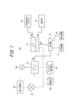
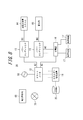
- FIG. 1 is a block diagram showing a schematic configuration of an energy management system according to the first embodiment of the present invention.
- the energy management system 10 according to the first embodiment of the present invention includes an energy management device 11, a smart meter 12, a power conditioner 13, a solar power generation system 14, a storage battery 15, a distribution board 16, and a load device 17.
- the solid line connecting the functional blocks represents the flow of power.
- a broken line connecting each functional block represents a control signal or a flow of information to be communicated.
- the communication indicated by the broken line may be wired communication or wireless communication.
- control signals and information including each layer.
- communication using a short-range communication method such as ZigBee (registered trademark) can be employed.
- various physical protocols such as ZigBee SEP2.0 (Smart Energy Profile 2.0), ECHONET Lite (registered trademark), etc. are given flexibility, and only the upper layer is provided.
- the specified communication protocol may be combined with a communication protocol that defines a physical layer such as WiFi (registered trademark) or PLC (Power Line Communication).
- the energy management system 10 loads the electric power supplied from the commercial power supply 50, the electric power generated by the solar power generation system 14, and the discharged electric power out of the electric power charged in the storage battery 15 via the distribution board 16. It can be supplied to the device 17.
- the energy management device 11 is an energy management device that manages the energy of one store, for example.
- the energy management device 11 manages the self-consumption ratio in the power generated by the solar power generation system 14 or manages the charge / discharge of the storage battery 15 via the power conditioner 13. Details of the function of the energy management apparatus 11 will be described later.
- the smart meter 12 is connected to the commercial power source 50 and measures the amount of power (demand power amount) supplied from the commercial power source 50.
- the smart meter 12 measures the power consumed by the load device 17 in the energy management system 10 (power consumption).
- the smart meter 12 can notify the energy management apparatus 11 of the measured electric energy.
- the power conditioner 13 converts direct current (DC) power supplied from the solar power generation system 14 and the storage battery 15 into alternating current (AC) power.
- the power conditioner 13 supplies the converted alternating-current power to each load device 17 through a branching system branched into a plurality by the distribution board 16.
- the power conditioner 13 can also sell the converted AC power to the power company via the distribution board 16 when there is a surplus in the power generated by the solar power generation system 14. Further, the power conditioner 13 can convert AC power supplied from the commercial power supply 50 into DC power for charging the storage battery 15.
- the solar power generation system 14 generates power using sunlight.
- the solar power generation system 14 includes a solar battery, and converts sunlight energy into DC power.
- the solar power generation system 14 assumes a mode in which, for example, a solar panel is installed on the roof of a house and power is generated using sunlight.
- the solar power generation system 14 can employ
- the photovoltaic power generation system 14 is under the jurisdiction of the energy management device 11, and the electric power generated by the photovoltaic power generation system 14 is converted into alternating current by the power conditioner 13 and then sent to each load device 17 as described above. It can be supplied and / or sold to a power company. Further, the storage battery 15 may be rechargeable by the power generated by the solar power generation system 14, and may be configured to be supplied to the load device 17 with a direct current.
- the storage battery 15 is under the jurisdiction of the energy management device 11 and can supply power to the load device 17 by discharging the charged power.
- the storage battery 15 can be charged with electric power supplied from the commercial power supply 50 or the solar power generation system 14. As shown in FIG. 1, the electric power discharged from the storage battery 15 can also be supplied to each load device 17 and the energy management device 11.
- the distribution board 16 branches the supplied power to a plurality of branches and distributes them to each load device 17.
- the number of load devices 17 connected to the energy management system 10 can be any number.
- the load device 17 is connected to the power conditioner 13 via the distribution board 16 and supplied with power.
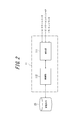
- FIG. 2 is a block diagram showing a schematic configuration of the energy management apparatus according to the first embodiment of the present invention.
- the energy management device 11 includes a communication unit 111 and a control unit 112.
- the communication unit 111 acquires information on the power consumption consumed by the load device 17 in the store or the like managed by the energy management system 10 from the smart meter 12. Note that the communication unit 111 may acquire power consumption information from a demand controller (not shown) outside the energy management apparatus 11.
- the control unit 112 stores the information on the power consumption acquired by the communication unit 111 in the storage medium 25.
- the storage medium 25 may be connected to the outside of the energy management apparatus 11 or may be built in the energy management apparatus 11.
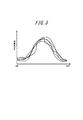
- FIG. 3 is an example in which the information on the power consumption acquired by the communication unit 111 is displayed by being overlapped for five days. As shown in FIG. 3, the power consumption in the energy management system 10 usually varies from day to day.
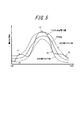
- FIG. 4 is an example of a graph in which the control unit 112 calculates an average value and a target range in a predetermined time period from data as shown in FIG.
- a solid line is an average value, and a broken line indicates an upper limit and a lower limit of the target range.
- the predetermined time period is a length of time used as a reference for determining an electric charge in a contract between a store managed by the energy management system 10 and the electric power company 60, for example, 30 minutes. .
- This time period is also referred to as a demand time period, and is a time length that serves as a basis for the basic charge.
- the monthly pay-as-you-go charge is also calculated based on the amount of power for each demand time period.
- the control unit 112 calculates a target range for each predetermined time period based on the statistical value of power consumption for a predetermined number of days in the past.
- a target range for each predetermined time period based on the statistical value of power consumption for a predetermined number of days in the past.
- the control unit 112 averages the power consumption data for a predetermined number of days in the past and calculates an average value. For example, the control unit 112 averages data for the last 14 days from 9:00 am to 9:30 am, and calculates an average value of power consumption in the time period from 9:00 am to 9:30 am To do. When the demand time period is 30 minutes, one day consists of 48 time periods. In this case, the control unit 112 calculates the average value for all the 48 time periods by the method described above.
- control unit 112 calculates the standard deviation from the power consumption data for a predetermined past number of days in each time period. For example, the control unit 112 calculates the standard deviation of the power consumption in the time period from 9 am to 9:30 am from the data for the latest 14 days from 9 am to 9:30 am.
- the control unit 112 calculates the upper limit of the target range in each time period using, for example, the following mathematical formula.
- P 1 is the upper limit of the target range of demand power amount
- sigma is the standard deviation of the energy consumption
- alpha is a predetermined coefficient.
- the predetermined coefficient ⁇ is a value determined so that charging / discharging can be secured within a range satisfying the specifications of the storage battery 15.
- the control unit 112 calculates the lower limit of the target range in each time period using, for example, the following mathematical formula.
- P 2 is the lower limit of the target range of demand power amount
- sigma is the standard deviation of the energy consumption
- beta is a predetermined coefficient.
- the predetermined coefficient ⁇ is a value determined so that charging / discharging can be secured within a range satisfying the specifications of the storage battery 15.
- the coefficient ⁇ may be the same value as ⁇ or a different value.
- the control unit 112 notifies the electric power provider 60 of data within the target range as a future predicted demand power amount, for example, a predicted demand power amount on the next day. For example, the control unit 112 can use the average value as the predicted demand power amount.
- the control unit 112 may notify the electric power provider 60 of the predicted demand power amount via the smart meter 12, or notify the electric power provider 60 of the predicted demand power amount via the network 70. Also good.
- the electric power company 60 collects the predicted electric power demand notified from a plurality of contracted users, and uses the electric power supply 60 of the general electric power company or the like as the electric power supplier 60 as a whole. The person in charge.
- the control unit 112 updates the target range every day. That is, when acquiring the new power consumption data for one day, the control unit 112 replaces the oldest one day of power consumption data with the new power consumption data, and sets the average value of the power consumption and the target range. Calculate the upper limit and the lower limit of the target range. Note that it is not essential for the control unit 112 to update the target range every day, and the update frequency may be adjusted as appropriate, such as updating every few days.
- the control unit 112 controls the storage battery 15 via the power conditioner 13 so that the actual amount of power demand does not deviate from the target range. Specifically, when the power consumption amount is likely to exceed the upper limit of the target range, the control unit 112 performs control so that the storage battery 15 is discharged, and reduces the power supplied from the commercial power supply 50. In addition, when the amount of power consumption is about to fall below the lower limit of the target range, the control unit 112 controls the storage battery 15 to be charged and increases the power supplied from the commercial power supply 50.
- FIG. 5 shows a state in which the control unit 112 controls the storage battery 15 so that the amount of power demand does not exceed the target range.
- control unit 112 discharges the storage battery 15 when indicated by A1, A2, and A3, that is, when the power consumption amount on the day is likely to exceed the upper limit of the target range.
- the amount of power demand received from the commercial power supply 50 is reduced.
- control unit 112 causes the storage battery 15 to be charged when indicated by B1 and B2 in FIG. 5, that is, when the power consumption of the day is likely to fall below the lower limit of the target range.
- the amount of power demand received from the commercial power source 50 is increased.
- the control unit 112 of the energy management device 11 controls the storage battery 15 in this way, so that the amount of power demand can be leveled so as to be within the target range.
- control unit 112 replaces or discharges the storage battery 15 with a ratio of turning the power generated by the solar power generation system 14 into private consumption. It may be increased. That is, the control unit 112 controls the power conditioner 13 so as to reduce the amount of power sold from the solar power generation system 14 to the power company and increase the usage amount of the load device 17.
- FIG. 6 is a graph of time on the horizontal axis and power consumption on the vertical axis.
- the horizontal axis shows from the start to the end of a certain demand period.
- the time at which the demand time period starts is referred to as the beginning of the demand time period
- the time at which the demand time period ends is referred to as the end time of the demand time period.
- FIG. 6 is an example when the demand time limit is 30 minutes, for example, a graph of 30 minutes from 9 am to 9:30 am. Note that the demand time limit of 30 minutes is merely an example, and is not limited to 30 minutes.
- the vertical axis indicates the power consumption within the demand time period, and the power consumption at the beginning of the demand time period is described as zero.
- the average value of the power consumption change rate shown in FIG. 6 is obtained by averaging a straight line connecting the power consumption amounts at the start and end of the demand time period for a predetermined number of days in the past (for example, 14 days).
- the control unit 112 calculates the average value of the change rate of the power consumption for all the time periods based on the data of the power consumption for a predetermined number of days in the past.
- the control unit 112 calculates the current rate of change of the power consumption from the short-time power consumption from the start of the demand time period to the predetermined time t0, and predicts the power consumption at the end of the demand time period.
- the current change rate of the power consumption amount is larger than the average value of the past change rates of the power consumption amount, and the predicted power consumption amount exceeds the upper limit of the target range.
- the control unit 112 performs control so that the storage battery 15 is discharged by the amount that the predicted power consumption exceeds the upper limit of the target range so that the demand power does not exceed the upper limit of the target range.
- control part 112 If the control part 112 is controlled so that the storage battery 15 is discharged, it will maintain the state which discharged the storage battery 15 until the end of the demand period.
- the control unit 112 continues to monitor the power consumption even after the predicted power consumption exceeds the upper limit of the target range and the storage battery 15 is controlled to be discharged. For example, as a result of discharging the storage battery 15, if the power consumption thereafter decreases more than expected and the power consumption is about to fall below the lower limit of the target range, the control unit 112 stops discharging the storage battery 15. .
- the control unit 112 calculates the current rate of change of the power consumption from the short-time power consumption from the start of the demand time period to the predetermined time t0, and predicts the power consumption at the end of the demand time period.
- the current rate of change in power consumption is smaller than the average value of the rate of change in past power consumption, and the predicted power consumption is below the lower limit of the target range.
- the control unit 112 controls the storage battery 15 to be charged as much as the predicted power consumption is below the lower limit of the target range so that the demand power does not fall below the lower limit of the target range.
- control part 112 If the control part 112 is controlled to charge the storage battery 15, it will maintain the state which charges the storage battery 15 until the end of a demand time limit.
- the control unit 112 continues to monitor the power consumption even after the predicted power consumption is below the lower limit of the target range and the storage battery 15 is controlled to be charged. For example, as a result of charging the storage battery 15, when the subsequent power consumption increases more than expected and the demand power amount is likely to exceed the upper limit of the target range, the control unit 112 stops charging the storage battery 15. .
- the control unit 112 assumes that the rate of change of the power consumption from the start of the demand time period to the time t0 continues until the end of the demand time period, and the consumption at the end of the demand time period.
- the amount of power is predicted, the method of predicting the amount of power consumption is not limited to this.
- the control unit 112 may predict the power consumption amount at the end of the demand time period by approximating the power consumption amount at more measurement points with a higher-order function.
- the control unit 112 predicts the power consumption at the end of the demand period with the slope of the time from the start of the demand period to the time t0. Is an example and is not limited to this.
- the control unit 112 may predict the power consumption amount using data on the power consumption amount for the time period prior to the start of the demand time period. Specifically, for example, when predicting the power consumption from 9:00 to 9:30, the control unit 112 uses the data on the power consumption from 8:30 to 9:00 or the earlier demand time limit. You may predict using the data of power consumption of.
- the control unit 112 of the energy management device 11 controls the storage battery 15 in this way, so that the amount of power demand can be leveled so as to be within the target range.
- the energy management apparatus 11 calculates the target range of the future predicted demand power amount for each predetermined time period based on the statistical value of the power consumption amount for a predetermined number of days. Therefore, it is possible to accurately predict the future demand power amount from the past power consumption amount.
- the power provider 60 is notified of the predicted demand power amount accurately predicted from the energy management device 11 of each contracting consumer, the future power demand amount of the power business operator 60 as a whole. Can be accurately predicted, and power can be supplied at low cost from a power supplier such as a general electric utility.
- the power supplier 60 can receive power supply from the power supplier at a low cost, as a result, the customer is more likely to be able to make a contract with the power supplier under favorable conditions. It can be expected to reduce power costs.
- the power demand 60 is notified of the predicted demand power amount accurately predicted because it is easy to make a power generation plan.
- the energy management device 11 can set an appropriate target range by calculating the upper limit of the target range by adding a value obtained by multiplying the standard deviation by a predetermined coefficient to the average value.
- the energy management device 11 can set an appropriate target range by subtracting a value obtained by multiplying the standard deviation by a predetermined coefficient from the average value and calculating the lower limit of the target range.
- the energy management device 11 controls the charging / discharging of the storage battery 15 under the jurisdiction of the energy management device 11 so that the power consumption does not fall outside the target range, thereby reducing the variation in the daily demand power amount in the same time zone. As a result, the amount of power demand can be easily grasped.
- the energy management device 11 when the energy management device 11 is likely to exceed the upper limit of the target range, the energy management device 11 discharges the storage battery 15, and when the energy consumption is likely to fall below the lower limit of the target range, the storage battery 15 is charged. As a result, it is possible to suppress variations in daily power demand in the same time zone, and to easily grasp the power demand.
- the energy management device 11 controls the photovoltaic power generation system 14 under the jurisdiction of the energy management device 11 so that the demand power amount does not fall outside the target range, thereby reducing the variation in the daily demand power amount in the same time zone. As a result, the amount of power demand can be easily grasped.
- the energy management device 11 when the energy management device 11 is likely to exceed the upper limit of the target range, the energy management device 11 increases the self-consumption ratio in the electric power generated by the solar power generation system 14 to increase the daily demand power in the same time zone. The variation in the amount can be suppressed, and the amount of power demand can be easily grasped.
- the energy management device 11 calculates the target range of the future predicted demand power amount and controls the storage battery 15 so that the demand power amount does not deviate from the target range. Variations in daily power demand can be suppressed.
- the power provider 60 has a variation in the demand power amount as a whole of the power provider 60.
- the power supply can be received at low cost from a power supplier such as a general electric utility.
- the power supplier 60 can receive power supply from the power supplier at a low cost, as a result, the customer is more likely to be able to make a contract with the power supplier under favorable conditions. It can be expected to reduce power costs.
- the electric power provider 60 it is preferable for the electric power provider 60 to suppress variations in daily demand power amount in the same time zone because it is easy to make a power generation plan.
- the energy management device 11 calculates a past average value of the rate of change of the power consumption for each predetermined time period from the power consumption for a predetermined number of days, and the power consumption for a short time immediately after the start of each time period From the above, the current rate of change in power consumption is calculated, and the storage battery 15 is controlled so as not to deviate from the target range based on the rate of change in power consumption in each time period. Variations in the amount of power can be suppressed, and the amount of power demand can be easily grasped.
- the energy management device 11 discharges the storage battery 15 when the current rate of change is larger than the average value of the past rate of change and the amount of power demand is likely to exceed the upper limit of the target range, and the current rate of change is When the demand power amount is likely to be below the lower limit of the target range, the variation in demand power amount for each day in the same time zone can be suppressed by charging the storage battery 15. The amount of power can be easily grasped.
- the system configuration is based on the assumption that surplus power among the power generated by the solar power generation system 14 is sold to an electric power company has been described as an example.
- Other system configurations may be adopted. That is, as shown in FIG. 8, it is preferable to similarly charge and discharge the storage battery 15 even in the case of a system configuration corresponding to the total purchase system.
- FIG. 9 is a block diagram showing a schematic configuration of an energy management system according to the second embodiment of the present invention.
- the energy management system 30 according to the second embodiment of the present invention includes an energy management device 11, a smart meter 12, a power storage device 18, a distribution board 16, and a load device 17.
- the power storage device 18 includes a power conditioner 13 and a storage battery 15.
- the energy management system 30 can supply the discharged power out of the power charged in the storage battery 15 to the load device 17 via the distribution board 16 in addition to the power supplied from the commercial power supply 50.
- the energy management device 11 is an energy management device that manages the energy of one store, for example.
- the energy management device 11 manages charging / discharging of the storage battery 15 via the power conditioner 13. Details of the function of the energy management apparatus 11 will be described later.
- the power storage device 18 includes a power conditioner 13 and a storage battery 15.
- the power storage device 18 is illustrated as a device outside the housing of the energy management device 11, but the power storage device 18 may be included in the housing of the energy management device 11.
- the power conditioner 13 converts direct current (DC) power supplied from the storage battery 15 into alternating current (AC) power.
- the power conditioner 13 supplies the converted alternating-current power to each load device 17 through a branching system branched into a plurality by the distribution board 16.
- the power conditioner 13 can convert AC power supplied from the commercial power supply 50 into DC power for charging the storage battery 15.
- the storage battery 15 is under the jurisdiction of the energy management device 11 and can supply power to the load device 17 by discharging the charged power.
- the storage battery 15 can be charged with electric power supplied from the commercial power supply 50. As shown in FIG. 9, the electric power discharged from the storage battery 15 can also be supplied to each load device 17.
- FIG. 10 is a block diagram showing a schematic configuration of the energy management device according to the second embodiment of the present invention.
- the energy management device 11 includes an acquisition unit 113 and a control unit 112.
- the acquisition unit 113 acquires the characteristic information of the storage battery 15 via the power conditioner 13.
- the characteristic information of the storage battery 15 includes rated output information and capacity information of the storage battery 15.
- the acquisition unit 113 includes a communication unit, and when the power storage device 18 is provided outside the casing of the energy management device 11, the communication unit communicates with the power conditioner 13 of the power storage device 18.
- the acquisition unit 113 acquires information on the power consumption consumed by the load device 17 in the store or the like managed by the energy management system 30 from the smart meter 12.
- the control unit 112 stores the information on the power consumption acquired by the acquisition unit 113 in the storage medium 25.
- the storage medium 25 may be connected to the outside of the energy management apparatus 11 or may be built in the energy management apparatus 11.
- the control unit 112 controls the storage battery 15 via the power conditioner 13 to discharge or charge the storage battery 15.
- the electricity price contract between the specific scale electric power company 220 and the power supplier 210 is made based on a predetermined reference time length.
- the predetermined reference time length is also called a demand time period, and is, for example, in units of 30 minutes.
- the demand time period is a time length that serves as a basis for the basic fee, and the monthly pay-as-you-go fee is also calculated based on the electric energy for each demand time period.
- the amount of power in the demand time period is handled in units of the minimum amount of power determined by the power supplier 210.
- the minimum power unit is, for example, 1 kWh.
- the demand time period for example, even if the amount of power demand less than 1 kWh is reduced, there is a case where the effect of reducing the amount of power does not appear on the contract.
- the minimum power amount unit is 1 kWh, so both are 55 kWh. Are treated as Therefore, even if the amount of power is reduced, it is not reflected in the charge.
- the amount of power more than the minimum power amount unit for example, 1 kWh
- the control unit 112 discharges at least the minimum electric energy unit (for example, 1 kWh) in the electricity rate calculation determined by the electric power company 60 during the reference time length. Or the storage battery 15 is controlled so that it can be charged. This is shown in FIG.
- FIG. 11A shows an example in which the acquisition unit 113 acquires the rated output information of the storage battery 15 from the storage battery 15 and the result is 2.5 kW.
- the control unit 112 needs to discharge the storage battery 15 for 24 minutes as a discharge time in order to discharge the storage battery 15 by 1 kWh which is the minimum unit of electric power based on the acquired rated output information of 2.5 kW. Calculate that there is. Subsequently, in order to discharge only 1 kWh which is the minimum electric energy unit, the control unit 112 calculates backward from the end point of the reference time length of 30 minutes (30 minutes to 24 minutes), and starts from the start point of the reference time length. It is calculated that the storage battery 15 needs to be discharged before the minute elapses. Based on this result, the control unit 112 determines whether or not to discharge the storage battery 15 before 6 minutes have elapsed from the starting point of the reference time length.
- FIG. 11B shows an example in which the acquisition unit 113 acquires the rated output information of the storage battery 15 from the storage battery 15 and the result is 5 kW.
- the control unit 112 needs to discharge for 12 minutes as a discharge time in order to discharge the storage battery 15 by 1 kWh which is the minimum unit of electric power based on the acquired rated output information of 5 kW. Is calculated. Subsequently, in order to discharge only 1 kWh which is the minimum unit of electric energy, the control unit 112 performs a reverse calculation from 30 minutes which is the end point of the reference time length (30 minutes to 12 minutes), and 18 from the start point of the reference time length. It is calculated that the storage battery 15 needs to be discharged before the minute elapses. Based on this result, the control unit 112 determines whether or not to discharge the storage battery 15 before 18 minutes have elapsed from the starting point of the reference time length.
- FIG. 11 shows an example in which the control unit 112 discharges the storage battery 15 by 1 kWh, which is the minimum power amount unit, but only an integral multiple of the power amount such as twice or three times the minimum power amount unit. Even when the storage battery 15 is discharged, it is possible to calculate how many minutes it is necessary to discharge the storage battery 15 before a lapse of the reference time length by a similar method.
- control part 112 considers the rated output of the some storage battery 15 whole. It is possible to calculate how many minutes have elapsed from the starting point of the reference time length before the storage battery 15 needs to be discharged.
- the energy management device 11 calculates the discharge time necessary for the storage battery 15 to discharge the minimum unit of electric power from the characteristic information of the storage battery 15, and the reference time length ( In order to determine whether or not to discharge the storage battery 15 from the end point of the demand time period until the time calculated by calculating the discharge time has elapsed, when the demand power amount is reduced in the demand time period, the minimum power amount unit The amount of power described above can be reduced. Thereby, the energy management apparatus 11 can contribute to a favorable power supply-demand balance maintenance by reducing the dispersion
- the case where the storage battery is controlled so that the demand power amount does not deviate from the target range has been described as an example.
- the contract form with the power provider is a simple pay-per-use charge, and the amount of power used
- the present invention can also be applied to a case where it is simply desired to reduce the above.
Abstract
過去の消費電力量から、今後の需要電力量を精度良く予測する。 本発明に係るエネルギー管理装置10は、消費電力量の情報を取得する通信部111と、消費電力量の情報に基づいて、電力事業者に通知する今後の予測需要電力量の目標範囲を算出する制御部112とを備え、制御部112は、所定の日数分の消費電力量の統計値に基づいて、所定の時限毎に目標範囲を算出する。
Description
本出願は、日本国特許出願2013-178032号(2013年8月29日出願)、日本国特許出願2013-178069号(2013年8月29日出願)及び日本国特許出願2013-184363号(2013年9月5日出願)の優先権を主張するものであり、当該出願の開示全体を、ここに参照のために取り込む。
本発明は、同一時間帯における日毎の需要電力量のばらつきを抑えるエネルギー管理装置、エネルギー管理方法及びエネルギー管理システムに関するものである。
近年、電力小売事業について、多様な形態が存在する。例えば日本においては、かつては一般電気事業者により独占されていたが、改正電気事業法の施行により、電力小売の自由化が一部認められるようになった。
例えば、特定規模電気事業者(PPS:Power Producer and Supplier)は、契約電力が50kW以上の大口の需用者に対して電力を小売することを認められている。大口の需用者にとっては、有利な条件で契約できる電気事業者を選択することにより、電力コストを下げることができるというメリットがある。特定規模電気事業者に関連しては、低コスト化に関する様々な発明が提案されている(例えば、特許文献1参照)。
図12は、特的規模電気事業者が需用者に対して電力を供給する様子を概念的に示す図である。特定規模電気事業者220は、電力供給者210から電力の供給を受ける。ここで、電力供給者は、一般電気事業者などの発電設備を有する事業者である。
特定電気事業者220は、送配電ネットワーク230を経由して、電力供給者210から供給された電力を、契約している需用者240に供給する。ここで、送配電ネットワーク230は、通常、一般電気事業者によって管理されている。
電力供給者210は、必要な発電量を見積もって発電計画を立てる必要があるため、特定規模電気事業者220に対し、例えば30分単位の需要電力量の予測値の1日分を予め通知するよう要求している。
特定規模電気事業者220は、電力供給者210から実際に供給を受けた電力量(需要電力量)が、予測需要電力量に近い場合(例えば±3%以内)は、電力供給者210から低コストで電力を購入することができる(すなわちインバランス料金を比較的低額とすることができる)。一方、例えば、需要電力量が予測需要電力量より3%以上大きくなってしまった場合は、電力供給者210はペナルティーとして電力販売価格を高額なものとするため、特定規模電気事業者220は、予測需要電力量を超えた分の電力量について高額なインバランス料金が発生してしまうこととなる。
ところで、需要電力量が予測需要電力量より小さく、余剰分が発生する場合には、その余剰分が予測需要電力量の3%以内の場合には、その余剰分を電力供給者210は一定水準の価格で買い取る。ところが、余剰分が予測需要電力量の3%以上と大きい場合には、その余剰分を電力供給者210が引き取るにあたり、買取料金は設定されない。すなわち無料で回収される。したがって、特定規模電気事業者220にとっては、単に需要電力量を減らすのではなく、需要電力量を予測需要電力量に近づけることが好ましい。
電力供給者210が、需要電力量が予測需要電力量に近い場合に比較的低額なインバランス料金を設定しているのは、電力供給者210から見ても発電計画が立てやすくなるなどのメリットがあることによる。よって、特定規模電気事業者220は、予測需要電力量に近い範囲の需要電力量で運営する実績を積むと、予測値の信憑性が向上し、電力供給者210による発電計画の精度を高くすることができる。したがって、予測需要電力量に近い範囲の需要電力量で運営する実績を積むと、電力供給者210へのインバランス料金を低下させることも可能となる。
特定規模電気事業者220は、電力供給者210へのインバランス料金を抑えるためには、翌日の需要電力量を精度良く予測する必要がある。しかしながら、同一時間帯における日毎の消費電力量のばらつきは大きく、過去の消費電力量から精度の良い予測をすることは困難であった。
また、特定規模電気事業者220が電力供給者210に通知する予測需要電力量の精度が悪く、電力供給者210へのインバランス料金が高コストとなると、結果的に、需用者240が特定規模電気事業者220から電力を購入する料金も高くなってしまう可能性が高いという問題があった。
また、同一時間帯における日毎の消費電力量のばらつきが大きいと、予想需要電力量と実際の需要電力量との差が、特定規模電気事業者220がインバランス料金が安価に済む範囲を超える可能性が高くなり、特定規模電気事業者220が電力供給者210へ支払うインバランス料金が高価になり、結果的に、コストが高くなる可能性が高いという問題があった。
したがって、かかる点に鑑みてなされた本発明の目的は、過去の消費電力量から、今後の需要電力量を精度良く予測することができるエネルギー管理装置、エネルギー管理方法及びエネルギー管理システムを提供することにある。
また、本発明の目的は、予想需要電力量と実際の需要電力量との差を小さくすることができるエネルギー管理装置、エネルギー管理方法及びエネルギー管理システムを提供することにある。
また、本発明の目的は、日毎の消費電力量のばらつきを低減させることにより良好な電力需給バランス維持に貢献するエネルギー管理装置、エネルギー管理方法及びエネルギー管理システムを提供することにある。
上記課題を解決するため、本発明に係るエネルギー管理装置は、消費電力量の情報を取得する通信部と、前記消費電力量の情報に基づいて、電力事業者に通知する今後の予測需要電力量の目標範囲を算出する制御部とを備え、前記制御部は、所定の日数分の前記消費電力量の統計値に基づいて、所定の時限毎に前記目標範囲を算出することを特徴とするものである。
また、本発明に係るエネルギー管理装置において、前記所定の時限は、前記電力事業者との間で電気料金決定の基準となる時間長であることが好ましい。
また、本発明に係るエネルギー管理装置において、前記所定の時限は、前記電力事業者との間で月次の従量連動料金とは別途設定される基本料金の基準となる時間長であることが好ましい。
また、本発明に係るエネルギー管理装置において、前記制御部は、標準偏差に所定の係数を乗算した値を平均値に加算して前記目標範囲の上限を算出することが好ましい。
また、本発明に係るエネルギー管理装置において、前記制御部は、標準偏差に所定の係数を乗算した値を平均値から減算して前記目標範囲の下限を算出することが好ましい。
また、本発明に係るエネルギー管理装置において、前記制御部は、需要電力量が前記目標範囲から外れないよう、前記エネルギー管理装置の管轄下の蓄電池の充放電を制御することが好ましい。
また、本発明に係るエネルギー管理装置において、前記制御部は、所定の日数分の前記消費電力量から、前記所定の時限毎における消費電力量の変化率の過去の平均値を算出し、各時限の開始直後の短期間の消費電力量から、消費電力量の現在の変化率を算出し、各時限における消費電力量の変化率に基づいて、前記目標範囲から外れないように蓄電池を制御することが好ましい。
また、本発明に係るエネルギー管理装置において、前記制御部は、各時限において、現在の変化率が過去の変化率の平均値より大きく、需要電力量が前記目標範囲の上限を上回りそうな場合に、前記蓄電池を放電させることが好ましい。
また、本発明に係るエネルギー管理装置において、前記制御部は、各時限において、現在の変化率が過去の変化率の平均値より小さく、需要電力量が前記目標範囲の下限を下回りそうな場合に、前記蓄電池を充電することが好ましい。
また、本発明に係るエネルギー管理装置において、前記制御部は、前記所定の時限単位で放電又は充電を切り換えることが好ましい。
また、本発明に係るエネルギー管理装置において、前記制御部は、前記蓄電池を放電させた結果、需要電力量が前記目標範囲の下限を下回りそうになった場合は、前記蓄電池の放電を停止することが好ましい。
また、本発明に係るエネルギー管理装置において、前記制御部は、前記蓄電池を充電させた結果、需要電力量が前記目標範囲の上限を上回りそうになった場合は、前記蓄電池の充電を停止することが好ましい。
また、本発明に係るエネルギー管理装置において、前記制御部は、前記消費電力量の情報として、前記エネルギー管理装置外のデマンドコントローラにて用いられるデータを利用することが好ましい。
また、本発明に係るエネルギー管理装置において、前記制御部は、需要電力量が前記目標範囲から外れないよう、前記エネルギー管理装置の管轄下の太陽光発電システムを制御することが好ましい。
また、本発明に係るエネルギー管理装置において、前記制御部は、消費電力量が前記目標範囲の上限を上回りそうな場合は、前記太陽光発電システムが発電した電力における自家消費割合を増加させることが好ましい。
また、本発明に係るエネルギー管理装置において、蓄電池の特性情報を取得する取得部をさらに備え、前記制御部は、前記蓄電池の前記特性情報から、電気料金算出における電力事業者が定めた最小の電力量単位を前記蓄電池が放電するために必要となる放電時間を算出し、前記基準時間長の監視を行う際、当該基準時間長の終点から前記放電時間を逆算した時間が経過するまでに、当該監視の時間長における前記蓄電池の放電を行うか否かを決定することが好ましい。
また、本発明に係るエネルギー管理装置において、前記取得部は、前記エネルギー管理装置外に設けられ前記蓄電池を備える蓄電装置と通信を行う通信部を有することが好ましい。
また、本発明に係るエネルギー管理装置において、前記通信部は、前記蓄電装置の有するパワーコンディショナを経由して、前記蓄電池の特性情報を取得することが好ましい。
また、本発明に係るエネルギー管理装置において、前記通信部は、前記蓄電池の定格出力情報を前記特性情報として取得することが好ましい。
また、本発明に係るエネルギー管理装置において、前記通信部は、ECHONET Liteプロトコルを用いて前記定格出力情報を取得することが好ましい。
また、本発明に係るエネルギー管理装置において、前記基準時間長は、前記電力事業者との間で月次の従量連動料金とは別途設定される基本料金の基準となる時間長であることが好ましい。
また、本発明に係るエネルギー管理装置において、前記基準時間長は、前記電力事業者との間で高圧受電者向けの契約において定められるデマンド時限であることが好ましい。
また、本発明に係るエネルギー管理装置において、前記最小の電力量単位は1kWhであることが好ましい。
また、上記課題を解決するため、本発明に係るエネルギー管理方法は、消費電力量の情報を取得するステップと、所定の日数分の前記消費電力量の統計値に基づいて、電力事業者に通知する今後の予測需要電力量の目標範囲を所定の時限毎に算出するステップとを含むものである。
また、上記課題を解決するため、本発明に係るエネルギー管理システムは、エネルギー管理装置と蓄電池とを備えるエネルギー管理システムであって、前記エネルギー管理装置は、消費電力量の情報を取得する通信部と、前記消費電力量の情報に基づいて、電力事業者に通知する今後の予測需要電力量から目標範囲を算出する制御部とを備え、前記制御部は、所定の日数分の前記消費電力量の統計値に基づいて、所定の時限毎に前記目標範囲を算出し、需要電力量が前記目標範囲から外れないように前記蓄電池を制御することを特徴とするものである。
本発明によれば、過去の消費電力量から、今後の需要電力量を精度良く予測することができる。
また、本発明によれば、予想需要電力量と実際の需要電力量との差を小さくすることができる。
また、本発明によれば、日毎の消費電力量のばらつきを低減させることにより、良好な電力需給バランス維持に貢献することができる。
以下、本発明に係る実施形態について説明する。
[第1実施形態]
まず、本発明の第1実施形態に係るエネルギー管理システムの概要について説明する。本発明の第1実施形態に係るエネルギー管理システムは、需用者が、例えば一つの店舗においてエネルギーを管理するためのエネルギー管理システムである。後述する図1の電力事業者60は、例えば、特定規模電気事業者に相当するものである。図1の商用電源50は、電力事業者60(特定規模電気事業者)が、一般電気事業者などの電力供給者から購入し、一般電気事業者が管理する送配電ネットワークを経由して需用者に供給している電力を表すものである。
まず、本発明の第1実施形態に係るエネルギー管理システムの概要について説明する。本発明の第1実施形態に係るエネルギー管理システムは、需用者が、例えば一つの店舗においてエネルギーを管理するためのエネルギー管理システムである。後述する図1の電力事業者60は、例えば、特定規模電気事業者に相当するものである。図1の商用電源50は、電力事業者60(特定規模電気事業者)が、一般電気事業者などの電力供給者から購入し、一般電気事業者が管理する送配電ネットワークを経由して需用者に供給している電力を表すものである。
図1は、本発明の第1実施形態に係るエネルギー管理システムの概略構成を示すブロック図である。本発明の第1実施形態に係るエネルギー管理システム10は、エネルギー管理装置11、スマートメータ12、パワーコンディショナ13、太陽光発電システム14、蓄電池15、分電盤16及び負荷機器17を備える。
図1において、各機能ブロックを結ぶ実線は、電力の流れを表す。また、図1において、各機能ブロックを結ぶ破線は、制御信号又は通信される情報の流れを表す。当該破線が示す通信は有線通信としてもよいし、無線通信としてもよい。
制御信号及び情報の通信には、各階層含め、様々な方式を採用可能である。例えば、エネルギー管理装置11と、スマートメータ12及びパワーコンディショナ13との通信には、ZigBee(登録商標)などの近距離通信方式による通信を採用することができる。また、物理層を含む下位の層の上で、各種プロトコル、例えばZigBee SEP2.0(Smart Energy Profile 2.0)、ECHONET Lite(登録商標)などのような物理層に自由度をもたせ、上位層だけを規定した通信プロトコルと、WiFi(登録商標)あるいはPLC(Power Line Communication)のような物理層が規定される通信プロトコルとを組み合わせて動作させてもよい。
エネルギー管理システム10は、商用電源50から供給される電力の他、太陽光発電システム14が発電する電力、蓄電池15に充電された電力のうち放電された電力を、分電盤16を介して負荷機器17に供給可能である。
エネルギー管理装置11は、例えば、一店舗のエネルギーを管理するエネルギー管理装置である。エネルギー管理装置11は、パワーコンディショナ13を介して、太陽光発電システム14が発電した電力における自家消費割合を管理したり、蓄電池15の充放電を管理したりする。エネルギー管理装置11の機能についての詳細は後述する。
スマートメータ12は、商用電源50に接続されて、商用電源50から供給される電力量(需要電力量)を計測する。また、スマートメータ12は、エネルギー管理システム10内の負荷機器17などによって消費される電力(消費電力量)を計測する。スマートメータ12は、計測した電力量を、エネルギー管理装置11に通知可能である。
パワーコンディショナ13は、太陽光発電システム14及び蓄電池15から供給される直流(DC)の電力を、交流(AC)の電力に変換する。パワーコンディショナ13は、変換した交流の電力を、分電盤16で複数に分岐した支幹を介して各負荷機器17に供給する。
また、パワーコンディショナ13は、太陽光発電システム14が発電した電力に余剰がある場合には、変換した交流の電力を、分電盤16を介して電力会社に売電することもできる。また、パワーコンディショナ13は、商用電源50から供給される交流の電力を、蓄電池15に充電するための直流の電力に変換可能である。
太陽光発電システム14は、太陽光を利用して発電する。このため、太陽光発電システム14は、太陽電池を備えており、太陽光のエネルギーを直流の電力に変換する。本実施形態において、太陽光発電システム14は、例えば家の屋根などにソーラパネルを設置して、太陽光を利用して発電するような態様を想定している。しかしながら、本発明において、太陽光発電システム14は、太陽光のエネルギーを電力に変換できるものであれば、任意のものを採用することができる。
太陽光発電システム14は、エネルギー管理装置11の管轄下にあり、太陽光発電システム14が発電する電力は、上述したように、パワーコンディショナ13によって交流に変換されてから、各負荷機器17へ供給、及び/又は、電力会社に売電可能である。また、太陽光発電システム14が発電した電力により、蓄電池15が充電可能であってもよく、さらには直流のまま負荷機器17に供給される構成であってもよい。
蓄電池15は、エネルギー管理装置11の管轄下にあり、充電された電力を放電することにより、負荷機器17に電力を供給可能である。また、蓄電池15は、商用電源50又は太陽光発電システム14等から供給される電力を充電可能である。図1に示すように、蓄電池15から放電される電力も、各負荷機器17及びエネルギー管理装置11に供給可能である。
分電盤16は、供給された電力を複数の支幹に分岐させて各負荷機器17に分配する。
図1において、エネルギー管理システム10に接続される負荷機器17は、任意の数とすることができる。負荷機器17は分電盤16を介してパワーコンディショナ13に接続されて、電力が供給される。
次に、エネルギー管理装置11の動作について具体的に説明する。図2は、本発明の第1実施形態に係るエネルギー管理装置の概略構成を示すブロック図である。エネルギー管理装置11は、通信部111と、制御部112とを備える。
通信部111は、エネルギー管理システム10が管理する店舗などにおいて負荷機器17によって消費されている消費電力量の情報を、スマートメータ12から取得する。なお、通信部111は、エネルギー管理装置11の外部にある図示しないデマンドコントローラから消費電力量の情報を取得してもよい。
制御部112は、通信部111が取得した消費電力量の情報を、記憶媒体25に記憶させる。記憶媒体25は、エネルギー管理装置11の外部に接続されるようにしてもよいし、エネルギー管理装置11に内蔵されるようにしてもよい。
図3は、通信部111が取得した消費電力量の情報を、5日分重ねて表示した例である。図3に示されるように、通常、エネルギー管理システム10内における消費電力量は、日毎にばらつく。
図4は、制御部112が、図3に示したようなデータから、所定の時限における、平均値及び目標範囲を算出したグラフの例である。実線は平均値であり、破線は目標範囲の上限及び下限を示している。
ここで、所定の時限とは、エネルギー管理システム10が管理する店舗と電力事業者60との契約において、電気料金決定の基準となる時間長であり、例えば30分などを単位とするものである。この時限はデマンド時限とも称され、基本料金の基準となる時間長であり、また、月次の従量連動料金も、デマンド時限毎の電力量に基づいて算出される。
制御部112は、過去の所定の日数分の消費電力量の統計値に基づいて、所定の時限毎に目標範囲を算出する。以下、算出方法の一例を具体的に説明する。
制御部112は、各時限において、過去の所定の日数分の消費電力量のデータを平均して、平均値を算出する。制御部112は、例えば、午前9時から午前9時30分までの直近14日分のデータを平均して、午前9時から午前9時30分までの時限における消費電力量の平均値を算出する。デマンド時限が30分である場合、1日は48時限からなるが、この場合、制御部112は、48時限の全てについて、上述の方法で平均値を算出する。
また、制御部112は、各時限において、過去の所定の日数分の消費電力量のデータから標準偏差を算出する。制御部112は、例えば、午前9時から午前9時30分までの直近14日分のデータから、午前9時から午前9時30分までの時限における消費電力量の標準偏差を算出する。
制御部112は、各時限において、例えば、以下のような数式により、目標範囲の上限を算出する。
上記数式(1)において、P1は需要電力量の目標範囲の上限値、Paは消費電力量の平均値、σは消費電力量の標準偏差、αは所定の係数である。所定の係数αは、蓄電池15の仕様を満たす範囲内で充放電が確保できるように決められる値である。
制御部112は、各時限において、例えば、以下のような数式により、目標範囲の下限を算出する。
上記数式(2)において、P2は需要電力量の目標範囲の下限値、Paは消費電力量の平均値、σは消費電力量の標準偏差、βは所定の係数である。所定の係数βは、蓄電池15の仕様を満たす範囲内で充放電が確保できるように決められる値である。係数βは、αと同じ値であってもよいし異なる値であってもよい。
制御部112は、目標範囲の範囲内のデータを、今後の予測需要電力量、例えば、翌日の予測需要電力量として、電力事業者60に通知する。制御部112は、例えば平均値を予測需要電力量とすることができる。
制御部112は、スマートメータ12を経由して、電力事業者60に予測需要電力量を通知してもよいし、ネットワーク70を経由して、電力事業者60に予測需要電力量を通知してもよい。なお、電力事業者60は、契約している複数の需用者から通知された予測需要電力量をまとめて、電力事業者60全体としての予測需要電力量を、一般電気事業者などの電力供給者に通知する。
制御部112は、目標範囲を毎日更新する。すなわち、制御部112は、1日分の新しい消費電力量データを取得すると、最も古い1日分の消費電力量データを新しい消費電力量データに置き換えて、消費電力量の平均値、目標範囲の上限及び目標範囲の下限を算出する。なお、制御部112が、目標範囲を毎日更新することは必須ではなく、数日おきに更新するなど、更新頻度は適宜調整してもよい。
制御部112は、目標範囲を算出すると、実際の需要電力量が目標範囲から外れないように、パワーコンディショナ13を介して蓄電池15を制御する。具体的には、制御部112は、消費電力量が目標範囲の上限を上回りそうになると、蓄電池15を放電させるように制御して、商用電源50から供給を受ける電力を減らす。また、制御部112は、消費電力量が目標範囲の下限を下回りそうになると、蓄電池15を充電させるように制御して、商用電源50から供給を受ける電力を増やす。
図5に、制御部112が、需要電力量が目標範囲を超えないように蓄電池15を制御する様子を示す。
制御部112は、図5において、A1、A2及びA3で示しているようなとき、すなわち、当日の消費電力量が目標範囲の上限を上回りそうになっている場合は、蓄電池15を放電させて、商用電源50から供給を受ける需要電力量を減少させる。
また、制御部112は、図5において、B1及びB2で示しているようなとき、すなわち、当日の消費電力量が目標範囲の下限を下回りそうになっている場合は、蓄電池15を充電させて、商用電源50から供給を受ける需要電力量を増加させる。
エネルギー管理装置11の制御部112が、このように蓄電池15を制御することにより、需要電力量が目標範囲内に収まるように平準化することができる。
また、制御部112は、消費電力量が目標範囲の上限を上回りそうな場合、蓄電池15を放電させる代わり、あるいは放電に加えて、太陽光発電システム14が発電した電力を自家消費に回す割合を増加させてもよい。すなわち制御部112は、太陽光発電システム14からの電力会社への売電量を下げ、負荷機器17での使用量を上げるようパワーコンディショナ13を制御する。
図6は、横軸が時間、縦軸が消費電力量のグラフである。横軸は、あるデマンド時限の開始から終了までを示している。以下、デマンド時限が開始する時間をデマンド時限の始期、デマンド時限が終了する時間をデマンド時限の終期と称する。図6は、デマンド時限が30分の場合の例であり、例えば、午前9時から午前9時30分までの30分間のグラフである。なお、デマンド時限を30分としたのは、あくまでも一例であり、30分に限るものではない。
縦軸は、デマンド時限内における消費電力量を示し、デマンド時限の始期の消費電力量を0として記載したものである。
図6に示す消費電力量の変化率の平均値は、デマンド時限の始期と終期における消費電力量を結んだ直線を、過去の所定の日数分(例えば、14日間)について平均したものである。制御部112は、過去の所定の日数分の消費電力量のデータに基づいて、全ての時限について、消費電力量の変化率の平均値を算出する。
制御部112は、デマンド時限の始期から所定の時刻t0までの短期間の消費電力量から、消費電力量の現在の変化率を算出し、デマンド時限の終期における消費電力量を予測する。図6に示す例においては、消費電力量の現在の変化率が過去の消費電力量の変化率の平均値より大きく、予測消費電力量が目標範囲の上限を上回っている。この場合、制御部112は、需要電力量が目標範囲の上限を上回らないように、予測消費電力量が目標範囲の上限を上回っている分だけ、蓄電池15を放電させるように制御する。
制御部112は、蓄電池15を放電させるように制御すると、デマンド時限の終期まで、蓄電池15を放電させた状態を維持する。
制御部112は、予測消費電力量が目標範囲の上限を上回り、蓄電池15を放電させる制御をした後も、消費電力量の監視を続ける。例えば、蓄電池15を放電させた結果、その後の消費電力量が予測以上に減り、消費電力量が目標範囲の下限を下回りそうになった場合は、制御部112は、蓄電池15の放電を停止させる。
続いて、図7を参照して、当日の消費電力量が目標範囲の下限を下回りそうになっている場合に、制御部112が蓄電池15を充電させる制御をする動作の一例を説明する。
制御部112は、デマンド時限の始期から所定の時刻t0までの短期間の消費電力量から、消費電力量の現在の変化率を算出し、デマンド時限の終期における消費電力量を予測する。図7に示す例においては、消費電力量の現在の変化率が過去の消費電力量の変化率の平均値より小さく、予測消費電力量が目標範囲の下限を下回っている。この場合、制御部112は、需要電力量が目標範囲の下限を下回らないように、予測消費電力量が目標範囲の下限を下回っている分だけ、蓄電池15を充電させるように制御する。
制御部112は、蓄電池15を充電させるように制御すると、デマンド時限の終期まで、蓄電池15を充電させる状態を維持する。
制御部112は、予測消費電力量が目標範囲の下限を下回り、蓄電池15を充電させる制御をした後も、消費電力量の監視を続ける。例えば、蓄電池15を充電させた結果、その後の消費電力量が予測以上に増え、需要電力量が目標範囲の上限を上回りそうになった場合は、制御部112は、蓄電池15の充電を停止させる。
なお、図6及び図7に示す例においては、制御部112は、デマンド時限の始期から時刻t0までの消費電力量の変化率が、デマンド時限の終期まで続くものとして、デマンド時限の終期における消費電力量を予測しているが、消費電力量の予測方法はこれに限るものではない。例えば、制御部112は、もっと多くの測定点における消費電力量を用いて、高次の関数で近似することにより、デマンド時限の終期における消費電力量を予測してもよい。
また、図6及び図7に示す例においては、制御部112は、デマンド時限の始期から時刻t0までの時間の傾きで、デマンド時限の終期における消費電力量を予測しているが、この時間範囲は一例であり、これに限るものではない。例えば、制御部112は、デマンド時限の始期より前の時限の消費電力量のデータを用いて、消費電力量を予測してもよい。具体的には、例えば、制御部112は、9時から9時30分までの消費電力量を予測する際に、8時30分から9時までの消費電力量のデータや、もっと前のデマンド時限の消費電力量のデータを用いて予測してもよい。
エネルギー管理装置11の制御部112が、このように蓄電池15を制御することにより、需要電力量が目標範囲内に収まるように平準化することができる。
このように、本実施形態によれば、エネルギー管理装置11が、所定の日数分の消費電力量の統計値に基づいて、所定の時限毎に、今後の予測需要電力量の目標範囲を算出するため、過去の消費電力量から、今後の需要電力量を精度良く予測することができる。また、電力事業者60は、契約している各需用者のエネルギー管理装置11から、精度良く予測された予測需要電力量が通知されると、電力事業者60全体としての今後の需要電力量を精度良く予測することができ、一般電気事業者などの電力供給者から低コストで電力の供給を受けることができる。また、電力事業者60が電力供給者から低コストで電力の供給を受けることができるようになると、結果的に、需用者は電力事業者と有利な条件で契約できる可能性が高くなり、電力コストを下げることを期待できる。また、電力供給者にとってみても、電力事業者60から精度良く予測された予測需要電力量が通知されることは、発電計画が立てやすくなるため好ましい。
また、エネルギー管理装置11が、標準偏差に所定の係数を乗算した値を平均値に加算して目標範囲の上限を算出することにより、適切な目標範囲を設定することができる。
また、エネルギー管理装置11が、標準偏差に所定の係数を乗算した値を平均値から減算して目標範囲の下限を算出することにより、適切な目標範囲を設定することができる。
また、エネルギー管理装置11が、消費電力量が目標範囲から外れないよう、エネルギー管理装置11の管轄下の蓄電池15の充放電を制御することにより、同一時間帯の日毎の需要電力量のばらつきを抑えることができ、需要電力量を容易に把握できるようになる。
また、エネルギー管理装置11が、消費電力量が目標範囲の上限を上回りそうな場合は、蓄電池15を放電させ、消費電力量が目標範囲の下限を下回りそうな場合は、蓄電池15を充電することにより、同一時間帯の日毎の需要電力量のばらつきを抑えることができ、需要電力量を容易に把握できるようになる。
また、エネルギー管理装置11が、需要電力量が目標範囲から外れないよう、エネルギー管理装置11の管轄下の太陽光発電システム14を制御することにより、同一時間帯の日毎の需要電力量のばらつきを抑えることができ、需要電力量を容易に把握できるようになる。
また、エネルギー管理装置11が、消費電力量が目標範囲の上限を上回りそうな場合は、太陽光発電システム14が発電した電力における自家消費割合を増加させることにより、同一時間帯の日毎の需要電力量のばらつきを抑えることができ、需要電力量を容易に把握できるようになる。
また、本実施形態によれば、エネルギー管理装置11が、今後の予測需要電力量の目標範囲を算出し、需要電力量が目標範囲から外れないように蓄電池15を制御するため、同一時間帯における日毎の需要電力量のばらつきを抑えることができる。また、電力事業者60は、契約している各需用者のエネルギー管理装置11が、同一時間帯における日毎の需要電力量のばらつきを抑えると、電力事業者60全体としての需要電力量のばらつきを抑えることができ、一般電気事業者などの電力供給者から低コストで電力の供給を受けることができる。また、電力事業者60が電力供給者から低コストで電力の供給を受けることができるようになると、結果的に、需用者は電力事業者と有利な条件で契約できる可能性が高くなり、電力コストを下げることを期待できる。また、電力供給者にとってみても、電力事業者60が同一時間帯における日毎の需要電力量のばらつきを抑えることは、発電計画が立てやすくなるため好ましい。
また、エネルギー管理装置11が、所定の日数分の消費電力量から、所定の時限毎における消費電力量の変化率の過去の平均値を算出し、各時限の開始直後の短期間の消費電力量から、消費電力量の現在の変化率を算出し、各時限における消費電力量の変化率に基づいて、前記目標範囲から外れないように蓄電池15を制御することにより、同一時間帯の日毎の需要電力量のばらつきを抑えることができ、需要電力量を容易に把握できるようになる。
また、エネルギー管理装置11が、現在の変化率が過去の変化率の平均値より大きく、需要電力量が目標範囲の上限を上回りそうな場合に、蓄電池15を放電させ、現在の変化率が過去の変化率の平均値より小さく、需要電力量が目標範囲の下限を下回りそうな場合に、蓄電池15を充電することにより、同一時間帯の日毎の需要電力量のばらつきを抑えることができ、需要電力量を容易に把握できるようになる。
なお、本実施形態においては、太陽光発電システム14が発電した電力のうち余剰電力を電力会社に売電することを前提としたシステム構成の場合を例に説明を行ったが、蓄電池15の制御に関しては他のシステム構成を採用していても良い。つまり、図8に示すように全量買取制度に対応するシステム構成の場合であっても同様に蓄電池15の充電放電を行うことが好ましい。
[第2実施形態]
第2実施形態においては、第1実施形態と同様の機能を有するブロックについては同一の符号を付し、また、共通する内容については説明を省略する。
第2実施形態においては、第1実施形態と同様の機能を有するブロックについては同一の符号を付し、また、共通する内容については説明を省略する。
図9は、本発明の第2実施形態に係るエネルギー管理システムの概略構成を示すブロック図である。本発明の第2実施形態に係るエネルギー管理システム30は、エネルギー管理装置11、スマートメータ12、蓄電装置18、分電盤16及び負荷機器17を備える。蓄電装置18は、パワーコンディショナ13及び蓄電池15を備える。
エネルギー管理システム30は、商用電源50から供給される電力の他、蓄電池15に充電された電力のうち放電された電力を、分電盤16を介して負荷機器17に供給可能である。
エネルギー管理装置11は、例えば、一店舗のエネルギーを管理するエネルギー管理装置である。エネルギー管理装置11は、パワーコンディショナ13を介して蓄電池15の充放電を管理する。エネルギー管理装置11の機能についての詳細は後述する。
蓄電装置18は、パワーコンディショナ13及び蓄電池15を備える。図9においては、蓄電装置18は、エネルギー管理装置11の筐体外の装置として示しているが、蓄電装置18がエネルギー管理装置11の筐体内に含まれる構成であってもよい。
パワーコンディショナ13は、蓄電池15から供給される直流(DC)の電力を、交流(AC)の電力に変換する。パワーコンディショナ13は、変換した交流の電力を、分電盤16で複数に分岐した支幹を介して各負荷機器17に供給する。
また、パワーコンディショナ13は、商用電源50から供給される交流の電力を、蓄電池15に充電するための直流の電力に変換可能である。
蓄電池15は、エネルギー管理装置11の管轄下にあり、充電された電力を放電することにより、負荷機器17に電力を供給可能である。また、蓄電池15は、商用電源50から供給される電力を充電可能である。図9に示すように、蓄電池15から放電される電力も、各負荷機器17に供給可能である。
次に、エネルギー管理装置11の動作について具体的に説明する。図10は、本発明の第2実施形態に係るエネルギー管理装置の概略構成を示すブロック図である。エネルギー管理装置11は、取得部113と、制御部112とを備える。
取得部113は、パワーコンディショナ13を経由して蓄電池15の特性情報を取得する。蓄電池15の特性情報とは、蓄電池15の定格出力情報や容量情報などである。また、取得部113は通信部を有し、蓄電装置18がエネルギー管理装置11の筐体外に設けられている場合、当該通信部によって蓄電装置18のパワーコンディショナ13と通信を行う。
取得部113は、エネルギー管理システム30が管理する店舗などにおいて負荷機器17によって消費されている消費電力量の情報を、スマートメータ12から取得する。
制御部112は、取得部113が取得した消費電力量の情報を、記憶媒体25に記憶させる。記憶媒体25は、エネルギー管理装置11の外部に接続されるようにしてもよいし、エネルギー管理装置11に内蔵されるようにしてもよい。
制御部112は、パワーコンディショナ13を介して蓄電池15を制御し、蓄電池15を放電又は充電させる。
ここで、制御部112が蓄電池15を放電又は充電させる場合の電力量について検討する。
特定規模電気事業者220と電力供給者210との電気料金契約は、所定の基準時間長に基づいて行われる。所定の基準時間長は、デマンド時限とも称され、例えば30分などを単位とするものである。デマンド時限は、基本料金の基準となる時間長であり、また、月次の従量連動料金も、デマンド時限毎の電力量に基づいて算出される。
デマンド時限における電力量は、電力供給者210が定めた最小の電力量単位を単位として取り扱われる。最小の電力量単位は、例えば、1kWhである。この場合、デマンド時限において、例えば、1kWh未満の需要電力量を低減させても、契約上、電力量の低減効果が表れない場合がある。例えば、あるデマンド時限において、需要電力量が、55.4kWhであったところを、0.7kWh低減して、54.7kWhにしたとしても、最小の電力量単位が1kWhであるため、どちらも55kWhとして取り扱われる。したがって、電力量を低減しても料金には反映されない。
このため、需要電力量の低減を、電力契約上、意味のある量だけ低減させて電力料金を低減するためには、デマンド時限内において、最小の電力量単位(例えば、1kWh)以上の電力量を低減する必要がある。
したがって、制御部112は、蓄電池15を放電又は充電させる際に、少なくとも、基準時間長の間に、電力事業者60が定めた電気料金算出における最小の電力量単位(例えば、1kWh)を、放電又は充電させることができるように、蓄電池15を制御する。この様子を図11に示す。
図11(a)は、取得部113が、蓄電池15から蓄電池15の定格出力情報を取得し、その結果が2.5kWであった場合の例である。この場合、制御部112は、取得した定格出力情報である2.5kWに基づいて、蓄電池15を最小の電力量単位である1kWhだけ放電させるためには、放電時間として、24分間放電させる必要があることを算出する。続いて、制御部112は、最小の電力量単位である1kWhだけ放電させるためには、基準時間長の終点である30分から逆算して(30分-24分)、基準時間長の始点から6分が経過する前に、蓄電池15を放電させる必要があることを算出する。この結果に基づいて、制御部112は、基準時間長の始点から6分が経過する前に、蓄電池15を放電させるか否かを決定する。
図11(b)は、取得部113が、蓄電池15から蓄電池15の定格出力情報を取得し、その結果が5kWであった場合の例である。この場合、制御部112は、取得した定格出力情報である5kWに基づいて、蓄電池15を最小の電力量単位である1kWhだけ放電させるためには、放電時間として、12分間放電させる必要があることを算出する。続いて、制御部112は、最小の電力量単位である1kWhだけ放電させるためには、基準時間長の終点である30分から逆算して(30分-12分)、基準時間長の始点から18分が経過する前に、蓄電池15を放電させる必要があることを算出する。この結果に基づいて、制御部112は、基準時間長の始点から18分が経過する前に、蓄電池15を放電させるか否かを決定する。
図11には、制御部112が、最小の電力量単位である1kWhだけ蓄電池15を放電させる場合の例を示したが、最小の電力量単位の2倍や3倍など整数倍の電力量だけ、蓄電池15を放電させる場合も、同様の方法により、基準時間長の始点から何分経過する前に蓄電池15を放電させる必要があるかを算出することができる。
また、図11においては、蓄電池15が1つの場合を例にして示したが、蓄電池15が複数の場合であっても、複数の蓄電池15全体の定格出力を考慮することにより、制御部112は、基準時間長の始点から何分経過する前に蓄電池15を放電させる必要があるかを算出することができる。
このように、本実施形態によれば、エネルギー管理装置11が、蓄電池15の特性情報から、最小の電力量単位を蓄電池15が放電するために必要となる放電時間を算出し、基準時間長(デマンド時限)の終点から当該放電時間を逆算した時間が経過するまでに、蓄電池15の放電を行うか否かを決定するため、デマンド時限において需要電力量を低減させる際に、最小の電力量単位以上の電力量を低減させることができる。これにより、エネルギー管理装置11は、日毎の消費電力量のばらつきを低減させることにより良好な電力需給バランス維持に貢献することができる。
なお、本実施形態においては、需要電力量が目標範囲から外れないように蓄電池を制御する場合を例に挙げて説明したが、電力事業者との契約形態が単純な従量課金で、使用電力量を単に低減したい場合も、本発明を適用することができる。
本発明を諸図面や実施例に基づき説明してきたが、当業者であれば本開示に基づき種々の変形や修正を行うことが容易であることに注意されたい。従って、これらの変形や修正は本発明の範囲に含まれることに留意されたい。
10、20、30 エネルギー管理システム
11 エネルギー管理装置
12 スマートメータ
13 パワーコンディショナ
14 太陽光発電システム
15 蓄電池
16 分電盤
17 負荷機器
18 蓄電装置
25 記憶媒体
50 商用電源
60 電力事業者
70 ネットワーク
111 通信部
112 制御部
113 取得部
11 エネルギー管理装置
12 スマートメータ
13 パワーコンディショナ
14 太陽光発電システム
15 蓄電池
16 分電盤
17 負荷機器
18 蓄電装置
25 記憶媒体
50 商用電源
60 電力事業者
70 ネットワーク
111 通信部
112 制御部
113 取得部
Claims (25)
- 消費電力量の情報を取得する通信部と、
前記消費電力量の情報に基づいて、電力事業者に通知する今後の予測需要電力量の目標範囲を算出する制御部とを備え、
前記制御部は、所定の日数分の前記消費電力量の統計値に基づいて、所定の時限毎に前記目標範囲を算出することを特徴とするエネルギー管理装置。 - 請求項1に記載のエネルギー管理装置において、前記所定の時限は、前記電力事業者との間で電気料金決定の基準となる時間長であることを特徴とするエネルギー管理装置。
- 請求項1に記載のエネルギー管理装置において、前記所定の時限は、前記電力事業者との間で月次の従量連動料金とは別途設定される基本料金の基準となる時間長であることを特徴とするエネルギー管理装置。
- 請求項1に記載のエネルギー管理装置において、前記制御部は、標準偏差に所定の係数を乗算した値を平均値に加算して前記目標範囲の上限を算出することを特徴とするエネルギー管理装置。
- 請求項1に記載のエネルギー管理装置において、前記制御部は、標準偏差に所定の係数を乗算した値を平均値から減算して前記目標範囲の下限を算出することを特徴とするエネルギー管理装置。
- 請求項1に記載のエネルギー管理装置において、前記制御部は、需要電力量が前記目標範囲から外れないよう、前記エネルギー管理装置の管轄下の蓄電池の充放電を制御することを特徴とするエネルギー管理装置。
- 請求項6に記載のエネルギー管理装置において、
前記制御部は、
所定の日数分の前記消費電力量から、前記所定の時限毎における消費電力量の変化率の過去の平均値を算出し、
各時限の開始直後の短期間の消費電力量から、消費電力量の現在の変化率を算出し、
各時限における消費電力量の変化率に基づいて、前記目標範囲から外れないように蓄電池を制御することを特徴とするエネルギー管理装置。 - 請求項7に記載のエネルギー管理装置において、前記制御部は、各時限において、現在の変化率が過去の変化率の平均値より大きく、需要電力量が前記目標範囲の上限を上回りそうな場合に、前記蓄電池を放電させることを特徴とするエネルギー管理装置。
- 請求項7に記載のエネルギー管理装置において、前記制御部は、各時限において、現在の変化率が過去の変化率の平均値より小さく、需要電力量が前記目標範囲の下限を下回りそうな場合に、前記蓄電池を充電することを特徴とするエネルギー管理装置。
- 請求項7に記載のエネルギー管理装置において、前記制御部は、前記所定の時限単位で放電又は充電を切り換えることを特徴とする電力管理装置。
- 請求項8に記載のエネルギー管理装置において、前記制御部は、前記蓄電池を放電させた結果、需要電力量が前記目標範囲の下限を下回りそうになった場合は、前記蓄電池の放電を停止することを特徴とする電力管理装置。
- 請求項9に記載のエネルギー管理装置において、前記制御部は、前記蓄電池を充電させた結果、需要電力量が前記目標範囲の上限を上回りそうになった場合は、前記蓄電池の充電を停止することを特徴とする電力管理装置。
- 請求項6に記載のエネルギー管理装置において、前記制御部は、前記消費電力量の情報として、前記エネルギー管理装置外のデマンドコントローラにて用いられるデータを利用することを特徴とする電力管理装置。
- 請求項1に記載のエネルギー管理装置において、前記制御部は、需要電力量が前記目標範囲から外れないよう、前記エネルギー管理装置の管轄下の太陽光発電システムを制御することを特徴とするエネルギー管理装置。
- 請求項14に記載のエネルギー管理装置において、前記制御部は、消費電力量が前記目標範囲の上限を上回りそうな場合は、前記太陽光発電システムが発電した電力における自家消費割合を増加させることを特徴とするエネルギー管理装置。
- 請求項6に記載のエネルギー管理装置において、
蓄電池の特性情報を取得する取得部をさらに備え、
前記制御部は、前記蓄電池の前記特性情報から、電気料金算出における電力事業者が定めた最小の電力量単位を前記蓄電池が放電するために必要となる放電時間を算出し、
前記基準時間長の監視を行う際、当該基準時間長の終点から前記放電時間を逆算した時間が経過するまでに、当該監視の時間長における前記蓄電池の放電を行うか否かを決定することを特徴とするエネルギー管理装置。 - 請求項16に記載のエネルギー管理装置において、
前記取得部は、前記エネルギー管理装置外に設けられ前記蓄電池を備える蓄電装置と通信を行う通信部を有することを特徴とするエネルギー管理装置。 - 請求項17に記載のエネルギー管理装置において、
前記通信部は、前記蓄電装置の有するパワーコンディショナを経由して、前記蓄電池の特性情報を取得することを特徴とするエネルギー管理装置。 - 請求項17に記載のエネルギー管理装置において、
前記通信部は、前記蓄電池の定格出力情報を前記特性情報として取得することを特徴とするエネルギー管理装置。 - 請求項19に記載のエネルギー管理装置において、
前記通信部は、ECHONET Liteプロトコルを用いて前記定格出力情報を取得することを特徴とするエネルギー管理装置。 - 請求項16に記載のエネルギー管理装置において、
前記基準時間長は、前記電力事業者との間で月次の従量連動料金とは別途設定される基本料金の基準となる時間長であることを特徴とするエネルギー管理装置。 - 請求項21に記載のエネルギー管理装置において、
前記基準時間長は、前記電力事業者との間で高圧受電者向けの契約において定められるデマンド時限であることを特徴とするエネルギー管理装置。 - 請求項16に記載のエネルギー管理装置において、
前記最小の電力量単位は1kWhであることを特徴とするエネルギー管理装置。 - 消費電力量の情報を取得するステップと、
所定の日数分の前記消費電力量の統計値に基づいて、電力事業者に通知する今後の予測需要電力量の目標範囲を所定の時限毎に算出するステップと
を含むエネルギー管理方法。 - エネルギー管理装置と蓄電池とを備えるエネルギー管理システムであって、
前記エネルギー管理装置は、
消費電力量の情報を取得する通信部と、
前記消費電力量の情報に基づいて、電力事業者に通知する今後の予測需要電力量から目標範囲を算出する制御部とを備え、
前記制御部は、
所定の日数分の前記消費電力量の統計値に基づいて、所定の時限毎に前記目標範囲を算出し、
需要電力量が前記目標範囲から外れないように前記蓄電池を制御することを特徴とするエネルギー管理システム。
Priority Applications (2)
| Application Number | Priority Date | Filing Date | Title |
|---|---|---|---|
| US14/915,149 US10031503B2 (en) | 2013-08-29 | 2014-08-29 | Energy management device, energy management method, and energy management system |
| EP14839859.7A EP3041105A4 (en) | 2013-08-29 | 2014-08-29 | Energy management device, energy management method, and energy management system |
Applications Claiming Priority (6)
| Application Number | Priority Date | Filing Date | Title |
|---|---|---|---|
| JP2013178032A JP6148119B2 (ja) | 2013-08-29 | 2013-08-29 | エネルギー管理装置、エネルギー管理方法及びエネルギー管理システム |
| JP2013-178032 | 2013-08-29 | ||
| JP2013-178069 | 2013-08-29 | ||
| JP2013178069A JP6148120B2 (ja) | 2013-08-29 | 2013-08-29 | エネルギー管理装置、エネルギー管理方法及びエネルギー管理システム |
| JP2013-184363 | 2013-09-05 | ||
| JP2013184363A JP6113030B2 (ja) | 2013-09-05 | 2013-09-05 | エネルギー管理装置、エネルギー管理方法及びエネルギー管理システム |
Publications (1)
| Publication Number | Publication Date |
|---|---|
| WO2015029448A1 true WO2015029448A1 (ja) | 2015-03-05 |
Family
ID=52586036
Family Applications (1)
| Application Number | Title | Priority Date | Filing Date |
|---|---|---|---|
| PCT/JP2014/004449 WO2015029448A1 (ja) | 2013-08-29 | 2014-08-29 | エネルギー管理装置、エネルギー管理方法及びエネルギー管理システム |
Country Status (3)
| Country | Link |
|---|---|
| US (1) | US10031503B2 (ja) |
| EP (1) | EP3041105A4 (ja) |
| WO (1) | WO2015029448A1 (ja) |
Cited By (5)
| Publication number | Priority date | Publication date | Assignee | Title |
|---|---|---|---|---|
| CN105356450A (zh) * | 2015-10-28 | 2016-02-24 | 国家电网公司西北分部 | 一种基于动态电价的电网分区方法 |
| CN105633989A (zh) * | 2016-01-21 | 2016-06-01 | 南安普敦咨询服务有限公司 | 一种智能小区用电系统 |
| EP3116081A1 (en) * | 2015-07-07 | 2017-01-11 | Panasonic Intellectual Property Management Co., Ltd. | Received electrical power control method, received electrical power control device, and electrical instrument |
| CN106469910A (zh) * | 2015-08-18 | 2017-03-01 | 阿自倍尔株式会社 | 电力需求控制装置及电力需求控制方法 |
| CN108258710A (zh) * | 2018-02-02 | 2018-07-06 | 珠海派诺科技股份有限公司 | 一种计及电池容量衰减的电池储能系统优化配置方法 |
Families Citing this family (13)
| Publication number | Priority date | Publication date | Assignee | Title |
|---|---|---|---|---|
| US10033214B2 (en) * | 2013-09-17 | 2018-07-24 | Nec Corporation | Power supply-demand adjusting apparatus, power system and power supply-demand adjusting method |
| JP6160481B2 (ja) * | 2013-12-27 | 2017-07-12 | ソニー株式会社 | 電源装置、電源システムおよび電源制御方法 |
| CN107851997B (zh) | 2015-07-15 | 2021-03-09 | 本田技研工业株式会社 | 充放电装置、运输设备及充放电控制方法 |
| WO2017009976A1 (ja) | 2015-07-15 | 2017-01-19 | 本田技研工業株式会社 | サーバ装置 |
| CN107851998B (zh) | 2015-07-15 | 2021-03-12 | 本田技研工业株式会社 | V2g系统及充放电控制方法 |
| US20190214823A1 (en) * | 2016-06-07 | 2019-07-11 | Nec Corporation | Energy management system, guide server and energy management method |
| US10693296B2 (en) | 2017-05-03 | 2020-06-23 | International Business Machines Corporation | Stabilizing consumer energy demand |
| US10977586B2 (en) * | 2018-02-13 | 2021-04-13 | The Trustees Of Indiana University | Forecasting and managing daily electrical maximum demands |
| US10742037B2 (en) * | 2018-07-02 | 2020-08-11 | International Business Machines Corporation | Managing consumer energy demand |
| KR102612415B1 (ko) * | 2018-12-10 | 2023-12-12 | 삼성전자주식회사 | 에너지 저장 시스템 및 그 제어 방법. |
| US11146212B1 (en) | 2019-01-24 | 2021-10-12 | Alarm.Com Incorporated | Solar panel performance modeling and monitoring |
| US11868191B1 (en) * | 2020-02-03 | 2024-01-09 | Amazon Technologies, Inc. | Battery mitigated datacenter power usage |
| KR20210121850A (ko) * | 2020-03-31 | 2021-10-08 | 엘지전자 주식회사 | 히트펌프 및 그 동작방법 |
Citations (5)
| Publication number | Priority date | Publication date | Assignee | Title |
|---|---|---|---|---|
| JP2001327081A (ja) | 2000-05-16 | 2001-11-22 | Tokyo Gas Co Ltd | 発電した電力と電力消費デマンドを一致させる給電システム |
| JP2002027669A (ja) * | 2000-07-10 | 2002-01-25 | Mitsubishi Electric Corp | 送電端電力量制御装置および送電端電力量設定方法 |
| JP2003143757A (ja) * | 2001-10-30 | 2003-05-16 | Hitachi Ltd | 運転支援システム |
| JP2007020314A (ja) * | 2005-07-08 | 2007-01-25 | Hitachi Ltd | 電力需給予測システム |
| WO2012014731A1 (ja) * | 2010-07-30 | 2012-02-02 | 三洋電機株式会社 | デマンド制御装置 |
Family Cites Families (8)
| Publication number | Priority date | Publication date | Assignee | Title |
|---|---|---|---|---|
| US20020019802A1 (en) * | 2000-08-07 | 2002-02-14 | Ross Malme | System and methods for aggregation and liquidation of curtailment energy resources |
| JP2004152205A (ja) * | 2002-11-01 | 2004-05-27 | Hitachi Ltd | 予測値評価方法、システム及びプログラム |
| US20130245847A1 (en) * | 2009-10-23 | 2013-09-19 | Alain P. Steven | Facilitating revenue generation from wholesale electricity markets using an enineering-based energy asset model |
| US9367825B2 (en) * | 2009-10-23 | 2016-06-14 | Viridity Energy, Inc. | Facilitating revenue generation from wholesale electricity markets based on a self-tuning energy asset model |
| US8880202B2 (en) * | 2010-07-09 | 2014-11-04 | Emerson Process Management Power & Water Solutions, Inc. | Optimization system using an iteratively coupled expert engine |
| JP5857646B2 (ja) * | 2011-11-10 | 2016-02-10 | ソニー株式会社 | 電力管理装置、電力管理方法およびデマンド通知装置 |
| US9946285B2 (en) * | 2011-12-23 | 2018-04-17 | International Business Machines Corporation | Energy allocation system for balancing energy consumption |
| AU2013274314A1 (en) * | 2012-06-13 | 2015-01-22 | S&C Electric Company | Power grid photo-voltaic integration using distributed energy storage and management |
-
2014
- 2014-08-29 EP EP14839859.7A patent/EP3041105A4/en not_active Withdrawn
- 2014-08-29 US US14/915,149 patent/US10031503B2/en active Active
- 2014-08-29 WO PCT/JP2014/004449 patent/WO2015029448A1/ja active Application Filing
Patent Citations (5)
| Publication number | Priority date | Publication date | Assignee | Title |
|---|---|---|---|---|
| JP2001327081A (ja) | 2000-05-16 | 2001-11-22 | Tokyo Gas Co Ltd | 発電した電力と電力消費デマンドを一致させる給電システム |
| JP2002027669A (ja) * | 2000-07-10 | 2002-01-25 | Mitsubishi Electric Corp | 送電端電力量制御装置および送電端電力量設定方法 |
| JP2003143757A (ja) * | 2001-10-30 | 2003-05-16 | Hitachi Ltd | 運転支援システム |
| JP2007020314A (ja) * | 2005-07-08 | 2007-01-25 | Hitachi Ltd | 電力需給予測システム |
| WO2012014731A1 (ja) * | 2010-07-30 | 2012-02-02 | 三洋電機株式会社 | デマンド制御装置 |
Non-Patent Citations (1)
| Title |
|---|
| See also references of EP3041105A4 |
Cited By (5)
| Publication number | Priority date | Publication date | Assignee | Title |
|---|---|---|---|---|
| EP3116081A1 (en) * | 2015-07-07 | 2017-01-11 | Panasonic Intellectual Property Management Co., Ltd. | Received electrical power control method, received electrical power control device, and electrical instrument |
| CN106469910A (zh) * | 2015-08-18 | 2017-03-01 | 阿自倍尔株式会社 | 电力需求控制装置及电力需求控制方法 |
| CN105356450A (zh) * | 2015-10-28 | 2016-02-24 | 国家电网公司西北分部 | 一种基于动态电价的电网分区方法 |
| CN105633989A (zh) * | 2016-01-21 | 2016-06-01 | 南安普敦咨询服务有限公司 | 一种智能小区用电系统 |
| CN108258710A (zh) * | 2018-02-02 | 2018-07-06 | 珠海派诺科技股份有限公司 | 一种计及电池容量衰减的电池储能系统优化配置方法 |
Also Published As
| Publication number | Publication date |
|---|---|
| EP3041105A4 (en) | 2017-04-12 |
| US10031503B2 (en) | 2018-07-24 |
| EP3041105A1 (en) | 2016-07-06 |
| US20160202682A1 (en) | 2016-07-14 |
Similar Documents
| Publication | Publication Date | Title |
|---|---|---|
| WO2015029448A1 (ja) | エネルギー管理装置、エネルギー管理方法及びエネルギー管理システム | |
| JP6160957B2 (ja) | 電力管理装置、電力管理方法、プログラム | |
| JP5580183B2 (ja) | 電力制御装置及びそれを用いた電力制御システム | |
| JP5907753B2 (ja) | 地域内電力需要管理システム | |
| JP6208614B2 (ja) | エネルギー管理装置、エネルギー管理方法及びエネルギー管理システム | |
| US20130024035A1 (en) | Power supply system | |
| KR101522858B1 (ko) | 건물의 최대 수요전력 제어 기능을 갖는 에너지관리시스템 및 그 제어방법 | |
| JP6268633B2 (ja) | 電力管理装置、電力管理方法、プログラム | |
| JP2019161939A (ja) | 電力制御装置および電力制御方法 | |
| JP2012075297A (ja) | 電力量演算装置,電力量演算サーバ,電力量演算システムおよび電力量演算方法 | |
| US9727929B2 (en) | Energy management system, energy management method, program, server apparatus, and local server | |
| CN111903027A (zh) | 电力信息管理系统、管理方法、程序、电力信息管理服务器、通信终端以及电力系统 | |
| JP6148120B2 (ja) | エネルギー管理装置、エネルギー管理方法及びエネルギー管理システム | |
| JP2016046922A (ja) | 電力需給調整システム、上位地域電力管理装置、および、下位地域電力管理装置 | |
| JP6113030B2 (ja) | エネルギー管理装置、エネルギー管理方法及びエネルギー管理システム | |
| JP7297004B2 (ja) | 電力供給システム及び、電力管理方法 | |
| JP2015211516A (ja) | 蓄電装置の充放電制御システム | |
| JP6148119B2 (ja) | エネルギー管理装置、エネルギー管理方法及びエネルギー管理システム | |
| JP2015139322A (ja) | 電力ネットワークシステム | |
| CN108432029A (zh) | 用于控制电力存储设备的系统和方法 | |
| JP5638104B2 (ja) | 電気料金算出装置及び方法 | |
| JP5281684B2 (ja) | 電気料金算出装置及び方法 | |
| KR101119364B1 (ko) | 전기자동차 충방전 시스템 및 전기자동차 충방전 장치 | |
| WO2014034007A1 (ja) | 電力制御装置、およびそれを用いた電力供給システム | |
| JP7162819B2 (ja) | 電力制御装置、電力制御システム及び電力制御方法 |
Legal Events
| Date | Code | Title | Description |
|---|---|---|---|
| 121 | Ep: the epo has been informed by wipo that ep was designated in this application |
Ref document number: 14839859 Country of ref document: EP Kind code of ref document: A1 |
|
| REEP | Request for entry into the european phase |
Ref document number: 2014839859 Country of ref document: EP |
|
| WWE | Wipo information: entry into national phase |
Ref document number: 2014839859 Country of ref document: EP |
|
| WWE | Wipo information: entry into national phase |
Ref document number: 14915149 Country of ref document: US |
|
| NENP | Non-entry into the national phase |
Ref country code: DE |