WO2015025952A1 - 地上式低温タンク - Google Patents
地上式低温タンク Download PDFInfo
- Publication number
- WO2015025952A1 WO2015025952A1 PCT/JP2014/071991 JP2014071991W WO2015025952A1 WO 2015025952 A1 WO2015025952 A1 WO 2015025952A1 JP 2014071991 W JP2014071991 W JP 2014071991W WO 2015025952 A1 WO2015025952 A1 WO 2015025952A1
- Authority
- WO
- WIPO (PCT)
- Prior art keywords
- tank
- pit
- hole
- cold insulation
- reinforcing body
- Prior art date
- Legal status (The legal status is an assumption and is not a legal conclusion. Google has not performed a legal analysis and makes no representation as to the accuracy of the status listed.)
- Ceased
Links
Images

Classifications
-
- F—MECHANICAL ENGINEERING; LIGHTING; HEATING; WEAPONS; BLASTING
- F17—STORING OR DISTRIBUTING GASES OR LIQUIDS
- F17C—VESSELS FOR CONTAINING OR STORING COMPRESSED, LIQUEFIED OR SOLIDIFIED GASES; FIXED-CAPACITY GAS-HOLDERS; FILLING VESSELS WITH, OR DISCHARGING FROM VESSELS, COMPRESSED, LIQUEFIED, OR SOLIDIFIED GASES
- F17C3/00—Vessels not under pressure
- F17C3/02—Vessels not under pressure with provision for thermal insulation
- F17C3/022—Land-based bulk storage containers
-
- F—MECHANICAL ENGINEERING; LIGHTING; HEATING; WEAPONS; BLASTING
- F17—STORING OR DISTRIBUTING GASES OR LIQUIDS
- F17C—VESSELS FOR CONTAINING OR STORING COMPRESSED, LIQUEFIED OR SOLIDIFIED GASES; FIXED-CAPACITY GAS-HOLDERS; FILLING VESSELS WITH, OR DISCHARGING FROM VESSELS, COMPRESSED, LIQUEFIED, OR SOLIDIFIED GASES
- F17C2201/00—Vessel construction, in particular geometry, arrangement or size
- F17C2201/01—Shape
- F17C2201/0104—Shape cylindrical
- F17C2201/0109—Shape cylindrical with exteriorly curved end-piece
-
- F—MECHANICAL ENGINEERING; LIGHTING; HEATING; WEAPONS; BLASTING
- F17—STORING OR DISTRIBUTING GASES OR LIQUIDS
- F17C—VESSELS FOR CONTAINING OR STORING COMPRESSED, LIQUEFIED OR SOLIDIFIED GASES; FIXED-CAPACITY GAS-HOLDERS; FILLING VESSELS WITH, OR DISCHARGING FROM VESSELS, COMPRESSED, LIQUEFIED, OR SOLIDIFIED GASES
- F17C2201/00—Vessel construction, in particular geometry, arrangement or size
- F17C2201/01—Shape
- F17C2201/0104—Shape cylindrical
- F17C2201/0119—Shape cylindrical with flat end-piece
-
- F—MECHANICAL ENGINEERING; LIGHTING; HEATING; WEAPONS; BLASTING
- F17—STORING OR DISTRIBUTING GASES OR LIQUIDS
- F17C—VESSELS FOR CONTAINING OR STORING COMPRESSED, LIQUEFIED OR SOLIDIFIED GASES; FIXED-CAPACITY GAS-HOLDERS; FILLING VESSELS WITH, OR DISCHARGING FROM VESSELS, COMPRESSED, LIQUEFIED, OR SOLIDIFIED GASES
- F17C2201/00—Vessel construction, in particular geometry, arrangement or size
- F17C2201/03—Orientation
- F17C2201/032—Orientation with substantially vertical main axis
-
- F—MECHANICAL ENGINEERING; LIGHTING; HEATING; WEAPONS; BLASTING
- F17—STORING OR DISTRIBUTING GASES OR LIQUIDS
- F17C—VESSELS FOR CONTAINING OR STORING COMPRESSED, LIQUEFIED OR SOLIDIFIED GASES; FIXED-CAPACITY GAS-HOLDERS; FILLING VESSELS WITH, OR DISCHARGING FROM VESSELS, COMPRESSED, LIQUEFIED, OR SOLIDIFIED GASES
- F17C2201/00—Vessel construction, in particular geometry, arrangement or size
- F17C2201/05—Size
- F17C2201/052—Size large (>1000 m3)
-
- F—MECHANICAL ENGINEERING; LIGHTING; HEATING; WEAPONS; BLASTING
- F17—STORING OR DISTRIBUTING GASES OR LIQUIDS
- F17C—VESSELS FOR CONTAINING OR STORING COMPRESSED, LIQUEFIED OR SOLIDIFIED GASES; FIXED-CAPACITY GAS-HOLDERS; FILLING VESSELS WITH, OR DISCHARGING FROM VESSELS, COMPRESSED, LIQUEFIED, OR SOLIDIFIED GASES
- F17C2203/00—Vessel construction, in particular walls or details thereof
- F17C2203/03—Thermal insulations
- F17C2203/0304—Thermal insulations by solid means
- F17C2203/0329—Foam
- F17C2203/0333—Polyurethane
-
- F—MECHANICAL ENGINEERING; LIGHTING; HEATING; WEAPONS; BLASTING
- F17—STORING OR DISTRIBUTING GASES OR LIQUIDS
- F17C—VESSELS FOR CONTAINING OR STORING COMPRESSED, LIQUEFIED OR SOLIDIFIED GASES; FIXED-CAPACITY GAS-HOLDERS; FILLING VESSELS WITH, OR DISCHARGING FROM VESSELS, COMPRESSED, LIQUEFIED, OR SOLIDIFIED GASES
- F17C2203/00—Vessel construction, in particular walls or details thereof
- F17C2203/03—Thermal insulations
- F17C2203/0304—Thermal insulations by solid means
- F17C2203/0337—Granular
- F17C2203/0341—Perlite
-
- F—MECHANICAL ENGINEERING; LIGHTING; HEATING; WEAPONS; BLASTING
- F17—STORING OR DISTRIBUTING GASES OR LIQUIDS
- F17C—VESSELS FOR CONTAINING OR STORING COMPRESSED, LIQUEFIED OR SOLIDIFIED GASES; FIXED-CAPACITY GAS-HOLDERS; FILLING VESSELS WITH, OR DISCHARGING FROM VESSELS, COMPRESSED, LIQUEFIED, OR SOLIDIFIED GASES
- F17C2203/00—Vessel construction, in particular walls or details thereof
- F17C2203/03—Thermal insulations
- F17C2203/0304—Thermal insulations by solid means
- F17C2203/0345—Fibres
- F17C2203/035—Glass wool
-
- F—MECHANICAL ENGINEERING; LIGHTING; HEATING; WEAPONS; BLASTING
- F17—STORING OR DISTRIBUTING GASES OR LIQUIDS
- F17C—VESSELS FOR CONTAINING OR STORING COMPRESSED, LIQUEFIED OR SOLIDIFIED GASES; FIXED-CAPACITY GAS-HOLDERS; FILLING VESSELS WITH, OR DISCHARGING FROM VESSELS, COMPRESSED, LIQUEFIED, OR SOLIDIFIED GASES
- F17C2203/00—Vessel construction, in particular walls or details thereof
- F17C2203/06—Materials for walls or layers thereof; Properties or structures of walls or their materials
- F17C2203/0602—Wall structures; Special features thereof
- F17C2203/0612—Wall structures
- F17C2203/0626—Multiple walls
- F17C2203/0629—Two walls
-
- F—MECHANICAL ENGINEERING; LIGHTING; HEATING; WEAPONS; BLASTING
- F17—STORING OR DISTRIBUTING GASES OR LIQUIDS
- F17C—VESSELS FOR CONTAINING OR STORING COMPRESSED, LIQUEFIED OR SOLIDIFIED GASES; FIXED-CAPACITY GAS-HOLDERS; FILLING VESSELS WITH, OR DISCHARGING FROM VESSELS, COMPRESSED, LIQUEFIED, OR SOLIDIFIED GASES
- F17C2203/00—Vessel construction, in particular walls or details thereof
- F17C2203/06—Materials for walls or layers thereof; Properties or structures of walls or their materials
- F17C2203/0634—Materials for walls or layers thereof
- F17C2203/0636—Metals
-
- F—MECHANICAL ENGINEERING; LIGHTING; HEATING; WEAPONS; BLASTING
- F17—STORING OR DISTRIBUTING GASES OR LIQUIDS
- F17C—VESSELS FOR CONTAINING OR STORING COMPRESSED, LIQUEFIED OR SOLIDIFIED GASES; FIXED-CAPACITY GAS-HOLDERS; FILLING VESSELS WITH, OR DISCHARGING FROM VESSELS, COMPRESSED, LIQUEFIED, OR SOLIDIFIED GASES
- F17C2203/00—Vessel construction, in particular walls or details thereof
- F17C2203/06—Materials for walls or layers thereof; Properties or structures of walls or their materials
- F17C2203/0634—Materials for walls or layers thereof
- F17C2203/0678—Concrete
-
- F—MECHANICAL ENGINEERING; LIGHTING; HEATING; WEAPONS; BLASTING
- F17—STORING OR DISTRIBUTING GASES OR LIQUIDS
- F17C—VESSELS FOR CONTAINING OR STORING COMPRESSED, LIQUEFIED OR SOLIDIFIED GASES; FIXED-CAPACITY GAS-HOLDERS; FILLING VESSELS WITH, OR DISCHARGING FROM VESSELS, COMPRESSED, LIQUEFIED, OR SOLIDIFIED GASES
- F17C2221/00—Handled fluid, in particular type of fluid
- F17C2221/03—Mixtures
- F17C2221/032—Hydrocarbons
- F17C2221/033—Methane, e.g. natural gas, CNG, LNG, GNL, GNC, PLNG
-
- F—MECHANICAL ENGINEERING; LIGHTING; HEATING; WEAPONS; BLASTING
- F17—STORING OR DISTRIBUTING GASES OR LIQUIDS
- F17C—VESSELS FOR CONTAINING OR STORING COMPRESSED, LIQUEFIED OR SOLIDIFIED GASES; FIXED-CAPACITY GAS-HOLDERS; FILLING VESSELS WITH, OR DISCHARGING FROM VESSELS, COMPRESSED, LIQUEFIED, OR SOLIDIFIED GASES
- F17C2221/00—Handled fluid, in particular type of fluid
- F17C2221/03—Mixtures
- F17C2221/032—Hydrocarbons
- F17C2221/035—Propane butane, e.g. LPG, GPL
-
- F—MECHANICAL ENGINEERING; LIGHTING; HEATING; WEAPONS; BLASTING
- F17—STORING OR DISTRIBUTING GASES OR LIQUIDS
- F17C—VESSELS FOR CONTAINING OR STORING COMPRESSED, LIQUEFIED OR SOLIDIFIED GASES; FIXED-CAPACITY GAS-HOLDERS; FILLING VESSELS WITH, OR DISCHARGING FROM VESSELS, COMPRESSED, LIQUEFIED, OR SOLIDIFIED GASES
- F17C2223/00—Handled fluid before transfer, i.e. state of fluid when stored in the vessel or before transfer from the vessel
- F17C2223/01—Handled fluid before transfer, i.e. state of fluid when stored in the vessel or before transfer from the vessel characterised by the phase
- F17C2223/0146—Two-phase
- F17C2223/0153—Liquefied gas, e.g. LPG, GPL
-
- F—MECHANICAL ENGINEERING; LIGHTING; HEATING; WEAPONS; BLASTING
- F17—STORING OR DISTRIBUTING GASES OR LIQUIDS
- F17C—VESSELS FOR CONTAINING OR STORING COMPRESSED, LIQUEFIED OR SOLIDIFIED GASES; FIXED-CAPACITY GAS-HOLDERS; FILLING VESSELS WITH, OR DISCHARGING FROM VESSELS, COMPRESSED, LIQUEFIED, OR SOLIDIFIED GASES
- F17C2223/00—Handled fluid before transfer, i.e. state of fluid when stored in the vessel or before transfer from the vessel
- F17C2223/01—Handled fluid before transfer, i.e. state of fluid when stored in the vessel or before transfer from the vessel characterised by the phase
- F17C2223/0146—Two-phase
- F17C2223/0153—Liquefied gas, e.g. LPG, GPL
- F17C2223/0161—Liquefied gas, e.g. LPG, GPL cryogenic, e.g. LNG, GNL, PLNG
-
- F—MECHANICAL ENGINEERING; LIGHTING; HEATING; WEAPONS; BLASTING
- F17—STORING OR DISTRIBUTING GASES OR LIQUIDS
- F17C—VESSELS FOR CONTAINING OR STORING COMPRESSED, LIQUEFIED OR SOLIDIFIED GASES; FIXED-CAPACITY GAS-HOLDERS; FILLING VESSELS WITH, OR DISCHARGING FROM VESSELS, COMPRESSED, LIQUEFIED, OR SOLIDIFIED GASES
- F17C2223/00—Handled fluid before transfer, i.e. state of fluid when stored in the vessel or before transfer from the vessel
- F17C2223/04—Handled fluid before transfer, i.e. state of fluid when stored in the vessel or before transfer from the vessel characterised by other properties of handled fluid before transfer
- F17C2223/042—Localisation of the removal point
- F17C2223/046—Localisation of the removal point in the liquid
- F17C2223/047—Localisation of the removal point in the liquid with a dip tube
-
- F—MECHANICAL ENGINEERING; LIGHTING; HEATING; WEAPONS; BLASTING
- F17—STORING OR DISTRIBUTING GASES OR LIQUIDS
- F17C—VESSELS FOR CONTAINING OR STORING COMPRESSED, LIQUEFIED OR SOLIDIFIED GASES; FIXED-CAPACITY GAS-HOLDERS; FILLING VESSELS WITH, OR DISCHARGING FROM VESSELS, COMPRESSED, LIQUEFIED, OR SOLIDIFIED GASES
- F17C2225/00—Handled fluid after transfer, i.e. state of fluid after transfer from the vessel
- F17C2225/01—Handled fluid after transfer, i.e. state of fluid after transfer from the vessel characterised by the phase
- F17C2225/0146—Two-phase
- F17C2225/0153—Liquefied gas, e.g. LPG, GPL
-
- F—MECHANICAL ENGINEERING; LIGHTING; HEATING; WEAPONS; BLASTING
- F17—STORING OR DISTRIBUTING GASES OR LIQUIDS
- F17C—VESSELS FOR CONTAINING OR STORING COMPRESSED, LIQUEFIED OR SOLIDIFIED GASES; FIXED-CAPACITY GAS-HOLDERS; FILLING VESSELS WITH, OR DISCHARGING FROM VESSELS, COMPRESSED, LIQUEFIED, OR SOLIDIFIED GASES
- F17C2225/00—Handled fluid after transfer, i.e. state of fluid after transfer from the vessel
- F17C2225/01—Handled fluid after transfer, i.e. state of fluid after transfer from the vessel characterised by the phase
- F17C2225/0146—Two-phase
- F17C2225/0153—Liquefied gas, e.g. LPG, GPL
- F17C2225/0161—Liquefied gas, e.g. LPG, GPL cryogenic, e.g. LNG, GNL, PLNG
-
- F—MECHANICAL ENGINEERING; LIGHTING; HEATING; WEAPONS; BLASTING
- F17—STORING OR DISTRIBUTING GASES OR LIQUIDS
- F17C—VESSELS FOR CONTAINING OR STORING COMPRESSED, LIQUEFIED OR SOLIDIFIED GASES; FIXED-CAPACITY GAS-HOLDERS; FILLING VESSELS WITH, OR DISCHARGING FROM VESSELS, COMPRESSED, LIQUEFIED, OR SOLIDIFIED GASES
- F17C2227/00—Transfer of fluids, i.e. method or means for transferring the fluid; Heat exchange with the fluid
- F17C2227/01—Propulsion of the fluid
- F17C2227/0128—Propulsion of the fluid with pumps or compressors
- F17C2227/0135—Pumps
- F17C2227/0142—Pumps with specified pump type, e.g. piston or impulsive type
-
- F—MECHANICAL ENGINEERING; LIGHTING; HEATING; WEAPONS; BLASTING
- F17—STORING OR DISTRIBUTING GASES OR LIQUIDS
- F17C—VESSELS FOR CONTAINING OR STORING COMPRESSED, LIQUEFIED OR SOLIDIFIED GASES; FIXED-CAPACITY GAS-HOLDERS; FILLING VESSELS WITH, OR DISCHARGING FROM VESSELS, COMPRESSED, LIQUEFIED, OR SOLIDIFIED GASES
- F17C2227/00—Transfer of fluids, i.e. method or means for transferring the fluid; Heat exchange with the fluid
- F17C2227/01—Propulsion of the fluid
- F17C2227/0128—Propulsion of the fluid with pumps or compressors
- F17C2227/0171—Arrangement
- F17C2227/0178—Arrangement in the vessel
-
- F—MECHANICAL ENGINEERING; LIGHTING; HEATING; WEAPONS; BLASTING
- F17—STORING OR DISTRIBUTING GASES OR LIQUIDS
- F17C—VESSELS FOR CONTAINING OR STORING COMPRESSED, LIQUEFIED OR SOLIDIFIED GASES; FIXED-CAPACITY GAS-HOLDERS; FILLING VESSELS WITH, OR DISCHARGING FROM VESSELS, COMPRESSED, LIQUEFIED, OR SOLIDIFIED GASES
- F17C2260/00—Purposes of gas storage and gas handling
- F17C2260/03—Dealing with losses
- F17C2260/031—Dealing with losses due to heat transfer
- F17C2260/033—Dealing with losses due to heat transfer by enhancing insulation
-
- F—MECHANICAL ENGINEERING; LIGHTING; HEATING; WEAPONS; BLASTING
- F17—STORING OR DISTRIBUTING GASES OR LIQUIDS
- F17C—VESSELS FOR CONTAINING OR STORING COMPRESSED, LIQUEFIED OR SOLIDIFIED GASES; FIXED-CAPACITY GAS-HOLDERS; FILLING VESSELS WITH, OR DISCHARGING FROM VESSELS, COMPRESSED, LIQUEFIED, OR SOLIDIFIED GASES
- F17C2270/00—Applications
- F17C2270/01—Applications for fluid transport or storage
- F17C2270/0134—Applications for fluid transport or storage placed above the ground
Definitions
- the present invention relates to a ground-type cryogenic tank. This application claims priority based on Japanese Patent Application No. 2013-173598 for which it applied to Japan on August 23, 2013, and uses the content here.
- a low temperature tank for storing a low temperature liquefied gas such as LNG (Liquefied Natural Gas)
- LNG Liquified Natural Gas
- a metal inner tank for storing the low temperature liquefied gas, and an outer tank having a concrete outer wall surrounding the inner tank a liquid discharge pump is installed in a pump barrel in the tank.
- the liquid discharge pump is housed at the lower end of the barrel that penetrates the roof, and is configured to suck liquefied gas from the lower end of the barrel.
- the liquid level is not about 1 to 3 m higher than the suction port, the liquid cannot be dispensed by sucking vortices and bubbles. Accordingly, the liquid corresponding to the height obtained by adding the height from the bottom surface to the suction port to this height cannot be discharged from the tank, and as a result, the effective storage amount of the tank is greatly reduced.
- a pump pit for a tank has been proposed in an underground type and membrane type low temperature tank (see, for example, Patent Document 1, Patent Document 2, and Patent Document 3).
- the cold insulation layer disposed between the base plate and the inner tank can also be constructed with a sufficient thickness.
- the height of the tank is limited for ground reasons. Therefore, if a sufficient amount of effective storage in the tank is to be secured, the thickness of the cold insulation layer disposed between the base plate and the inner tank is limited accordingly.
- the thickness of the cold insulation layer disposed between the base plate and the inner tank is limited. Therefore, it is difficult to provide a pump pit for the tank. That is, when an attempt is made to provide a pump pit in an above-ground tank, it is assumed that a hole is formed in the bottom surface of the tank, and a metal bottomed cylindrical pit body is provided in the hole. However, in the pit body, particularly, the line load is likely to be concentrated on the corner portion of the bottom portion. Therefore, a large stress is generated due to the transmission of the line load at the portion of the bottom surface of the tank that receives the bottom portion of the pit body. Then, since the cold insulation layer is formed of foam glass or the like, this stress causes cracking in the cold insulation layer, and the cold insulation performance deteriorates.
- the cold insulation layer disposed between the base plate and the inner tank can be constructed with a sufficient thickness. Therefore, the deterioration of the cold insulation performance due to the stress caused by the line load is hardly a problem.
- the thickness of the cold insulation layer is limited in the above-ground tank, the deterioration of the cold insulation performance due to the stress greatly impairs the performance of the low temperature tank itself.
- the present invention has been made in view of the above circumstances, and an object of the present invention is to provide a ground-type cryogenic tank capable of providing a pump pit while preventing a decrease in cooling performance.
- the above-mentioned ground type cryogenic tank of the present invention includes a metal inner tank for storing a low-temperature liquefied gas and an outer tank having a concrete outer wall surrounding the inner tank.
- a hole having a depth set in advance from the bottom of the inner tank is formed at the bottom of the inner tank, and a metal pit body having a bottomed cylindrical storage part is formed in the hole.
- a reinforcing body that supports at least the outer peripheral edge of the bottom surface of the pit body is provided on the bottom surface side of the pit body, and a cold insulation material is provided on the lower side of the reinforcing body.
- the reinforcing body is made of concrete, for example.
- glass wool is disposed in the hole portion outside the side peripheral surface of the pit body in a compressed state.
- the reinforcing body may be formed in an annular shape so as to support the outer peripheral edge portion of the bottom surface of the pit body, and a cold insulating material may be provided inside the annular reinforcing body.
- the ground type cryogenic tank of the present invention is provided with a concrete reinforcing body that supports at least the outer peripheral edge of the bottom surface of the pit body on the bottom surface side of the pit body, and a cold insulating material is provided below the reinforcing body. Therefore, it is possible to receive the line load concentrated on the corner portion (outer peripheral edge portion) of the bottom portion of the pit body with the reinforcing body, and thus prevent transmission of the line load to the cold insulation material provided below the reinforcement body. be able to. Thereby, generation
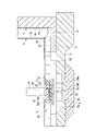
- FIG. 1 It is a sectional side view showing a schematic structure of one embodiment of a ground type cryogenic tank according to the present invention. It is the sectional side view which expanded the basic
- FIG. 1 is a side sectional view showing a schematic configuration of an embodiment of a ground type cryogenic tank according to the present invention, and reference numeral 1 in FIG. 1 denotes a ground type cryogenic tank (hereinafter referred to as a cryogenic tank).
- the low temperature tank 1 is a ground type low temperature tank for storing a low temperature liquefied gas such as LNG, LPG, or liquefied ethylene. In the present embodiment, a low temperature tank for storing LNG is used.
- the low temperature tank 1 is provided on a ground 2 and includes a metal inner tank 3 for storing a low temperature liquefied gas (LNG), and an outer tank 4 surrounding and covering the inner tank 3.
- LNG low temperature liquefied gas
- a tank bottom 6 is formed on the base plate 5, and a cylindrical inner tank 3 is installed on the tank bottom 6.
- the inner tank 3 is formed of a steel plate or the like, has a bottom plate 3 a and a cylindrical side wall 3 b, is disposed on the tank bottom 6, and is installed in the outer tank 4 via the cold insulation layer 7.
- the outer tub 4 includes a side wall portion 4a and a roof portion 4b.
- the side wall portion 4a includes an outer wall 4c made of concrete surrounding the side wall 3b of the inner tub 3, and an outer tub formed of a steel plate attached to the inner peripheral surface thereof.
- the main body 4d is formed.
- the low temperature tank 1 is a double shell tank of a full-containment type.
- the lid 8 is a roof portion of the inner tub 3.
- the lid 8 is formed of, for example, a thin aluminum plate, and simply covers the upper opening of the inner tub 3 without hermetically sealing.
- the lid 8 that covers the inner tank 3 and the roof portion 4b of the outer tank 4 are provided with a pump barrel 9 penetrating them from the inner tank 3 to the outside, and further, A supply pipe (not shown) for supplying low-temperature liquefied gas into the inner tank 3 from the outside is also provided through these.
- a gap is formed between the side wall 3b of the inner tub 3 and the side wall 4a of the outer tub 4, and the cold insulation layer 7 is provided in the gap as described above.
- the cold insulation layer 7 is made of, for example, polyurethane foam (PUF) or granular pearlite.
- a suspended deck 10 is disposed on the lid 8, and a cold insulation layer 11 made of, for example, glass wool is laid on the suspended deck 10.
- the lower side of the bottom plate 3a of the inner tank 3 is constituted by a base plate 5 and a tank bottom 6 formed thereon as shown in the enlarged side sectional view of FIG.
- a base plate hole 5a is formed corresponding to a position where a pump pit described later is formed.
- the base plate hole 5a is formed to a preset depth.
- a reinforcing base plate 5b is provided at a position below the base plate hole 5a.
- the reinforced base plate 5b is formed to be larger than the base plate hole 5a in plan view by a plan view, and the base plate hole 5a is formed to reinforce the thickness of the base plate 5 that is reduced. .
- the tank bottom portion 6 is formed by laminating a pearlite concrete 12 having a cold insulation function and a light-weight concrete 13 for structure in this order in a portion that supports the side wall 3b of the inner tank 3, that is, an annular portion.
- An annular plate 14 is disposed on the lightweight concrete 13, and the side wall 3 b of the inner tub 3 is installed on the annular plate 14.
- a cold insulating material 15 made of foam glass or the like is provided between the annular portion and the outer tub 4. Furthermore, a cold insulating material 16 made of foam glass or the like is provided on the center side of the inner tub 3 from the annular portion. This cold insulating material 16 is laminated in, for example, two layers in order to obtain the set cold insulating performance. Further, the cold insulating material 16 is also provided in the above-described basic plate hole 5a.
- the bottom plate 3a of the inner tank is laid on the cold insulating material 16, and the inner tank 3 is formed by connecting the bottom plate 3a and the annular plate 14 by welding or the like. Furthermore, in this embodiment, the cylindrical hole 17 is formed in the bottom part of the inner tank 3 which consists of such a structure. The hole 17 is formed at a preset depth in the cold insulating material 16 located on the base plate hole 5a to form a pump pit.
- Reference numeral 18 denotes a metal pit body.
- the pit body 18 is formed of a steel plate made of the same material as the bottom plate 3 a of the inner tank 3.
- the pit main body 18 includes a bottomed cylindrical storage portion 18a and a flange portion 18b formed in an upper opening of the storage portion 18a.
- the storage portion 18a is received in the hole portion 17 from above. Yes.
- the height of the accommodating portion 18 a is formed to be sufficiently shallower (lower) than the depth of the hole portion 17, and the outer diameter of the accommodating portion 18 a is sufficiently smaller than the inner diameter of the hole portion 17.
- the flange portion 18 b is formed to have a larger diameter than the inner diameter of the hole portion 17.
- the pit body 18 having such a configuration is accommodated in the hole portion 17 in a state where the accommodating portion 18a is suspended in the hole portion 17 by the flange portion 18b being suspended around the opening portion of the hole portion 17. ing. That is, the accommodating portion 18 a of the pit body 18 is accommodated in the hole portion 17 so that a gap is left between the cold insulating material 16 forming the hole portion 17.
- a cold insulation material is provided to fill the gap. That is, a cold insulation layer (cold insulation material) 19 made of foam glass or polyurethane foam (PUF) is disposed immediately above the cold insulation material 16 in which the hole portion 17 is formed and below the housing portion 18a.
- a cold insulation layer (cold insulation material) 19 made of foam glass or polyurethane foam (PUF) is disposed immediately above the cold insulation material 16 in which the hole portion 17 is formed and below the housing portion 18a.
- a concrete reinforcing body 20 is disposed in contact with the bottom surface D of the steel plate.
- the reinforcing body 20 is a disk-like or square plate-like member having a thickness of about 10 cm to 20 cm, for example, and is formed to be larger than the bottom surface D of the housing portion 18a in a state viewed from above.
- the reinforcing body 20 supports the accommodating portion 18a, and particularly by supporting the outer peripheral edge portion of the bottom surface D of the accommodating portion 18a, a line intensively applied to the corner portion between the bottom plate and the side plate of the accommodating portion 18a. Can receive a load. Accordingly, transmission of the line load concentrated on the corner portion of the accommodating portion 18a to the cold insulation layer 19 is prevented, and as a result, the cold load is caused by the linear load in the cold insulation layer 19 and the cold insulation material 16 located therebelow. Generation of stress is prevented.
- RC concrete reinforced concrete reinforced with reinforcing bars is preferably used so that the linear loads are not transmitted to the cold insulation layer 19 under the linear loads.
- the relatively thin thickness for example, about 10 cm to 20 cm
- the thickness of the reinforcing body 20 is limited to a thin thickness of about 10 cm to 20 cm, for example, and the cold insulation layer 19 is formed thereunder.
- the provision of the cold insulation layer 19 compensates for a decrease in heat insulation (cold insulation) due to the arrangement of the reinforcing body 20.
- thermal insulation concrete or the like can be used as the reinforcing body 20 in order to suppress a decrease in thermal insulation (cold insulation).
- a cold insulation layer 21 made of foam glass or polyurethane foam (PUF) is disposed on the inner peripheral surface of the cold insulation material 16 in which the hole portion 17 is formed and on the side of the housing portion 18a.
- the cold insulation layer 21 can be disposed in the same process as the cold insulation layer 19.
- the glass wool 22 as a cold insulating material is arrange
- the glass wool 22 absorbs the displacement of the pit body 18 due to the thermal contraction of the bottom plate 3a of the inner tub 3, and always fills the space between the side peripheral surface of the pit body 18 and the cold insulation material 16 without any gaps, and exhibits a good cold insulation function. can do.
- the flange portion 18b of the pit main body 18 is suspended around the peripheral portion of the opening of the hole portion 17, and in this state, is welded to the bottom plate 3a of the inner tank 3 and is liquid-tightly connected.
- the pit body 18 also substantially constitutes the bottom surface of the inner tank 3.
- a pump pit 23 is formed by a recess (hole) formed by the accommodating portion 18 a of the pit body 18.
- a pump 24 is disposed at the lower end of the pump barrel 9.
- This pump 24 is provided with a lid portion 24b that opens and closes by operating the drive portion 24a to form a liquid suction port, and opens the lid portion 24b and sucks in liquid as indicated by an arrow, thereby allowing the inside of the pump barrel 9 to pass through. It is configured to dispense liquid through the tank.
- a concrete reinforcing body 20 that supports the bottom surface D is provided on the bottom surface D side of the pit main body 18, and a cold insulation layer 19 (cold insulation material) is provided below the reinforcement body 20. Therefore, in particular, the linear load applied to the corner (outer peripheral edge) of the bottom of the pit body 18 can be received by the reinforcing body 20, and therefore the transmission of the linear load to the cold insulation layer 19 provided therebelow. Can be prevented. Thereby, generation
- the glass wool 22 is arranged in a compressed state outside the side peripheral surface of the pit main body 18 in the hole portion 17, when the low-temperature liquefied gas is put into the inner tank 3, the thermal contraction of the bottom plate 3 a is performed. Even if the pit main body 18 is displaced by this, the glass wool 22 absorbs this displacement, and always fills the gap between the side peripheral surface of the pit main body 18 and the cold insulation material 16 without any gap, so that the cold insulation function is exhibited well. Therefore, it is possible to prevent the cooling performance of the low temperature tank 1 from being lowered due to the formation of the pump pit 23.
- the present invention is not limited to the above-described embodiment, and various modifications can be made without departing from the gist of the present invention.
- a disk-shaped or square-plate-shaped member is used as the reinforcing body 20, but the reinforcing body 20 in the present invention only needs to support at least the outer peripheral edge portion of the bottom surface D of the pit body 18.
- the reinforcement body receives a linear load intensively applied to the corner portion (outer peripheral edge portion) of the bottom of the pit main body 18 and suppresses a decrease in cold insulation performance due to the arrangement of the reinforcement body without heat insulation.
- the cold insulation performance of the low temperature tank 1 can be enhanced.
Landscapes
- Engineering & Computer Science (AREA)
- Physics & Mathematics (AREA)
- Thermal Sciences (AREA)
- Mechanical Engineering (AREA)
- General Engineering & Computer Science (AREA)
- Filling Or Discharging Of Gas Storage Vessels (AREA)
Abstract
低温液化ガスを貯留する金属製の内槽(3)と、内槽(3)を囲うコンクリート製の外壁(4c)を有する外槽(4)と、を備える地上式の低温タンクである。内槽(3)の底部には、内槽(3)の底面から予め設定された深さを有する穴部(17)が形成され、有底筒状の収容部(18a)を有する金属製のピット本体(18)が、収容部(18a)が穴部(17)内に収容された状態で設けられている。穴部(17)内には、ピット本体(18)の底面(D)側に、少なくともピット本体(18)の底面(D)の外周縁部を支持する補強体(20)が設けられている。また、補強体(20)の下側には保冷材(19)が設けられている。
Description
本発明は、地上式低温タンクに関する。
本願は、2013年8月23日に日本に出願された日本国特願2013-173598号に基づき優先権を主張し、その内容をここに援用する。
本願は、2013年8月23日に日本に出願された日本国特願2013-173598号に基づき優先権を主張し、その内容をここに援用する。
従来、例えばLNG(Liquefied Natural Gas)等の低温の液化ガスを貯留する低温タンクとして、低温液化ガスを貯留する金属製の内槽と、この内槽を囲うコンクリート製の外壁を有した外槽と、を備えるfull containment形式の二重殻タンクが用いられている。このような低温タンクでは、貯留した液化ガスを外部に払い出すために、液払出用のポンプをタンク内のポンプバレル内に設置している。
液払出用のポンプは、前記の二重殻タンクでは屋根を貫通するバレルの下端に収納され、バレルの下端から液化ガスを吸い込むように構成されている。
このポンプでは、例えば液面が吸込口より1~3mほどの高さにないと、渦や泡を吸い込むことによって液の払い出しが不能となる。
したがって、この高さに底面から吸込口までの高さを加えた高さに相当する分の液が、タンクから払い出すことができなくなり、その結果、タンクの有効貯留量が大きく減少する。
このポンプでは、例えば液面が吸込口より1~3mほどの高さにないと、渦や泡を吸い込むことによって液の払い出しが不能となる。
したがって、この高さに底面から吸込口までの高さを加えた高さに相当する分の液が、タンクから払い出すことができなくなり、その結果、タンクの有効貯留量が大きく減少する。
これに対処するため、例えばタンク用のポンプピットを形成することが考えられる。タンク用のポンプピットは、地下式でメンブレン式の低温タンクにおいて提案されている(例えば、特許文献1、特許文献2、特許文献3参照)。
ところで、地下式のタンクでは地上に突出する部分が少ないため、タンクの高さ(深さ)の制約が少ない。そのため、タンクを埋設する穴の深さを十分に深くすることにより、基礎版と内槽との間に配設する保冷層も十分な厚さに施工することができる。これに対して地上式のタンクでは、景観上の理由などからタンクの高さに制約がある。そのためタンクの有効貯留量を十分に確保しようとすると、その分、基礎版と内槽との間に配設する保冷層の厚さが制限されてしまう。
上記のように、地上式のタンクでは特に基礎版と内槽との間に配設する保冷層の厚さが制限される。そのため、タンク用のポンプピットを設けるのが難しい。
すなわち、地上式のタンクにポンプピットを設けようとした場合、タンクの底面に穴部を形成し、この穴部内に金属製で有底筒状のピット本体を設けることが想定される。しかしながら、ピット本体では特に底部のコーナー部において線荷重が集中的にかかり易く、したがって、タンクの底面のうち、ピット本体の底部を受ける部位では線荷重が伝わることで大きなストレスを生じる。すると、保冷層は泡ガラスなどによって形成されているため、このストレスによって保冷層に割れなどが起こり、保冷性能が低下してしまう。
すなわち、地上式のタンクにポンプピットを設けようとした場合、タンクの底面に穴部を形成し、この穴部内に金属製で有底筒状のピット本体を設けることが想定される。しかしながら、ピット本体では特に底部のコーナー部において線荷重が集中的にかかり易く、したがって、タンクの底面のうち、ピット本体の底部を受ける部位では線荷重が伝わることで大きなストレスを生じる。すると、保冷層は泡ガラスなどによって形成されているため、このストレスによって保冷層に割れなどが起こり、保冷性能が低下してしまう。
地下式のタンクであれば、前述したように基礎版と内槽との間に配設する保冷層を十分な厚さに施工することができる。したがって前記の線荷重に起因するストレスによる保冷性能の低下はほとんど問題にならない。しかし、地上式のタンクでは保冷層の厚さが制限されているため、前記のストレスによる保冷性能の低下は低温タンク自体の性能を大きく損なう。
本発明は前記事情に鑑みてなされたもので、その目的とするところは、保冷性能の低下を防止しつつポンプピットを設けることが可能な、地上式低温タンクの提供にある。
本発明の地上式低温タンクは、低温液化ガスを貯留する金属製の内槽と、この内槽を囲うコンクリート製の外壁を有する外槽と、を備える。また、内槽の底部には、内槽の底面から予め設定された深さを有する穴部が形成され、有底筒状の収容部を有する金属製のピット本体が、収容部が穴部内に収容された状態で設けられ、穴部内には、ピット本体の底面側に、少なくともピット本体の底面の外周縁部を支持する補強体が設けられ、補強体の下側に保冷材が設けられている。また、補強体は例えばコンクリート製とする。
また、この地上式低温タンクにおいて、穴部内には、ピット本体の側周面の外側に、グラスウールが圧縮した状態で配置されていることが好ましい。
また、この地上式低温タンクにおいて、補強体が、ピット本体の底面の外周縁部を支持するように環状に形成され、環状の補強体の内側に、保冷材が設けられていてもよい。
本発明の地上式低温タンクは、ピット本体の底面側に、少なくともピット本体の底面の外周縁部を支持するコンクリート製の補強体を設け、補強体の下側に保冷材を設けている。そのため、特にピット本体の底部のコーナー部(外周縁部)に集中的にかかる線荷重を補強体で受けることができ、したがってその下側に設けられた保冷材への線荷重の伝達を防止することができる。これにより、線荷重が伝わることに起因するストレスによる、保冷層における割れなどの発生と、それに起因する保冷性能の低下を防止することができる。すなわち、保冷性能の低下を防止しつつポンプピットを設けることができる。
以下、図面を参照して本発明の地上式低温タンクを詳しく説明する。なお、以下の図面においては、各部材を認識可能な大きさとするため、各部材の縮尺を適宜変更している。
図1は、本発明に係る地上式低温タンクの一実施形態の概略構成を示す側断面図であり、図1中符号1は地上式低温タンク(以下、低温タンクと記す。)である。この低温タンク1は、LNGやLPG、液化エチレンなどの低温液化ガスを貯留する地上式低温タンクである。なお、本実施形態では、LNGを貯留する低温タンクとする。
図1は、本発明に係る地上式低温タンクの一実施形態の概略構成を示す側断面図であり、図1中符号1は地上式低温タンク(以下、低温タンクと記す。)である。この低温タンク1は、LNGやLPG、液化エチレンなどの低温液化ガスを貯留する地上式低温タンクである。なお、本実施形態では、LNGを貯留する低温タンクとする。
この低温タンク1は、グランド2上に設けられ、低温液化ガス(LNG)を貯留する金属製の内槽3と、この内槽3の周囲を囲ってこれを覆う外槽4と、を備えて構成された二重殻構造を有する。すなわち、グランド2上にコンクリート製の基礎版(基礎)5が据え付けられ、基礎版5上に、円筒状の外槽(槽)4が設置されている。また、基礎版5上には槽底部6が形成され、この槽底部6上に円筒状の内槽3が設置されている。
内槽3は、鋼板等によって形成され、底板3aと円筒状の側壁3bとを有し、槽底部6上に配置され、かつ、保冷層7を介して外槽4内に設置されている。外槽4は、側壁部4aと屋根部4bとからなり、側壁部4aは、内槽3の側壁3bを囲うコンクリート製の外壁4cと、その内周面に貼設された鋼板からなる外槽本体4dとによって形成されている。このような構成によって低温タンク1は、full containment形式の二重殻タンクとなっている。
また、内槽3の上部開口は、蓋体8で覆われ、したがってこの蓋体8は、内槽3の屋根部となっている。ただし、この蓋体8は、例えば薄いアルミニウム板によって形成されており、内槽3の上部開口を気密に封止することなく、単に覆っている。内槽3を覆う蓋体8、および外槽4の屋根部4bには、内槽3内から外部に低温液化ガスを払い出すためのポンプバレル9が、これらを貫通して設けられ、さらに、外部から内槽3内に低温液化ガスを供給するための供給管(図示せず)も、これらを貫通して設けられている。
内槽3の側壁3bと外槽4の側壁部4aとの間には隙間が形成され、この隙間には前述したように保冷層7が設けられている。この保冷層7は、例えばポリウレタンフォーム(PUF)や粒状のパーライトなどによって形成されている。
蓋体8の上にはサスペンデッドデッキ10が配置されており、このサスペンデッドデッキ10上には例えばグラスウールからなる保冷層11が敷設されている。
蓋体8の上にはサスペンデッドデッキ10が配置されており、このサスペンデッドデッキ10上には例えばグラスウールからなる保冷層11が敷設されている。
内槽3の底板3aの下側は、図2の拡大側断面図に示すように、基礎版5およびその上に形成された槽底部6によって構成されている。基礎版5には、後述するポンプピットを形成する位置に対応して、基礎版穴部5aが形成されている。基礎版穴部5aは、予め設定された深さに形成されている。また、基礎版穴部5aの下方となる位置には、補強基礎版5bが設けられている。補強基礎版5bは、平面視して、基礎版穴部5aより一回り以上大きく形成され、基礎版穴部5aを形成したことで基礎版5の厚さが薄くなった分を補強している。
槽底部6は、内槽3の側壁3bを支持する部位、すなわちアニュラー部では、保冷機能を有するパーライトコンクリート12と、構造用の軽量コンクリート13とがこの順に積層されて形成されている。そして、軽量コンクリート13上にアニュラープレート14が配置され、このアニュラープレート14上に内槽3の側壁3bが設置されている。
また、このアニュラー部と外槽4との間には、泡ガラス等からなる保冷材15が設けられている。
さらに、アニュラー部より内槽3の中央側にも、泡ガラス等からなる保冷材16が設けられている。この保冷材16は、設定された保冷性能を得るべく、例えば二層に積層されている。また、この保冷材16は、前記した基礎版穴部5a内にも設けられている。
さらに、アニュラー部より内槽3の中央側にも、泡ガラス等からなる保冷材16が設けられている。この保冷材16は、設定された保冷性能を得るべく、例えば二層に積層されている。また、この保冷材16は、前記した基礎版穴部5a内にも設けられている。
そして、このような保冷材16上に内槽の底板3aが敷設され、底板3aと前記アニュラープレート14とが溶接等によって接続されることにより、内槽3が形成されている。さらに、本実施形態では、このような構成からなる内槽3の底部に、円筒状の穴部17が形成されている。穴部17は、ポンプピットを形成するため、前記した基礎版穴部5a上に位置する保冷材16に、予め設定された深さに形成されている。
符号18は金属製のピット本体である。具体的には、ピット本体18は、内槽3の底板3aと同じ材質の鋼板によって形成される。
ピット本体18は、有底円筒状の収容部18aと、この収容部18aの上部開口部に形成されたフランジ部18bとから構成され、収容部18aが、上方から穴部17内に収容されている。収容部18aの高さは穴部17の深さより十分に浅く(低く)なるように形成され、また、収容部18aの外径は穴部17の内径より十分に小さく形成されている。さらに、フランジ部18bは、穴部17の内径より大径に形成されている。
ピット本体18は、有底円筒状の収容部18aと、この収容部18aの上部開口部に形成されたフランジ部18bとから構成され、収容部18aが、上方から穴部17内に収容されている。収容部18aの高さは穴部17の深さより十分に浅く(低く)なるように形成され、また、収容部18aの外径は穴部17の内径より十分に小さく形成されている。さらに、フランジ部18bは、穴部17の内径より大径に形成されている。
このような構成のピット本体18は、フランジ部18bが穴部17の開口の周辺部に懸架されることにより、収容部18aが穴部17内に吊された状態で、穴部17に収容されている。すなわち、ピット本体18の収容部18aは、穴部17を形成する保冷材16との間に隙間が空くよう、穴部17に収容されている。
このような収容部18aと保冷材16との間の隙間には、この隙間を埋めるべく、保冷材が設けられている。すなわち、穴部17を形成した保冷材16の直上で、かつ、収容部18aの下方に、泡ガラスやポリウレタンフォーム(PUF)からなる保冷層(保冷材)19が配設されている。
そして、この保冷層19とピット本体18の底面D(より正確には収容部18aの底面D)との間には、すなわち穴部17における、収容部18aの底面D側には、収容部18aの底面Dに接してコンクリート製の補強体20が配設されている。この補強体20は、例えば厚さが10cm~20cm程度に形成された円板状または正方形板状の部材で、平面視した状態で収容部18aの底面Dより一回り以上大きく形成されている。
これにより、補強体20は収容部18aを支持し、特に収容部18aの底面Dの外周縁部を支持することにより、収容部18aの底板と側板との間のコーナー部に集中的にかかる線荷重を受けることができる。したがって、収容部18aのコーナー部に集中的にかかった線荷重の保冷層19への伝達が防止され、その結果、保冷層19やその下に位置する保冷材16における、前記線荷重に起因するストレスの発生が防止されている。
ここで、補強体20としては、前記線荷重を受けてこの線荷重がその下の保冷層19に伝わらないように、鉄筋で補強したRCコンクリート(鉄筋コンクリート)が好適に用いられる。このような高強度のRCコンクリートを用いることにより、比較的薄い厚さ(例えば10cm~20cm程度)でも前記線荷重に十分に耐え得る。なお、このようなRCコンクリートには断熱性能がほとんどなく、したがって保冷材としての機能は望めない。よって、この補強体20の厚さが例えば10cm~20cm程度の薄い厚さに制限され、その下に保冷層19を形成している。すなわち、保冷層19を配設することで、補強体20を配置することによる断熱性(保冷性)の低下を補っている。ただし、設計上保冷層19の厚さを十分にとれない場合などでは、断熱性(保冷性)の低下を抑えるべく、補強体20として断熱性コンクリートなどを用いることもできる。
また、穴部17を形成した保冷材16の内周面上で、かつ、収容部18aの側方には、泡ガラスやポリウレタンフォーム(PUF)からなる保冷層21が配設されている。この保冷層21は、保冷層19と同一の工程で配設することができる。そして、この保冷層21と収容部18aの側周面との間、すなわちピット本体18の側周面の外側には、保冷材としてのグラスウール22が圧縮された状態で配置されている。このグラスウール22により、内槽3の底板3aの熱収縮によるピット本体18の変位を吸収し、ピット本体18の側周面と保冷材16との間を常に隙間無く埋めて保冷機能を良好に発揮することができる。
ピット本体18のフランジ部18bは、前記したように穴部17の開口の周辺部に懸架され、その状態で内槽3の底板3aに溶接されて液密に接続されている。これにより、ピット本体18も実質的に内槽3の底面を構成する。そして、ピット本体18の収容部18aによって形成される凹部(穴部)により、ポンプピット23が形成されている。
ポンプピット23には、ポンプバレル9の下端部が差し込まれている。そして、このポンプバレル9の下端部には、ポンプ24が配置されている。このポンプ24は、駆動部24aを動作させることにより開閉して液吸引口を形成する蓋部24bを備え、蓋部24bを開けて矢印で示すように液体を吸い込むことにより、ポンプバレル9内を通って液体をタンク外に払い出すよう構成されている。
この低温タンク1では、ピット本体18の底面D側に底面Dを支持するコンクリート製の補強体20を設け、この補強体20の下側に保冷層19(保冷材)を設けている。そのため、特にピット本体18の底部のコーナー部(外周縁部)に集中的にかかる線荷重を補強体20で受けることができ、したがってその下側に設けられた保冷層19への線荷重の伝達を防止することができる。これにより、線荷重が伝わることに起因するストレスによよる、保冷層19における割れなどの発生と、それに起因する保冷性能の低下を防止することができる。すなわち、この低温タンク1にあっては、保冷性能の低下を防止しつつポンプピット23を設け、タンクの有効貯留量を十分に確保することができる。
また、穴部17内において、ピット本体18の側周面の外側にグラスウール22を圧縮した状態で配置しているので、内槽3内に低温液化ガスを入れた際などに底板3aの熱収縮によってピット本体18が変位しても、グラスウール22がこの変位を吸収し、ピット本体18の側周面と保冷材16との間を常に隙間無く埋めて保冷機能を良好に発揮する。
したがって、ポンプピット23の形成に伴う低温タンク1の保冷性能の低下を防止することができる。
したがって、ポンプピット23の形成に伴う低温タンク1の保冷性能の低下を防止することができる。
なお、本発明は前記実施形態に限定されることなく、本発明の主旨を逸脱しない範囲で種々の変更が可能である。
例えば、前記実施形態では補強体20として円板状または正方形板状の部材を用いたが、本発明における補強体20としては、少なくともピット本体18の底面Dの外周縁部を支持できればよく、したがって、例えばピット本体18の底面Dの外周縁部を支持するように円環状などに形成されていてもよい。その場合に、円環状の補強体の内側(内部孔内)には、保冷材を設けることが望ましい。このように構成することにより、補強体によってピット本体18の底部のコーナー部(外周縁部)に集中的にかかる線荷重を受けるとともに、断熱性のない補強体の配置による保冷性能の低下を抑制し、低温タンク1の保冷性能を高めることができる。
例えば、前記実施形態では補強体20として円板状または正方形板状の部材を用いたが、本発明における補強体20としては、少なくともピット本体18の底面Dの外周縁部を支持できればよく、したがって、例えばピット本体18の底面Dの外周縁部を支持するように円環状などに形成されていてもよい。その場合に、円環状の補強体の内側(内部孔内)には、保冷材を設けることが望ましい。このように構成することにより、補強体によってピット本体18の底部のコーナー部(外周縁部)に集中的にかかる線荷重を受けるとともに、断熱性のない補強体の配置による保冷性能の低下を抑制し、低温タンク1の保冷性能を高めることができる。
保冷性能の低下を防止しつつポンプピットを設けることが可能な地上式低温タンクを提供することができる。
1 低温タンク、
3 内槽、
4 外槽、
4c 外壁、
5 基礎版、
6 槽底部、
9 ポンプバレル、
17 穴部、
18 ピット本体、
18a 収容部、
19 保冷層(保冷材)、
20 補強体、
22 グラスウール、
23 ポンプピット、
D ピット本体の底面
3 内槽、
4 外槽、
4c 外壁、
5 基礎版、
6 槽底部、
9 ポンプバレル、
17 穴部、
18 ピット本体、
18a 収容部、
19 保冷層(保冷材)、
20 補強体、
22 グラスウール、
23 ポンプピット、
D ピット本体の底面
Claims (5)
- 低温液化ガスを貯留する金属製の内槽と、この内槽を囲うコンクリート製の外壁を有する外槽と、を備える地上式の低温タンクにおいて、
前記内槽の底部には、前記内槽の底面から予め設定された深さを有する穴部が形成され、有底筒状の収容部を有する金属製のピット本体が、収容部が前記穴部内に収容された状態で設けられ、
前記穴部内には、前記ピット本体の底面側に、少なくとも前記ピット本体の底面の外周縁部を支持する補強体が設けられ、
前記補強体の下側に保冷材が設けられている地上式低温タンク。 - 前記穴部内には、前記ピット本体の側周面の外側に、グラスウールが圧縮した状態で配置されている請求項1記載の地上式低温タンク。
- 前記補強体が、前記ピット本体の底面の外周縁部を支持するように環状に形成されており、環状の補強体の内側に、保冷材が設けられている請求項1に記載の地上式低温タンク。
- 前記補強体が、前記ピット本体の底面の外周縁部を支持するように環状に形成されており、環状の補強体の内側に、保冷材が設けられている請求項2に記載の地上式低温タンク。
- 前記補強体がコンクリート製である請求項1~4のいずれか1項に記載の地上式低温タンク。
Priority Applications (1)
| Application Number | Priority Date | Filing Date | Title |
|---|---|---|---|
| US15/007,453 US9945515B2 (en) | 2013-08-23 | 2016-01-27 | Above-ground low-temperature tank |
Applications Claiming Priority (2)
| Application Number | Priority Date | Filing Date | Title |
|---|---|---|---|
| JP2013173598A JP6036605B2 (ja) | 2013-08-23 | 2013-08-23 | 地上式低温タンク |
| JP2013-173598 | 2013-08-23 |
Related Child Applications (1)
| Application Number | Title | Priority Date | Filing Date |
|---|---|---|---|
| US15/007,453 Continuation US9945515B2 (en) | 2013-08-23 | 2016-01-27 | Above-ground low-temperature tank |
Publications (1)
| Publication Number | Publication Date |
|---|---|
| WO2015025952A1 true WO2015025952A1 (ja) | 2015-02-26 |
Family
ID=52483723
Family Applications (1)
| Application Number | Title | Priority Date | Filing Date |
|---|---|---|---|
| PCT/JP2014/071991 Ceased WO2015025952A1 (ja) | 2013-08-23 | 2014-08-22 | 地上式低温タンク |
Country Status (3)
| Country | Link |
|---|---|
| US (1) | US9945515B2 (ja) |
| JP (1) | JP6036605B2 (ja) |
| WO (1) | WO2015025952A1 (ja) |
Cited By (1)
| Publication number | Priority date | Publication date | Assignee | Title |
|---|---|---|---|---|
| JP2018035902A (ja) * | 2016-09-01 | 2018-03-08 | 鹿島建設株式会社 | 低温液化ガス地下タンク |
Families Citing this family (5)
| Publication number | Priority date | Publication date | Assignee | Title |
|---|---|---|---|---|
| CA2853324C (en) * | 2014-06-03 | 2016-02-23 | Westport Power Inc. | Cryogenic storage vessel |
| EP3336410B1 (en) * | 2016-12-15 | 2021-12-01 | Gas and Heat S.p.A. | Cryogenic plant |
| KR20220062653A (ko) * | 2019-09-24 | 2022-05-17 | 엑손모빌 업스트림 리서치 캄파니 | 선박의 이중 목적 극저온 탱크 또는 lng 및 액화 질소용 부유식 저장 유닛용 화물 스트리핑 기능 |
| CN114413161A (zh) * | 2022-01-26 | 2022-04-29 | 中海石油气电集团有限责任公司 | 带有泵井槽保冷系统的lng全容储罐 |
| FR3140926B1 (fr) * | 2022-10-14 | 2024-09-06 | Gaztransport Et Technigaz | Cuve de stockage de gaz liquide comprenant un puisard |
Citations (5)
| Publication number | Priority date | Publication date | Assignee | Title |
|---|---|---|---|---|
| JPS5742299U (ja) * | 1980-08-22 | 1982-03-08 | ||
| JPH07285593A (ja) * | 1994-04-13 | 1995-10-31 | Ishikawajima Harima Heavy Ind Co Ltd | 地下タンク |
| JP2000346294A (ja) * | 1999-06-04 | 2000-12-15 | Ishikawajima Harima Heavy Ind Co Ltd | 平底円筒型低温タンクの耐震構造 |
| JP2001108198A (ja) * | 1999-10-04 | 2001-04-20 | Kawasaki Heavy Ind Ltd | Lngなどの低温地下式貯槽 |
| JP2014194256A (ja) * | 2013-03-29 | 2014-10-09 | Ihi Corp | 低温液体タンク |
Family Cites Families (7)
| Publication number | Priority date | Publication date | Assignee | Title |
|---|---|---|---|---|
| DE2936421C2 (de) * | 1979-09-08 | 1982-10-28 | Dyckerhoff & Widmann AG, 8000 München | Doppelwandiger Behälter für tiefkalte Flüssigkeiten,z.B. Flüssiggas |
| JP3978892B2 (ja) | 1998-09-28 | 2007-09-19 | 株式会社Ihi | タンク用ポンプピットおよびその施工方法 |
| JP4014743B2 (ja) | 1998-12-04 | 2007-11-28 | 東京ガス・エンジニアリング株式会社 | タンク用ポンプピット |
| JP2003278998A (ja) | 2002-03-27 | 2003-10-02 | Jfe Engineering Kk | 低温貯槽のポンプピット構造 |
| WO2011093227A1 (ja) * | 2010-01-28 | 2011-08-04 | 大阪瓦斯株式会社 | 低温タンク |
| CN102792084B (zh) * | 2010-03-17 | 2014-11-26 | 气体产品与化学公司 | 低温存储罐 |
| JP2014224553A (ja) | 2013-05-15 | 2014-12-04 | 株式会社Ihi | 低温液化ガスタンク |
-
2013
- 2013-08-23 JP JP2013173598A patent/JP6036605B2/ja not_active Expired - Fee Related
-
2014
- 2014-08-22 WO PCT/JP2014/071991 patent/WO2015025952A1/ja not_active Ceased
-
2016
- 2016-01-27 US US15/007,453 patent/US9945515B2/en not_active Expired - Fee Related
Patent Citations (5)
| Publication number | Priority date | Publication date | Assignee | Title |
|---|---|---|---|---|
| JPS5742299U (ja) * | 1980-08-22 | 1982-03-08 | ||
| JPH07285593A (ja) * | 1994-04-13 | 1995-10-31 | Ishikawajima Harima Heavy Ind Co Ltd | 地下タンク |
| JP2000346294A (ja) * | 1999-06-04 | 2000-12-15 | Ishikawajima Harima Heavy Ind Co Ltd | 平底円筒型低温タンクの耐震構造 |
| JP2001108198A (ja) * | 1999-10-04 | 2001-04-20 | Kawasaki Heavy Ind Ltd | Lngなどの低温地下式貯槽 |
| JP2014194256A (ja) * | 2013-03-29 | 2014-10-09 | Ihi Corp | 低温液体タンク |
Cited By (1)
| Publication number | Priority date | Publication date | Assignee | Title |
|---|---|---|---|---|
| JP2018035902A (ja) * | 2016-09-01 | 2018-03-08 | 鹿島建設株式会社 | 低温液化ガス地下タンク |
Also Published As
| Publication number | Publication date |
|---|---|
| US9945515B2 (en) | 2018-04-17 |
| JP2015040619A (ja) | 2015-03-02 |
| JP6036605B2 (ja) | 2016-11-30 |
| US20160138758A1 (en) | 2016-05-19 |
Similar Documents
| Publication | Publication Date | Title |
|---|---|---|
| JP6036605B2 (ja) | 地上式低温タンク | |
| JP5033169B2 (ja) | 陸上用液化ガス貯蔵タンクの二重防壁及びその建設方法 | |
| US10533707B2 (en) | Ground liquefied natural gas storage tank and method for manufacturing the same | |
| JP5757332B2 (ja) | 低温タンクの建設方法 | |
| RU2016150943A (ru) | Герметичный и изолированный резервуар, расположенный в плавучем двойном корпусе | |
| KR20120138756A (ko) | 저온 탱크 | |
| KR20120004652A (ko) | 극저온 액체저장탱크의 단열 패널 및 이를 갖는 단열 구조체 | |
| JP6484151B2 (ja) | 地下構造物、地下構造物の構築方法 | |
| KR100990179B1 (ko) | 액화천연가스 운반선 화물창의 단열구조 | |
| KR20200118201A (ko) | 액화 가스 탱크 | |
| KR100981416B1 (ko) | 앵커 구조체 및 이를 갖는 액화천연가스 저장탱크 | |
| KR102348463B1 (ko) | 액화가스 화물창 및 그 액화가스 화물창을 구비하는 운반선 | |
| JP6155758B2 (ja) | 低温液体タンク | |
| KR20120131302A (ko) | 액화가스 저장탱크 및 이를 포함하는 선박 | |
| KR102595970B1 (ko) | Lng탱크의 펌프타워 지붕용 결합 장치 | |
| KR101390308B1 (ko) | 화물창 및 그 제조방법 | |
| CN103370567A (zh) | Lng储存罐 | |
| KR102543441B1 (ko) | 펌프타워 베이스 서포트 역할을 겸하는 비상배출장치를 포함하는 액화천연가스 저장탱크 | |
| KR20110138870A (ko) | 슬로싱 저감 수단을 가진 부유식 구조물의 lng 저장탱크 | |
| KR101177819B1 (ko) | 액화천연가스 화물창의 화물 양하역 장치와 이를 포함하는 액화천연가스 운반선 및 부유식 해상구조물 | |
| JP2024503477A (ja) | 液化ガス貯蔵タンク及びそれを含む船舶 | |
| KR20120057529A (ko) | 육상용 액화가스 저장탱크 | |
| WO2024241781A1 (ja) | 地上式貯蔵タンク | |
| JP2019031820A (ja) | 地下タンク及び地下タンクの施工方法 | |
| KR102785264B1 (ko) | 액화가스 저장탱크의 단열박스 보강구조 |
Legal Events
| Date | Code | Title | Description |
|---|---|---|---|
| 121 | Ep: the epo has been informed by wipo that ep was designated in this application |
Ref document number: 14838720 Country of ref document: EP Kind code of ref document: A1 |
|
| NENP | Non-entry into the national phase |
Ref country code: DE |
|
| 122 | Ep: pct application non-entry in european phase |
Ref document number: 14838720 Country of ref document: EP Kind code of ref document: A1 |