WO2015025707A1 - 照明制御システム、端末およびその照明制御方法 - Google Patents
照明制御システム、端末およびその照明制御方法 Download PDFInfo
- Publication number
- WO2015025707A1 WO2015025707A1 PCT/JP2014/070563 JP2014070563W WO2015025707A1 WO 2015025707 A1 WO2015025707 A1 WO 2015025707A1 JP 2014070563 W JP2014070563 W JP 2014070563W WO 2015025707 A1 WO2015025707 A1 WO 2015025707A1
- Authority
- WO
- WIPO (PCT)
- Prior art keywords
- control
- state
- lighting
- terminal
- unit
- Prior art date
Links
Images


Classifications
-
- H—ELECTRICITY
- H04—ELECTRIC COMMUNICATION TECHNIQUE
- H04L—TRANSMISSION OF DIGITAL INFORMATION, e.g. TELEGRAPHIC COMMUNICATION
- H04L12/00—Data switching networks
- H04L12/28—Data switching networks characterised by path configuration, e.g. LAN [Local Area Networks] or WAN [Wide Area Networks]
- H04L12/2803—Home automation networks
- H04L12/2816—Controlling appliance services of a home automation network by calling their functionalities
- H04L12/282—Controlling appliance services of a home automation network by calling their functionalities based on user interaction within the home
-
- H—ELECTRICITY
- H05—ELECTRIC TECHNIQUES NOT OTHERWISE PROVIDED FOR
- H05B—ELECTRIC HEATING; ELECTRIC LIGHT SOURCES NOT OTHERWISE PROVIDED FOR; CIRCUIT ARRANGEMENTS FOR ELECTRIC LIGHT SOURCES, IN GENERAL
- H05B47/00—Circuit arrangements for operating light sources in general, i.e. where the type of light source is not relevant
- H05B47/10—Controlling the light source
- H05B47/175—Controlling the light source by remote control
- H05B47/19—Controlling the light source by remote control via wireless transmission
-
- H—ELECTRICITY
- H05—ELECTRIC TECHNIQUES NOT OTHERWISE PROVIDED FOR
- H05B—ELECTRIC HEATING; ELECTRIC LIGHT SOURCES NOT OTHERWISE PROVIDED FOR; CIRCUIT ARRANGEMENTS FOR ELECTRIC LIGHT SOURCES, IN GENERAL
- H05B47/00—Circuit arrangements for operating light sources in general, i.e. where the type of light source is not relevant
- H05B47/10—Controlling the light source
- H05B47/175—Controlling the light source by remote control
- H05B47/196—Controlling the light source by remote control characterised by user interface arrangements
- H05B47/1965—Controlling the light source by remote control characterised by user interface arrangements using handheld communication devices
-
- H—ELECTRICITY
- H05—ELECTRIC TECHNIQUES NOT OTHERWISE PROVIDED FOR
- H05B—ELECTRIC HEATING; ELECTRIC LIGHT SOURCES NOT OTHERWISE PROVIDED FOR; CIRCUIT ARRANGEMENTS FOR ELECTRIC LIGHT SOURCES, IN GENERAL
- H05B47/00—Circuit arrangements for operating light sources in general, i.e. where the type of light source is not relevant
- H05B47/10—Controlling the light source
- H05B47/175—Controlling the light source by remote control
- H05B47/198—Grouping of control procedures or address assignation to light sources
-
- H—ELECTRICITY
- H04—ELECTRIC COMMUNICATION TECHNIQUE
- H04L—TRANSMISSION OF DIGITAL INFORMATION, e.g. TELEGRAPHIC COMMUNICATION
- H04L12/00—Data switching networks
- H04L12/28—Data switching networks characterised by path configuration, e.g. LAN [Local Area Networks] or WAN [Wide Area Networks]
- H04L12/2803—Home automation networks
- H04L2012/284—Home automation networks characterised by the type of medium used
- H04L2012/2841—Wireless
-
- H—ELECTRICITY
- H04—ELECTRIC COMMUNICATION TECHNIQUE
- H04L—TRANSMISSION OF DIGITAL INFORMATION, e.g. TELEGRAPHIC COMMUNICATION
- H04L12/00—Data switching networks
- H04L12/28—Data switching networks characterised by path configuration, e.g. LAN [Local Area Networks] or WAN [Wide Area Networks]
- H04L12/2803—Home automation networks
- H04L2012/2847—Home automation networks characterised by the type of home appliance used
- H04L2012/285—Generic home appliances, e.g. refrigerators
Definitions
- the present invention relates to an illumination control system, and more particularly, to an illumination control system that performs state control for a plurality of illuminations, a terminal, an illumination control method thereof, and a program that causes a computer to execute the method.
- a lighting control system has been proposed in which a plurality of lighting devices are divided into groups and turned on or off in groups in a relatively large space such as an office.
- a system has been proposed in which a group is set for a plurality of lighting devices, and lighting is performed with a dimming rate different for each group, so that the group to which the plurality of lighting devices belong can be visually confirmed.
- a dimming rate different for each group
- This invention is made
- the present invention has been made to solve the above-described problems, and a first aspect of the present invention is an illumination control system including a plurality of illumination devices and a terminal that performs wireless communication with the plurality of illumination devices.
- Each of the plurality of lighting devices detects a state holding unit that holds a state of the own device, an illumination identifier holding unit that holds an identifier of the own device, and a control instruction for the own device, and detects the state.
- a control instruction detection unit that updates the state held by the holding unit to a state according to the control instruction, a light emitting unit that emits light according to the state held by the state holding unit, and the detection detected by the control instruction detection unit
- a response signal transmitting unit that transmits a response signal including a state held in the state holding unit and an identifier held in the illumination identifier holding unit according to a control instruction
- the terminal includes the plurality of lighting devices.
- a control signal transmitting unit that transmits a control signal including the control instruction, the response signal receiving unit receiving the response signal from each of the plurality of lighting devices, and the response
- An illumination control system including a display unit that displays a state of each of the plurality of illumination devices based on a signal, and an illumination control method thereof.
- a control signal transmission unit that transmits a control signal including a control instruction for setting all or a part of the plurality of illumination devices to be controlled illumination devices by wireless communication, and the plurality of illumination
- a response signal receiving unit that receives a response signal to the control instruction including the identifier and state of each device by the wireless communication; and a display unit that displays the state of each of the plurality of lighting devices based on the response signal; It is the terminal which comprises.
- FIG. 1 It is a figure which shows the example of whole structure of the illumination control system in embodiment of this invention. It is a figure which shows the function structural example of the illuminating device 100 and the terminal 200 in embodiment of this invention. It is a figure which shows the outline
- BLE Bluetooth (trademark) Low Energy
- FIG. 1 is a diagram showing an example of the overall configuration of a lighting control system according to an embodiment of the present invention.
- This lighting control system includes a plurality of lighting devices 100 that are control targets and a terminal 200 that is a control device.
- the lighting device 100 and the terminal 200 include a transceiver for digital wireless communication using a specific frequency band (for example, an ISM (Industry Science Medical) band).
- a specific frequency band for example, an ISM (Industry Science Medical) band.
- Each of the plurality of lighting devices 100 is controlled according to a control signal by wireless communication from the terminal 200.
- the plurality of lighting devices 100 may be classified into any of a plurality of groups.
- the plurality of lighting devices 100 are classified into either the first lighting group 101 or the second lighting group 102, and can be controlled in units of this group.
- the reason why the lighting devices 100 are grouped and controlled is that it is not possible to individually operate all the lights in a room or each of the lights at the window, but to operate them all together. .
- the two terminals of the first terminal 201 and the second terminal 202 are illustrated here as the terminal 200, this may be one, or may be three or more.
- FIG. 2 is a diagram illustrating a functional configuration example of the lighting device 100 and the terminal 200 according to the embodiment of the present invention.
- the lighting device 100 includes an operation reception unit 111, a control instruction detection unit 120, a response signal transmission unit 130, a state holding unit 140, an illumination identifier holding unit 150, and a light emitting unit 160.
- the terminal 200 includes a user interface 210, a control signal transmission unit 220, a response signal reception unit 230, a state holding unit 240, and a display control unit 260.
- the control instruction detection unit 120 detects a control instruction for the lighting device 100.
- the control instruction mainly assumes a control signal from the terminal 200, but may include an operation from the operation receiving unit 111 described later.
- the control instruction detection unit 120 changes the state of the lighting device 100 to a state corresponding to the detected control instruction. Specifically, the content held by the state holding unit 140 is updated to a state corresponding to the control instruction.
- the state holding unit 140 holds the state of the lighting device 100.
- the state of the lighting device 100 indicates whether the lighting device is turned on or off, and indicates the state of light adjustment or color adjustment in the lighting state.
- the light emitting unit 160 emits light according to the state held by the state holding unit 140.
- the response signal transmission unit 130 transmits a response signal including the state of the lighting device 100 and the identifier of the lighting device 100 by wireless communication according to the control instruction detected by the control instruction detection unit 120.
- the illumination identifier holding unit 150 holds an identifier of the lighting device 100.
- the response signal transmission unit 130 embeds the identifier held in the illumination identifier holding unit 150 in the response signal and transmits the response signal.
- the operation reception unit 111 is an operation member such as a switch or a volume connected to the lighting device 100. As described above, a control signal from the terminal 200 is mainly assumed as the control instruction.
- the operation reception unit 111 receives a control instruction operation from the user, and the control instruction detection unit 120 detects the control instruction. You may make it do.
- a user interface 210 is an interface for communicating with a user.
- the user interface 210 includes an operation reception unit 211 and a display unit 212, and is realized by, for example, a touch panel.
- the operation reception unit 211 receives an operation input of the lighting device 100 from the user.
- the display unit 212 displays the state of the lighting device 100.
- the control signal transmission part 220 transmits the control signal containing the control instruction received by the operation reception part 211 with respect to the illuminating device 100 by radio
- the response signal receiving unit 230 receives a response signal from the lighting device 100 to the control instruction by wireless communication.
- the response signal receiving unit 230 causes the state holding unit 240 to hold the current state of each of the lighting devices 100 based on the state included in the response signal.
- the state holding unit 240 holds each state of the lighting device 100.
- the state holding unit 140 of the lighting device 100 holds only the state of its own lighting device 100, but this state holding unit 240 holds the state of all the lighting devices 100 included in the lighting control system.
- the display control unit 260 controls the display unit 212 to display each state of the lighting device 100 held by the state holding unit 240.
- FIG. 3 is a diagram showing an outline when performing simultaneous control on all the lighting devices 100 from the terminal 200 in the embodiment of the present invention.
- one of the two terminals 200 instructs to turn on all the lighting devices A, B, and C. Is assumed.
- each of the lighting devices A, B, and C transitions from the unlit state to the lit state. And each of illuminating device A, B, and C carries out the broadcast transmission to the effect of having changed to the lighting state.
- the terminal 200 displays the respective states of the lighting devices A, B, and C on the display unit 212. Thereby, the user can grasp
- FIG. 4 is a sequence diagram showing an example of a flow of processing when performing simultaneous control from the terminal 200 to all the lighting devices 100 in the embodiment of the present invention.
- a gray circle indicates a wireless signal transmission source
- a white circle indicates that the terminal 200 or the lighting device 100 has received the signal as an effective signal for the device itself. The same notation is used in the following sequence diagrams.
- the terminal 200 broadcasts a control instruction (control message) including a device identification code and the state of the lighting device 100 (lighting, extinguishing, dimming, toning) according to an operation from the user.
- a control instruction including a device identification code and the state of the lighting device 100 (lighting, extinguishing, dimming, toning) according to an operation from the user.
- the lighting state is designated.
- the device identification code can designate any one of the specific lighting device 100, all the lighting devices 100 belonging to a certain group, or any arbitrary lighting device 100 as a control target. In this example, all of the lighting devices A, B, and C are designated.
- each of the plurality of lighting devices 100 When each of the plurality of lighting devices 100 receives a control message from the terminal 200, it determines from the device identification code stored in the message whether or not the lighting device 100 itself falls under the control target. And when self corresponds to a controlled object, the lighting device 100 controls itself based on the state stored in the control message. In this example, since all the illuminating devices 100 are designated, all the illuminating devices A, B, and C are turned on.
- Each lighting device 100 that has performed control based on the control message broadcasts a device identification code that includes an identifier that indicates the device itself, and a response message that includes its own status (lighted, turned off, dimming, or toning). .
- the response message indicates that all of the lighting devices A, B, and C are in a lighting state.
- the terminal 200 When the terminal 200 receives the response message transmitted from each of the plurality of lighting devices 100, the terminal 200 extracts the device identification code and the lighting state information stored in the response message, and the current status of each lighting device 100 is extracted. Configured to keep track of status.
- the state (lighting, extinguishing, dimming, toning) of the plurality of lighting devices 100 can be controlled simultaneously from the terminal 200 from a remote location.
- FIG. 5 is a diagram showing an outline when individual control is performed on the specific lighting device 100 from the terminal 200 in the embodiment of the present invention. In this example, it is assumed that there is an instruction to turn on only the lighting device B from one of the two terminals 200 when all of the three lighting devices A, B, and C are in the off state. .
- the lighting device B transitions from the unlit state to the lit state. And the illuminating device B broadcasts that it changed to the lighting state.
- the terminal 200 reflects the state of the lighting device B and displays the respective states of the lighting devices A, B, and C on the display unit 212. Thereby, the user can grasp
- FIG. 6 is a sequence diagram illustrating an example of a flow of processing when individual control is performed on the specific lighting device 100 from the terminal 200 in the embodiment of the present invention.
- the terminal 200 can designate a specific lighting device 100 when broadcasting the control message.
- the lighting device B is designated.
- the lighting device B Since the lighting device B corresponds to the control target, the lighting device B controls itself based on the state stored in the control message. In this example, the lighting device B is turned on.
- the lighting apparatus B broadcasts a device identification code including an identifier indicating itself and a response message including its own state (lighted in this example).
- the terminal 200 When the terminal 200 receives the response message transmitted from the lighting device B, the terminal 200 extracts the device identification code and the lighting state information stored in the response message, and grasps that the lighting device B is in the lighting state. .
- the terminal 200 reflects this and displays the states of the lighting devices A, B, and C on the display unit 212. Thereby, the user can grasp
- the response message transmitted from each of the plurality of lighting devices 100 can be received not only by the terminal 200 that issued the control message but also by another terminal 200. Therefore, the state of each of the plurality of lighting devices 100 can be displayed on any terminal 200 that has received the response message, and can be immediately reflected on the screen when the state is changed.
- FIG. 7 is a diagram showing an outline when an operation is performed in the specific lighting device 100 according to the embodiment of the present invention.
- the operation receiving unit 111 of the lighting device C is operated so that the switch is turned off when all of the three lighting devices A, B, and C are in a lighting state.
- the lighting device C transitions from the lighting state to the extinguishing state according to the operation. And the illuminating device C broadcast-transmits that it changed to the light extinction state.
- the terminal 200 receives the state of the lighting device C, the terminal 200 reflects the state of the lighting device C and displays the state of each of the lighting devices A, B, and C on the display unit 212. Thereby, the user can grasp
- FIG. 8 is a sequence diagram showing an example of a processing flow when an operation is performed in the specific lighting device 100 according to the embodiment of the present invention.
- the lighting device C When the lighting device C detects a switch-off operation, the lighting device C transitions from a lighting state to a light-off state according to this operation.
- the lighting apparatus C broadcasts a device identification code including an identifier indicating itself and a response message including its own state (in this example, off).
- the terminal 200 When the terminal 200 receives the response message transmitted from the lighting device C, the terminal 200 extracts the device identification code and the lighting state information stored in the response message, and grasps that the lighting device C is in the extinguished state. .
- the terminal 200 reflects this and displays the states of the lighting devices A, B, and C on the display unit 212. Thereby, even when the operation is performed in the lighting device 100, the user can easily grasp the current state of the lighting devices A, B, and C.
- connectionless communication is performed without establishing a connection link between the terminal 200 and the lighting device 100, control in a short time is possible.
- the state of the lighting device 100 can be grasped at any terminal 200. Therefore, it becomes easy to configure a plurality of terminals 200 as a controller.
- FIG. 9 is a sequence diagram illustrating an example of a processing flow when a state acquisition instruction is issued from the terminal 200 to all the lighting devices 100 according to the embodiment of the present invention.
- the terminal 200 broadcasts a control message including a command for requesting a device identification code and control state information of the lighting device 100 in accordance with a user operation.
- Each of the lighting devices 100 receives this message, and determines whether or not the lighting device 100 falls under the control target from the device identification code included in the control message.
- the lighting apparatus 100 recognizes that it is a control target, the lighting apparatus 100 indicates its own identifier in the device identification code, and broadcasts a response message including the current control state (lighting, extinguishing, dimming, toning).
- a plurality of lighting devices 100 responds simultaneously to a single control message, so that the state of each lighting device 100 can be changed in a short time. It can be acquired and displayed on the screen. Further, regardless of whether or not the terminal 200 has transmitted the control message, an arbitrary terminal 200 can grasp the states of the plurality of lighting devices 100.
- FIG. 10 is a diagram showing an example of the correspondence relationship of the lighting control according to the use case in the embodiment of the present invention.
- the use case is a usage scene when the lighting device 100 is used. For example, there may be a case where it is desired to set different dimming amounts for the same use case between a window-side lighting device and an indoor lighting device in which light from outside cannot easily reach.
- the plurality of lighting devices 100 can be controlled simultaneously with different control amounts.
- Each lighting device 100 holds a correspondence between a plurality of use cases and control values (lighting, extinguishing, dimming, toning). And when the control message containing the use case ID is received, it is configured to control the lighting based on the control value associated with the use case ID set in itself.
- each lighting device 100 only holds its own control value associated with the use case ID, and does not know about the association between the use case ID and the control value in the other lighting devices 100.
- the use case setting contents in each of the lighting devices 100 are independent of each other.
- FIG. 11 is a diagram showing an overview when performing simultaneous control from the terminal 200 to all the lighting devices 100 according to use cases according to use cases in the embodiment of the present invention.
- the use case “before going to bed” is set in each of the three lighting devices A, B, and C, and the control instruction designating the use case “before going to bed” from one of the two terminals 200. It is assumed that there is.
- the terminal 200 designates the same use case “3 (before going to bed)” for all the lighting apparatuses A, B, and C without designating a specific light control amount, and issues a control instruction.
- each of the lighting devices A, B, and C changes the state so that the light control amount is set to its own use case “3: before going to bed”. Each state is broadcasted.
- FIG. 12 is a sequence diagram illustrating an example of a process flow when performing simultaneous control from the terminal 200 to all the lighting devices 100 according to use cases in the embodiment of the present invention.
- the terminal 200 is configured to be able to specify a use case ID in the control message.
- a use case ID in the control message.
- “3”, that is, “before going to bed” is designated as the use case ID.
- Lighting devices A, B, and C receive a control message from terminal 200.
- the control message received by the lighting devices A, B, and C includes a use case ID.
- the lighting devices A, B, and C control their states based on the control value associated with the use case ID.
- the lighting apparatuses A, B, and C that have executed the control include their own identifier in the device identification code, and transmit a response message including the control result (lighting, extinguishing, dimming, and toning) and the use case ID.
- the light control amount shown as the control result is 20% light control in the lighting device A, but 30% light control in the lighting devices B and C.
- FIG. 13 is a diagram showing an outline when the use case setting for each lighting device 100 is edited by the terminal 200 in the embodiment of the present invention.
- Each of the lighting devices 100 is configured to be able to acquire or set a correspondence between a use case ID and a control value in response to a request from the terminal 200.
- the terminal 200 is configured to centrally manage use case IDs and control values set for each of the lighting devices 100.
- each use case ID For example, the user assigns a use case name “use case name” such as “morning”, “noon”, and “before going to bed” to the use case ID. You may be made to do.
- the “use case name” is also set so that the arbitrary lighting device 100 can use the “use case”. The “name” can be read out, and the lighting device 100 can be easily managed by the plurality of terminals 200.
- the user can centrally manage the combination of the lighting device 100 to be used and the control value to be set for each use scene, using the terminal 200. That is, the terminal 200 is configured to view and edit the setting value for each use case of each lighting device 100 through dialogue with the user. And it becomes possible to control those illuminating devices 100 all at once with the control value set for every use case.
- FIG. 14 is a diagram showing a first display example of the terminal 200 in the embodiment of the present invention. In this example, buttons for turning on or off the power for all the lighting devices 100 are displayed.
- FIG. 15 is a diagram showing a second display example of the terminal 200 in the embodiment of the present invention.
- a button for turning on or off the power is displayed for each group of lighting devices 100.
- the lighting devices 100 belonging to the first lighting group 101 are turned on all at once.
- the lighting devices 100 belonging to the first lighting group 101 are turned off all at once.
- the lighting devices 100 belonging to the second lighting group 102 are turned on all at once.
- the lighting devices 100 belonging to the second lighting group 102 are turned off all at once.
- FIG. 16 is a diagram showing a third display example of the terminal 200 in the embodiment of the present invention. In this example, a list of buttons for individually turning on or off the power for each lighting device 100 is displayed.
- the third lighting device 100 when the third lighting device 100 is turned off, when the user touches the column “03”, the third lighting device 100 is turned on.
- the third lighting device 100 when the third lighting device 100 is turned on, when the user touches the column “03”, the third lighting device 100 is turned off.
- the list of the lighting devices 100 is arranged in the vertical direction, and other parts can be displayed by flipping the touch panel.
- FIG. 17 is a diagram showing a fourth display example of the terminal 200 in the embodiment of the present invention.
- a small portable terminal having a small display portion area is assumed.
- a tablet terminal having a larger display portion area is assumed.
- the buttons shown in the above first to third display examples can be covered and arranged.
- BLE Bluetooth (registered trademark) Low Energy”
- FIG. 18 is a diagram illustrating an application example to BLE when performing simultaneous control from the terminal 200 to all the lighting devices 100 in the embodiment of the present invention.
- the lighting device 100 and the terminal 200 communicate bidirectionally without establishing a communication connection on the data channel (connectionless) using only the advertising packet on the advertising channel. If the terminal 200 establishes a connection with each lighting device 100 individually, the communication time for obtaining a response from the lighting device 100 increases, and the user's feeling of use is impaired.
- This bidirectional connectionless control is used. In particular, when a large number of lighting devices 100 are controlled, it is expected that the improvement in communication efficiency by this bidirectional connectionless method will be remarkable.
- the terminal 200 transmits an ADV_IND (AdvertisingdicationIndication) advertising PDU (Protocol Data Unit).
- the terminal 200 stores a UUID (Universally Unique Identifier) representing control information in the ADV_IND advertising PDU.
- the UUID is an identifier uniquely assigned in all space-times, and has a value of 128 bits.
- the lighting device 100 When receiving the ADV_IND advertising PDU in which the UUID representing the control information is stored, the lighting device 100 controls its own state based on the control information. Then, an ADV_NONCONN_IND (Non-Connectable Advertising Indication) advertising PDU storing a UUID indicating its own state is transmitted as a response.
- the type of advertising PDU from terminal 200 is ADV_IND
- the type of advertising PDU from lighting device 100 is ADV_NONCONN_IND.
- the present invention is not limited to this, and both are ADV_IND and It can be determined according to the system specifications of the terminal 200 and the lighting device 100.
- the terminal 200 sets a value in the ADV_IND advertising PDU so that the plurality of lighting devices 100 are specified as a group to be controlled.
- the lighting device 100 stores and transmits its own identifier and control information in the ADV_NONCONN_IND advertising PDU.
- each of the arrows of “ADV_IND” and “ADV_NONCONN_IND” means that an advertising PDU conforming to the specification of BLE is transmitted through three advertising channels (channels 37, 38, and 39). The same applies to the illustration of arbitrary advertising PDUs in the following figures.
- FIG. 19 is a diagram showing an example of radio waves on the BLE advertising channel in the embodiment of the present invention.
- the terminal 200 repeats frequency hopping in a time-sharing manner according to the BLE specification, for example, for about 1 second, while circulating the same ADV_IND through three advertising channels.
- the interval between advertising events is set to be within 10 milliseconds in BLE.
- Each of the lighting devices 100 periodically scans the advertising channel.
- the lighting device 100 executes the specified control and then circulates ADV_NONCONN_IND through the three advertising channels, for example, for about 2 seconds. Repeat frequency hopping in time division according to specifications. In this case, the interval between advertising events is set to 100 milliseconds or more in BLE.
- the terminal 200 simultaneously scans the advertising channel while issuing ADV_IND, and receives ADV_NONCONN_IND from the lighting apparatus 100.
- the ADV_NONCONN_IND advertising event from each lighting device 100 is illustrated as not colliding, but when each lighting device 100 starts replying simultaneously, the advertising event collides and radio wave interference occurs. May occur. However, due to the BLE mechanism that varies the interval between advertising events with random numbers, interference can be avoided. The reason why the lighting apparatus 100 transmits ADV_NONCONN_IND for a longer period is to increase the number of advertising events and increase the number of advertising events in which interference is avoided.
- the lighting device 100 and the terminal 200 each receive the same advertising signal a plurality of times. Once lighting device 100 starts issuing ADV_NONCONN_IND, it does not start a new reply to the control signal having the same content, thereby avoiding radio wave interference on the advertising channel.
- FIG. 20 is a diagram illustrating an application example to BLE when individual control is performed on the specific lighting device 100 from the terminal 200 in the embodiment of the present invention.
- the terminal 200 When controlling a specific lighting device 100, the terminal 200 sets a value in the ADV_IND advertising PDU so as to designate the specific lighting device 100 as a control target.
- the lighting device 100 stores and transmits its own identifier and control information in the ADV_NONCONN_IND advertising PDU.
- FIG. 21 shows a BLE communication packet format. The figure also shows the value of the PDU type set in the advertising PDU.
- link layer communication as described below is performed between the lighting device 100 and the terminal 200.
- the packet format of the link layer has a 1-octet preamble, a 4-octet access address, a 2-39 octet PDU, and a 3-octet CRC (Cyclic Redundancy Check).
- the preamble is a signal added to the head of the packet in order to perform frequency synchronization, symbol timing estimation, and AGC adjustment on the receiving side.
- the access address is a physical address used as a correlation code for matching with a physical channel.
- CRC is a cyclic redundancy check code for detecting an error that has occurred in the course of communication.
- the PDU is a protocol data unit transmitted in the link layer, and an advertising channel PDU is used for a control instruction from the terminal 200 and a response from the lighting device 100.
- the advertising channel PDU is divided into a header and a payload, and the PDU type and the payload length are defined in the 2-octet header.
- the 4-bit PDU type indicates “0000”, it means that the PDU is ADV_IND.
- the PDU type indicates “0010”, it means that the PDU is ADV_NONCONN_IND.
- FIG. 22 is a diagram showing the format of an advertising PDU.
- the PDU is divided into a header and a payload.
- ADV_IND and ADV_NONCONN_IND advertising PDUs are assumed.
- the payload is classified into an AdvA field and an AdvData field.
- the 6-octet AdvA field is a field containing the address of the advertiser.
- the AdvData field is a field including advertising data from the host of the advertiser.
- the AdvData field includes N AD structures, and a “0” value is embedded in the surplus portion.
- Each AD structure consists of a 1-octet Length field and a Data field.
- the length of the Data field is specified by the Length field.
- the Data field is composed of an AD type and AD data.
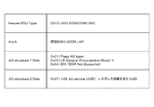
- FIG. 23 is a diagram illustrating an example of contents included in the ADV_IND advertising PDU from the terminal 200 according to the embodiment of the present invention.
- the BD_ADDR. LAP is included. Each BLE device is assigned a 48-bit address BD_ADDR.
- the MSB side 24 bits include a manufacturer identification code, and the LSB side 24 bits (LAP) includes an in-house code provided by the manufacturer.
- AD structure 1 In the Data field of the first AD structure (AD structure 1), “0x01” (“0x” means that the following number is a hexadecimal number, and so on) indicating that it is a flag group AD type.
- flag group AD type a discovery mode, an operation mode that can be advertised, and the like are represented by the following bit values.
- “Bit 1 (0x02): LE General Discoverable Mode” and “Bit” are used as devices that have a discovery mode of “General Discoverable Mode” and that do not support BR / ED other than BLE. 2 (0x04): Only BR / EDR Not Supported is set. Note that the present invention is not limited to this AD structure, and an appropriate flag can be set according to the function and operation mode supported by the terminal 200.
- AD structure 2 In the Data field of the second AD structure (AD structure 2), “0x07” indicating a 128-bit service UUID is stored at the top. The subsequent 128 bits store a service UUID representing control information.
- the format of the service UUID can be determined, for example, as follows according to UUID version 4 of RFC-4122. xxxxxxxx-xxxx-4xxxx-8xzz-zzzzzzzzzzzzzz Here, each digit is 4 bits. “4” represents the UUID version. The upper 3 bits of “8” are a variant that determines the internal layout of the UUID.
- control information is allocated to an 8-octet (64-bit) area of “x”, and the “z” area is fixed to a specific value. From the fixed value of “z”, it can be recognized that it is the service UUID of the present invention, and the value of the part of “x” can be recognized as control information. If necessary, an area larger than 64 bits may be allocated for control information.
- FIG. 24 is a diagram showing a data format example of the control information in the embodiment of the present invention.
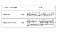
- ID 8 bits indicates the type of control message.
- REQ_STATE When the ID indicates 0xFE, it becomes REQ_STATE as shown in FIG. In the case of REQ_STATE, this indicates that a request for status reporting is made to the control target lighting device 100 represented by Flag (1 bit) and DevAddr / DeviceID (24 bits) by a response message LIGHT_STATE.
- REQ_LIGHT_CONTROL When the ID indicates 0xFD, as shown in FIG. 25, REQ_LIGHT_CONTROL is obtained. In the case of REQ_LIGHT_CONTROL, the LightValue and LightColor or DeviceID.
- the control target lighting device 100 represented by Flag and DevAddr / DeviceID. It is controlled by the control value indicated by the UsecaseID, and indicates that a status report is requested by a response message LIGHT_STATE.
- DevAddr and DeviceID share the same area exclusively, and the value of Flag indicates which value is stored in the area.
- DevAddr is BD_ADDR. Represents LAP.
- the flag is “1”
- the device ID is used as information for identifying the plurality of lighting devices 100.
- DeviceID Group (16 bits) indicates a value (group ID) for designating a specific set to which lighting device 100 belongs when the value is not “0x0000”.
- DeviceID The value of UsaseID (8 bits) from 0x01 to 0xFF represents a value for identifying use case settings.
- DeviceID The value of Group is held as a group ID, and DeviceID.
- the lighting device 100 that holds the use case setting whose ID is the value of UsecaseID is a control target.
- DeviceID If the value of UsecaseID is 0x00, DeviceID. All the illumination devices 100 having the group value as the group ID are controlled.
- DeviceID When the value of Group is “0x0000”, it is handled as follows assuming that there is no group designation by the group ID. That is, DeviceID. When UsaseID is 0x00, all the lighting devices 100 are controlled. In addition, DeviceID. When the value of UsecaseID is 0x01 to 0xFF, DeviceID. All of the lighting devices 100 that hold use case settings that use the value of UsecaseID as the ID are controlled.
- Light control and color control are controlled by the control message LightValue and LightColor, or DeviceID. This is performed based on the value of UsaseID.
- Flag is “0”, or if Flag is “1” and DeviceID.
- UsaseID is “0x00”, LightValue and LightColor are referred to.
- LightValue (4 bits) is a field for instructing the control state of the lighting device 100 in the control message.
- the value 0x00 is extinguished, the value 0x0F is all lights, and the values 0x01 to 0x0E represent the dimming values.
- LightColor (4 bits) is a field for indicating the light color of the lighting device 100 in the control message.
- the color can be controlled by the light quantity ratio.
- each of the lighting devices 100 stores a plurality (1 to 16) of light quantity ratios, a specific light quantity ratio indexed by the value of LightColor (0x00 to 0x0F), and the LightValue.
- the light quantity of each LED illumination of RGB is determined by the dimming quantity.
- the lighting device 100 performs control based on the dimming value and the toning value associated with the use case having the value of UsecaseID as the ID.
- the dimming value and the toning value are information having the same contents as LightValue and LightColor in the control message.
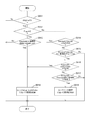
- FIG. 26 is a flowchart illustrating an example of a processing procedure of control content determination in the lighting device 100 according to the embodiment of the present invention.
- the lighting device 100 determines whether or not it is a control target and determines the control content. If the ID indicates a value other than 0xFD (step S911: No), this process is terminated, and the process proceeds to a process for a message with another ID.
- step S912 When Flag is “0” (step S912: Yes), DevAddr is BD_ADDR. It is determined whether or not it matches with the LAP. If it does not match (step S913: No), this process ends. If they match (step S913: Yes), the lighting device 100 is controlled in accordance with the LightValue and the LightColor (step S918).
- step S912 If Flag is “1” (step S912: No), DeviceID. If the group is other than “0x0000” (step S914: No) and does not match the group ID set in itself (step S915: No), this process is terminated. On the other hand, DeviceID. Group is “0x0000” (step S914: Yes), or DeviceID. When the group is other than “0x0000” (step S914: No) and matches the group ID set to itself (step S915: Yes), the following processing is continued.
- step S916: Yes the lighting device 100 is controlled in accordance with the LightValue and the LightColor (step S918).
- DeviceID. The use ID is other than “0x00” (step S916: No), and DeviceID.
- step S917: Yes the lighting device 100 is controlled according to the use case setting (step S919).
- step S917: No the Use case setting
- step S917: No the UsecaseID. Even if the UsecaseID is other than “0x00” (step S916: No), the DeviceID. If the use case with the ID of the Usecase ID is not set for itself (step S917: No), the process ends.
- FIG. 27 is a diagram illustrating an example of contents included in the ADV_NONCONN_IND advertising PDU from the illumination device 100 according to the embodiment of the present invention.
- the ADV_NONCONN_IND advertising PDU is indicated by “0010” in the PDU type of the header as described above.
- the BD_ADDR. LAP is included.
- AD structure 1 for example, the same flag group AD type data as the above-described ADV_IND advertising PDU transmitted from the terminal 200 is set.
- AD structure 2 In the Data field of the second AD structure (AD structure 2), “0x07” indicating a 128-bit service UUID is stored at the top. The subsequent 128 bits store a service UUID representing response information. The format of the service UUID is the same as the service UUID representing the control information described above. Therefore, response information is assigned to 64 bits of the 128-bit UUID.
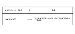
- FIG. 28 is a diagram showing a data format example of response information in the embodiment of the present invention.
- ID 8 bits indicates the response type. As shown in FIG. 29, when the ID indicates 0x00, it becomes LIGHT_STATE. In the case of LIGHT_STATE, it represents a response to REQ_STATE or REQ_LIGHT_CONTROL, or a status notification issued in response to an operation instruction from the operation reception unit 111.
- LightValue (4 bits) is a field for indicating a control state relating to the dimming value of the lighting device 100 in the response, and is information having the same contents as the field of the same name in the control message.
- LightColor (4 bits) is a field for indicating a control state related to the toning value of the lighting device 100 in the response, and is information having the same contents as the field of the same name in the control message.
- DevAddr (24 bits) is the BD_ADDR. Represents the value of LAP. Based on this value, the terminal 200 identifies the lighting device 100 that has responded.
- DeviceID 24 bits
- the value specified in the DeviceID field of the control message when the flag of the control message is “1” is stored as it is.
- the flag is “0”, or in the case of a status notification issued in response to an operation instruction from the operation reception unit 111, “0x000000” is stored in the DeviceID (24 bits).
- the value of DeviceID of the response message allows the terminal 200 to identify the control information group and use case designation that the lighting device 100 determines to be the control target.
- the DeviceID of the response information When the value of the UsecaseID is “0x01” to “0xFF”, the DeviceID. Is stored in the LightValue field and the LightColor field. The dimming value and the toning value associated with the use case, which are set in the lighting device 100 having the value of UsaseID as an ID, are set.
- FIG. 30 is a diagram illustrating an application example to BLE when an operation is performed in the specific lighting device 100 according to the embodiment of the present invention.
- the lighting device 100 When an operation input is performed by an operation member other than wireless in any of the lighting devices 100, the lighting device 100 transmits a response message with an ID of LIGHT_STATE, so that the lighting device 100 is always in the latest control state at the terminal 200. Can be grasped.
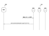
- FIG. 31 is a diagram illustrating an application example to BLE when data is set from the terminal 200 to the lighting apparatus 100 according to the embodiment of the present invention.
- access to information that is less frequently accessed from the terminal 200 is not advertising but is a service-character of GATT (Generic ATTribute Profile) It is realized by data exchange by the service (Service-Characteristic).
- GATT Generic ATTribute Profile
- Service-Characteristic Service-Characteristic
- the terminal 200 Prior to the setting operation by GATT, the terminal 200 requests the lighting apparatus 100 to start a Peripheral role of GAP (General Access Profile) and advertise to the lighting device 100 by an ADV_IND control message (REQ_PERIPHERAL). Thereafter, the terminal 200 behaves as a central role of GAP.
- GAP General Access Profile
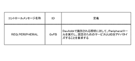
- ADV_IND control message REQ_PERIPHERAL
- the data format of the ADV_IND control message is as shown in FIG. 24.
- the ID indicates 0xFB, it becomes REQ_PERIPHERAL.
- REQ_PERIPHERAL indicates that the lighting device 100 identified by DevAddr in the format of FIG. 24 is requested to start the GAP Peripheral role and advertise the service UUID for setting.
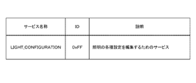
- the lighting device 100 specified in the REQ_PERIPHERAL advertisement message starts a Peripheral role of GAP, and advertises a service UUID (LIGHT_CONFIGURATION) for setting by ADV_IND advertising PDU.
- a service UUID LIGHT_CONFIGURATION
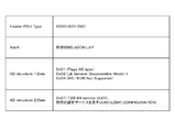
- FIG. 33 is a diagram illustrating an example of contents included in the ADV_IND advertising PDU from the lighting device 100 that transmits the setting service in the embodiment of the present invention.
- the BD_ADDR. LAP is included.
- the first AD structure (AD structure 1) is the same as the ADV_NONCONN_IND advertising PDU issued from the lighting device 100 in FIG.
- AD structure 2 In the Data field of the second AD structure (AD structure 2), “0x07” indicating a 128-bit service UUID is stored at the top.
- the subsequent 128 bits store a service UUID representing a setting service of the lighting device 100.
- the format of the service UUID is the same as the service UUID representing the response information described above. Therefore, a value indicating the setting service is assigned to 64 bits of the 128-bit UUID.
- the service UUID representing this setting service has the same format as the response information described with reference to FIG. 34, when the ID indicates 0xFF, it becomes LIGHT_CONFIGURATION. In the case of LIGHT_CONFIGURATION, the lighting device 100 is set. In this LIGHT_CONFIGURATION, all the fields other than the ID in FIG. 28 are set to “0”.
- the terminal 200 that has received the ADV_IND advertising PDU in which LIGHT_CONFIGURATION is stored establishes a connection on the data channel between the terminal 200 and the lighting device 100 by a BLE connection sequence starting from CONNECT_REQ advertising, and the GATT service of the lighting device 100 -Obtain and set the setting data of the lighting device 100 using the characteristic.
- the UUID of the service provided by the lighting device 100 is the value of LIGHT_CONFIGURATION described above.
- the characteristic UUID format can be determined, for example, as follows according to UUID version 4 of RFC-4122. xxxxzzzz-zzzz-4zzzz-8zzzz-zzzzzzzzzzzzzzzzzzzz Here, each digit is 4 bits. In this embodiment, the “z” region is fixed to a specific value. An ID value defined below is designated in the 2-octet area of “x”. That is, a characteristic ID value is assigned to the first 16 bits of the 128-bit UUID.
- GATT a characteristic is provided for each of one or more services on the server. Necessary processing is performed by writing or reading a characteristic value from the client. In this example, the following characteristics are provided for the LIGHT_CONFIGURATION service of the lighting device 100.
- the terminal 200 performs data acquisition setting by reading or writing these characteristic values.
- FIG. 35 is a diagram showing an example of a list of characteristics provided by the LIGHT_CONFIGURATION service for data setting in the embodiment of the present invention. These characteristic values may be held in the state holding unit 140, for example.
- the value of the GROUP_ID characteristic (ID: 0xFF01) is the value of the group ID set in the lighting device 100. This value is the DeviceID. Of the control information and response information. This is a 16-bit value used as the value of the Group field. This characteristic corresponds to both reading and writing. When the value of this characteristic is 0, it indicates that no group is designated.
- the value of USECASES characteristic (ID: 0xFF02) is a list of use case setting IDs held by the lighting device 100. Each use case ID in this list is 1 octet. This characteristic corresponds to reading only. Each use case setting has a name indicating a control value and a use scene of the lighting device 100. The former is accessed by the USECASE_CONTROL_VALUE characteristic, and the latter is accessed by the USECASE_NAME characteristic.
- USECASE_ID characteristic (ID: 0xFF03) is the ID of the use case setting that is the current operation target. This characteristic corresponds to both reading and writing.
- the valid range of use case ID values is “0x01” to “0xFF”.
- the value of the USECASE_CONTROL_VALUE characteristic (ID: 0xFF04) is a control value of the lighting apparatus 100 associated with the use case selected by the USECASE_ID characteristic. This is a total 8-bit value corresponding to the LightValue field and the LightColor field of the control information and response information.
- the USECASE_CONTROL_VALUE characteristic corresponds to both reading and writing.
- USECASE_NAME characteristic (ID: 0xFF05) is a character string of a name representing a use scene associated with the use case selected by the USECASE_ID characteristic. This USECASE_NAME characteristic corresponds to both reading and writing.
- USECASE_ADD characteristic (ID: 0xFF06) is a list of use case setting IDs to be newly added. Each use case ID in this list is 1 octet. This characteristic corresponds only to writing. If there is a writing in this characteristic, the lighting device 100 will use a default control value (for example, if there is no use case of the same ID value in its lighting device 100 for each ID in the written list. : 0) is generated and stored. When the use case setting is added, the ID is added to the ID list read out next time by the USECASES characteristic.
- USECASE_DEL characteristic (ID: 0xFF07) is a list of IDs of use case settings to be deleted. Each use case ID in this list is 1 octet. This characteristic corresponds only to writing.
- the lighting device 100 deletes each use case setting whose ID value is a value in the written list.
- the ID is deleted from the ID list that is read next time by the USECASES characteristic.
- the value of the LIGHT_COLOR_ID characteristic (ID: 0xFF08) is an ID value that identifies the light color of the current operation target. This is a value corresponding to the LightColor field of the control information. This characteristic corresponds to both reading and writing. By writing a specific ID value in this characteristic, the light color setting associated with that ID can be accessed via the LIGHT_COLOR_VALUE characteristic.
- the value of the LIGHT_COLOR_VALUE characteristic (ID: 0xFF09) is a value representing the RGB light quantity ratio that is associated with the ID selected by the LIGHT_COLOR_ID characteristic.
- the LIGHT_COLOR_VALUE characteristic corresponds to both reading and writing.
- the lighting device 100 and the terminal 200 perform high-speed control in a short time by performing bidirectional connectionless communication, and in any of the plurality of terminals 200.
- the latest state of the lighting device 100 can be grasped.
- the processing procedure described in the above embodiment may be regarded as a method having a series of these procedures, and a program for causing a computer to execute these series of procedures or a recording medium storing the program. You may catch it.
- a recording medium for example, a CD (Compact Disc), an MD (MiniDisc), a DVD (Digital Versatile Disc), a memory card, a Blu-ray disc (Blu-ray (registered trademark) Disc), or the like can be used.
Landscapes
- Engineering & Computer Science (AREA)
- Computer Networks & Wireless Communication (AREA)
- Human Computer Interaction (AREA)
- Automation & Control Theory (AREA)
- Signal Processing (AREA)
- Circuit Arrangement For Electric Light Sources In General (AREA)
- Selective Calling Equipment (AREA)
- General Engineering & Computer Science (AREA)
Priority Applications (4)
| Application Number | Priority Date | Filing Date | Title |
|---|---|---|---|
| EP14837848.2A EP3038293A4 (en) | 2013-08-21 | 2014-08-05 | LIGHTING CONTROL SYSTEM, END TERMINAL AND LIGHTING CONTROL METHOD THEREFOR |
| CN201480045636.6A CN105659702A (zh) | 2013-08-21 | 2014-08-05 | 照明控制系统、终端及其照明控制方法 |
| KR1020157036170A KR20160013121A (ko) | 2013-08-21 | 2014-08-05 | 조명 제어 시스템, 단말 및 그 조명 제어 방법 |
| US15/048,939 US20160174346A1 (en) | 2013-08-21 | 2016-02-19 | Lighting control system, terminal, and lighting control method thereof |
Applications Claiming Priority (2)
| Application Number | Priority Date | Filing Date | Title |
|---|---|---|---|
| JP2013170885A JP2015041438A (ja) | 2013-08-21 | 2013-08-21 | 照明制御システム、端末およびその照明制御方法 |
| JP2013-170885 | 2013-08-21 |
Related Child Applications (1)
| Application Number | Title | Priority Date | Filing Date |
|---|---|---|---|
| US15/048,939 Continuation US20160174346A1 (en) | 2013-08-21 | 2016-02-19 | Lighting control system, terminal, and lighting control method thereof |
Publications (1)
| Publication Number | Publication Date |
|---|---|
| WO2015025707A1 true WO2015025707A1 (ja) | 2015-02-26 |
Family
ID=52483487
Family Applications (1)
| Application Number | Title | Priority Date | Filing Date |
|---|---|---|---|
| PCT/JP2014/070563 WO2015025707A1 (ja) | 2013-08-21 | 2014-08-05 | 照明制御システム、端末およびその照明制御方法 |
Country Status (7)
Cited By (2)
| Publication number | Priority date | Publication date | Assignee | Title |
|---|---|---|---|---|
| JP2017005411A (ja) * | 2015-06-08 | 2017-01-05 | 株式会社タニタ | 中央装置、周辺装置、通信システム、通信方法およびプログラム |
| EP3443814A4 (en) * | 2016-04-11 | 2019-10-30 | Lark, Jr., William | LIGHT SYNCHRONIZATION DEVICES, SYSTEMS AND METHOD FOR INTELLIGENT LIGHTING CONTROL |
Families Citing this family (29)
| Publication number | Priority date | Publication date | Assignee | Title |
|---|---|---|---|---|
| TWI611379B (zh) * | 2015-03-27 | 2018-01-11 | 寶貝安科技股份有限公司 | 遙控燈具方法 |
| TWI603178B (zh) * | 2015-04-22 | 2017-10-21 | 富奇想股份有限公司 | 連接裝置 |
| TWI569685B (zh) * | 2015-04-28 | 2017-02-01 | 普晶材料股份有限公司 | 燈具控制設定方法及執行該方法之電腦程式產品 |
| KR101727549B1 (ko) | 2015-06-18 | 2017-04-17 | 주식회사 하남아트텍 | 무선 조명 제어 시스템 |
| WO2016208577A1 (ja) * | 2015-06-22 | 2016-12-29 | シャープ株式会社 | 携帯端末及びプログラム |
| EP3354006A4 (en) * | 2015-09-22 | 2019-05-08 | Nokia Technologies Oy | SYNCHRONIZATION OF MULTIMEDIA STREAMS |
| US10057966B2 (en) * | 2016-04-05 | 2018-08-21 | Ilumisys, Inc. | Connected lighting system |
| CN105934047B (zh) * | 2016-04-20 | 2019-03-22 | 北京小米移动软件有限公司 | 一种控制智能灯的方法、装置及系统 |
| US10588202B1 (en) * | 2016-05-02 | 2020-03-10 | Technology For Humankind Llc | Communicative lighting systems |
| JP2018005977A (ja) * | 2016-06-27 | 2018-01-11 | Quicco Sound株式会社 | 照明装置制御システム及び照明装置制御方法 |
| CN114666771A (zh) | 2016-07-20 | 2022-06-24 | 德克斯康公司 | 用于葡萄糖数据的无线通信的系统和方法 |
| JP6814385B2 (ja) * | 2016-09-01 | 2021-01-20 | 東芝ライテック株式会社 | 制御装置、機器、システム及びプログラム |
| US10313861B2 (en) * | 2016-09-15 | 2019-06-04 | WiSilica Inc. | Wireless control of multiple actor devices by multiple controller devices with communication security |
| WO2018148587A1 (en) * | 2017-02-10 | 2018-08-16 | Selevan James R | Portable electronic flare carrying case and system |
| EP3869875A1 (en) | 2017-06-01 | 2021-08-25 | Signify Holding B.V. | Determining a duty schedule for a group of electronic service-providing devices providing a similar audio and/or video service |
| CA3080621A1 (en) * | 2017-10-26 | 2019-05-02 | Racepoint Energy, LLC | Intelligent lighting control system secure connection control apparatuses, systems, and methods |
| KR102008267B1 (ko) * | 2017-12-12 | 2019-08-07 | 엘지전자 주식회사 | 라이팅 장치 및 이를 포함하는 공연 시스템 |
| JP7246003B2 (ja) * | 2018-11-09 | 2023-03-27 | パナソニックIpマネジメント株式会社 | 照明システム、照明システムの通信方法、および、プログラム |
| JP7246016B2 (ja) * | 2018-12-28 | 2023-03-27 | パナソニックIpマネジメント株式会社 | 通信方法、プログラムおよび通信装置 |
| JP2020115437A (ja) * | 2019-01-18 | 2020-07-30 | パナソニックIpマネジメント株式会社 | 照明システム、端末装置、及びプログラム |
| JP7300620B2 (ja) * | 2019-01-18 | 2023-06-30 | パナソニックIpマネジメント株式会社 | 照明システム、端末装置、及びプログラム |
| CN113841282B (zh) * | 2019-09-17 | 2024-06-28 | 株式会社东芝 | 蓄电池装置 |
| JP7365692B2 (ja) * | 2019-12-25 | 2023-10-20 | パナソニックIpマネジメント株式会社 | 照明システム及びその制御方法 |
| KR102471426B1 (ko) * | 2020-03-16 | 2022-11-25 | 이광희 | Ble 메쉬 그룹 설정이 가능한 스마트 조명 장치 및 이를 이용한 조명 제어 방법 |
| JP7175025B2 (ja) | 2020-11-20 | 2022-11-18 | 株式会社アットロボティクス | 情報処理装置、情報処理システム、情報処理方法及びプログラム |
| CN116724196A (zh) * | 2021-01-20 | 2023-09-08 | 博克希斯株式会社 | 灯和系统 |
| CN115914097B (zh) * | 2021-08-11 | 2025-01-07 | 深圳智岩科技股份有限公司 | 控制发光设备的方法及相关设备 |
| JP7561720B2 (ja) * | 2021-09-30 | 2024-10-04 | 株式会社遠藤照明 | 照明制御用リモコン及び照明システム |
| WO2023129593A1 (en) | 2021-12-29 | 2023-07-06 | Selevan Adam Jordan | Vehicular incursion alert systems and methods |
Citations (4)
| Publication number | Priority date | Publication date | Assignee | Title |
|---|---|---|---|---|
| JP2004030933A (ja) * | 2002-06-21 | 2004-01-29 | Hitachi Ltd | 照明制御装置 |
| JP2005183274A (ja) * | 2003-12-22 | 2005-07-07 | Doshisha | 照明制御システム |
| JP2010198877A (ja) | 2009-02-24 | 2010-09-09 | Panasonic Electric Works Co Ltd | 照明制御システム |
| JP2011129481A (ja) * | 2009-12-21 | 2011-06-30 | Panasonic Electric Works Co Ltd | 照明システム |
Family Cites Families (6)
| Publication number | Priority date | Publication date | Assignee | Title |
|---|---|---|---|---|
| US20040240451A1 (en) * | 2003-05-30 | 2004-12-02 | Koon-Seok Lee | Connection handling, service management, and channel handling devices of home network management system |
| US20090160626A1 (en) * | 2005-02-24 | 2009-06-25 | Lg Electronics Inc. | Method for Setting Home Code in Network System and Device for Network |
| FR2956757B1 (fr) * | 2010-02-25 | 2012-09-21 | Somfy Sas | Affectation de scenarios a des boutons de commande. |
| SG175481A1 (en) * | 2010-05-03 | 2011-11-28 | Guan Hong Tan | System and method for automatic appliance management |
| EP2515610A1 (en) * | 2011-04-19 | 2012-10-24 | Samsung LED Co., Ltd. | Method, system and apparatus for controlling light |
| CN102571162B (zh) * | 2011-12-15 | 2014-02-12 | 重庆大学 | 基于广播数据包的跳绳过程数据传输方法 |
-
2013
- 2013-08-21 JP JP2013170885A patent/JP2015041438A/ja not_active Withdrawn
-
2014
- 2014-08-05 EP EP14837848.2A patent/EP3038293A4/en not_active Withdrawn
- 2014-08-05 KR KR1020157036170A patent/KR20160013121A/ko not_active Withdrawn
- 2014-08-05 CN CN201480045636.6A patent/CN105659702A/zh active Pending
- 2014-08-05 WO PCT/JP2014/070563 patent/WO2015025707A1/ja active Application Filing
- 2014-08-15 TW TW103128173A patent/TW201513731A/zh unknown
-
2016
- 2016-02-19 US US15/048,939 patent/US20160174346A1/en not_active Abandoned
Patent Citations (4)
| Publication number | Priority date | Publication date | Assignee | Title |
|---|---|---|---|---|
| JP2004030933A (ja) * | 2002-06-21 | 2004-01-29 | Hitachi Ltd | 照明制御装置 |
| JP2005183274A (ja) * | 2003-12-22 | 2005-07-07 | Doshisha | 照明制御システム |
| JP2010198877A (ja) | 2009-02-24 | 2010-09-09 | Panasonic Electric Works Co Ltd | 照明制御システム |
| JP2011129481A (ja) * | 2009-12-21 | 2011-06-30 | Panasonic Electric Works Co Ltd | 照明システム |
Non-Patent Citations (1)
| Title |
|---|
| See also references of EP3038293A4 |
Cited By (2)
| Publication number | Priority date | Publication date | Assignee | Title |
|---|---|---|---|---|
| JP2017005411A (ja) * | 2015-06-08 | 2017-01-05 | 株式会社タニタ | 中央装置、周辺装置、通信システム、通信方法およびプログラム |
| EP3443814A4 (en) * | 2016-04-11 | 2019-10-30 | Lark, Jr., William | LIGHT SYNCHRONIZATION DEVICES, SYSTEMS AND METHOD FOR INTELLIGENT LIGHTING CONTROL |
Also Published As
| Publication number | Publication date |
|---|---|
| KR20160013121A (ko) | 2016-02-03 |
| CN105659702A (zh) | 2016-06-08 |
| US20160174346A1 (en) | 2016-06-16 |
| TW201513731A (zh) | 2015-04-01 |
| JP2015041438A (ja) | 2015-03-02 |
| EP3038293A1 (en) | 2016-06-29 |
| EP3038293A4 (en) | 2016-06-29 |
Similar Documents
| Publication | Publication Date | Title |
|---|---|---|
| WO2015025707A1 (ja) | 照明制御システム、端末およびその照明制御方法 | |
| US9949349B2 (en) | Lighting control apparatus, lighting control method, and lighting control system | |
| US8780807B2 (en) | Wireless network system with enhanced address conflict resolving functionality | |
| CN106571149B (zh) | 电子装置及电子装置的音乐内容可视化方法 | |
| US10701536B1 (en) | Quarantine network for wireless devices | |
| JP2015513188A (ja) | 制御デバイスの構成設定のための方法及び装置 | |
| US10477653B2 (en) | Notification lighting control | |
| US9961512B2 (en) | Method for operating and commissioning devices in a ZigBee network | |
| US10797944B2 (en) | Zigbee light link network commissioning | |
| CN103348771A (zh) | 用于使用低功率无线通信模块控制led照明的方法和系统 | |
| EP3323275A1 (en) | Method for configuring a device in a lighting system | |
| CN104320723A (zh) | 一种基于可见光通信的语音对讲系统 | |
| JP7600313B2 (ja) | ライティング装置統合制御方法及びライティング装置 | |
| JP6691755B2 (ja) | 通信システム、通信方法、照明制御システム、照明制御方法、及びプログラム | |
| JP2013255107A (ja) | コントローラ、制御端末、遠隔制御システムおよび通信方法をプロセッサに実行させるためのプログラム | |
| KR101976563B1 (ko) | 조명 제어 시스템에서의 조명 등록 장치 및 방법 | |
| US9839102B2 (en) | Lighting control method and lighting control system | |
| JP6979603B2 (ja) | 照明システム、照明システムのスケジュール情報送信方法、および、操作端末 | |
| JP6005406B2 (ja) | 遠隔制御システム、端末、コントローラ、および遠隔制御方法 | |
| KR101608590B1 (ko) | 조명 제어 장치 및 조명 제어 방법 | |
| JP2016062763A (ja) | 照明制御システム及び照明制御方法 | |
| JP2024107639A (ja) | 照明器具、及び、照明制御システム |
Legal Events
| Date | Code | Title | Description |
|---|---|---|---|
| 121 | Ep: the epo has been informed by wipo that ep was designated in this application |
Ref document number: 14837848 Country of ref document: EP Kind code of ref document: A1 |
|
| ENP | Entry into the national phase |
Ref document number: 20157036170 Country of ref document: KR Kind code of ref document: A |
|
| REEP | Request for entry into the european phase |
Ref document number: 2014837848 Country of ref document: EP |
|
| WWE | Wipo information: entry into national phase |
Ref document number: 2014837848 Country of ref document: EP |
|
| NENP | Non-entry into the national phase |
Ref country code: DE |