WO2015025587A1 - 鉱山車両及び鉱山車両の管理システム - Google Patents
鉱山車両及び鉱山車両の管理システム Download PDFInfo
- Publication number
- WO2015025587A1 WO2015025587A1 PCT/JP2014/065115 JP2014065115W WO2015025587A1 WO 2015025587 A1 WO2015025587 A1 WO 2015025587A1 JP 2014065115 W JP2014065115 W JP 2014065115W WO 2015025587 A1 WO2015025587 A1 WO 2015025587A1
- Authority
- WO
- WIPO (PCT)
- Prior art keywords
- mining vehicle
- road shoulder
- road
- vehicle
- mining
- Prior art date
- Legal status (The legal status is an assumption and is not a legal conclusion. Google has not performed a legal analysis and makes no representation as to the accuracy of the status listed.)
- Ceased
Links
Images








Classifications
-
- E—FIXED CONSTRUCTIONS
- E21—EARTH OR ROCK DRILLING; MINING
- E21F—SAFETY DEVICES, TRANSPORT, FILLING-UP, RESCUE, VENTILATION, OR DRAINING IN OR OF MINES OR TUNNELS
- E21F17/00—Methods or devices for use in mines or tunnels, not covered elsewhere
-
- G—PHYSICS
- G06—COMPUTING OR CALCULATING; COUNTING
- G06V—IMAGE OR VIDEO RECOGNITION OR UNDERSTANDING
- G06V20/00—Scenes; Scene-specific elements
- G06V20/50—Context or environment of the image
- G06V20/56—Context or environment of the image exterior to a vehicle by using sensors mounted on the vehicle
- G06V20/588—Recognition of the road, e.g. of lane markings; Recognition of the vehicle driving pattern in relation to the road
Definitions
- the present invention relates to a mining vehicle such as a dump truck and a management system for a plurality of mining vehicles operating in the mine.
- an object detection apparatus using a stereo camera composed of a combination of at least two cameras is also known (for example, refer to FIG.
- a mining vehicle such as a dump truck
- a stereo camera a three-dimensional image around the mining vehicle can be obtained, so that it is possible to detect the road shoulder, and the mining vehicle can easily travel along the traveling path.
- dump trucks used in mines are required to be able to operate with high efficiency because the transport amount of earth and sand per unit time is directly related to the progress of mining.
- a deviation prevention guard such as a dirt wall is provided on the shoulder of the mine traveling path to prevent the dump truck from departing from the traveling path.
- a mining vehicle is provided with a stereo camera, a three-dimensional image around the mining vehicle can be obtained, and therefore the presence or absence of a departure prevention guard that is a three-dimensional object can be detected.
- the departure prevention guard is not provided over the entire length of the traveling road, and there is a traveling road where the departure prevention guard is not yet developed.
- a departure prevention guard is not provided at the intersection of the traveling road, and a mine vehicle can be passed.
- the formed escape prevention guard may collapse.
- the present invention has been made in view of the situation of the prior art as described above, and its purpose is to determine whether or not the vehicle can run even when the departure prevention guard provided along the shoulder of the road is not detected.
- the present invention relates to a mining vehicle, a pair of left and right drive wheels attached to a vehicle body, a pair of electric motors driving each of the pair of drive wheels, and a pair of these
- a vehicle control unit that controls the driving and stopping of the electric motor, a three-dimensional sensor that three-dimensionally measures the periphery of the vehicle body, and information from the three-dimensional sensor, along the travel path and the shoulder of the travel path
- a road shoulder recognition unit for recognizing the formed departure prevention guard, a locator for measuring the current position and direction of the vehicle body, map data having information on the travel path and information on the departure prevention guard, and a position indicated by the locator
- the recognition result of the shoulder recognition unit are collated to determine whether or not they match, and a mismatch signal is output when it is determined that they do not match Characterized in that a shoulder determination unit that.
- the mining vehicle is provided with a three-dimensional sensor for three-dimensional measurement of the surroundings of the vehicle body, it is possible to detect the traveling path and the three-dimensional deviation prevention guard formed along the traveling path. Further, by processing information from the three-dimensional sensor using the road shoulder recognition unit, it can be recognized whether or not the departure prevention guard is captured in the field of view of the three-dimensional sensor. Furthermore, if the mining vehicle is provided with a locator such as a GPS, a gyro sensor, and an acceleration sensor, the current location of the mining vehicle can be detected.
- a locator such as a GPS, a gyro sensor, and an acceleration sensor
- the road shoulder determination unit can obtain the information on the map data at the current position of the mining vehicle indicated by the locator. It can be determined whether or not the recognition results of the road shoulder recognition unit match. If they match, there is no error in recognition by the road shoulder recognition unit, so that the mining vehicle can be safely driven in accordance with the map data even on the road where the departure prevention guard is not maintained.
- the road shoulder determination unit determines that the information of the map data and the recognition result of the road shoulder recognition unit do not match, for example, the departure prevention guard collapses or there is an obstacle such as another mining vehicle on the traveling road. This means that there is a situation where it is not appropriate to continue traveling the mining vehicle as it is. Therefore, the mining vehicle can be made safe by taking appropriate measures such as stopping traveling. Therefore, safe operation of the mine vehicle can be realized.
- the vehicle control unit receives the output of the mismatch signal from the road shoulder determination unit, generates a control signal for the mining vehicle, and automatically controls the mining vehicle based on the control signal. It is characterized by shifting from the running state to the stopped state.
- the vehicle control unit automatically shifts the host vehicle from the running state to the stopped state. Therefore, it is possible to ensure safe traveling of the own vehicle, particularly the unmanned mining vehicle that autonomously travels.
- the vehicle control unit receives the output of the mismatch signal from the road shoulder determination unit and generates a control signal for a monitor provided in a driver seat of the mine vehicle.
- the determination result of the road shoulder recognition unit is displayed on the monitor by a control signal.
- the vehicle control unit recognizes the road shoulder on the monitor provided in the driver's seat of the own vehicle. Since the determination result of the unit is displayed, the driver can be informed of the occurrence of abnormality, and safe driving can be ensured for the manned mining vehicle.
- the mining vehicle having the above-described configuration further includes a communication device that wirelessly transmits the mismatch signal to the outside.
- the road shoulder determination unit determines that the information on the map data at the position indicated by the locator and the recognition result of the road shoulder recognition unit do not match
- the other vehicle (following vehicle) following the own vehicle or the mining vehicle This can be transmitted to a management center that centrally manages operations.
- the management center can transmit a required command signal created in response to the mismatch signal to other mining vehicles operating in the mine. Therefore, a plurality of mining vehicles operating in the mine can share information on the safety of the traveling path, and the safety of the entire mine can be improved.
- the map data includes information related to an intersection
- the road shoulder determination unit indicates an intersection at a position on the map data corresponding to the position indicated by the locator.
- a departure prevention guard is not formed at the intersection to allow mine vehicles to pass. Therefore, when the mining vehicle is in the intersection, even if the road shoulder recognition unit does not recognize the departure prevention guard, the information of the map data and the recognition result of the road shoulder recognition unit are determined to be the same, thereby smoothing the mining vehicle. Can be ensured.
- the road shoulder determination unit stores in advance a threshold value related to the height of the departure prevention guard formed along the road shoulder of the traveling road, and the road shoulder recognition unit acquires the threshold value. Based on the height information of the departure prevention guard and the threshold value, it is determined whether or not the height of the departure prevention guard acquired by the road shoulder recognition unit is normal.
- the road shoulder determination unit can determine not only the presence or absence of the departure prevention guard formed along the road shoulder of the traveling road but also whether or not the height is normal. If it is determined that the height of the departure prevention guard is abnormal, there is a possibility that an abnormality such as a collapse has occurred in the traveling road. Therefore, the safety of the mining vehicle can be further ensured by determining the height of the departure prevention guard.
- the road shoulder determination unit may determine whether the road shoulder needs to be repaired based on the height information of the departure prevention guard acquired by the road shoulder recognition unit and the threshold value. The determination is further performed.
- the departure prevention guard formed along the traveling path of the mining vehicle is formed at a height necessary for safe driving of the mining vehicle.
- a threshold value related to the height of the departure prevention guard formed along the shoulder of the road is stored in advance, and the height information of the departure prevention guard acquired by the road shoulder recognition unit is compared with the threshold value. For example, it can be determined whether or not the height of the departure prevention guard is maintained at a height necessary for safe driving of the mining vehicle, that is, whether or not the road shoulder needs to be repaired. Therefore, since the road shoulder can be repaired based on the determination result, the maintenance management of the traveling path of the mining vehicle can be facilitated.
- the present invention comprises a mining vehicle management system comprising a plurality of mining vehicles traveling on a road and a management center that centrally manages the operations of the plurality of mining vehicles using a control system,
- the mining vehicle uses a three-dimensional sensor that three-dimensionally measures the periphery of the vehicle body, and roadside recognition that recognizes a travel path and a departure prevention guard formed along the shoulder of the travel path using information from the three-dimensional sensor.
- a locator for measuring the current position and direction of the vehicle body, map data having information on the traveling road and information on the departure prevention guard, information on the map data at the position indicated by the locator, and the road shoulder recognition unit A road shoulder determination unit that outputs a mismatch signal when it is determined that they do not match, and determines whether or not they match.
- a control device that transmits a match signal to the outside, and when the control system of the management center receives a mismatch signal from the communication device, the control system of the control center A command signal for automatically shifting the mining vehicle from the running state to the stopped state, or a command signal for displaying the mismatch signal on a monitor provided in a driver seat of the other mining vehicle.
- the determination result is transmitted to the control system of the management center.
- the control system of the management center transmits a required command signal to other mining vehicles traveling on the road based on the determination result, so that other mining vehicles operating in the mine Information can be shared, and the safety of mining vehicles can be secured throughout the mine.
- the control system of the management center stores in advance a range in which the command signal is to be transmitted, and the mismatch signal is transmitted from one mining vehicle.
- the command signal is selectively transmitted to another mining vehicle following the one mining vehicle, the mining vehicle existing within a range in which the command signal is to be transmitted.
- the one that is directly affected by the abnormality is the one mining vehicle and one or more subsequent to it. It does not necessarily affect all mining vehicles operating in the mine. Therefore, when one mining vehicle determines that the information of the map data and the recognition result of the shoulder recognition unit do not match, the determination result is transmitted to the control system of the management center, and the control system of the management center stores the range stored in advance. By transmitting a required command signal to the succeeding mining vehicle, it is possible to ensure the safety of the mining vehicle within a necessary range.
- the present invention it is possible not only to recognize the presence or absence of the departure prevention guard formed along the shoulder of the traveling road, but also to safely run the mining vehicle when the departure prevention guard cannot be recognized. Since it is further determined whether or not it is possible, the mining vehicle can be operated safely and efficiently.
- a dump truck (work vehicle) 10 includes a vehicle body 1, a cab 2 and a vessel 3 installed on the vehicle body 1, and a pair of left and right attached to the vehicle body 1.
- a drive wheel 4 and a pair of electric motors 4a for driving each of the pair of drive wheels 4 are provided.
- the dump truck 10 may be an unmanned driving vehicle that autonomously travels, or may be a manned driving vehicle that is driven by an operator operating a driving device (not shown) provided in the cab 2.
- An external recognition device 20 is mounted on the vehicle body 1.
- symbol 5 in a figure shows the headlamp of the dump truck 10, and the code
- the external environment recognition device 20 includes a stereo camera device (three-dimensional sensor) 210, a distance information calculation unit 220, a traveling road surface detection unit 221, a road shoulder recognition unit 222, a road shoulder determination unit 230, The map data 240, the locator 250, the vehicle control unit 270, and the external communication device 280 are provided.
- the stereo camera device 210 includes at least two cameras (two on the left and right in the example of FIG. 1) arranged in parallel, with the optical axis of each camera directed in the forward direction of the dump truck 10 on the vehicle body 1. Installed.
- the distance information calculation unit 220 acquires image data in the forward direction of the dump truck 10 captured by the left and right cameras of the stereo camera device 210, converts these image data into three-dimensional information, and captures the captured three-dimensional object. The distance information is calculated. The function of the distance information calculation unit 220 will be described later with reference to FIGS. 2 to 5 and FIGS.
- the traveling road surface detection unit 221 detects a road surface portion of the traveling road on which the dump truck 10 can travel from the three-dimensional information obtained by the distance information calculation unit 221.
- the road surface detection procedure by the traveling road surface detection unit 221 will be described later with reference to FIG.
- the road shoulder recognition unit 222 recognizes a three-dimensional object at a road edge having a predetermined height as compared with the road surface detected by the traveling road surface detection unit 221 as a road shoulder.
- the road shoulder recognition of the present embodiment since a dirt wall formed by raising earth and sand is usually provided along the road shoulder as a departure prevention guard for preventing the departure of the dump truck 10 from the traveling road, the road shoulder recognition of the present embodiment.
- the unit 222 recognizes the presence / absence, position, height, and the like of a dirt wall.
- a dirt wall is formed as a departure prevention guard will be described as an example.
- a case where a three-dimensional object other than the dirt wall, for example, a guide rail or a curb is installed is recognized by the same procedure.
- the map data 240 is obtained by editing the information on the travel path of the dump truck 10 excavated in the mine in the form of electronic data. For all the travel paths, information on the earth wall, for example, the earth wall formation section and its The height dimension etc. are described. Further, in the map data 240, when there is an intersection on the traveling road, information on the intersection, for example, the position of the intersection, the road width of each intersecting traveling road, and the like are also described.
- the locator 250 measures the current position of the dump truck 10 and the direction of the traveling direction.
- the locator 250 includes a GPS 2510, a gyro sensor 2520, and an acceleration sensor 2530.
- the GPS 2510 outputs the position of the dump truck 10 as latitude and longitude information.
- the gyro sensor 2520 outputs a direction indicating the traveling direction of the dump truck 10.
- the acceleration sensor 2530 is used for estimation of a position interpolated between the measurement periods of the GPS 2510, and estimation of a position when the GPS 2510 receives a radio wave from a satellite poorly.
- the road shoulder determination unit 230 collates the recognition result of the road shoulder recognition unit 222 with the information on the earth wall described in the position on the map data 240 corresponding to the current position of the dump truck 10 indicated by the locator 250, and these match. Or not. A specific determination example will be described later with reference to FIG.
- the road shoulder determination unit 230 outputs a mismatch signal to the vehicle control unit 270 and the external communication device 280 when it is determined that the recognition result of the road shoulder recognition unit 222 and the information about the earth wall described in the map data 240 do not match. To do.
- the vehicle control unit 270 When the vehicle control unit 270 receives the mismatch signal from the road shoulder determination unit 230, the vehicle control unit 270 generates a required control signal, and the vehicle body 1 provided in the dump truck 10 and an engine and monitor 6 (not shown) mounted on the vehicle body 1. Etc. are controlled. Thereby, since the required operation
- a vehicle body controller, an engine controller, a display controller, or the like mounted on the vehicle body 5 can be used.
- the host vehicle can be automatically stopped based on the determination result of the road shoulder determination unit 230. Safe driving can be ensured for unmanned mining vehicles that run autonomously.
- a control signal for displaying the determination result of the road shoulder recognition unit 222 is output from the vehicle control unit 270 to the monitor 6, it is possible to notify the driver of the occurrence of an abnormality, so that safe driving can be performed for a manned mining vehicle. Can be secured.
- the external communication device 280 transmits a required data signal including the mismatch signal to the management center that manages the operation of all the mining vehicles operating in the mine.
- the management center that manages the operation of all the mining vehicles operating in the mine.
- the distance information calculation unit 220 first, in S100, image data picked up by the stereo camera device 210 is input (procedure). Next, proceeding to S110, the left and right images acquired in S100 are compared, and corresponding points of the same object are calculated and specified. That is, as shown in FIG. 3, when a three-dimensional earth wall (deviation prevention guard) 320 formed on the shoulder of the traveling road 300 is imaged by the stereo camera device 210, the images are captured by the left and right imaging units 211 and 212. The images are like a right image 340 and a left image 341, respectively.
- the specific point on the earth wall imaged at the position indicated by reference numeral 343 in the left image 341 is determined as the right image. It is necessary to specify at which position of 340 the image is captured.
- the correlation value between the image in the rectangular area 355 and the image in the rectangular area 353 is compared, and the position of the rectangular area 354 of the right image 340 having the highest correlation with the rectangular area 355 of the left image 341 is extracted.
- the positions of the rectangular region 354 of the right image 340 having the highest correlation with the rectangular region 355 of the left image 341 are (u4, v1), (u4, v2), (u4 + (u2 ⁇ u1), v1) and (u4 + (u2-u1), v2).
- each pixel in the rectangular area 354 to which each pixel in the rectangular area 355 corresponds can be obtained.
- the rectangular area of the left image 341 is shifted to the position 356, and the same processing is performed. Further, after the operation in the u direction is completed, the same processing is performed for the rectangular area set in the v direction. In this way, corresponding points in the right image 340 are obtained for all the pixels of the left image 341. If no corresponding point is found, there is no corresponding point.
- the process returns to the flowchart of FIG. 2 and the distance calculation process of S120 is performed.
- S120 the distance from the stereo camera device 210 is calculated regarding the corresponding points of the left image 341 and the right image 340 obtained in S110.
- the left imaging unit 211 is a camera with a focal length f in which a lens 405 and an imaging surface 409 are arranged on the optical axis 403, and the right imaging unit 212 is configured such that the lens 404 and the imaging surface 408 are optical axes 402. It is a camera with a focal length f arranged on the top.
- a point 401 in front of each camera is imaged to a point 407 (distance from the optical axis 403 to d2) on the imaging surface 409 of the left imaging unit 211, and a point 407 (position of d4 pixels from the optical axis 403 to the left image 341).
- the point 401 is imaged at the point 406 (distance from the optical axis 402 to d3) on the imaging surface 408 of the right imaging unit 212, and becomes the point 406 (position of the d5 pixel from the optical axis 402) in the right image 340. .
- the point 401 on the same object is imaged at the position of d4 pixels from the optical axis 403 to the left in the left image 341, and at the position of d5 from the optical axis 402 to the right in the right image 340, resulting in a parallax of d4 + d5 pixels.
- the distance between the optical axis 403 of the left imaging unit 211 and the point 401 is x
- the distance D from the stereo camera device 210 to the point 401 can be obtained by the following equation.
- d2: f x: D is established from the positional relationship between the point 401 and the left imaging unit 211
- d3: f (d ⁇ x): D from the positional relationship between the point 401 and the right imaging unit 212.
- a is the size of the image sensor on the imaging surface 409.
- the distances calculated from the stereo camera device 210 to the corresponding points are calculated for all the corresponding points calculated in S110. Thereby, a distance image expressing the distance from the stereo camera device 210 to the object can be obtained.
- this distance image is output and stored.
- the process proceeds to S140 of the flowchart of FIG. 2 to determine whether there is an image input signal from the left imaging unit 211 and the right imaging unit 212. If it is determined in S140 that there is an image input signal from the left imaging unit 211 and the right imaging unit 212 (Yes), the process returns to S100. If it is determined in S140 that there is no image input signal from the left imaging unit 211 and the right imaging unit 212 (No), the process waits until the image input signal is input to the distance information calculation unit 220.
- the distance image output from the distance information calculation unit 220 is read.
- a three-dimensional information calculation process is performed using the distance image read in S310, and the three-dimensional position of each pixel on the screen is obtained.
- the distance dk from the stereo camera device 210 is calculated for all the pixels of the left image 341.
- a three-dimensional coordinate value (xk, yk, zk) of the imaging object 453 is calculated.
- the three-dimensional coordinates are as follows.
- the traveling direction of the vehicle is the z-axis 461
- the vertical axis of the vehicle is the z-axis 461
- the horizontal axis of the vehicle is the x-axis 460.
- the axis that is perpendicular to the z-axis and that is in the vertical direction of the vehicle is the y-axis.
- the x coordinate value xk of the imaging target 453 shown in FIG. 8 can be calculated by the following method. That is, in FIG. 9, the left imaging unit 211 is a camera with a focal length f, in which a lens 405 and an imaging surface 409 are arranged on a z ′ axis 471 that is an optical axis.
- the z axis 461 in FIG. 8 and the z ′ axis 471 in FIG. 9 are on the same plane as the plane perpendicular to the xz plane in FIG. 8, and the angle formed between the z axis 461 and the z ′ axis 471 is a stereo camera device. This coincides with the installation depression angle ⁇ of 210.
- FIG. 9 is the x ′ axis 472 including the imaging surface 409 of FIG. 9 and perpendicular to the z ′ axis 471, the x ′ axis 472 of FIG. 9 and the x axis 460 of FIG.
- the imaging target 453 in FIG. 8 is the point 470 in FIG. 9
- the point 470 is imaged at the position X2 from the optical axis 471 of the imaging surface 409.
- the size of the imaging element size in the x′-axis 472 direction on the imaging surface 409 is a
- the y coordinate value yk of the imaging target 453 shown in FIG. 8 can be calculated by the following method. That is, in FIG. 10, the left imaging unit 211 is a camera having a focal length f, in which a lens 405 and an imaging surface 409 are arranged on a z ′ axis 471 that is an optical axis.
- the z axis 461 in FIG. 10 is the same as the z axis 461 in FIG. 8, and the angle formed by the z axis 461 and the z ′ axis 471 coincides with the installation depression angle ⁇ of the stereo camera device 210.
- the point 470 is imaged at the position Y2 from the optical axis 471 of the imaging surface 409.
- the process returns to S330 in the flowchart of FIG. 6 to perform the traveling road surface type fitting process.
- a pixel having a high possibility of being a traveling road surface is extracted from each pixel of the left image 341 obtained in the three-dimensional information calculation process S320 which is the pre-processing.
- a left image 341 illustrated in FIG. 11 is an image captured by the left imaging unit 211, and the traveling road 300 is captured by the left imaging.
- the three-dimensional objects 310, 320, and 330 shown in FIG. 11 are dirt walls formed along the shoulders of the traveling road 300, and portions 602 that do not include the dirt walls 310, 320, and 330 in the vicinity of the dump truck 10. Are extracted as pixels used for running road surface type fitting.
- the traveling road surface can be obtained by calculating parameters a, b, and c that satisfy Pi by applying j and j to the number of extracted pixels).
- the operation of the shoulder recognition unit 222 shown in FIG. 1 will be described using the flowchart of FIG.
- earth walls 310, 320, and 330 having a predetermined height are formed on the shoulders of the traveling road 300. Therefore, if a three-dimensional object having a predetermined height from the road surface can be detected, the dirt wall on the road shoulder can be detected.
- the road shoulder recognition unit 222 groups solid objects having a predetermined height from the road surface at both ends of the road surface (S420). For example, as shown in FIG.
- portions that are higher than the road surface 300 by a predetermined height are grouped at both ends of the road surface 300.
- the soil walls 3101 and 3102 are portions extracted by grouping portions having a height H from the road surface 300, and are separated by a distance L in the example of FIG.
- S430 it is determined whether there is a portion where the group of three-dimensional objects existing on the left side of the road surface does not exist beyond a predetermined interval. If there is a portion that does not exist, the process proceeds to S440, and it is determined that there is no road shoulder on the left side. The same determination is performed on the right side of the road surface in S450 and S460.
- the road shoulder determination unit 230 determines whether information regarding the earth wall is written at the detection position of the three-dimensional object.
- the map data 240 indicates the travel path 300 of the dump truck 10 by links and nodes, and has a data format shown in FIG. (A) shows an example of a travel route, and it is assumed that there is a link L1 between nodes N1 and N2, a link L2 between nodes N2 and N3, and a link L3 between nodes N2 and N4. It is assumed that the dump truck 10 travels toward the vehicle. Further, a branch path L2 exists at the node N2 in the middle. Interpolation nodes are defined between the nodes in order to approximate the shape of the traveling road with a broken line.
- interpolation nodes IN1, IN2, and IN3 are defined between the node N1 and the node N2
- interpolation nodes IN6 and IN7 are defined between the node N2 and the node N4, and between the nodes N2 and N3.
- Interpolation nodes IN4 and IN5 are defined.
- the link table of (b) shows the coordinate value composed of the latitude and longitude for indicating the positions of the start point node N1 and the end point node N2, the branch point ID indicating the information of the branch point, the actual link L1 with respect to the link number L1.
- the left and right shoulder flag is in the format shown in (d).
- the shoulder attribute is 01
- the height of the road shoulder is defined by the height of the road shoulder (RH).
- the road shoulder attribute is 10
- the road shoulder attribute is 11
- it indicates that the end of the road surface is a cliff and there is no structure higher than the road surface.
- FIG. 13 shows a processing flow of the shoulder determination unit 230.
- the position information and traveling direction of the dump truck 10 are acquired from the locator 250.
- the link data of the road on which the dump truck 10 is currently traveling is read from the map data 240.
- the traveling direction of the dump truck 10 and the direction of the link information read in S520 are collated, and it is determined whether the directions match. If the heading is deviated more than a predetermined error, the road shoulder determination process is not performed. For example, this corresponds to a case where the dump truck 10 changes its direction on the road in order to avoid an obstacle (not shown) on the road.
- the process proceeds to S540, where the information on the road shoulder flag of the link data read from the map data 240 is compared with the determination result of the road shoulder recognition unit 222, and whether or not each piece of information matches or does not match. Make a decision.
- the recognition result of the road shoulder recognition unit 222 is “no dirt wall on the left side of the road surface”, and “no earth wall” is written in the left road shoulder flag of the link data, or the map data 240 is an intersection (branch node). If the road shoulder recognition unit 222 cannot recognize the earth wall, there is no abnormality in the determination result of the road shoulder recognition unit 222, so that a determination result indicating “match” is output. For example, as shown in FIG.
- the road shoulder determination unit 230 determines that the recognition result of the road shoulder recognition unit 222 does not match the information about the earth wall written in the map data 240, the road shoulder determination unit 230 transmits a mismatch signal to the vehicle control unit 270 and the external communication device 280. .
- the vehicle control unit 270 When the vehicle control unit 270 receives the mismatch signal from the road shoulder determination unit 230, the vehicle control unit 270 outputs a control signal for controlling the driving of the in-vehicle device in order to avoid the danger of the own vehicle, for example, the dump truck 10 is automatically stopped. Or a warning indicating that a mismatch signal has been output from the road shoulder determination unit 230 is displayed on the monitor 6 provided in the cab 2. In addition to displaying a warning on the monitor 6, a warning by light or sound can be issued.
- the host vehicle When a signal for automatically shifting the host vehicle from the running state to the stopped state is output as the control signal, the host vehicle can be automatically stopped based on the determination result of the road shoulder determination unit 230, so that the unmanned vehicle that autonomously travels Safe driving can be ensured for the driving mining vehicle. Further, when a signal for displaying an alarm based on the determination result of the road shoulder recognition unit is output as a control signal to the monitor 6 provided in the driver's seat 2 of the own vehicle, the driver can be informed of the occurrence of abnormality, Safe driving can be ensured for mining vehicles.
- the external environment recognition device 20 includes the stereo camera device 210.
- the external environment recognition device 20 may include a three-dimensional laser scanner 710 as illustrated in FIG. it can.
- the three-dimensional laser scanner 710 emits a laser beam to the surroundings and measures three-dimensional information of surrounding objects by measuring the reflection time. Accordingly, when the three-dimensional laser scanner 710 is used, the three-dimensional information calculation process S320 in the processing flow of FIG. 6 can be omitted, and the subsequent road surface type fitting process S330 may be performed.
- the control system 30 When the external communication device 280 receives the mismatch signal from the road shoulder determination unit 230, the control system 30 provided in the mine management center 31 receives the recognition result of the road shoulder recognition unit 222 and the map data as shown in FIG. The information about the earth wall written in 240 and a notification that these pieces of information do not match are sent.
- the management center 31 is a department that manages the entire mine, and the control system 30 receives notifications from the dump trucks 10 and 11 operating in the mine and sends command signals to the mining vehicles 10 and 11. Transmission, travel route creation for each of the mining vehicles 10 and 11, and maintenance plan of the road surface and shoulder of the travel road 300 are performed.
- reference numerals 310, 320, and 330 indicate earth walls formed along the shoulders of the traveling road 300.
- the control system 30 When the control system 30 receives a notification from the dump truck 10 that the recognition result of the road shoulder recognition unit 222 and the information about the earth wall written in the map data 240 are inconsistent, it creates a required command signal. And transmitted to another dump truck 11 operating in the mine.
- the command signal for example, a stop command signal for stopping another mining vehicle (subsequent vehicle) 11 following the one dump truck 10 (own vehicle) that has made the report, and a monitor 6 provided in the subsequent vehicle 11
- the monitor drive signal for displaying required alarm data
- a shoulder repair command signal for requesting work to a work vehicle for shoulder repair
- a map data update command signal for instructing update of the map data 240, and the like.
- the succeeding vehicle 11 When the stop command signal is output as the command signal, the succeeding vehicle 11 can be automatically shifted from the running state to the stopped state, so that safe driving can be ensured for the unmanned mining vehicle that autonomously runs. Further, when a monitor drive signal is output as the command signal, the driver of the succeeding vehicle 11 can be notified of the occurrence of an abnormality, so that safe driving can be ensured for manned mining vehicles.
- the control system 30 does not necessarily need to transmit a command signal to all dump trucks operating in the mine, and can transmit only to some of the following vehicles 11.
- the control system 30 stores in advance a range (for example, a distance from the own vehicle 10) to which the command signal is to be transmitted, and when a mismatch signal is transmitted from the own vehicle 10, The command signal can also be transmitted only to the following vehicle that is traveling within the previously stored range. Thereby, the safety of the dump trucks 10 and 11 can be ensured within a necessary range.
- the mining vehicle and the mining vehicle management system according to the other embodiment perform the height determination process of the earth walls 310, 320, 330 formed along the shoulders of the traveling road 300, and the earth walls 310, 320, 330 are processed. It is further characterized in that it is further determined whether or not is maintained at a predetermined height or in a collapsed state.
- the mining vehicle and the mining vehicle management system of this example execute the processing flow shown in FIG. 20 and FIG. That is, the road shoulder determination unit 230 of the dump truck 10 matches the recognition result of the road shoulder recognition unit 222 with the information about the earth walls 310, 320, and 330 written in the map data 240 in the procedure shown in S510 to S541 of FIG. A determination is made as to whether or not to determine the height of the earthen walls 310, 320, and 330, as well as a mismatch. Since the processing of S510 to S530 is as described above with reference to FIG. 13, the description is omitted to avoid duplication.
- the process of determining the coincidence / mismatch between the recognition result of the road shoulder recognition unit 222 and the information about the earth walls 310, 320, 330 written in the map data 240 is also illustrated in FIG. Since this is the same as described above, the description is omitted to avoid duplication.
- the road shoulder recognition unit 222 recognizes that there are earth walls 310 and 320 on the left side of the traveling road 300, and the earth wall is included in the corresponding part of the map data 240.
- a determination result of “height determination” is output. The same applies to the case where the road shoulder recognition unit 222 recognizes that the earth wall 330 is on the right side of the traveling road 300 and information related to the earth wall 330 is written in the corresponding portion of the map data 240.
- the road shoulder determination unit 230 determines whether or not the height determination of the earth walls 310, 320, and 330 is necessary in S542. If it is determined that it is necessary, the process proceeds to S543. Then, the height determination process of the earth walls 310, 320, 330 is executed.
- step S ⁇ b> 610 the road shoulder determination unit 230 acquires the height H of the earth walls 310, 320, and 330 from the road shoulder recognition unit 222.
- the height H is the distance from the road surface to the top surfaces of the earth walls 310, 320, 330.
- step S620 it is determined whether the height H of the earth wall is within this measurement error range. That is, since an error may occur in the measurement of the height of the earth wall, there are cases where the earth wall height data RH described in the map data is not the same even when there is no abnormality in the earth wall.
- the process proceeds to S650, and the fact that the earth wall height is normal is notified to the control system 30 of the management center 31 through the external communication device 280. Send.
- the process proceeds to S630 and it is determined whether or not a part of the earth wall has collapsed. Specifically, it is determined whether or not the difference (RH ⁇ H) between the soil wall height data RH described in the map data and the measured soil wall height H is within the range of the threshold value S2. .
- the threshold value S ⁇ b> 2 is set based on the height of the earth walls 310, 320, and 330 that make it difficult for the dump truck 10 to pass safely, and is stored in the road shoulder determination unit 230.
- the two-stage thresholds S1 and S2 are set, the state of the earth walls 310, 320, and 330 can be accurately determined, and further safety of the mining vehicle can be ensured. At the same time, it is possible to smoothly repair the road shoulder and update the map data 240.
- this invention is not limited to embodiment mentioned above, It can deform
- the dump truck has been described as an example of the mining vehicle.
- the present invention can be applied to all vehicles operated in the mine such as a hydraulic excavator, a wheel loader, a water truck, and a patrol car. .
- the case where the earth wall is formed along the shoulder of the traveling road 300 as an example of the departure prevention guard for preventing the departure of the mining vehicle from the traveling road 300 has been described.
- the present invention can be similarly applied to a case where guard rails, laying stones, and the like are installed along the shoulders of the traveling path 300 instead of the walls.
Landscapes
- Engineering & Computer Science (AREA)
- Mining & Mineral Resources (AREA)
- Life Sciences & Earth Sciences (AREA)
- General Life Sciences & Earth Sciences (AREA)
- Geochemistry & Mineralogy (AREA)
- Geology (AREA)
- Physics & Mathematics (AREA)
- General Physics & Mathematics (AREA)
- Multimedia (AREA)
- Theoretical Computer Science (AREA)
- Traffic Control Systems (AREA)
Abstract
路肩に形成された土壁が検出されなかったときにも、走行可能か否かを確実に判断できる鉱山車両と、1の鉱山車両から土壁を正常に検出できない旨の通知を受けたときに、その情報を他の鉱山車両に伝達する鉱山車両の管理システムを提供する。外界認識装置20を備えた鉱山車両(ダンプトラック)10において、外界認識装置20には、ステレオカメラ装置210と、ステレオカメラ装置210からの情報を用いて路肩に沿って形成された土壁の有無を認識する路肩認識部222と、車両の現在位置及び方位を計測するロケータ250と、土壁に関する情報を持つ地図データ240と、ロケータ240が示す位置における路肩認識部222の認識結果と地図データ240上の土壁の形成位置とが異なった場合に、所要の不一致信号を車両制御部270及び外部通信装置280に出力する路肩判定部230とを備える。
Description
本発明は、ダンプトラック等の鉱山車両と、鉱山で稼動する複数の鉱山車両の管理システムとに関する。
鉱山に開削される鉱山車両の走行路は、未舗装の悪路であり、しかも鉱山作業に用いられるダンプトラック等の鉱山車両は、一般的なトラックやバスに比べて格段に大きな車幅を有しているので、鉱山車両側から路肩の位置を確認することが難しい。このため、路肩の確認を容易なものにするため、車体の周囲に複数のカメラを備え、これら複数のカメラのカメラ画像を合成することにより得られる俯瞰画像を、キャブ内に備えられたモニタに表示するダンプトラックが従来提案されている(例えば特許文献1の図3参照。)。
また、無人ダンプトラック等の移動体が走行する走行路面上に存在する障害物を検出する装置として、少なくとも2台のカメラの組合せからなるステレオカメラを用いた物体検出装置も従来知られている(例えば特許文献2の図1参照。)。
従って、ダンプトラック等の鉱山車両にステレオカメラを備えれば、鉱山車両の周囲の3次元画像を得ることができるので、路肩の検出も可能であり、鉱山車両を走行路に沿って走行させやすくなる。
ところで、鉱山で使用されるダンプトラックは、土砂の単位時間当たりの運搬量が採掘の進捗度に直結するため、高効率に運行可能であることが求められる。そして、ダンプトラックを高効率に運行するためには、ダンプトラックを走行路に沿って確実に走行させることが必要であり、ダンプトラックが走行路から逸脱するような事故の発生は、確実に防止されなくてはならない。このため、鉱山の走行路の路肩には、土壁等の逸脱防止ガードが施され、走行路からのダンプトラックの逸脱を防止している。
上述したように、鉱山車両にステレオカメラを備えれば、鉱山車両の周囲の3次元画像を得ることができるので、立体物である逸脱防止ガードの有無を検出することができる。しかしながら、逸脱防止ガードは、走行路の全長に亘って施されているわけではなく、逸脱防止ガードが未整備の走行路もある。また、走行路の交差点には、当然のこととして、逸脱防止ガードが施されず、鉱山車両の通行が可能になっている。更に、鉱山のような過酷な環境下では、形成された逸脱防止ガードが崩落することもある。このような場合、鉱山車両にステレオカメラを備えただけでは、逸脱防止ガードが無いことを検出することはできるが、逸脱防止ガードの無い部分が安全な走行路であるか否かを判断することはできない。また、走行路には、複数の鉱山車両が走行するので、走行路の路肩が他の鉱山車両の陰になる場合がある。このような場合にもステレオカメラによって逸脱防止ガードが検出されないが、そのステレオカメラの検出結果が、他の鉱山車両等の障害物によるものであるのか否かを判断することができない。このため、単に鉱山車両にステレオカメラを備えただけでは、鉱山車両を安全かつ高能率に運行することが困難である。
本発明は、このような従来技術の実情に鑑みてなされたものであり、その目的は、走行路の路肩に沿って設けられた逸脱防止ガードが検出されなかったときにも、走行可能か否かを確実に判断できる鉱山車両と、1の鉱山車両から逸脱防止ガードを正常に検出できない旨の通知を受けたときに、その情報を他の鉱山車両に伝達する鉱山車両の管理システムを提供することにある。
このような課題を解決するため、本発明は、鉱山車両に関して、車体に取り付けられた左右1対の駆動輪と、これら1対の駆動輪のそれぞれを駆動する1対の電動機と、これら1対の電動機の駆動及び停止を制御する車両制御部と、前記車体の周囲を3次元計測する3次元センサと、前記3次元センサからの情報を用いて、走行路及び当該走行路の路肩に沿って形成された逸脱防止ガードを認識する路肩認識部と、前記車体の現在位置と方位を計測するロケータと、前記走行路に関する情報及び前記逸脱防止ガードに関する情報を有する地図データと、前記ロケータが示す位置における前記地図データの情報と前記路肩認識部の認識結果とを照合して、それらが一致しているか否かの判定を行い、不一致と判定したときに不一致信号を出力する路肩判定部とを備えたことを特徴とする。
鉱山車両に車体の周囲を3次元計測する3次元センサを備えると、走行路と、走行路に沿って形成された3次元形状の逸脱防止ガードを検出できる。また、路肩認識部を用いて3次元センサからの情報を処理することにより、3次元センサの視界に逸脱防止ガードが捉えられているか否かを認識できる。さらに、鉱山車両に、GPS、ジャイロセンサ及び加速度センサ等のロケータを備えると、鉱山車両の現在地を検出できる。したがって、路肩認識部の認識結果と、走行路に関する情報及び逸脱防止ガードに関する情報を有する地図データを対照することにより、路肩判定部は、ロケータが示す鉱山車両の現在位置において、地図データの情報と路肩認識部の認識結果が一致しているか否かを判定することができる。一致している場合には、路肩認識部の認識に誤りがないので、逸脱防止ガードが未整備の走行路についても、鉱山車両を地図データに従って安全に走行させることができる。これに対して、路肩判定部が、地図データの情報と路肩認識部の認識結果は不一致と判定した場合は、例えば逸脱防止ガードの崩落や走行路上に他の鉱山車両等の障害物が存在するなど、そのまま鉱山車両の走行を続行することが適切でない事態が発生しているということであるので、走行を停止するなどの適切な手段をとることにより、鉱山車両の安全を図ることができる。よって、鉱山車両の安全にして高能率な運行を実現できる。
また本発明は、前記構成の鉱山車両において、前記車両制御部は、前記路肩判定部からの前記不一致信号の出力を受けて鉱山車両の制御信号を生成し、当該制御信号により鉱山車両を自動的に走行状態から停止状態に移行させることを特徴とする。
かかる構成によると、路肩判定部が、ロケータが示す位置における地図データの情報と路肩認識部の認識結果は不一致と判定した場合、車両制御部が自車両を自動的に走行状態から停止状態に移行させるので、自車両、特に自律走行する無人運転の鉱山車両についての安全走行を確保できる。
また本発明は、前記構成の鉱山車両において、前記車両制御部は、前記路肩判定部からの前記不一致信号の出力を受けて鉱山車両の運転席に備えられたモニタの制御信号を生成し、当該制御信号により前記モニタに前記路肩認識部の判定結果を表示させることを特徴とする。
かかる構成によると、路肩判定部が、ロケータが示す位置における地図データの情報と路肩認識部の認識結果は不一致と判定した場合、車両制御部が自車両の運転席に備えられたモニタに路肩認識部の判定結果を表示させるので、運転者に異常の発生を報知でき、有人運転の鉱山車両について、安全走行を確保することができる。
また本発明は、前記構成の鉱山車両において、前記不一致信号を外部に無線送信する通信装置を更に備えたことを特徴とする。
かかる構成によると、路肩判定部が、ロケータが示す位置における地図データの情報と路肩認識部の認識結果は不一致と判定した場合、自車両に後続する他の車両(後続車両)や、鉱山車両の運行を一元的に管理する管理センタにその旨を送信できる。また、管理センタは、鉱山内で稼動する他の鉱山車両に、不一致信号に応じて作成された所要の指令信号を送信することができる。よって、鉱山内で稼動する複数の鉱山車両が走行路の安全に関する情報を共有でき、鉱山全体の安全性を高めることができる。
また本発明は、前記構成の鉱山車両において、前記地図データは、交差点に関する情報を含んで構成され、前記路肩判定部は、前記ロケータが示す位置に相当する前記地図データ上の位置に交差点が示され、かつ当該位置において前記路肩認識部が前記逸脱防止ガードを認識しない場合には、前記地図データの情報と前記路肩認識部の認識結果は一致と判定することを特徴とする。
交差点には、鉱山車両の通行を可能にするため、逸脱防止ガードが形成されない。したがって、鉱山車両が交差点内にある場合には、路肩認識部が逸脱防止ガードを認識しない場合にも、地図データの情報と路肩認識部の認識結果は一致と判定することにより、鉱山車両の円滑な走行を確保することができる。
また本発明は、前記構成の鉱山車両において、前記路肩判定部は、前記走行路の路肩に沿って形成された逸脱防止ガードの高さに関する閾値を予め記憶しており、前記路肩認識部が取得した前記逸脱防止ガードの高さ情報と前記閾値とに基づいて、前記路肩認識部が取得した前記逸脱防止ガードの高さが正常であるか否かを判定することを特徴とする。
かかる構成によると、路肩判定部は、走行路の路肩に沿って形成された逸脱防止ガードの有無だけでなく、その高さが正常であるか否かの判定も行うことができる。そして、逸脱防止ガードの高さが異常であると判定した場合は、走行路についても崩落などの異常が発生している可能性が考えられる。したがって、逸脱防止ガードの高さを判定することにより、鉱山車両のより一層の安全確保を図ることができる。
また本発明は、前記構成の鉱山車両において、前記路肩判定部は、前記路肩認識部が取得した前記逸脱防止ガードの高さ情報と前記閾値とに基づいて、路肩の補修が必要か否かの判定を更に行うことを特徴とする。
鉱山車両の走行路に沿って形成される逸脱防止ガードは、鉱山車両の安全走行に必要な高さに形成される。路肩判定部に、走行路の路肩に沿って形成される逸脱防止ガードの高さに関する閾値を予め記憶しておき、路肩認識部が取得した逸脱防止ガードの高さ情報と当該閾値とを対比すれば、逸脱防止ガードの高さが鉱山車両の安全走行に必要な高さに維持されているか否か、即ち、路肩の補修が必要か否かを判定できる。従って、この判定結果に基づいて路肩の補修を行うことができるので、鉱山車両の走行路の維持管理を容易なものにすることができる。
一方、本発明は、鉱山車両の管理システムが、走行路を走行する複数の鉱山車両と、コントロールシステムを用いて前記複数の鉱山車両の運行を一元的に管理する管理センタとから構成され、前記鉱山車両は、車体の周囲を3次元計測する3次元センサと、前記3次元センサからの情報を用いて、走行路及び当該走行路の路肩に沿って形成された逸脱防止ガードを認識する路肩認識部と、前記車体の現在位置と方位を計測するロケータと、前記走行路に関する情報及び前記逸脱防止ガードに関する情報を有する地図データと、前記ロケータが示す位置における前記地図データの情報と前記路肩認識部の認識結果とを照合して、それらが一致しているか否かの判定を行い、不一致と判定したときに不一致信号を出力する路肩判定部と、前記不一致信号を外部に送信する通信装置とを備え、前記管理センタのコントロールシステムは、前記通信装置からの不一致信号を受信したとき、前記走行路を走行中の他の鉱山車両に対して、当該他の鉱山車両を自動的に走行状態から停止状態に移行させる指令信号を出力するか、当該他の鉱山車両の運転席に備えられたモニタに前記不一致信号を表示させる指令信号を送信することを特徴とする。
かかる構成によると、1の鉱山車両の路肩判定部が、ロケータが示す位置における地図データの情報と路肩認識部の認識結果が不一致と判定した場合に、その判定結果を管理センタのコントロールシステムに送信し、管理センタのコントロールシステムは、その判定結果に基づいて、走行路を走行中の他の鉱山車両に所要の指令信号を送信するので、鉱山内で稼動する他の鉱山車両が走行路の安全に関する情報を共有でき、鉱山全体で鉱山車両の安全確保を図ることができる。
また本発明は、前記構成の鉱山車両の管理システムにおいて、前記管理センタのコントロールシステムは、前記指令信号を送信すべき範囲を予め記憶しており、1の鉱山車両から前記不一致信号が送信されたとき、当該1の鉱山車両に後続する他の鉱山車両であって、前記指令信号を送信すべき範囲内に存在する鉱山車両に前記指令信号を選択的に送信することを特徴とする。
1の鉱山車両が走行路の路肩に沿って形成された逸脱防止ガードの異常を検知したとき、その異常の影響を直接的に受けるのは、当該1の鉱山車両と、それに後続する1又は複数台の鉱山車両であって、必ずしも鉱山内で稼動する全ての鉱山車両に影響が及ぶわけではない。したがって、1の鉱山車両が地図データの情報と路肩認識部の認識結果は不一致と判定したとき、その判定結果を管理センタのコントロールシステムに送信し、管理センタのコントロールシステムが、予め記憶された範囲の後続の鉱山車両に所要の指令信号を送信することにより、必要な範囲で鉱山車両の安全を確実に確保することができる。
本発明によれば、単に走行路の路肩に沿って形成された逸脱防止ガードの有無を認識するだけでなく、逸脱防止ガードを認識できなかった場合に、鉱山車両の走行を安全に行うことができるか否かの判定を更に行うので、鉱山車両を安全かつ高能率に運行することができる。
以下、ダンプトラックを例にとり、図面を参照しながら、本発明に係る鉱山車両の実施の形態及び鉱山車両の管理システムの実施の形態を説明する。なお、本発明の要旨は、以下に記載する実施の形態に限定されるものではなく、発明の要旨に反しない範囲で、種々の変形を加えることができる。本発明の要旨は、以下の説明で明らかにされる。
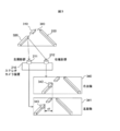
図1に示すように、実施の形態に係るダンプトラック(作業車両)10は、車体1と、車体1上に設置された運転室2及びベッセル3と、車体1に取り付けられた左右1対の駆動輪4と、これら1対の駆動輪4のそれぞれを駆動する1対の電動機4aを有している。ダンプトラック10は、自律走行する無人運転車両であっても良いし、運転室2内に備えられた図示しない運転装置をオペレータが操作して走行する有人運転車両であっても良い。車体1には、外界認識装置20が搭載される。なお、図中の符号5はダンプトラック10の前照灯を示し、符号6は運転室2内に備えられたモニタを示している。
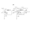
外界認識装置20は、図1に示すように、ステレオカメラ装置(3次元センサ)210と、距離情報算出部220と、走行路面検出部221と、路肩認識部222と、路肩判定部230と、地図データ240と、ロケータ250と、車両制御部270と、外部通信装置280を備えて構成される。
ステレオカメラ装置210は、少なくとも2つ(図1の例では、左右の2つ)のカメラを平行に配置したもので、各カメラの光軸をダンプトラック10の前進方向に向けて、車体1上に設置される。
距離情報算出部220は、ステレオカメラ装置210の左右のカメラで撮像されたダンプトラック10の前進方向の画像データを取得し、これらの画像データを3次元情報に変換して、撮像された立体物の距離情報を算出する。距離情報算出部220の機能については、後に図2~図5及び図7~図11を用いて説明する。
走行路面検出部221は、距離情報算出部221で得られた3次元情報から、ダンプトラック10が走行可能な走行路の路面部分を検出する。走行路面検出部221による路面の検出手順については、後に図6を用いて説明する。
路肩認識部222は、走行路面検出部221で検出された路面よりも所定の高さをもつ路端の立体物を路肩として認識する。鉱山においては、通常、走行路からのダンプトラック10の逸脱を防止するための逸脱防止ガードとして、土砂を盛り上げることにより形成される土壁が路肩に沿って設けられるので、本実施形態の路肩認識部222は、具体的には、土壁の有無、位置及び高さ等を認識する。以下の説明においては、逸脱防止ガードとして土壁を形成した場合を例にとって説明するが、土壁以外の立体物、例えばガイドレールや縁石を設置した場合についても同様の手順で認識される。
地図データ240は、鉱山に開削されたダンプトラック10の走行路に関する情報を電子データの形で編集したものであり、全ての走行路について、土壁に関する情報、例えば、土壁の形成区間及びその高さ寸法等が記載されている。また、地図データ240には、走行路に交差点がある場合、その交差点に関する情報、例えば、交差点の位置や交差する各走行路の路幅等についても記載される。
ロケータ250は、ダンプトラック10の現在位置と進行方向の方位を計測するものであり、本実施の形態においては、GPS2510と、ジャイロセンサ2520、加速度センサ2530をもって構成されている。GPS2510は、ダンプトラック10の位置を緯度経度情報で出力する。ジャイロセンサ2520は、ダンプトラック10の進行方向を示す方位を出力する。加速度センサ2530は、GPS2510の計測周期の間を補間した位置の推定や、GPS2510が衛星からの電波が受信不良になった場合の位置の推定などに用いる。
路肩判定部230は、路肩認識部222の認識結果と、ロケータ250が示すダンプトラック10の現在位置に相当する地図データ240上の位置に記載された土壁に関する情報を照合し、これらが一致しているか、不一致であるかを判定する。具体的な判定例については、後に図13を用いて説明する。路肩判定部230は、路肩認識部222の認識結果と地図データ240中に記載された土壁に関する情報とが不一致であると判定したときには、車両制御部270及び外部通信装置280に不一致信号を出力する。
車両制御部270は、路肩判定部230から不一致信号を受信したとき、所要の制御信号を生成し、これをダンプトラック10に備えられた車体1並びに車体1に搭載された図示しないエンジン及びモニタ6等の駆動を制御する。これにより、不一致の判定を行った鉱山車両(自車両)について、危険を回避するための所要の動作を行わせることができるので、ダンプトラック10の運行の安全性が高められる。なお、車両制御部270としては、車体5に搭載された車体コントローラ、エンジンコントローラ、表示コントローラ等を利用することもできる。
車両制御部270から鉱山車両を自動的に走行状態から停止状態に移行させる制御信号を出力した場合には、路肩判定部230の判定結果に基づいて自車両を自動的に停止させることができるので、自律走行する無人運転の鉱山車両について、安全走行を確保することができる。また、車両制御部270からモニタ6に路肩認識部222の判定結果を表示させる制御信号を出力した場合には、運転者に異常の発生を報知できるので、有人運転の鉱山車両について、安全走行を確保することができる。
外部通信装置280は、路肩判定部230から不一致信号が出力されたとき、不一致信号を含む所要のデータ信号を、鉱山で稼動する全ての鉱山車両の運行を管理する管理センタに送信する。これにより、鉱山内で稼動する他の鉱山車両が走行路の安全に関する情報を共有できるので、鉱山全体として、鉱山車両の安全管理を行うことができる。鉱山車両の管理システムに関しては、後に図19を用いて説明する。
次に、図1に示した距離情報算出部220における処理の内容を、図2~図5を用いて説明する。
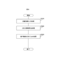
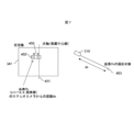
図2のフローチャートに示すように、距離情報算出部220においては、まずS100で、ステレオカメラ装置210にて撮像した画像データの入力処理を行う(手順)。次に、S110に進んで、S100で取得した左右2枚の画像を比較し、同一物体の対応点を算出して特定する。即ち、図3に示すように、走行路300の路肩に形成された3次元形状の土壁(逸脱防止ガード)320をステレオカメラ装置210で撮像すると、左右の撮像部211、212で撮像された画像は、それぞれ右画像340、左画像341のようになる。この図から明らかなように、ステレオカメラ装置210の各撮像部211、212で撮像された画像は、各撮像部211、212の設定位置が異なることから、土壁320上の一点に着目した場合、右画像340と左画像341とで異なる位置に撮像される。図3の例においては、土壁320上の特定の一点が、右画像340では符号342で示す位置に撮像され、左画像341では符号343で示す位置に撮像されていて、画像の横方向にd1のずれが生じている。従って、ステレオカメラ装置210から土壁320上の特定の一点までの距離を算出するためには、左画像341に符号343で示す位置に撮像されている土壁上の特定の一点が、右画像340のどの位置に撮像されているかを特定する必要がある。
この方法を図4で説明する。まず、図4に示すように、左画像341及び右画像340の座標系は、横方向をu軸352、縦方向をv軸351とする。そして、左画像341に (u1,v1)、(u1,v2)、(u2,v1)、(u2,v2)で囲まれた矩形領域355を設定する。次に、右画像340において、(U,v1)、(U,v2)、(U+(u2-u1),v1)、(U+(u2-u1),v2)で囲まれた矩形領域353を設定し、この矩形領域353のUの値をu=0から1ずつ増加して、矩形領域353を右画像340の右方向へ走査させる。走査させる際、矩形領域355内の画像と、矩形領域353内の画像の相関値を比較し、左画像341の矩形領域355と相関性が最も高い右画像340の矩形領域354の位置を抽出する。図4の例では、左画像341の矩形領域355と相関性が最も高い右画像340の矩形領域354の位置が、(u4,v1)、(u4,v2) 、(u4+(u2-u1),v1)、(u4+(u2-u1),v2)であるとする。これにより、矩形領域355内の各画素が対応する矩形領域354内の各画素を求めることができる。右画像340の矩形領域353を走査した結果、相関値がある一定以上の値になる矩形がない場合には、左画像341の矩形領域355に対応する右画像340内の対応点無しとする。
矩形領域355についての対応点の算出が終了した後は、左画像341の矩形領域を356の位置にずらし、同様の処理を行う。さらに、u方向についての操作が終了した後は、v方向に設定される矩形領域についても、同様の処理を行う。このようにして、左画像341の全画素に対して、右画像340内の対応点を求める。対応点が見つからない場合は、対応点無しとする。
左画像341の全画素に対する右画像340内の対応点の算出が終了した後は、図2のフローチャートに戻って、S120の距離算出処理を行う。S120では、S110で求めた左画像341と右画像340の対応点に関して、ステレオカメラ装置210からの距離を算出する。
以下に、図5を用いて、ステレオカメラ装置210から左画像341と右画像340の対応点までの距離の算出方法につき説明する。
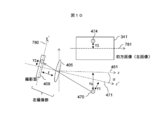
図5において、左撮像部211は、レンズ405と撮像面409が光軸403上に配置された焦点距離がfのカメラであり、右撮像部212は、レンズ404と撮像面408が光軸402上に配置された焦点距離がfのカメラである。各カメラの前方にある点401は、左撮像部211の撮像面409については点407(光軸403からd2の距離)へ撮像され、左画像341では点407(光軸403からd4画素の位置)となる。同様に、点401は、右撮像部212の撮像面408については点406(光軸402からd3の距離)に撮像され、右画像340では点406(光軸402からd5画素の位置)となる。
このように同一の物体上の点401が、左画像341では光軸403から左へd4画素の位置、右画像340では光軸402から右へd5の位置に撮像され、d4+d5画素の視差が発生する。このため、左の撮像部211の光軸403と点401との距離をxとすると、以下の式により、ステレオカメラ装置210から点401までの距離Dを求めることができる。
即ち、図5において、点401と左撮像部211の位置関係から、d2:f=x:Dが成り立ち、点401と右撮像部212の位置関係からd3:f=(d-x):Dが成り立つ。従って、D=f×d/(d2+d3)=f×d/ { (d4+d5 ) ×a} となる。ここで、aは撮像面409の撮像素子のサイズである。このようにして求められるステレオカメラ装置210から対応点までの距離算出を、S110で算出した全ての対応点について実施する。これにより、ステレオカメラ装置210から対象物までの距離を表現した距離画像を求めることができる。
図2のフローチャートの距離情報出力処理S130では、この距離画像を出力して保存する。
次いで、図2のフローチャートのS140に進み、左撮像部211及び右撮像部212から画像入力信号があるか否かを判定する。S140で左撮像部211及び右撮像部212からの画像入力信号がある(Yes)と判定した場合は、S100に戻る。S140で左撮像部211及び右撮像部212からの画像入力信号がない(No)と判定した場合は、画像入力信号が距離情報算出部220に入力されるまで待機する。
次に、図1に示した走行路面検出部221の動作を、図6のフローチャートを用いて説明する。
まず、S310において、距離情報算出部220から出力される距離画像の読み込み処理を行う。次に、S320に進んで、S310で読み込んだ距離画像を用いて、3次元情報算出処理を行い、画面上の各画素の3次元位置を求める。距離画像は、図7に示すように、左撮像部211で撮像した左画像341の各画素Pk(k=1~N、Nは左画像341の画素数)452を撮像している対象453のステレオカメラ装置210からの距離dkを、左画像341の全画素について算出したものである。この距離dkを用いて、撮像対象453の3次元座標値(xk,yk,zk)を計算する。ここで、3次元座標は、図8に示すように、ダンプトラック10を上から見て、車両の進行方向をz軸461、z軸461に垂直で車両の左右方向の軸をx軸460、z軸に垂直で車両の上下方向の軸をy軸とする。
図8に示した撮像対象453のx座標値xkは、以下の方法で算出できる。即ち、図9において、左撮像部211は、レンズ405と撮像面409が光軸であるz´軸471上に配置された焦点距離がfのカメラである。そして、図8のz軸461と図9のz´軸471は、図8のxz平面と垂直な平面と同じ平面上にあり、z軸461とz´軸471の成す角度は、ステレオカメラ装置210の設置俯角αと一致する。また、図9の撮像面409を含み、z´軸471に垂直な軸をx´軸472とすると、図9のx´軸472と図8のx軸460とが一致する。ここで、図8の撮像対象453を図9の点470としたとき、点470が撮像面409の光軸471からX2の位置に撮像されるとする。ここで、撮像面409における撮像素子サイズのx´軸472方向のサイズをaとすると、点470は、左画像341の光軸471からX=X2/aの画素の位置474に撮像される。また、点470のカメラからの距離をdkとすると、X2:f=X1:D1の関係が成り立つ。但し、D1=dk×cosθであり、θはtanθ=X2/fである。従って、X1=D1×X2/f=D1×X3×a/fとなる。ここで、X3は、図7に示した撮像対象453に相当する画素数になる。図7において、光軸位置に相当する画面中心線を451としたとき、対象としている画素Pk452の画面中心線451からの画素数がX3に相当する。また、X2が図8のxkと同じである。
図8に示した撮像対象453のy座標値ykは、以下の方法で算出できる。即ち、図10において、左撮像部211は、レンズ405と撮像面409が光軸であるz´軸471上に配置された焦点距離がfのカメラである。図10のz軸461は、図8のz軸461と同じであり、z軸461とz´軸471の成す角度は、ステレオカメラ装置210の設置俯角αと一致する。また、図10の撮像面409を含み、z´軸471に垂直な軸をy´軸780とする。また、図8の撮像対象453を図9の点470としたとき、点470が撮像面409の光軸471からY2の位置に撮像されるとする。ここで、撮像面409における撮像素子のy´軸780方向のサイズをbとすると、点470は、左画像341の画面中央781からY3=Y2/aの画素の位置474に撮像される。また、点470のカメラからの距離をdkとすると、
Yk=dk×sin(θ+α) (θは、tanθ=Y2/f)となる。
Yk=dk×sin(θ+α) (θは、tanθ=Y2/f)となる。
図8に示した撮像対象453のz座標値zkについても、同様の方法で算出でき、
zk=dk×cos(θ+α) (ここでθは、tanθ=Y2/f)
となる。
zk=dk×cos(θ+α) (ここでθは、tanθ=Y2/f)
となる。
以上の計算を図7に示した左画像341の全画素について行い、画素Pkの3次元座標(xk、yk、zk)を得る。
次に、図6のフローチャートのS330に戻って、走行路面式当てはめ処理を行う。走行路面式当てはめ処理S330では、前処理である3次元情報算出処理S320で求めた左画像341の各画素のうち、走行路面である可能性が高い画素を抽出する。図11に示す左画像341は、左の撮像部211で撮像した画像であり、走行路300が左撮像に撮像されている。また、図11に示す立体物310、320、330は、走行路300の路肩に沿って形成された土壁であり、ダンプトラック10の近傍で、土壁310、320、330を含まない部分602を、走行路面式当てはめに使用する画素として抽出する。
走行路面式は、図8に示す座標系において、ax+by+cz+d=0で表され、この走行路面式に、上記で抽出した画素の3次元座標Pi(xi,yi,zi)(但し、i=0~j、jは抽出した画素の個数)を当てはめて、Piを満たすパラメータa,b,cを算出することにより、走行路面を求めることができる。
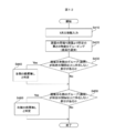
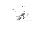
次に、図1に示した路肩認識部222の動作を、図12のフローチャートを用いて説明する。上述したように、本実施の形態では、走行路300の路肩に所定高さの土壁310、320、330が形成されている。従って、路面より所定の高さがある立体物を検出できれば路肩の土壁を検出できる。土壁の検出に際しては、まずS410で左画像341の各画素の3次元情報を入力する。これらの情報を用いて、路肩認識部222は、路面の両端で、路面より所定の高さの立体物をグルーピングする(S420)。例えば、図15にように、左画像341の各画素で路面300の両端で、路面300よりも所定の高さだけ高くなっている部分をグルーピングする。土壁3101、3102は、路面300より高さHの部分をグルーピングすることで抽出した部分であり、図15の例では距離Lだけ分離している。
次にS430で、路面の左側に存在する立体物のグループが所定の間隔以上に存在しない部分があるかどうかを判定する。もし存在しない部分が有れば、S440に進んで、左側に路肩無しと判定する。路面の右側についても、S450とS460で同様な判定を行う。
これだけでは、立体物のグループが所定の間隔以上に存在しない原因が、元々その部分に土壁が形成されていなかったのか、それとも崩落などにより土壁や路肩自体が外界認識装置20から見えなくなったのか、さらには他の鉱山車両等の陰になって見えない状態になっているのかを判定できない。そこで、地図データ240を参照して、立体物の検出位置に土壁に関する情報が書き込まれているのかを路肩判定部230で判定する。
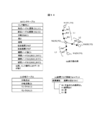
地図データ240は、ダンプトラック10の走行路300をリンクとノードで示すものであり、図14に示すデータフォーマットとなっている。(a)は走行路の例を示したもので、ノードN1とN2間のリンクL1、ノードN2とN3間のリンクL2、ノードN2とN4間のリンクL3があると仮定し、ノードN1からN4に向けてダンプトラック10が走行するものとする。また、その途中のノードN2で分岐路L2が存在する。各ノード間には走行路の形状を折れ線で近似するために補間ノードが定義される。例えばノードN1とノードN2の間には、補間ノードIN1,IN2,IN3が定義され、ノードN2とノードN4の間には、補間ノードIN6,IN7が定義され、ノードN2とノードN3の間には、補間ノードIN4,IN5が定義される。これらの情報は(b)のリンクテーブルと(c)の分岐テーブルで定義される。(b)のリンクテーブルは、リンク番号L1に対して、始点ノードN1と終点ノードN2の位置を示すための緯度経度からなる座標値、分岐点の情報を示す分岐点ID、リンクL1の実際の長さと道路幅、走行路の左右に路肩が存在するかどうかのフラグ、補間点の数を示す補間ノード数とそれぞれの補間点の緯度経度座標からなる。左右路肩フラグは(d)に示すフォーマットになっており、路肩属性の2ビットが00の場合は、走行路よりも十分に広い平面の場所に走行路があるため路肩が不要な場所であり路肩なしを示す。路肩属性が01の場合は、土盛りされた路肩が存在し、その場合は、路肩の高さ(RH)で路肩の高さが定義される。路肩属性が10の場合は、路肩に沿って土壁が存在する。路肩属性が11の場合は、路面の端が崖になっていて、路面より高い構造物が存在しないことを示す。
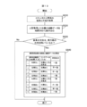
図13に、路肩判定部230の処理フローを示す。まずS510でロケータ250からダンプトラック10の位置情報と進行方位を取得する。S520では、上記取得した位置情報に基づき、地図データ240からダンプトラック10が現在走行中の道路のリンクデータを読み出す。S530では、ダンプトラック10の進行方向と、S520で読み出したリンク情報の向きを照合し、方向が一致しているかどうかを判定する。仮に所定の誤差以上に方位がずれている場合には、路肩判定の処理は行わない。例えば、ダンプトラック10が路上の障害物(図示しない)を避けるために、路上でダンプトラック10の向きを変えた場合等がこれに該当する。
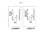
その後、S540に移行し、地図データ240から読み出したリンクデータの路肩フラグの情報と路肩認識部222の判定結果とを照合して、それらの各情報が一致しているのか、不一致であるのかの判定を行う。例えばS540のNo.1では路肩認識部222の認識結果が「路面左側に土壁なし」であり、リンクデータの左側路肩フラグに「土壁無し」と記載されているか、地図データ240が交差点(分岐ノード)となっている場合には、路肩認識部222が土壁を認識できなくても、路肩認識部222の判定結果に異常はないので、「一致」を示す判定結果を出力する。例えば、図16の(b)に示すように、分岐路によって路肩が途切れている場合が該当する。これに対して、S540のNo.2のように、路肩認識部222が土壁を認識できない場合であって、左側路肩フラグが「土壁あり」となっている場合には、実際には路肩に沿って土壁が存在するにも拘らず、路肩認識部222が土壁を見失っているということであるので、「不一致」を示す判定結果を出力する。例えば図16の(a)のように路肩が崩落している場合や、図17のように走行路300の端に停車している車両700などの障害物で路肩が見えなくなっている場合がこれに該当する。これとは逆に、S540のNo.3のように、路肩認識部222が土壁を認識したにも関わらず、左側路肩フラグが「土壁無し」となっている場合は「不一致」と判定する。これにより、地図データ240の記載ミスや、地図データが古い可能性があることを判定できる。また、S540のNo.4のように、路肩認識部22が土壁を認識しており、かつ地図データの左側路肩フラグが「土壁あり」となっている場合は、両者が一致しているので、「一致」と判定する。走行路300の右側についても、これと同様に判定する。
路肩判定部230は、路肩認識部222の認識結果と地図データ240に書き込まれた土壁に関する情報とが不一致であると判定した場合、不一致信号を車両制御部270及び外部通信装置280に送信する。
車両制御部270は、路肩判定部230から不一致信号を受信したとき、自車両の危険を回避するため、車載機器の駆動を制御する制御信号を出力し、例えばダンプトラック10を自動的に停止させたり、運転室2に備えられたモニタ6に路肩判定部230から不一致信号が出力されたことを示す警告を表示する。なお、モニタ6への警告の表示に加えて、光や音による警報を発することもできる。制御信号として、自車両を自動的に走行状態から停止状態に移行させる信号を出力すると、路肩判定部230の判定結果に基づいて自車両を自動的に停止させることができるので、自律走行する無人運転の鉱山車両について、安全走行を確保することができる。また、制御信号として、自車両の運転席2に備えられたモニタ6に路肩認識部の判定結果に基づく警報を表示させる信号を出力すると、運転者に異常の発生を報知できるので、有人運転の鉱山車両について、安全走行を確保することができる。
なお、上述の実施形態においては、外界認識装置20にステレオカメラ装置210を備えたが、かかる構成に代えて、図18に示すように、外界認識装置20に3次元レーザスキャナ710を備えることもできる。3次元レーザスキャナ710は、レーザ光線を周囲に放出し、その反射時間を計測することで周囲の物体の3次元情報を計測する。従って、3次元レーザスキャナ710を用いる場合には、図6の処理フローのうち、3次元情報算出処理S320を省略でき、その後の走行路面式当てはめ処理S330から行えば良い。
外部通信装置280は、路肩判定部230から不一致信号を受信したとき、図19に示すように、鉱山の管理センタ31に備えられたコントロールシステム30に、路肩認識部222の認識結果と、地図データ240に書き込まれた土壁に関する情報と、これらの各情報が不一致である旨の通報を行う。管理センタ31は、鉱山全体の管理を行う部署であり、コントロールシステム30は、鉱山で稼動している各ダンプトラック10、11からの通報の受信と、各鉱山車両10、11への指令信号の送信、各鉱山車両10、11についての走行ルート作成、及び走行路300の路面や路肩のメンテナンス計画等を行う。なお、図19において、符号310、320、330は、走行路300の路肩に沿って形成された土壁を示している。
コントロールシステム30は、1のダンプトラック10から、路肩認識部222の認識結果と地図データ240に書き込まれた土壁に関する情報とが不一致である旨の通報を受けたとき、所要の指令信号を作成し、鉱山で稼動している他のダンプトラック11に送信する。指令信号としては、例えば通報を行った1のダンプトラック10(自車両)に後続する他の鉱山車両(後続車両)11を停止させるための停止指令信号、後続車両11に備えられたモニタ6に所要の警報データを表示させるためのモニタ駆動信号、路肩補修用の作業車両に作業依頼を行う路肩補修指令信号、それに地図データ240の更新を指令する地図データ更新指令信号などがある。指令信号として、停止指令信号を出力すると、後続車両11を自動的に走行状態から停止状態に移行させることができるので、自律走行する無人運転の鉱山車両について、安全走行を確保することができる。また、前記指令信号として、モニタ駆動信号を出力すると、後続車両11の運転者に異常の発生を報知できるので、有人運転の鉱山車両について、安全走行を確保することができる。
なお、1のダンプトラック10が路肩を正常に認識できなかった場合においても、走行上、その影響を直接的に受けるのは、当該1の鉱山車両と、それに後続する1又は複数台の鉱山車両であって、必ずしも鉱山内で稼動する全ての鉱山車両に影響が及ぶわけではない。したがって、コントロールシステム30は、必ずしも鉱山で稼動している全てのダンプトラックに指令信号を送信する必要はなく、一部の後続車両11にのみ送信することもできる。この場合、コントロールシステム30は、指令信号を送信すべき範囲(例えば自車両10からの距離)を予め記憶しておき、自車両10から不一致信号が送信されたとき、これに後続する車両のうちの、予め記憶された範囲内を走行中の後続車両にのみ、指令信号を送信することもできる。これにより、必要な範囲でダンプトラック10、11の安全を確保することができる。
以下、本発明に係る鉱山車両及び鉱山車両管理システムの他の実施形態について説明する。この他の実施形態に係る鉱山車両及び鉱山車両管理システムは、走行路300の路肩に沿って形成される土壁310、320、330の高さ判定処理を行って、土壁310、320、330が所定の高さに維持されているか、崩落状態にあるかの判断を更に行うことを特徴とする。
本例の鉱山車両及び鉱山車両管理システムは、路肩判定部230において、図20及び図21に示す処理フローを実行する。即ち、ダンプトラック10の路肩判定部230は、図20のS510~S541に示す手順で、路肩認識部222の認識結果と地図データ240に書き込まれた土壁310、320、330に関する情報との一致・不一致を判定すると共に、土壁310、320、330の高さ判定を行うか否かの判定を行う。S510~S530の処理は、先に図13を用いて説明した通りであるので、重複を避けるために説明を省略する。また、S541の判定処理のうち、路肩認識部222の認識結果と地図データ240に書き込まれた土壁310、320、330に関する情報との一致・不一致を判定する処理についても、先に図13を用いて説明した通りであるので、重複を避けるために説明を省略する。S541においては、先に図13を用いて説明した処理に加え、路肩認識部222が走行路300の左側に土壁310、320があると認識すると共に、地図データ240の該当する部分に土壁310、320に関する情報が書き込まれている場合には、「高さ判定」の判定結果を出力する。また、路肩認識部222が走行路300の右側に土壁330があると認識すると共に、地図データ240の該当する部分に土壁330に関する情報が書き込まれている場合も同様である。
路肩判定部230は、S541の判定結果に基づいて、S542で土壁310、320、330の高さ判定が必要であるか否かを判定し、必要と判定した場合には、S543に移行して、土壁310、320、330の高さ判定処理を実行する。
土壁310、320、330の高さ判定処理は、図21に示す手順で行われる。まず、S610で、路肩判定部230は、路肩認識部222から土壁310、320、330の高さHを取得する。高さHは、図15に示すように、路面から土壁310、320、330の頂面までの距離である。次に、S620に進んで、土壁の高さHがこの計測誤差範囲になっているかどうかを判定する。即ち、土壁の高さ計測には、誤差が発生し得るので、土壁に全く異常が無い状態でも、地図データに記載された土壁の高さデータRHと同一にならない場合が有る。そこで、地図データに記載された土壁の高さデータRHと計測された土壁の高さHとの差(RH-H)が閾値S1の範囲内にあるか否かを判定する。閾値S1は、土壁310、320、330の形成時に許容される高低差の許容値に基づいて設定され、路肩判定部230に記憶される。S620で土壁の高さHが誤差範囲内にあると判定した場合は、S650に移行し、土壁の高さが正常である旨を、外部通信装置280を通して管理センタ31のコントロールシステム30に送信する。
S620で土壁の高さHが計測誤差範囲にないと判定した場合は、S630に進んで、土壁の一部に崩落が発生しているか否かについて判定する。具体的には、地図データに記載された土壁の高さデータRHと計測された土壁の高さHとの差(RH-H)が閾値S2の範囲内にあるか否かを判定する。閾値S2は、ダンプトラック10の安全な通行が困難になる土壁310、320、330の高さに基づいて設定され、路肩判定部230に記憶される。S630で(RH-H)が閾値S2よりも大きいと判定した場合は、S640に進んで、土壁310、320、330に崩落の可能性がある旨を、外部通信装置280を通して管理センタ31のコントロールシステム30に送信する。S630で(RH-H)が閾値S2よりも小さいと判定した場合は、S660に進んで、土壁310、320、330の補修が必要である旨を、外部通信装置280を通して管理センタ31のコントロールシステム30に送信する。
このように、本実施形態においては、2段階の閾値S1、S2を設定したので、土壁310、320、330の状態を正確に判定することができ、鉱山車両のより一層の安全確保が図れると共に、路肩の補修や地図データ240の更新を円滑に行うことができる。
なお、本発明は、上述した実施の形態に限定されるものではなく、要旨を変更しない範囲で適宜変形して実施することができる。例えば、上述した実施の形態では、鉱山車両としてダンプトラックを例にとって説明したが、その他、油圧ショベル、ホイールローダ、散水車、パトロールカーなど、鉱山で運用される全ての車両について適用することができる。また、上述した実施の形態では、走行路300からの鉱山車両の逸脱を防止するための逸脱防止ガードとして、走行路300の路肩に沿って土壁を形成した場合を例にとって説明したが、土壁に代えて、ガードレールや置き石などを走行路300の路肩に沿って設置した場合にも同様に適用できる。
1 車体
2 運転席
3 ベッセル
4 駆動輪
4a 電動機
5 前照灯
6 モニタ
10 車両
20 外界認識装置
210 ステレオカメラ装置
220 距離情報算出部
221 走行路面検出部
222 路肩認識部
230 路肩判定部
240 地図データ
250 ロケータ
270 車両制御部
280 外部通信装置
300 走行路
310、320、330 土壁
710 3次元レーザスキャナ
2 運転席
3 ベッセル
4 駆動輪
4a 電動機
5 前照灯
6 モニタ
10 車両
20 外界認識装置
210 ステレオカメラ装置
220 距離情報算出部
221 走行路面検出部
222 路肩認識部
230 路肩判定部
240 地図データ
250 ロケータ
270 車両制御部
280 外部通信装置
300 走行路
310、320、330 土壁
710 3次元レーザスキャナ
Claims (9)
- 車体に取り付けられた左右1対の駆動輪と、
これら1対の駆動輪のそれぞれを駆動する1対の電動機と、
これら1対の電動機の駆動及び停止を制御する車両制御部と、
前記車体の周囲を3次元計測する3次元センサと、
前記3次元センサからの情報を用いて、走行路及び当該走行路の路肩に沿って形成された逸脱防止ガードを認識する路肩認識部と、
前記車体の現在位置と方位を計測するロケータと、
前記走行路に関する情報及び前記逸脱防止ガードに関する情報を有する地図データと、
前記ロケータが示す位置における前記地図データの情報と前記路肩認識部の認識結果とを照合して、それらが一致しているか否かの判定を行い、不一致と判定したときに不一致信号を出力する路肩判定部と、
を備えたことを特徴とする鉱山車両。 - 請求項1に記載の鉱山車両において、
前記車両制御部は、前記路肩判定部からの前記不一致信号の出力を受けて鉱山車両の制御信号を生成し、当該制御信号により鉱山車両を自動的に走行状態から停止状態に移行させることを特徴とする鉱山車両。 - 請求項1に記載の鉱山車両において、
前記車両制御部は、前記路肩判定部からの前記不一致信号の出力を受けて鉱山車両の運転席に備えられたモニタの制御信号を生成し、当該制御信号により前記モニタに前記路肩認識部の判定結果を表示させることを特徴とする鉱山車両。 - 請求項1に記載の鉱山車両において、
前記不一致信号を外部に送信する通信装置を更に備えたことを特徴とする鉱山車両。 - 請求項1に記載の鉱山車両において、
前記地図データは、交差点に関する情報を含んで構成され、前記路肩判定部は、前記ロケータが示す位置に相当する前記地図データ上の位置に交差点が示され、かつ当該位置において前記路肩認識部が前記逸脱防止ガードを認識しない場合には、前記地図データの情報と前記路肩認識部の認識結果は一致と判定することを特徴とする鉱山車両。 - 請求項1に記載の鉱山車両において、
前記路肩判定部は、前記走行路の路肩に沿って形成された逸脱防止ガードの高さに関する閾値を予め記憶しており、前記路肩認識部が取得した前記逸脱防止ガードの高さ情報と前記閾値とに基づいて、前記路肩認識部が取得した前記逸脱防止ガードの高さが正常であるか否かを判定することを特徴とする鉱山車両。 - 請求項6に記載の鉱山車両において、
前記路肩判定部は、前記路肩認識部が取得した前記逸脱防止ガードの高さ情報と前記閾値とに基づいて、路肩の補修が必要か否かの判定を更に行うことを特徴とする鉱山車両。 - 走行路を走行する複数の鉱山車両と、コントロールシステムを用いて前記複数の鉱山車両の運行を一元的に管理する管理センタとから構成され、
前記鉱山車両は、車体の周囲を3次元計測する3次元センサと、前記3次元センサからの情報を用いて、走行路及び当該走行路の路肩に沿って形成された逸脱防止ガードを認識する路肩認識部と、前記車体の現在位置と方位を計測するロケータと、前記走行路に関する情報及び前記逸脱防止ガードに関する情報を有する地図データと、前記ロケータが示す位置における前記地図データの情報と前記路肩認識部の認識結果とを照合して、それらが一致しているか否かの判定を行い、不一致と判定したときに不一致信号を出力する路肩判定部と、前記不一致信号を外部に送信する通信装置とを備え、
前記管理センタのコントロールシステムは、前記通信装置からの不一致信号を受信したとき、前記走行路を走行中の他の鉱山車両に対して、当該他の鉱山車両を自動的に走行状態から停止状態に移行させる指令信号を出力するか、当該他の鉱山車両の運転席に備えられたモニタに前記不一致信号を表示させる指令信号を送信することを特徴とする鉱山車両の管理システム。 - 請求項8に記載の鉱山車両の管理システムにおいて、
前記管理センタのコントロールシステムは、前記指令信号を送信すべき範囲を予め記憶しており、1の鉱山車両から前記不一致信号が送信されたとき、当該1の鉱山車両に後続する他の鉱山車両であって、前記指令信号を送信すべき範囲内に存在する鉱山車両に前記指令信号を選択的に送信することを特徴とする鉱山車両の管理システム。
Applications Claiming Priority (2)
| Application Number | Priority Date | Filing Date | Title |
|---|---|---|---|
| JP2013172505A JP6175309B2 (ja) | 2013-08-22 | 2013-08-22 | 鉱山車両 |
| JP2013-172505 | 2013-08-22 |
Publications (1)
| Publication Number | Publication Date |
|---|---|
| WO2015025587A1 true WO2015025587A1 (ja) | 2015-02-26 |
Family
ID=52483372
Family Applications (1)
| Application Number | Title | Priority Date | Filing Date |
|---|---|---|---|
| PCT/JP2014/065115 Ceased WO2015025587A1 (ja) | 2013-08-22 | 2014-06-06 | 鉱山車両及び鉱山車両の管理システム |
Country Status (2)
| Country | Link |
|---|---|
| JP (1) | JP6175309B2 (ja) |
| WO (1) | WO2015025587A1 (ja) |
Cited By (4)
| Publication number | Priority date | Publication date | Assignee | Title |
|---|---|---|---|---|
| CN113671895A (zh) * | 2021-08-23 | 2021-11-19 | 北京北矿智能科技有限公司 | 一种矿山井下溜井自适应放矿系统 |
| CN113758495A (zh) * | 2021-09-10 | 2021-12-07 | 上海伯镭智能科技有限公司 | 一种基于矿山无人驾驶的寻路方法 |
| CN114706380A (zh) * | 2022-02-16 | 2022-07-05 | 南京司凯奇汽车科技有限公司 | 一种矿山无人驾驶机车控制装置及控制方法 |
| CN117560473A (zh) * | 2024-01-12 | 2024-02-13 | 北京瞭望神州科技有限公司 | 基于自然资源矿山监管场景视频数据处理方法及装置 |
Families Citing this family (3)
| Publication number | Priority date | Publication date | Assignee | Title |
|---|---|---|---|---|
| JP6485280B2 (ja) * | 2015-08-10 | 2019-03-20 | 日産自動車株式会社 | 段差検出装置及び段差検出方法 |
| CN121734450A (zh) | 2020-07-08 | 2026-03-27 | 株式会社电装 | 自动驾驶装置、车辆控制方法 |
| JP7688989B2 (ja) * | 2021-03-09 | 2025-06-05 | パイオニア株式会社 | 情報処理装置、制御方法、プログラム及び記憶媒体 |
Citations (4)
| Publication number | Priority date | Publication date | Assignee | Title |
|---|---|---|---|---|
| JPH09231500A (ja) * | 1996-02-21 | 1997-09-05 | Komatsu Ltd | 無人車両と有人車両混走時のフリート制御装置及び制御方法 |
| JP2007272647A (ja) * | 2006-03-31 | 2007-10-18 | Denso Corp | 携帯用電子機器及び車載用電子機器 |
| JP2011215474A (ja) * | 2010-04-01 | 2011-10-27 | Toyota Motor Corp | 道路情報取得装置 |
| JP2012196999A (ja) * | 2011-03-18 | 2012-10-18 | Toyota Motor Corp | 車両用照明装置及び方法 |
-
2013
- 2013-08-22 JP JP2013172505A patent/JP6175309B2/ja not_active Expired - Fee Related
-
2014
- 2014-06-06 WO PCT/JP2014/065115 patent/WO2015025587A1/ja not_active Ceased
Patent Citations (4)
| Publication number | Priority date | Publication date | Assignee | Title |
|---|---|---|---|---|
| JPH09231500A (ja) * | 1996-02-21 | 1997-09-05 | Komatsu Ltd | 無人車両と有人車両混走時のフリート制御装置及び制御方法 |
| JP2007272647A (ja) * | 2006-03-31 | 2007-10-18 | Denso Corp | 携帯用電子機器及び車載用電子機器 |
| JP2011215474A (ja) * | 2010-04-01 | 2011-10-27 | Toyota Motor Corp | 道路情報取得装置 |
| JP2012196999A (ja) * | 2011-03-18 | 2012-10-18 | Toyota Motor Corp | 車両用照明装置及び方法 |
Cited By (6)
| Publication number | Priority date | Publication date | Assignee | Title |
|---|---|---|---|---|
| CN113671895A (zh) * | 2021-08-23 | 2021-11-19 | 北京北矿智能科技有限公司 | 一种矿山井下溜井自适应放矿系统 |
| CN113758495A (zh) * | 2021-09-10 | 2021-12-07 | 上海伯镭智能科技有限公司 | 一种基于矿山无人驾驶的寻路方法 |
| CN113758495B (zh) * | 2021-09-10 | 2023-11-14 | 上海伯镭智能科技有限公司 | 一种基于矿山无人驾驶的寻路方法 |
| CN114706380A (zh) * | 2022-02-16 | 2022-07-05 | 南京司凯奇汽车科技有限公司 | 一种矿山无人驾驶机车控制装置及控制方法 |
| CN117560473A (zh) * | 2024-01-12 | 2024-02-13 | 北京瞭望神州科技有限公司 | 基于自然资源矿山监管场景视频数据处理方法及装置 |
| CN117560473B (zh) * | 2024-01-12 | 2024-03-19 | 北京瞭望神州科技有限公司 | 基于自然资源矿山监管场景视频数据处理方法及装置 |
Also Published As
| Publication number | Publication date |
|---|---|
| JP2015041283A (ja) | 2015-03-02 |
| JP6175309B2 (ja) | 2017-08-02 |
Similar Documents
| Publication | Publication Date | Title |
|---|---|---|
| JP6175309B2 (ja) | 鉱山車両 | |
| CN112750333B (zh) | 异常判定装置、车辆辅助系统、服务器 | |
| KR102733277B1 (ko) | 저비용 자율 주행 셔틀 운행 방법 및 장치 | |
| JP6280850B2 (ja) | 障害物回避システム | |
| CN108995649B (zh) | 车辆的行驶控制装置 | |
| JP6385745B2 (ja) | 鉱山用作業車両 | |
| JP6438516B2 (ja) | 車両の走行制御装置 | |
| JP5997797B2 (ja) | 車両の地図データ処理装置 | |
| JP7324020B2 (ja) | 交通制御システム | |
| JP6564424B2 (ja) | 車両制御装置 | |
| US20150073705A1 (en) | Vehicle environment recognition apparatus | |
| KR20200029050A (ko) | 운전 지원 차량의 주행 제어 방법 및 주행 제어 장치 | |
| WO2016170855A1 (ja) | 車両及び鉱山用運搬車両の運用システム | |
| KR102000395B1 (ko) | 자율주행 차량의 운행 모드 전환을 위한 장치, 이를 위한 방법 및 이 방법을 수행하는 프로그램이 기록된 컴퓨터 판독 가능한 기록매체 | |
| US12198445B2 (en) | Drive assist device, drive assist method, and program | |
| KR102697526B1 (ko) | 주행경로 생성장치 및 제어장치 | |
| JP2009096361A (ja) | 車両走行支援装置 | |
| WO2018225347A1 (ja) | 走行障害検出装置及び車両ナビゲーションシステム | |
| JP3666332B2 (ja) | 歩行者検知装置 | |
| US20220001876A1 (en) | Drive planning device, storage medium storing computer program for drive planning and drive planning method | |
| JP7165012B2 (ja) | 車両用ステレオカメラ装置 | |
| WO2015163028A1 (ja) | 鉱山用作業車両用の路面推定装置および路面推定システム | |
| WO2020045426A1 (ja) | 車載機 | |
| KR102725597B1 (ko) | 무인 항공기와 통신하는 차량용 인포테인먼트 시스템 및 그 작동 방법 | |
| JP2022103505A (ja) | 車両制御装置、車両制御方法、およびプログラム |
Legal Events
| Date | Code | Title | Description |
|---|---|---|---|
| 121 | Ep: the epo has been informed by wipo that ep was designated in this application |
Ref document number: 14837989 Country of ref document: EP Kind code of ref document: A1 |
|
| NENP | Non-entry into the national phase |
Ref country code: DE |
|
| 122 | Ep: pct application non-entry in european phase |
Ref document number: 14837989 Country of ref document: EP Kind code of ref document: A1 |