WO2015025449A1 - 多段圧縮機及び冷凍サイクル装置 - Google Patents
多段圧縮機及び冷凍サイクル装置 Download PDFInfo
- Publication number
- WO2015025449A1 WO2015025449A1 PCT/JP2014/003432 JP2014003432W WO2015025449A1 WO 2015025449 A1 WO2015025449 A1 WO 2015025449A1 JP 2014003432 W JP2014003432 W JP 2014003432W WO 2015025449 A1 WO2015025449 A1 WO 2015025449A1
- Authority
- WO
- WIPO (PCT)
- Prior art keywords
- compression element
- stage compression
- partition plate
- intermediate pressure
- low
- Prior art date
- Legal status (The legal status is an assumption and is not a legal conclusion. Google has not performed a legal analysis and makes no representation as to the accuracy of the status listed.)
- Ceased
Links
Images

Classifications
-
- F—MECHANICAL ENGINEERING; LIGHTING; HEATING; WEAPONS; BLASTING
- F04—POSITIVE - DISPLACEMENT MACHINES FOR LIQUIDS; PUMPS FOR LIQUIDS OR ELASTIC FLUIDS
- F04C—ROTARY-PISTON, OR OSCILLATING-PISTON, POSITIVE-DISPLACEMENT MACHINES FOR LIQUIDS; ROTARY-PISTON, OR OSCILLATING-PISTON, POSITIVE-DISPLACEMENT PUMPS
- F04C18/00—Rotary-piston pumps specially adapted for elastic fluids
- F04C18/30—Rotary-piston pumps specially adapted for elastic fluids having the characteristics covered by two or more of groups F04C18/02, F04C18/08, F04C18/22, F04C18/24, F04C18/48, or having the characteristics covered by one of these groups together with some other type of movement between co-operating members
- F04C18/34—Rotary-piston pumps specially adapted for elastic fluids having the characteristics covered by two or more of groups F04C18/02, F04C18/08, F04C18/22, F04C18/24, F04C18/48, or having the characteristics covered by one of these groups together with some other type of movement between co-operating members having the movement defined in group F04C18/08 or F04C18/22 and relative reciprocation between the co-operating members
- F04C18/356—Rotary-piston pumps specially adapted for elastic fluids having the characteristics covered by two or more of groups F04C18/02, F04C18/08, F04C18/22, F04C18/24, F04C18/48, or having the characteristics covered by one of these groups together with some other type of movement between co-operating members having the movement defined in group F04C18/08 or F04C18/22 and relative reciprocation between the co-operating members with vanes reciprocating with respect to the outer member
- F04C18/3562—Rotary-piston pumps specially adapted for elastic fluids having the characteristics covered by two or more of groups F04C18/02, F04C18/08, F04C18/22, F04C18/24, F04C18/48, or having the characteristics covered by one of these groups together with some other type of movement between co-operating members having the movement defined in group F04C18/08 or F04C18/22 and relative reciprocation between the co-operating members with vanes reciprocating with respect to the outer member the inner and outer member being in contact along one line or continuous surfaces substantially parallel to the axis of rotation
- F04C18/3564—Rotary-piston pumps specially adapted for elastic fluids having the characteristics covered by two or more of groups F04C18/02, F04C18/08, F04C18/22, F04C18/24, F04C18/48, or having the characteristics covered by one of these groups together with some other type of movement between co-operating members having the movement defined in group F04C18/08 or F04C18/22 and relative reciprocation between the co-operating members with vanes reciprocating with respect to the outer member the inner and outer member being in contact along one line or continuous surfaces substantially parallel to the axis of rotation the surfaces of the inner and outer member, forming the working space, being surfaces of revolution
-
- F—MECHANICAL ENGINEERING; LIGHTING; HEATING; WEAPONS; BLASTING
- F01—MACHINES OR ENGINES IN GENERAL; ENGINE PLANTS IN GENERAL; STEAM ENGINES
- F01C—ROTARY-PISTON OR OSCILLATING-PISTON MACHINES OR ENGINES
- F01C21/00—Component parts, details or accessories not provided for in groups F01C1/00 - F01C20/00
- F01C21/10—Outer members for co-operation with rotary pistons; Casings
- F01C21/104—Stators; Members defining the outer boundaries of the working chamber
- F01C21/108—Stators; Members defining the outer boundaries of the working chamber with an axial surface, e.g. side plates
-
- F—MECHANICAL ENGINEERING; LIGHTING; HEATING; WEAPONS; BLASTING
- F04—POSITIVE - DISPLACEMENT MACHINES FOR LIQUIDS; PUMPS FOR LIQUIDS OR ELASTIC FLUIDS
- F04C—ROTARY-PISTON, OR OSCILLATING-PISTON, POSITIVE-DISPLACEMENT MACHINES FOR LIQUIDS; ROTARY-PISTON, OR OSCILLATING-PISTON, POSITIVE-DISPLACEMENT PUMPS
- F04C23/00—Combinations of two or more pumps, each being of rotary-piston or oscillating-piston type, specially adapted for elastic fluids; Pumping installations specially adapted for elastic fluids; Multi-stage pumps specially adapted for elastic fluids
- F04C23/001—Combinations of two or more pumps, each being of rotary-piston or oscillating-piston type, specially adapted for elastic fluids; Pumping installations specially adapted for elastic fluids; Multi-stage pumps specially adapted for elastic fluids of similar working principle
-
- F—MECHANICAL ENGINEERING; LIGHTING; HEATING; WEAPONS; BLASTING
- F04—POSITIVE - DISPLACEMENT MACHINES FOR LIQUIDS; PUMPS FOR LIQUIDS OR ELASTIC FLUIDS
- F04C—ROTARY-PISTON, OR OSCILLATING-PISTON, POSITIVE-DISPLACEMENT MACHINES FOR LIQUIDS; ROTARY-PISTON, OR OSCILLATING-PISTON, POSITIVE-DISPLACEMENT PUMPS
- F04C23/00—Combinations of two or more pumps, each being of rotary-piston or oscillating-piston type, specially adapted for elastic fluids; Pumping installations specially adapted for elastic fluids; Multi-stage pumps specially adapted for elastic fluids
- F04C23/008—Hermetic pumps
-
- F—MECHANICAL ENGINEERING; LIGHTING; HEATING; WEAPONS; BLASTING
- F04—POSITIVE - DISPLACEMENT MACHINES FOR LIQUIDS; PUMPS FOR LIQUIDS OR ELASTIC FLUIDS
- F04C—ROTARY-PISTON, OR OSCILLATING-PISTON, POSITIVE-DISPLACEMENT MACHINES FOR LIQUIDS; ROTARY-PISTON, OR OSCILLATING-PISTON, POSITIVE-DISPLACEMENT PUMPS
- F04C29/00—Component parts, details or accessories of pumps or pumping installations, not provided for in groups F04C18/00 - F04C28/00
- F04C29/12—Arrangements for admission or discharge of the working fluid, e.g. constructional features of the inlet or outlet
-
- F—MECHANICAL ENGINEERING; LIGHTING; HEATING; WEAPONS; BLASTING
- F04—POSITIVE - DISPLACEMENT MACHINES FOR LIQUIDS; PUMPS FOR LIQUIDS OR ELASTIC FLUIDS
- F04C—ROTARY-PISTON, OR OSCILLATING-PISTON, POSITIVE-DISPLACEMENT MACHINES FOR LIQUIDS; ROTARY-PISTON, OR OSCILLATING-PISTON, POSITIVE-DISPLACEMENT PUMPS
- F04C2240/00—Components
- F04C2240/80—Other components
- F04C2240/804—Accumulators for refrigerant circuits
Definitions
- Embodiments of the present invention relate to a multistage compressor and a refrigeration cycle apparatus.
- a low-stage compression element, a high-stage compression element, and a partition plate that partitions these compression elements are housed in a sealed case, and a low-pressure gas refrigerant as a working fluid is supplied to the low-stage compression element and compressed to an intermediate pressure.
- a multistage compressor in which a gas refrigerant compressed to an intermediate pressure is supplied to a high-stage compression element and compressed into a high-pressure gas refrigerant is known, and is described in, for example, Patent Document 1 below.
- the piping position of the two pipes is restricted to prevent interference between the pipe that supplies the low-pressure gas refrigerant to the low-stage compression element and the pipe that connects the low-stage compression element and the high-stage compression element. There is a problem.
- An object of an embodiment of the present invention is to supply an intermediate-pressure gas refrigerant compressed by a low-stage compression element to a high-stage compression element without using a pipe, and when working fluid is sucked into the high-stage compression element.
- an electric motor unit and a compression mechanism unit driven by a rotary shaft connected to the electric motor unit are accommodated in a sealed case, and the compression mechanism unit compresses a low-pressure working fluid to an intermediate pressure.
- the partition plate is formed by connecting a plurality of divided partition plates in the axial direction of the rotating shaft, and the intermediate-pressure working fluid compressed by the low-stage compression element inside the partition plate An intermediate pressure space in the partition plate is formed, and a suction port is formed on the end face of the partition plate facing the high-stage compression element to allow the working fluid in the intermediate pressure space in the partition plate to be sucked into the high-stage compression element. It is characterized by that.
- the refrigeration cycle apparatus of the embodiment includes the above-described multistage compressor, a condenser connected to the multistage compressor, an expansion device connected to the condenser, the expansion device, and the multistage compressor. And an evaporator connected between them.
- the intermediate-pressure gas refrigerant compressed by the low-stage compression element can be supplied to the high-stage compression element without using a pipe, and the suction loss when the working fluid is sucked into the high-stage compression element is reduced.
- a multistage compressor that can be reduced in size and a refrigeration cycle apparatus including the multistage compressor can be obtained.
- a refrigeration cycle apparatus 1 shown in FIG. 1 includes a compressor body 2 and a first accumulator 3, a multistage compressor 4 that compresses a gas refrigerant that is a working fluid, and a compressor body that is connected to the compressor body 2. 2, a condenser 5 that condenses the high-pressure gas refrigerant discharged from 2 to form a liquid refrigerant, an expansion device 6 that is connected to the condenser 5 and depressurizes the liquid refrigerant, and between the expansion device 6 and the first accumulator 3. And an evaporator 7 for evaporating the liquid refrigerant.
- the first accumulator 3 and the compressor body 2 are connected by a suction pipe 8 that guides the gas refrigerant to a low-stage compression element described later.
- the compressor body 2 has a sealed case 9 formed in a cylindrical shape, and an electric motor unit 10 located on the upper side and a compression mechanism unit 11 located on the lower side are accommodated in the sealed case 9. Yes.
- the electric motor unit 10 and the compression mechanism unit 11 are connected to each other via a rotating shaft 12 that rotates around a vertical center line.
- the electric motor unit 10 is a part that drives the compression mechanism unit 11.
- the electric motor unit 10 includes a rotor 13 that is fixed to the rotary shaft 12 and a stator 14 that is fixed to the sealing case 9 and disposed at a position surrounding the rotor 13. Have.
- the rotor 13 is provided with a permanent magnet (not shown), and the stator 14 is wound with a coil for energization (not shown).
- a main bearing 15 and a sub-bearing 16 that rotatably support the rotating shaft 12 are provided at positions on both sides of the rotating shaft 12 with the compression mechanism 11 interposed therebetween.
- the compression mechanism unit 11 is a portion that compresses the gas refrigerant, and compresses the low-pressure gas refrigerant to an intermediate pressure and the low-pressure compression element 17 compressed to the intermediate pressure and the intermediate-pressure gas refrigerant compressed by the low-stage compression element 17 to a high pressure.
- the low-stage compression element 17 and the high-stage compression element 18 are partitioned by a partition plate 19.
- the low-stage compression element 17 has a first cylinder 20 a, the lower end side of the first cylinder 20 a is closed by the auxiliary bearing 16, and the upper end side of the first cylinder 20 a is closed by the partition plate 19.
- the first roller 23a is fitted to the portion 22a.
- the first roller 23a is arranged to rotate eccentrically while the outer peripheral surface thereof is in line contact with the inner peripheral surface of the first cylinder 20a when the rotary shaft 12 rotates.
- the low-stage compression element 17 includes a blade (not shown) that partitions the first cylinder 20a, the first eccentric portion 22a, the first roller 23a, and the first cylinder chamber 21a into two spaces (a suction chamber and a compression chamber). Etc.
- the basic configuration of the high-stage compression element 18 is the same as that of the low-stage compression element 17 described above.
- the second cylinder 20b is provided, the lower end side of the second cylinder 20b is closed by the partition plate 19, and the upper end side of the second cylinder 20b is closed by the main bearing 15.
- a second cylinder chamber 21b is formed in which the upper and lower ends of the second cylinder 20b are closed by the main bearing 15 and the partition plate 19.
- the rotating shaft 12 is penetrated through the second cylinder chamber 21b.
- a second eccentric portion 22b is formed in a portion of the rotating shaft 12 located in the second cylinder chamber 21b, and a second roller is formed in the second eccentric portion 22b. 23b is fitted.
- the second roller 23b is arranged to rotate eccentrically while the outer peripheral surface thereof is in line contact with the inner peripheral surface of the second cylinder 20b when the rotary shaft 12 rotates.
- the high-stage compression element 18 includes a blade (not shown) that partitions the second cylinder 20b, the second eccentric portion 22b, the second roller 23b, and the second cylinder chamber 21b into two spaces (a suction chamber and a compression chamber). Etc.
- the main bearing 15 is disposed at a position covering the discharge valve device 24 and discharges the gas refrigerant compressed by the high-stage compression element 18, and the gas refrigerant is discharged from the discharge valve device 24.
- a substantially cup-shaped muffler 25 is attached.
- the muffler 25 is formed with a communication hole 26 through which the gas refrigerant discharged into the muffler 25 flows out into the sealed case 9.
- the partition plate 19 is formed by connecting divided partition plates 19 a and 19 b that are divided into two in the axial direction of the rotary shaft 12, and an intermediate pressure space 27 in the partition plate is formed inside the partition plate 19. .
- the intermediate pressure space 27 in the partition plate forms one partition partition plate 19a in a flat plate shape, and forms a concave recess in the other partition partition plate 19b to connect the two partition partition plates 19a and 19b. It is formed by.
- a partition-like intermediate pressure space 27 is formed by forming a concave recess in each of the partition plates 19a and 19b, connecting the two partition plates 19a and 19b, and aligning the recesses. May be.
- the partition plate 19 may be formed by being divided into a plurality of parts in the axial direction of the rotating shaft 12, and may be formed by being divided into three or more.
- the partition plate 19 is provided with a discharge valve device 28 for discharging the intermediate-pressure gas refrigerant compressed by the low-stage compression element 17 into the intermediate pressure space 27 in the partition plate. Further, a suction port 29 for sucking the gas refrigerant in the intermediate pressure space 27 in the partition plate into the second cylinder chamber 21 b of the high-stage compression element 18 is formed on the end face of the partition plate 19 facing the high-stage compression element 18. ing.
- the second cylinder 20b of the high-stage compression element 18 is formed with a notch 30 that allows the suction port 29 and the second cylinder chamber 21b to communicate with each other.
- the low-pressure gas refrigerant that has been gas-liquid separated in the first accumulator 3 is guided into the first cylinder chamber 21 a of the low-stage compression element 17 via the suction pipe 8.
- the low-pressure gas refrigerant introduced into the first cylinder chamber 21a is compressed by the low-stage compression element 17, and when the compressed gas refrigerant reaches a predetermined intermediate pressure, the discharge valve device 28 is opened, and the intermediate-pressure gas refrigerant. Is discharged into the intermediate pressure space 27 in the partition plate.
- the intermediate-pressure gas refrigerant discharged into the intermediate pressure space 27 in the partition plate passes through the suction port 29 and the notch 30 along with the rotation of the second roller 23b, and the second cylinder chamber 21b of the high-stage compression element 18. Flows into the interior and is compressed by the high-stage compression element 18 to become a high-pressure gas refrigerant.
- the discharge valve device 24 When the gas refrigerant compressed in the high-stage compression element 18 reaches a predetermined high pressure, the discharge valve device 24 is opened, and the high-pressure gas refrigerant is discharged into the muffler 25.
- the high-pressure gas refrigerant discharged into the muffler 25 flows into the sealed case 9 from the communication hole 26.
- the high-pressure gas refrigerant that has flowed into the sealed case 9 circulates through the condenser 5, the expansion device 6, and the evaporator 7, becomes low-pressure gas refrigerant, and is again introduced into the first cylinder chamber 21 a of the low-stage compression element 17. It is burned.
- the partition plate 19 is formed by connecting divided partition plates 19 a and 19 b which are divided into two in the axial direction of the rotary shaft 12. For this reason, the intermediate pressure space 27 in the partition plate can be easily formed in the partition plate 19. Furthermore, the operation of providing the discharge valve device 28 on the partition plate 19 can be performed before the two divided partition plates 19a and 19b are connected, and the operation of providing the discharge valve device 28 on the partition plate 19 can be easily performed. it can.
- the intermediate pressure space 27 in the partition plate and the second cylinder chamber 21b of the high-stage compression element 18 include a suction port 29 formed on the end surface of the partition plate 19 and a notch 30 formed in the second cylinder 20b. Therefore, the flow path length from the intermediate pressure space 27 in the partition plate to the second cylinder chamber 21b can be shortened. For this reason, it is possible to reduce the suction loss when the intermediate-pressure gas refrigerant is sucked into the high-stage compression element 18 from the intermediate pressure space 27 in the partition plate.
- the discharge valve device 28 provided on the partition plate 19 is positioned between the low-stage compression element 17 and the high-stage compression element 18, the sound generated when the discharge valve device 28 is opened and closed is reduced to a low level. Sound insulation can be performed by the compression element 17, the high-stage compression element 18, and noise generated from the multistage compressor 4 can be reduced.
- the basic configuration of the multistage compressor 4A of the second embodiment is the same as that of the multistage compressor 4 of the first embodiment.
- the difference between the multistage compressor 4A and the multistage compressor 4 is that the partition plate 19 An intermediate pressure space 27 in the partition plate is formed, and an intermediate pressure space 31 in the bearing is formed in the auxiliary bearing 16.
- the bearing intermediate pressure space 31 is formed by forming a ring-shaped outer peripheral wall 32 on the outer peripheral portion of the sub-bearing 16 and fixing a closing plate 33 to the end of the outer peripheral wall 32.
- the closing plate 33 may be formed in a substantially cup shape like the muffler 25 to form the in-bearing intermediate pressure space 31.
- the intermediate pressure space 27 in the partition plate and the intermediate pressure space 31 in the bearing are communicated with each other through a through passage 34 formed in the first cylinder 20a.
- the secondary bearing 16 is provided with a discharge valve device 35 that discharges the intermediate-pressure gas refrigerant compressed by the low-stage compression element 17 into the intermediate pressure space 31 in the bearing.
- the discharge valve device 35 is opened, and the intermediate-pressure gas refrigerant Is discharged into the bearing intermediate pressure space 31.
- the discharged gas refrigerant is guided to the intermediate pressure space 27 in the partition plate through the through passage 34 and is filled in the intermediate pressure space 31 in the bearing and the intermediate pressure space 27 in the partition plate.
- the intermediate-pressure gas refrigerant filled in the bearing intermediate-pressure space 31 and the partition-plate intermediate-pressure space 27 passes through the suction port 29 and the notch 30 as the second roller 23b rotates, and thus the high-stage compression element. 18 flows into the second cylinder chamber 21b, is compressed by the high-stage compression element 18, and becomes a high-pressure gas refrigerant.
- the intermediate pressure space 27 in the partition plate and the intermediate pressure space 31 in the bearing are formed, and the volume of the intermediate pressure space is increased. Therefore, the discharge pulsation of the gas refrigerant from the low-stage compression element 17 In addition, the suction pulsation of the gas refrigerant to the high-stage compression element 18 can be suppressed.
- the basic configuration of the multistage compressor 4B according to the third embodiment is the same as that of the multistage compressor 4A according to the second embodiment.
- the difference between the multistage compressor 4B and the multistage compressor 4A is that the low stage compression is performed.
- a discharge valve device 35 for discharging the intermediate-pressure gas refrigerant compressed by the element 17 into the in-bearing intermediate pressure space 31 is provided in the sub-bearing 16, and the intermediate-pressure gas refrigerant compressed by the low-stage compression element 17 is supplied.
- a discharge valve device 28 for discharging into the intermediate pressure space 27 in the partition plate is provided in the partition plate 19.
- a second accumulator 41 and a second expansion device 42 are provided between the expansion device 6 and the evaporator 7. Between the second accumulator 41 and the intermediate pressure space 31 in the bearing, an injection for guiding the gas refrigerant separated by the second accumulator 41 into the intermediate pressure space 27 in the partition plate via the intermediate pressure space 31 in the bearing.
- a tube 43 is provided between the second accumulator 41 and the intermediate pressure space 31 in the bearing. Note that the pressure of the gas refrigerant separated by the second accumulator 41 is substantially the same as the intermediate pressure compressed by the low-stage compression element 17. Further, the injection pipe 43 may be connected to the partition plate 19.
- the injection pipe 43 is fixed to the outer peripheral part of the first accumulator 3, and the injection pipe 43 and the suction pipe 8 are connected to the compression mechanism part 11 from the normal direction of the outer peripheral surface of the sealed case 9, They are connected on the same vertical line.
- the discharge valve devices 28 and 35 are opened, and the intermediate-pressure gas refrigerant is separated from the partition plate. It is discharged into the inner intermediate pressure space 27 and the bearing intermediate pressure space 31.
- the discharged intermediate-pressure gas refrigerant flows into the second cylinder chamber 21b of the high-stage compression element 18 via the suction port 29 and the notch 30 as the second roller 23b rotates, and the high-stage compression element. It is compressed at 18 and becomes a high-pressure gas refrigerant.
- the discharge of the intermediate-pressure gas refrigerant from the low-stage compression element 17 is performed from the two discharge valve devices 28 and 35 located on both ends of the low-stage compression element 17. For this reason, the discharge amount of the gas refrigerant from each of the discharge valve devices 28 and 35 is reduced, the resistance loss when the gas refrigerant passes through the discharge valve devices 28 and 35 is reduced, and the compression performance of the multistage compressor 4B is improved. be able to.
- a second accumulator 41 is provided, and the intermediate-pressure gas refrigerant separated by the second accumulator 41 is guided into the in-bearing intermediate pressure space 31 through the injection pipe 43.
- the compression performance of the multistage compressor 4B can be improved.
- the injection pipe 43 and the suction pipe 8 are connected to the compression mechanism portion 11 from the normal direction of the outer peripheral surface of the sealed case 9 and are connected to be positioned above and below on the same vertical line. It is possible to automatically weld the connection portion between the injection pipe 43 and the suction pipe 8 and improve the manufacturability of the multistage compressor 4B.
Landscapes
- Engineering & Computer Science (AREA)
- Mechanical Engineering (AREA)
- General Engineering & Computer Science (AREA)
- Applications Or Details Of Rotary Compressors (AREA)
Abstract
低段圧縮要素で圧縮された中間圧のガス冷媒をパイプを用いることなく高段圧縮要素に供給できるとともに、作動流体が高段圧縮要素へ吸込まれる場合の吸込み損失を小さくすることができる多段圧縮機を提供する。 低圧の作動流体を中間圧に圧縮する低段圧縮要素17と、中間圧の作動流体を高圧に圧縮する高段圧縮要素18と、これらの低段・高段圧縮要素17、18の間を仕切る仕切板19とを有する多段圧縮機4において、仕切板19は、複数に分割された分割仕切板19a、19bを連結して形成され、仕切板19の内部に低段圧縮要素17で圧縮された中間圧の作動流体が吐出される仕切板内中間圧空間27が形成され、高段圧縮要素18に対向する仕切板19の端面に仕切板内中間圧空間27内の作動流体を高段圧縮要素18に吸入させる吸入ポート29が形成されている。
Description
本発明の実施形態は、多段圧縮機及び冷凍サイクル装置に関する。
従来、低段圧縮要素と高段圧縮要素とこれらの圧縮要素を仕切る仕切板とを密閉ケース内に収容し、作動流体である低圧のガス冷媒を低段圧縮要素へ供給して中間圧に圧縮し、中間圧に圧縮したガス冷媒を高段圧縮要素へ供給して高圧のガス冷媒に圧縮するようにした多段圧縮機が知られており、例えば、下記特許文献1に記載されている。
しかしながら、特許文献1に記載された多段圧縮機では、低段圧縮要素で圧縮された中間圧のガス冷媒を高段圧縮要素に供給する手段として、低段圧縮要素の側面側と高段圧縮要素の側面側とをパイプで接続し、このパイプを密閉ケースの外側に配管している。
このため、密閉ケースとパイプとを溶接する必要があり、多段圧縮機の製造に手間がかかるとともに製造コストがアップしている。また、低圧のガス冷媒を低段圧縮要素へ供給するパイプと、低段圧縮要素と高段圧縮要素とを接続するパイプとが干渉しないようにするため、二つのパイプの配管位置に制約を受けるという問題がある。
本発明の実施形態の目的は、低段圧縮要素で圧縮された中間圧のガス冷媒をパイプを用いることなく高段圧縮要素に供給できるとともに、作動流体が高段圧縮要素へ吸込まれる場合の吸込み損失を小さくすることができる多段圧縮機及びこの多段圧縮機を含む冷凍サイクル装置を提供することである。
実施形態の多段圧縮機は、電動機部とこの電動機部に連結された回転軸により駆動される圧縮機構部とが密閉ケース内に収容され、圧縮機構部が、低圧の作動流体を中間圧に圧縮する低段圧縮要素と、低段圧縮要素で圧縮された中間圧の作動流体を高圧に圧縮する高段圧縮要素と、これらの低段圧縮要素と高段圧縮要素との間を仕切る仕切板とを有する多段圧縮機において、仕切板は、回転軸の軸方向に複数に分割された分割仕切板を連結して形成され、仕切板の内部に低段圧縮要素で圧縮された中間圧の作動流体が導かれる仕切板内中間圧空間が形成され、高段圧縮要素に対向する仕切板の端面に仕切板内中間圧空間内の作動流体を高段圧縮要素に吸入させる吸入ポートが形成されていることを特徴とする。
また、実施形態の冷凍サイクル装置は、前述した多段圧縮機と、前記多段圧縮機に接続される凝縮器と、前記凝縮器に接続される膨張装置と、前記膨張装置と前記多段圧縮機との間に接続される蒸発器とを備える。
本発明によれば、低段圧縮要素で圧縮された中間圧のガス冷媒をパイプを用いることなく高段圧縮要素に供給できるとともに、作動流体が高段圧縮要素へ吸込まれる場合の吸込み損失を小さくすることができる多段圧縮機及びこの多段圧縮機を含む冷凍サイクル装置を得ることができる。
(第1の実施形態)
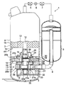
第1の実施形態について、図1に基づいて説明する。図1に示す冷凍サイクル装置1は、圧縮機本体2と第1アキュムレータ3とを有して作動流体であるガス冷媒を圧縮する多段圧縮機4と、圧縮機本体2に接続されて圧縮機本体2から吐出された高圧のガス冷媒を凝縮して液冷媒にする凝縮器5と、凝縮器5に接続されて液冷媒を減圧する膨張装置6と、膨張装置6と第1アキュムレータ3との間に接続されて液冷媒を蒸発させる蒸発器7とを有している。
第1の実施形態について、図1に基づいて説明する。図1に示す冷凍サイクル装置1は、圧縮機本体2と第1アキュムレータ3とを有して作動流体であるガス冷媒を圧縮する多段圧縮機4と、圧縮機本体2に接続されて圧縮機本体2から吐出された高圧のガス冷媒を凝縮して液冷媒にする凝縮器5と、凝縮器5に接続されて液冷媒を減圧する膨張装置6と、膨張装置6と第1アキュムレータ3との間に接続されて液冷媒を蒸発させる蒸発器7とを有している。
第1アキュムレータ3と圧縮機本体2とは、ガス冷媒を後述する低段圧縮要素に導く吸込管8により接続されている。
圧縮機本体2は、円筒状に形成された密閉ケース9を有し、密閉ケース9内には、上部側に位置する電動機部10と、下部側に位置する圧縮機構部11とが収容されている。
これらの電動機部10と圧縮機構部11とは、上下方向の中心線回りに回転する回転軸12を介して連結されている。
電動機部10は、圧縮機構部11を駆動する部分であり、回転軸12に固定された回転子13と、密閉ケース9に固定されて回転子13を囲む位置に配置された固定子14とを有している。
回転子13には永久磁石(図示せず)が設けられ、固定子14には通電用のコイル(図示せず)が巻かれている。
回転軸12における圧縮機構部11を挟んだ上下両側の位置には、回転軸12を回転可能に軸支する主軸受15と副軸受16とが設けられている。
圧縮機構部11は、ガス冷媒を圧縮する部分であり、低圧のガス冷媒を中間圧に圧縮する低段圧縮要素17と、低段圧縮要素17で圧縮された中間圧のガス冷媒を高圧に圧縮する高段圧縮要素18とを有し、これらの低段圧縮要素17と高段圧縮要素18との間は仕切板19により仕切られている。
低段圧縮要素17は、第1シリンダ20aを有し、この第1シリンダ20aの下端側が副軸受16により閉塞され、第1シリンダ20aの上端側が仕切板19により閉塞されている。
この結果、第1シリンダ20a内には、第1シリンダ20aの上下両端を仕切板19と副軸受16とにより閉塞された第1シリンダ室21aが形成される。
第1シリンダ室21a及び後述する第2シリンダ室には回転軸12が貫通されており、回転軸12における第1シリンダ室21a内に位置する部分に第1偏心部22aが形成され、第1偏心部22aには第1ローラ23aが嵌合されている。
第1ローラ23aは、回転軸12の回転時にその外周面を第1シリンダ20aの内周面に線接触させながら偏心回転するように配置されている。
低段圧縮要素17は、これらの第1シリンダ20a、第1偏心部22a、第1ローラ23a、第1シリンダ室21a内を二つの空間(吸込室と圧縮室)に仕切るブレード(図示せず)等により構成されている。
高段圧縮要素18の基本的な構成は、上述した低段圧縮要素17と同じである。
第2シリンダ20bを有し、この第2シリンダ20bの下端側が仕切板19により閉塞され、第2シリンダ20bの上端側が主軸受15により閉塞されている。
第2シリンダ20b内には、第2シリンダ20bの上下両端を主軸受15と仕切板19とにより閉塞された第2シリンダ室21bが形成されている。
第2シリンダ室21bには回転軸12が貫通されており、回転軸12における第2シリンダ室21b内に位置する部分に第2偏心部22bが形成され、第2偏心部22bには第2ローラ23bが嵌合されている。
第2ローラ23bは、回転軸12の回転時にその外周面を第2シリンダ20bの内周面に線接触させながら偏心回転するように配置されている。高段圧縮要素18は、これらの第2シリンダ20b、第2偏心部22b、第2ローラ23b、第2シリンダ室21b内を二つの空間(吸込室と圧縮室)に仕切るブレード(図示せず)等により構成されている。
また、主軸受15には、高段圧縮要素18において圧縮されたガス冷媒を吐出させる吐出弁装置24と、吐出弁装置24を覆う位置に配置されて吐出弁装置24からガス冷媒が吐出される略カップ状のマフラ25とが取付けられている。マフラ25には、マフラ25内に吐出されたガス冷媒を密閉ケース9内に流出させる連通孔26が形成されている。
仕切板19は、回転軸12の軸方向に二つに分割された分割仕切板19a、19bを連結して形成され、仕切板19の内部には仕切板内中間圧空間27が形成されている。
この仕切板内中間圧空間27は、一方の分割仕切板19aを平板状に形成するとともに、他方の分割仕切板19bに凹状の凹み部を形成し、二つの分割仕切板19a、19bを連結することにより形成されている。なお、各分割仕切板19a、19bの両方に凹状の凹み部を形成し、二つの分割仕切板19a、19bを連結してそれらの凹み部を合わせることにより仕切板内中間圧空間27を形成してもよい。
さらに、仕切板19は、回転軸12の軸方向に複数に分割して形成すればよく、三つ以上に分割して形成してもよい。
また、仕切板19には、低段圧縮要素17で圧縮された中間圧のガス冷媒を仕切板内中間圧空間27内に吐出させる吐出弁装置28が設けられている。さらに、高段圧縮要素18に対向する仕切板19の端面には、仕切板内中間圧空間27内のガス冷媒を高段圧縮要素18の第2シリンダ室21bに吸入させる吸入ポート29が形成されている。
高段圧縮要素18の第2シリンダ20bには、吸入ポート29と第2シリンダ室21bとを連通させる切欠き30が形成されている。
このような構成において、この多段圧縮機4においては、電動機部10に通電することにより回転軸12が中心線回りに回転し、回転軸12の回転により圧縮機構部11が駆動される。
圧縮機構部11が駆動されると、第1アキュムレータ3において気液分離された低圧のガス冷媒が吸込管8を経由して低段圧縮要素17の第1シリンダ室21a内に導かれる。
第1シリンダ室21a内に導かれた低圧のガス冷媒は低段圧縮要素17において圧縮され、圧縮されたガス冷媒が所定の中間圧になると吐出弁装置28が開弁され、中間圧のガス冷媒が仕切板内中間圧空間27内に吐出される。
仕切板内中間圧空間27内に吐出された中間圧のガス冷媒は、第2ローラ23bの回転に伴い吸入ポート29と切欠き30とを経由して高段圧縮要素18の第2シリンダ室21b内に流入し、高段圧縮要素18において圧縮され、高圧のガス冷媒となる。
高段圧縮要素18において圧縮されたガス冷媒が所定の高圧になると、吐出弁装置24が開弁され、高圧のガス冷媒がマフラ25内に吐出される。マフラ25内に吐出された高圧のガス冷媒は、連通孔26から密閉ケース9内に流入する。
密閉ケース9内に流入した高圧のガス冷媒は、凝縮器5、膨張装置6、蒸発器7を循環し、低圧のガス冷媒となって再び低段圧縮要素17の第1シリンダ室21a内に導かれる。
仕切板19は、回転軸12の軸方向に二つに分割された分割仕切板19a、19bを連結して形成されている。このため、仕切板19への仕切板内中間圧空間27の形成を容易に行うことができる。さらに、仕切板19に吐出弁装置28を設ける作業は、二つの分割仕切板19a、19bを連結する前に行うことができ、仕切板19に吐出弁装置28を設ける作業を容易に行うことができる。
また、仕切板内中間圧空間27と高段圧縮要素18の第2シリンダ室21bとは、仕切板19の端面に形成された吸入ポート29と第2シリンダ20bに形成された切欠き30とを介して連通されているため、仕切板内中間圧空間27から第2シリンダ室21bまでの流路長さを短くすることができる。このため、中間圧のガス冷媒が仕切板内中間圧空間27から高段圧縮要素18へ吸込まれる場合の吸込み損失を少なくすることができる。
また、仕切板19に設けられた吐出弁装置28は、低段圧縮要素17と高段圧縮要素18との間に挟まれて位置するため、吐出弁装置28の開閉時に発生する音を低段圧縮要素と17と高段圧縮要素18とにより遮音することができ、多段圧縮機4から発生する騒音を低減させることができる。
更に低段圧縮要素17の第1シリンダ室21aと高段圧縮要素18の第2シリンダ室21bとを連通するためのパイプを設ける必要がなく、多段圧縮機4の製造を容易にすることができるとともに製造コストを下げることができる。
(第2の実施形態)
第2の実施形態について、図2に基づいて説明する。なお、第1の実施形態で説明した構成要素と同じ構成要素には同じ符号を付け、重複する説明は省略する。
第2の実施形態について、図2に基づいて説明する。なお、第1の実施形態で説明した構成要素と同じ構成要素には同じ符号を付け、重複する説明は省略する。
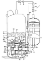
第2の実施形態の多段圧縮機4Aの基本的な構成は、第1の実施形態の多段圧縮機4と同じであり、多段圧縮機4Aが多段圧縮機4と異なる点は、仕切板19に仕切板内中間圧空間27が形成されるとともに、副軸受16に軸受内中間圧空間31が形成されている点である。
軸受内中間圧空間31は、副軸受16の外周部にリング状の外周壁32を形成し、この外周壁32の端部に閉塞板33を固定することにより形成されている。なお、リング状の外周壁32を形成する代わりに、閉塞板33をマフラ25と同様に略カップ状に形成して軸受内中間圧空間31を形成するようにしてもよい。
仕切板内中間圧空間27と軸受内中間圧空間31とは、第1シリンダ20aに形成された貫通路34により連通されている。
副軸受16には、低段圧縮要素17で圧縮された中間圧のガス冷媒を軸受内中間圧空間31内に吐出させる吐出弁装置35が設けられている。
このような構成において、第2の実施形態の多段圧縮機4Aでは、低段圧縮要素17において圧縮されたガス冷媒が所定の中間圧になると吐出弁装置35が開弁され、中間圧のガス冷媒が軸受内中間圧空間31内に吐出される。
吐出されたガス冷媒は貫通路34を介して仕切板内中間圧空間27に導かれ、軸受内中間圧空間31と仕切板内中間圧空間27とに充満される。
軸受内中間圧空間31と仕切板内中間圧空間27とに充満された中間圧のガス冷媒は、第2ローラ23bの回転に伴い吸入ポート29と切欠き30とを経由して高段圧縮要素18の第2シリンダ室21b内に流入し、高段圧縮要素18において圧縮され、高圧のガス冷媒となる。
この多段圧縮機4Aでは、仕切板内中間圧空間27と軸受内中間圧空間31とが形成され、中間圧空間の容積が大きくなっているため、低段圧縮要素17からのガス冷媒の吐出脈動や、高段圧縮要素18へのガス冷媒の吸込脈動を抑制することができる。
(第3の実施形態)
第3の実施形態について、図3に基づいて説明する。なお、第1又は第2の実施形態で説明した構成要素と同じ構成要素には同じ符号を付け、重複する説明は省略する。
第3の実施形態について、図3に基づいて説明する。なお、第1又は第2の実施形態で説明した構成要素と同じ構成要素には同じ符号を付け、重複する説明は省略する。
第3の実施形態の多段圧縮機4Bの基本的な構成は、第2の実施形態の多段圧縮機4Aと同じであり、多段圧縮機4Bと多段圧縮機4Aとの異なる点は、低段圧縮要素17で圧縮された中間圧のガス冷媒を軸受内中間圧空間31内に吐出させる吐出弁装置35が副軸受16に設けられるとともに、低段圧縮要素17で圧縮された中間圧のガス冷媒を仕切板内中間圧空間27内に吐出させる吐出弁装置28が仕切板19に設けられている点である。
さらに、膨張装置6と蒸発器7との間に、第2アキュムレータ41と2つ目の膨張装置42とが設けられている。第2アキュムレータ41と軸受内中間圧空間31との間には、第2アキュムレータ41で気液分離されたガス冷媒を軸受内中間圧空間31を介して仕切板内中間圧空間27内に導くインジェクション管43が設けられている。なお、第2アキュムレータ41で気液分離されたガス冷媒の圧力は、低段圧縮要素17で圧縮された中間圧と略同じ圧力とされている。また、インジェクション管43は仕切板19に接続するようにしてもよい。
インジェクション管43は、第1アキュムレータ3の外周部に固定され、このインジェクション管43と吸込管8とは、圧縮機構部11に対し、密閉ケース9の外周面の法線方向から接続されるとともに、同一の鉛直線上に上下に位置して接続されている。
このような構成において、この多段圧縮機4Bでは、低段圧縮要素17において圧縮されたガス冷媒が所定の中間圧になると吐出弁装置28、35が開弁され、中間圧のガス冷媒が仕切板内中間圧空間27内と軸受内中間圧空間31内とに吐出される。吐出された中間圧のガス冷媒は、第2ローラ23bの回転に伴い吸入ポート29と切欠き30とを経由して高段圧縮要素18の第2シリンダ室21b内に流入し、高段圧縮要素18において圧縮され、高圧のガス冷媒となる。
この多段圧縮機4Bでは、低段圧縮要素17からの中間圧のガス冷媒の吐出が、低段圧縮要素17の両端側に位置する二つの吐出弁装置28、35から行われる。このため、各吐出弁装置28、35からのガス冷媒の吐出量が少なくなり、ガス冷媒が吐出弁装置28、35を通過する際の抵抗損失が小さくなり、多段圧縮機4Bの圧縮性能を高めることができる。
また、この多段圧縮機4Bでは、第2アキュムレータ41が設けられ、第2アキュムレータ41で気液分離された中間圧のガス冷媒をインジェクション管43を介して軸受内中間圧空間31内に導くことにより、多段圧縮機4Bの圧縮性能を高めることができる。
インジェクション管43と吸込管8とは、圧縮機構部11に対し、密閉ケース9の外周面の法線方向から接続されるとともに、同一の鉛直線上に上下に位置して接続されているため、これらのインジェクション管43と吸込管8との接続箇所を自動溶接することが可能となり、多段圧縮機4Bの製造性を向上させることができる。
以上、本発明のいくつかの実施形態を説明したが、これらの実施形態は、例として提示したものであり、発明の範囲を限定することは意図していない。これらの実施形態は、その他の様々な形態で実施されることが可能であり、発明の要旨を逸脱しない範囲で、種々の省略、置き換え、変更を行うことができる。これら実施形態やその変形は、発明の範囲や要旨に含まれると同様に、特許請求の範囲に記載された発明とその均等の範囲に含まれるものである。
1…冷凍サイクル装置、4…多段圧縮機、4A…多段圧縮機、4B…多段圧縮機、5…凝縮器、6…膨張装置、7…蒸発器、8…吸込管、9…密閉ケース、10…電動機部、11…圧縮機構部、12…回転軸、15…主軸受(軸受)、16…副軸受(軸受)、17…低段圧縮要素、18…高段圧縮要素、19…仕切板、19a…分割仕切板、19b…分割仕切板、27…仕切板内中間圧空間、28…吐出弁装置、29…吸入ポート、31…軸受内中間圧空間、35…吐出弁装置、41…第2アキュムレータ、43…インジェクション管
Claims (6)
- 電動機部とこの電動機部に連結された回転軸により駆動される圧縮機構部とが密閉ケース内に収容され、前記圧縮機構部が、低圧の作動流体を中間圧に圧縮する低段圧縮要素と、前記低段圧縮要素で圧縮された中間圧の前記作動流体を高圧に圧縮する高段圧縮要素と、これらの低段圧縮要素と高段圧縮要素との間を仕切る仕切板とを有する多段圧縮機において、
前記仕切板は、前記回転軸の軸方向に複数に分割された分割仕切板を連結して形成され、前記仕切板の内部に前記低段圧縮要素で圧縮された中間圧の前記作動流体が導かれる仕切板内中間圧空間が形成され、前記高段圧縮要素に対向する前記仕切板の端面に前記仕切板内中間圧空間内の前記作動流体を前記高段圧縮要素に吸入させる吸入ポートが形成されていることを特徴とする多段圧縮機。 - 前記低段圧縮要素で圧縮された中間圧の前記作動流体を前記仕切板内中間圧空間内に吐出させる吐出弁装置が前記仕切板に設けられていることを特徴とする請求項1記載の多段圧縮機。
- 前記圧縮機構部の両側に回転軸を軸支する軸受が設けられ、前記低段圧縮要素側に位置する一方の前記軸受に前記仕切板内中間圧空間に連通された軸受内中間圧空間が形成され、前記低段圧縮要素で圧縮された中間圧の前記作動流体を前記軸受内中間圧空間内に吐出させる吐出弁装置が前記一方の軸受に設けられていることを特徴とする請求項1記載の多段圧縮機。
- 前記低段圧縮要素で圧縮された中間圧の前記作動流体を前記仕切板内中間圧空間内に吐出させる吐出弁装置が前記仕切板に設けられていることを特徴とする請求項3記載の多段圧縮機。
- 低圧の作動流体を前記低段圧縮要素に導く吸込管と、
中間圧の作動流体を前記仕切板内中間圧空間に導くインジェクション管と、
が設けられ、
前記吸込管と前記インジェクション管とは前記圧縮機構部に対し、前記密閉ケースの外周面の法線方向から接続されるとともに、同一の鉛直線上に位置して接続されていることを特徴とする請求項1ないし4のいずれか一項に記載の多段圧縮機。 - 請求項1ないし5のいずれか一項に記載の多段圧縮機と、前記多段圧縮機に接続される凝縮器と、前記凝縮器に接続される膨張装置と、前記膨張装置と前記多段圧縮機との間に接続される蒸発器とを備えることを特徴とする冷凍サイクル装置。
Priority Applications (1)
| Application Number | Priority Date | Filing Date | Title |
|---|---|---|---|
| CN201480034587.6A CN105339666B (zh) | 2013-08-23 | 2014-06-27 | 多级压缩机及冷冻循环装置 |
Applications Claiming Priority (2)
| Application Number | Priority Date | Filing Date | Title |
|---|---|---|---|
| JP2013-173807 | 2013-08-23 | ||
| JP2013173807A JP6176782B2 (ja) | 2013-08-23 | 2013-08-23 | 多段圧縮機及び冷凍サイクル装置 |
Publications (1)
| Publication Number | Publication Date |
|---|---|
| WO2015025449A1 true WO2015025449A1 (ja) | 2015-02-26 |
Family
ID=52483249
Family Applications (1)
| Application Number | Title | Priority Date | Filing Date |
|---|---|---|---|
| PCT/JP2014/003432 Ceased WO2015025449A1 (ja) | 2013-08-23 | 2014-06-27 | 多段圧縮機及び冷凍サイクル装置 |
Country Status (3)
| Country | Link |
|---|---|
| JP (1) | JP6176782B2 (ja) |
| CN (1) | CN105339666B (ja) |
| WO (1) | WO2015025449A1 (ja) |
Cited By (1)
| Publication number | Priority date | Publication date | Assignee | Title |
|---|---|---|---|---|
| JP2016160793A (ja) * | 2015-02-27 | 2016-09-05 | 東芝キヤリア株式会社 | 回転式圧縮機及び冷凍サイクル装置 |
Families Citing this family (3)
| Publication number | Priority date | Publication date | Assignee | Title |
|---|---|---|---|---|
| JP2018009565A (ja) * | 2016-06-30 | 2018-01-18 | 株式会社デンソー | 多段圧縮機 |
| CN116378957A (zh) * | 2019-08-21 | 2023-07-04 | 东芝开利株式会社 | 多级旋转式压缩机以及冷冻循环装置 |
| CN117212162A (zh) * | 2023-10-24 | 2023-12-12 | 广东美芝精密制造有限公司 | 泵体组件、压缩机及制冷设备 |
Citations (3)
| Publication number | Priority date | Publication date | Assignee | Title |
|---|---|---|---|---|
| JP2000087892A (ja) * | 1998-09-08 | 2000-03-28 | Daikin Ind Ltd | 2段圧縮機及び空気調和装置 |
| JP2008038697A (ja) * | 2006-08-03 | 2008-02-21 | Mitsubishi Electric Corp | 多段回転式圧縮機 |
| JP2009162207A (ja) * | 2008-01-10 | 2009-07-23 | Fujitsu General Ltd | 2段圧縮ロータリ圧縮機 |
Family Cites Families (5)
| Publication number | Priority date | Publication date | Assignee | Title |
|---|---|---|---|---|
| JP2006177226A (ja) * | 2004-12-22 | 2006-07-06 | Hitachi Home & Life Solutions Inc | ロータリ圧縮機及びそれを用いる空気調和機 |
| JP2008286037A (ja) * | 2007-05-16 | 2008-11-27 | Fujitsu General Ltd | ロータリ圧縮機およびヒートポンプシステム |
| CN202301035U (zh) * | 2011-09-30 | 2012-07-04 | 珠海格力电器股份有限公司 | 中间隔板排气的双级压缩机 |
| CN202301036U (zh) * | 2011-09-30 | 2012-07-04 | 珠海格力电器股份有限公司 | 旋转式双级增焓压缩机 |
| CN102705237B (zh) * | 2012-04-27 | 2015-08-26 | 珠海格力电器股份有限公司 | 一种调节双级压缩机中压腔容积大小的结构及其方法 |
-
2013
- 2013-08-23 JP JP2013173807A patent/JP6176782B2/ja active Active
-
2014
- 2014-06-27 CN CN201480034587.6A patent/CN105339666B/zh active Active
- 2014-06-27 WO PCT/JP2014/003432 patent/WO2015025449A1/ja not_active Ceased
Patent Citations (3)
| Publication number | Priority date | Publication date | Assignee | Title |
|---|---|---|---|---|
| JP2000087892A (ja) * | 1998-09-08 | 2000-03-28 | Daikin Ind Ltd | 2段圧縮機及び空気調和装置 |
| JP2008038697A (ja) * | 2006-08-03 | 2008-02-21 | Mitsubishi Electric Corp | 多段回転式圧縮機 |
| JP2009162207A (ja) * | 2008-01-10 | 2009-07-23 | Fujitsu General Ltd | 2段圧縮ロータリ圧縮機 |
Cited By (1)
| Publication number | Priority date | Publication date | Assignee | Title |
|---|---|---|---|---|
| JP2016160793A (ja) * | 2015-02-27 | 2016-09-05 | 東芝キヤリア株式会社 | 回転式圧縮機及び冷凍サイクル装置 |
Also Published As
| Publication number | Publication date |
|---|---|
| CN105339666A (zh) | 2016-02-17 |
| JP6176782B2 (ja) | 2017-08-09 |
| JP2015040555A (ja) | 2015-03-02 |
| CN105339666B (zh) | 2017-10-03 |
Similar Documents
| Publication | Publication Date | Title |
|---|---|---|
| CN103827500B (zh) | 封闭式压缩机以及制冷循环装置 | |
| US10180271B2 (en) | Multiple cylinder rotary compressor and refrigeration cycle apparatus | |
| CN103906928B (zh) | 密闭型旋转式压缩机和制冷循环装置 | |
| WO2013057946A1 (ja) | 2つのシリンダを持ったロータリ圧縮機 | |
| US9748815B2 (en) | Rotary compressor with the balance weight formed with a recess for receiving the head of a rivet | |
| WO2013005568A1 (ja) | 多気筒回転式圧縮機及び冷凍サイクル装置 | |
| JP6176782B2 (ja) | 多段圧縮機及び冷凍サイクル装置 | |
| JP6037563B2 (ja) | 多気筒回転式圧縮機及び冷凍サイクル装置 | |
| JP6419186B2 (ja) | 回転式圧縮機及び冷凍サイクル装置 | |
| JP7360785B2 (ja) | 回転式圧縮機および冷凍サイクル装置 | |
| JP6041721B2 (ja) | 多気筒回転式圧縮機及び冷凍サイクル装置 | |
| JP2007100513A (ja) | 冷媒圧縮機及びその冷媒圧縮機を備えた冷媒サイクル装置 | |
| AU2014316483B2 (en) | Rotary compressor | |
| WO2016139873A1 (ja) | 圧縮機 | |
| JP6275848B2 (ja) | 圧縮機及び冷凍サイクル装置 | |
| JP2003161280A (ja) | 回転式圧縮機 | |
| JP5595324B2 (ja) | 圧縮機 | |
| JP6430904B2 (ja) | 圧縮機及び冷凍サイクル装置 | |
| JP4401365B2 (ja) | ロータリコンプレッサ | |
| JP4401364B2 (ja) | ロータリコンプレッサ | |
| JP6005786B2 (ja) | 密閉型圧縮機及び冷凍サイクル装置 | |
| JP2016061217A (ja) | シリンダ回転型圧縮機 | |
| JP2003161261A (ja) | 圧縮機 | |
| JP2007092738A (ja) | 圧縮機 | |
| JP2004293450A (ja) | 冷媒サイクル装置 |
Legal Events
| Date | Code | Title | Description |
|---|---|---|---|
| WWE | Wipo information: entry into national phase |
Ref document number: 201480034587.6 Country of ref document: CN |
|
| 121 | Ep: the epo has been informed by wipo that ep was designated in this application |
Ref document number: 14837605 Country of ref document: EP Kind code of ref document: A1 |
|
| NENP | Non-entry into the national phase |
Ref country code: DE |
|
| 122 | Ep: pct application non-entry in european phase |
Ref document number: 14837605 Country of ref document: EP Kind code of ref document: A1 |