WO2015022829A1 - 3次元地図表示システム - Google Patents
3次元地図表示システム Download PDFInfo
- Publication number
- WO2015022829A1 WO2015022829A1 PCT/JP2014/068658 JP2014068658W WO2015022829A1 WO 2015022829 A1 WO2015022829 A1 WO 2015022829A1 JP 2014068658 W JP2014068658 W JP 2014068658W WO 2015022829 A1 WO2015022829 A1 WO 2015022829A1
- Authority
- WO
- WIPO (PCT)
- Prior art keywords
- feature
- display system
- map display
- map
- features
- Prior art date
- Legal status (The legal status is an assumption and is not a legal conclusion. Google has not performed a legal analysis and makes no representation as to the accuracy of the status listed.)
- Ceased
Links
Images

Classifications
-
- G—PHYSICS
- G06—COMPUTING OR CALCULATING; COUNTING
- G06T—IMAGE DATA PROCESSING OR GENERATION, IN GENERAL
- G06T17/00—Three dimensional [3D] modelling, e.g. data description of 3D objects
- G06T17/05—Geographic models
-
- G—PHYSICS
- G06—COMPUTING OR CALCULATING; COUNTING
- G06T—IMAGE DATA PROCESSING OR GENERATION, IN GENERAL
- G06T11/00—2D [Two Dimensional] image generation
- G06T11/20—Drawing from basic elements, e.g. lines or circles
- G06T11/203—Drawing of straight lines or curves
-
- G—PHYSICS
- G06—COMPUTING OR CALCULATING; COUNTING
- G06T—IMAGE DATA PROCESSING OR GENERATION, IN GENERAL
- G06T15/00—3D [Three Dimensional] image rendering
- G06T15/10—Geometric effects
- G06T15/40—Hidden part removal
- G06T15/405—Hidden part removal using Z-buffer
-
- G—PHYSICS
- G06—COMPUTING OR CALCULATING; COUNTING
- G06T—IMAGE DATA PROCESSING OR GENERATION, IN GENERAL
- G06T3/00—Geometric image transformations in the plane of the image
- G06T3/40—Scaling of whole images or parts thereof, e.g. expanding or contracting
-
- G—PHYSICS
- G06—COMPUTING OR CALCULATING; COUNTING
- G06T—IMAGE DATA PROCESSING OR GENERATION, IN GENERAL
- G06T2200/00—Indexing scheme for image data processing or generation, in general
- G06T2200/04—Indexing scheme for image data processing or generation, in general involving 3D image data
Definitions
- the present invention relates to a technique for displaying a three-dimensional map that three-dimensionally represents the ground surface and features.
- three-dimensional maps that represent three-dimensional features have become popular.
- the three-dimensional map is highly convenient because it is easy to grasp the three-dimensional shape of the feature.
- This three-dimensional map is drawn by projecting a three-dimensional model of a feature from a viewpoint set in a three-dimensional space.
- depth determination depth test
- hidden surface processing are performed in order to realistically display the sense of depth of the feature. For this reason, buildings that are hidden behind other buildings and cannot be seen from the viewpoint are not drawn. Also, underground structures such as tunnels are not drawn because they are hidden by the ground surface.
- the three-dimensional map may have problems such as difficulty in grasping the positional relationship between buildings, and difficulty in grasping the connection of roads due to the fact that tunnels are not drawn.
- the building is not hidden by other buildings, and the tunnel is expressed by a broken line or the like as disclosed in Patent Document 1, so that the connection of the road can be grasped. It is drawn. That is, in the three-dimensional map, realization of realistic expressions also causes a problem that deteriorates the convenience of the map.
- Patent Document 2 discloses a technique for making a point of interest visible by performing a transparent display on a building in front of the point of interest in a three-dimensional map.
- Patent Documents 3 and 4 disclose a technique for indicating the position of an underground structure on a map by drawing a planar shape of the underground structure on the ground surface.
- Patent Document 2 cannot be applied to the expression of underground structures because it cannot be transmitted through the ground surface when drawing a map.
- the techniques of Patent Documents 3 and 4 are not applicable when the ground surface has a three-dimensional shape including irregularities, such as the position and shape of underground structures. The problem remains that can only be expressed in a plane.
- the present invention has been made to solve the above-described problems, and an object of the present invention is to alleviate the trouble in drawing a three-dimensional map caused by depth determination.
- the apparatus of the present invention is a three-dimensional map display system that displays a three-dimensional map that three-dimensionally represents the ground surface and features.
- a map database for storing map data representing the three-dimensional shape of the ground surface and features;
- a first drawing unit that refers to the map database and performs depth determination to draw the ground surface and features;
- a feature that is at least partially hidden on the ground surface or another feature is used as a target feature, and the drawing result by the first drawing unit is overwritten using the map data.
- a second drawing unit that draws the target feature without performing a depth determination with a drawing result by the first drawing unit; It is characterized by providing.
- the target feature in the present invention is not necessarily set exclusively with the feature drawn by the first drawing unit.
- this tunnel may be included in the feature drawn by the first drawing unit.
- "Draw the target feature without performing depth determination with the drawing result by the first drawing unit” means the depth relationship between the ground surface and the feature drawn by the first drawing unit. This means that the target feature is drawn irrespectively, and the second drawing unit may perform depth determination between the target features.
- the second drawing unit may directly overwrite the target feature on the drawing result by the first drawing unit, or may draw the target separately from the drawing result by the first drawing unit.
- a layer in which the feature is drawn may be generated and superimposed on the drawing result by the first drawing unit.
- the target feature is displayed in front of the drawing result by the first drawing unit.
- an underground structure such as a tunnel of a road
- it can be drawn on the ground surface after drawing the ground surface.
- a building or road hidden by a building in front near the viewpoint position can be used as a target feature so that it can be drawn in front of other buildings. That is, according to the three-dimensional map display system of the present invention, it is possible to alleviate the trouble in drawing a three-dimensional map that is caused by depth determination that a feature is not drawn or is hidden by another feature.
- the present invention is also characterized in that a target feature is drawn based on three-dimensional map data.
- the target feature can be drawn in a state in which the three-dimensional shape is reflected, and the target feature can be displayed without giving a sense of discomfort to the three-dimensional map.
- a 3D map is drawn with various viewpoint positions and line-of-sight directions
- various image data corresponding to these viewpoint positions and line-of-sight directions are used.
- drawing is based on 3D map data, there is an advantage that drawing according to the viewpoint position and line-of-sight direction can be realized without preparing such data. is there.
- the target feature drawn by the second drawing unit can be specified in various ways.
- the map data includes data representing an underground part
- the second drawing unit may identify the target feature based on data representing the underground portion and draw the target feature.
- map data is prepared so that the underground portion is drawn with a line type different from the ground portion such as a broken line or a dotted line
- the portion to be drawn with these lines can be determined as the underground portion. According to the present invention, even if the underground part is not individually designated, it can be treated as a target feature and drawn on the map in a state where the underground part can be visually recognized.
- the underground portion corresponds to, for example, a tunnel, a basement of a building, an underground shopping area, an underground parking lot, or other underground structures.
- the underground part may be a part of one feature data called a road, for example, so that a part of the road is a tunnel, or only the underground part may be prepared as an individual feature. .
- the second drawing unit may specify the target feature based on the determination information and draw the target feature.
- the content of the determination information may be set in advance, for example, or may be set or changed by the user.
- the target feature can be set or changed flexibly.
- data such as a flag indicating whether the feature is a target feature may be prepared. Further, data may be prepared in a format such as a list of target features in which IDs of features to be handled as target features are stored.
- the determination information may be set individually for each feature, or a plurality of features may be set as a group.
- the second drawing unit may identify the target feature based on the type of the feature and draw the target feature.
- the type of the feature examples include a type of a feature existing in the basement such as a tunnel, an underground parking lot, an underground structure such as an underground shopping center, and the like.
- which type of feature the second drawing unit specifies as the target feature may be set in advance, or may be set or changed by the user.
- the target features can be specified collectively for each type of feature.
- a tunnel is drawn as a target feature, but an underground parking lot is not drawn, so that it is possible to flexibly change handling between underground features.
- the type of the feature is not necessarily limited to the underground feature.
- the target feature can be specified in a subdivided unit such that only the national road is the target feature in the road.
- the second drawing unit identifies the target feature based on a vertical or vertical positional relationship with a reference feature specified in advance as a reference for determining the target feature, and draws the target feature You may make it do.
- the type and number of the reference features can be arbitrarily set.
- the ground surface is drawn three-dimensionally like the feature, the ground surface can be set as the reference feature.
- the vertical positional relationship with the reference feature means the vertical positional relationship in the vertical direction.
- the ground surface is compared with the coordinate value of the ground surface and the coordinate value of the constituent point in the vertical direction for each constituent point constituting the polygon of the feature. It is possible to grasp the upper and lower positional relationship.
- the positional relationship before and after the reference feature means whether it is in front of or behind the line of sight with respect to the viewpoint position.
- the target feature can be, for example, a feature below or in front of the reference feature.
- the target feature may be specified based on only one of the vertical relationship and the longitudinal relationship, or may be specified based on both.
- the method of designating the target feature side has been exemplified.
- the side overwritten by the target feature is designated as the reference feature.
- the identification of target features is a matter of identifying which features should be given priority and displayed between the ground surface and each feature, so display between the ground surface and features It is possible to adopt various methods capable of relatively specifying the priorities of. Further, when the method of specifying the target feature based on the context with the reference feature is used, there is an advantage that the target feature can be freely changed depending on the direction of the viewpoint position.
- a mask image generation unit that generates a mask image by projecting only the features designated as those to be drawn in front of the target features under the same projection conditions as the first drawing unit;
- the second drawing unit may draw the target feature while prohibiting drawing of the target feature in a portion corresponding to the mask image.
- the designation of the feature to be drawn in front of the target feature can take various aspects described above for specifying the target feature. Even in the case of the target feature, there is a case where it is desired to display a part of the target feature while being hidden by a specific other feature. For example, when the target feature is a tunnel, the tunnel is displayed in front of the ground surface, and in addition, it is displayed in front of the tunnel to avoid being displayed as if the tunnel penetrates the building. You may want to display the building. In such a case, in the tunnel of the road, it is only necessary to prevent the tunnel from being displayed for an area overlapping the building as viewed from the viewpoint. According to the present invention, since the target feature can be prevented from being drawn in the portion corresponding to the mask image, it is possible to display a part of the target feature in a state where it is hidden by other features.
- the third drawing unit may draw the designated feature (hereinafter referred to as the designated feature) directly on the drawing result of the first drawing unit and the second drawing unit, or the first drawing Separately from the drawing results of the first drawing unit and the second drawing unit, a layer on which the designated feature is drawn may be generated and superimposed on the drawing results of the first drawing unit and the second drawing unit.
- the third drawing unit draws the feature by performing depth determination between the designated features. Also according to the present invention, it is possible to display in a state where a part of the target feature is hidden by another feature. Also in this aspect, the designated feature can take various methods described above for specifying the target feature.
- the third drawing unit draws the designated features while ignoring the depth relationship with the first drawing unit and the second drawing unit, when there are a large number of designated features, the sense of depth as a three-dimensional map. May be greatly impaired.
- a method for avoiding such trouble a method can be used in which the designated feature drawn by the third drawing unit can be individually designated using the determination information described above.
- the second drawing unit may perform depth determination between the target features and draw the target features.
- the viewpoint For example, when tunnels are used as target features, in locations where there are multiple tunnels, it is possible to grasp the positional relationship between these tunnels by drawing the target features by determining the depth between these tunnels. Display can be realized.
- the present invention does not necessarily have all of the various features described above, and can be configured by omitting some of them or combining them appropriately. Further, the present invention can be configured as an invention of a three-dimensional map display method in addition to the configuration as the above-described three-dimensional map display system. Further, the present invention can be realized in various modes such as a computer program that realizes these, a recording medium that records the program, and a data signal that includes the program and is embodied in a carrier wave. In addition, in each aspect, it is possible to apply the various additional elements shown above.
- the entire program for controlling the operation of the three-dimensional map display system may be configured, or only the portion that performs the function of the present invention. It is good also as what comprises.
- Recording media include flexible disks, CD-ROMs, DVD-ROMs, magneto-optical disks, IC cards, ROM cartridges, punched cards, printed products printed with codes such as barcodes, computer internal storage devices (RAM and Various types of computer-readable media such as a memory such as ROM and an external storage device can be used.
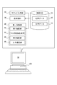
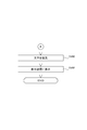
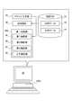
- FIG. 1 is an explanatory diagram showing a schematic configuration of a three-dimensional map display system 100 of the first embodiment.
- the three-dimensional map display system 100 includes a map database (DB) 10, a command input unit 20, a transmission / reception unit 30, a display control unit 40, and a display device 50.
- DB map database
- Each of these functional blocks can be configured by software by installing a computer program for realizing each function in a personal computer including a CPU, RAM, ROM, hard disk drive, communication device, and the like. You may make it comprise at least one part of these functional blocks by hardware.
- the map database 10 stores map data 12 and character data 14.
- the map data 12 is data for displaying a three-dimensional map.
- a three-dimensional model (polygon or line) representing a three-dimensional shape of various features such as the sea, mountains, rivers, roads, and buildings and the ground surface is displayed. Contains. The contents of the map data 12 will be described later.
- the character data 14 is data representing characters drawn in the three-dimensional map, for example, building names, road names, intersection names, and the like.
- the character data 14 is associated with the map data 12.
- the character data 14 includes data describing the display position of each character in the 3D map, the font and size of the character, and the relationship between the scale of the 3D map and the display / non-display of the character.
- the command input unit 10 inputs a user instruction regarding display of a three-dimensional map.
- the command input unit 10 inputs, for example, the scale of the three-dimensional map, the viewpoint position, the line-of-sight direction, and the like.
- the transmission / reception unit 30 exchanges data with other devices via a network (not shown). For example, the transmission / reception unit 30 receives the map data 12 and the character data 14 from another device, updates the map database 10, and outputs the three-dimensional map generated by the display control unit 40 to the printer.
- the display control unit 40 includes a first drawing unit 42, a mask image generation unit 44, a second drawing unit 46, and a character drawing unit 48.
- the first drawing unit 42 performs depth determination and hidden surface processing using the map data 12 read from the map database 10, and draws the ground surface and the feature.
- the mask image generation unit 44 uses the map data 12 to generate a mask image for partially prohibiting the drawing of features by the second drawing unit 46.
- the mask image generation unit 44 projects only the three-dimensional model of the building on the ground under the same projection conditions as the first drawing unit 42, thereby overlapping the building on the ground as seen from the viewpoint. A mask image for prohibiting drawing of underground features in the region is generated.
- the second drawing unit 46 uses the map data 12 as a target feature that is at least partly hidden by the ground surface or other features when drawn by the first drawing unit 42, and uses the first drawing unit
- the target feature is drawn without performing depth determination and hidden surface processing with the drawing result by the first drawing unit 42 so as to overwrite the drawing result by 42.
- the second drawing unit 46 performs drawing by overwriting the target feature on the drawing result by the first drawing unit 42.
- the second drawing unit 46 may generate a layer in which the target feature is drawn separately from the drawing result by the first drawing unit 42 and superimpose the layer on the drawing result by the first drawing unit 42.
- the second drawing unit 46 draws the target features by performing depth determination and hidden surface processing between the target features.
- the character drawing unit 48 draws characters on the three-dimensional map using the character data 14 read from the map database 10.
- the display control unit 40 controls the operations of the first drawing unit 42, the mask image generation unit 44, the second drawing unit 46, and the character drawing unit 48, and displays a three-dimensional map drawn by these on the display device 50.
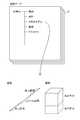
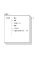
- FIG. 2 is an explanatory diagram showing the contents of the map data 12.
- a unique feature ID is assigned to each feature, and various data are managed for each feature.
- the ground surface is divided into mesh shapes, and each is managed with a unique ID, as with the features.
- “Type” represents the type of a feature such as sea, mountain, river, road, railroad, and building. For roads and railways, the ground section (ground part) and tunnel section (underground part) are managed as one feature, and the tunnel section is assigned a sub-type indicating an underground structure. Yes.
- the building is managed as one feature in both the above-ground part and the underground part, and a sub-type indicating that it is an underground structure is assigned to the underground part of the building.
- a type indicating an underground structure is assigned to an underground structure such as an underground parking lot or an underground mall.
- the ground section and the underground section may be managed as separate features.
- a type of ground surface is assigned to the map data 12 of the ground surface. “Name” is the name of the feature.
- the “three-dimensional model” is polygon data for displaying the ground surface and various features in three dimensions, or line data for displaying roads and railways.
- the ground features and the ground portions of the features are drawn by solid lines, and the underground portions and underground structures of the features are drawn by broken lines.
- the ground section of the road is drawn with a solid line
- the tunnel section is drawn with a broken line.
- the ground part of the building is drawn with a solid line
- the underground part is drawn with a broken line.
- the ground features and the ground portions of the features are collectively referred to as ground features.
- the underground part and underground structure of a feature are collectively called an underground feature.
- Coordinats are coordinate data of each constituent point of the three-dimensional model (polygon data or line data).
- Textture is an image that is pasted in accordance with the shape of a feature (three-dimensional model) in texture mapping. In this embodiment, since the underground feature is drawn transparently, the texture of the underground feature is not prepared.
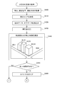
- 3D map display processing 3 to 5 are flowcharts showing the flow of the 3D map display process of the first embodiment.
- This process is a process executed by the 3D map display system 100 when a 3D map display instruction is input.
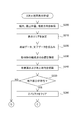
- the 3D map display system 100 acquires the scale, viewpoint position, and line-of-sight direction of the 3D map specified by the user (step S100).
- the 3D map display system 100 determines a display area based on the scale, viewpoint position, and line-of-sight direction of the acquired 3D map (Step S110), and the surface and features existing in the display area are determined.
- the map data 12 and the character data 14 are read (step S120).
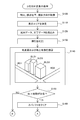
- the three-dimensional map display system 100 discriminates the type of each map data 12 (step S130), and features without the subtype “underground structure”, that is, the ground surface and the ground features , And drawing by performing depth determination and hidden surface processing using a Z buffer (depth buffer) (step S140) (hereinafter, this drawing result is referred to as “normal drawing”).
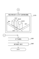
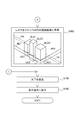
- a three-dimensional map in which roads RD1, RD2 and buildings BLD1, BLD2, BLD3 as the ground surface and ground features are drawn in the frame of step S140 is shown.
- the road includes a ground portion and a tunnel as one feature data
- the building includes a ground portion and an underground portion as one feature data.
- step S140 from these feature data, only the constituent points and polygons corresponding to the ground features are extracted and drawn. In the drawing with depth determination, the underground feature is not drawn because it is hidden on the ground surface. Therefore, in the process of step S140, the process of extracting only the ground feature is omitted, and all the features are drawn. Good.
- the three-dimensional map display system 100 determines whether or not an underground feature exists in the display area based on the determination result in step S130 (step S150).
- step S150 NO
- the 3D map display system 100 advances the process to step S190.
- step S150 YES
- the 3D map display system 100 clears the Z buffer before drawing the underground feature (step S160). By doing so, in the subsequent drawing process of the underground feature, the depth determination and the hidden surface process are not performed between the drawing result (normal drawing) in step S140.
- the extraction of underground features in step S150 may take a method other than the type.
- the ground features are drawn as solid lines, and the underground features are drawn as broken lines. Therefore, the underground features are extracted based on the type of line used for drawing. You may do it. In addition, it may be extracted based on features on data representing underground features such as the presence or absence of texture.
- the 3D map display system 100 draws the underground feature so as to overwrite the normal drawing.
- depth determination is not performed between normal drawing and the building on the ground may be obscured by the underground feature depending on the positional relationship between the underground feature and the building on the ground. Can occur. Therefore, in this embodiment, in order to avoid such a state, the underground feature is not displayed in the portion where the building on the ground is drawn. In other words, the underground feature is drawn as if the depth determination is made between the building on the ground and the underground feature.
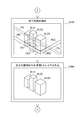
- the 3D map display system 100 projects only the building on the ground under the same projection conditions as in step S140, and generates a stencil mask SM as a mask image (step S170).
- a stencil mask SM having a mask region MK generated by projecting only the buildings BLD1, BLD2, and BLD3 on the ground is shown in the frame of step S170.
- the mask area MK in the stencil mask SM is shown in black.
- the designation of the feature to be projected when generating the stencil mask SM can be arbitrarily changed.
- the 3D map display system 100 extracts the underground features based on the determination result in step S130, and prohibits the drawing on the mask area MK overlapping the buildings BLD1, BLD2, BLD3 on the ground by the stencil mask SM,
- the extracted underground feature is overwritten on the drawing result of step S140 and drawn (step S180).
- step S180 a three-dimensional map is shown in which the tunnel TN of the road as an underground feature and the underground parts UG1, UG2, UG3 of the buildings BLD1, BLD2, BLD3 are overwritten.
- the underground feature is drawn only with a broken line.
- the tunnel TN is a part of the road, and the three-dimensional model of the road is managed by line data.
- the line data has a width corresponding to the scale, viewpoint position, and line-of-sight direction of the 3D map acquired in step S100, and is converted into a polygon.
- the edge is drawn with a broken line.
- Depth determination is performed between the ground buildings BLD1, BLD2, BLD3 and the underground features by drawing the underground features using the stencil mask SM generated by projecting only the buildings BLD1, BLD2, BLD3.
- the underground features can be displayed as if they are.
- the three-dimensional map display system 100 performs depth determination and hidden surface processing on the underground features.
- the 3D map display system 100 draws characters in the 3D map (step S190), and displays the 3D map on the display device 50 (step S192). Then, the 3D map display system 100 ends the 3D map display process. According to the 3D map display process of the first embodiment described above, an underground feature can be drawn. Accordingly, it is possible to alleviate the trouble in drawing the three-dimensional map caused by the depth determination, and to easily grasp the positional relationship with respect to various features.
- the configuration of the 3D map display system 100 of the second embodiment is the same as the configuration of the 3D map display system 100 of the first embodiment.
- the 3D map display system 100 of the second embodiment differs from the first embodiment in part of the contents of the 3D map display process. That is, in the first embodiment, in the three-dimensional map display process, the underground feature is extracted by referring to the map data 12 and determining the type of each feature. Underground features are extracted by analyzing the coordinates of the component points.
- the 3D map display process of the second embodiment will be described.
- FIGS. 6 and 7 are flowcharts showing the flow of the 3D map display process of the second embodiment.
- This process is a process executed by the 3D map display system 100 when a 3D map display instruction is input.
- the three-dimensional map display system 100 acquires the scale, viewpoint position, and line-of-sight direction (step S200), determines the display area (step S210), and reads the map data 12 and the character data 14 (step S220). Do.
- step S200 acquires the scale, viewpoint position, and line-of-sight direction
- step S210 determines the display area
- step S220 reads the map data 12 and the character data 14
- the coordinate value of the ground surface and the coordinate value of the component point are compared in the vertical direction for each component point of the polygon or line representing the feature. If the coordinate value of the constituent point is larger than the coordinate value of the ground surface, it can be determined that the constituent point is a constituent point of the ground feature, and if the coordinate value of the constituent point is smaller than the coordinate value of the ground surface It can be determined that the constituent point is a constituent point of the underground feature. Then, the 3D map display system 100 extracts the ground portion of the feature based on the analysis result, performs depth determination and hidden surface processing using the Z buffer, and draws the ground surface and the extracted ground portion ( Step S240). The following processing is the same as in the first embodiment.
- step S250 when there is an underground feature (step S250: YES), the 3D map display system 100 clears the Z buffer (step S260) and generates a stencil mask SM (step S270). Using this, the underground feature is drawn (step S280). When there is no underground feature (step S250), these processes are skipped. Thereafter, the 3D map display system 100 draws characters (step S290) and displays a 3D map (step S292). According to the second embodiment described above, the underground feature can be drawn without setting the type representing the underground feature.
- the configuration of the 3D map display system 100 of the third embodiment is a configuration in which the mask image generation unit 44 is excluded from the configuration of the 3D map display system 100 of the first embodiment.
- the 3D map display system 100 of the third embodiment is different from the first embodiment in the map data 12a stored in the map database 10 and part of the contents of the 3D map display processing.
- the contents of the map data 12a and the 3D map display process in the third embodiment will be described.
- FIG. 8 is an explanatory diagram showing the contents of the map data 12a in the third embodiment.
- a “target feature determination flag” is attached to each feature.
- the “target feature determination flag” is determination information indicating whether or not the feature is a drawing target by the second drawing unit 46, that is, whether or not it is a drawing target after clearing the Z buffer. “1” is set to “0” when the drawing target is not set.
- the “target feature determination flag” may be set in advance by the provider of the map data 12a, or may be set or changed by the user. In the present embodiment, the drawing objects by the second drawing unit 46 can be set or changed individually and flexibly.
- FIGS 9 and 10 are flowcharts showing the flow of the 3D map display process of the third embodiment.
- This process is a process executed by the 3D map display system 100 when a 3D map display instruction is input.
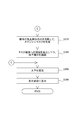
- the three-dimensional map display system 100 acquires the scale, viewpoint position, and line-of-sight direction (step S300), determines the display area (step S310), and reads the map data 12 and the character data 14 (step S320). Do.
- the three-dimensional map display system 100 refers to the target feature determination flag in the map data 12 (step S330), and uses the Z buffer for the feature and the ground surface whose target feature determination flag is “0”. Drawing is performed by depth determination and hidden surface processing (step S340).
- step S340 A three-dimensional map in which roads RD1, RD2 and buildings BLD1, BLD2, BLD3 as features having a ground surface and a target feature determination flag of “0” are drawn in the frame of step S340 is shown.
- step S350 YES
- the 3D map display system 100 clears the Z buffer (step S360).
- the feature is overwritten on the drawing result obtained in step S340 (step S370), the character is drawn (step S380), and displayed on the display device (step S390).
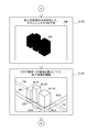
- step S370 the building BLD2 as the feature having the target feature determination flag “1” and its underground portion UG2 are overwritten and the three-dimensional map is drawn.
- the building BLD2 and the underground portion UG2 can be displayed with priority over other features such as the building BLD3.
- the building BLD2 can be displayed so as to be immediately visible in the three-dimensional map, the display is useful when the building BLD2 is a destination designated by the user or a landmark.
- the target feature determination flag is set for each feature, the building BLD2 and the underground portion UG2 are integrated and treated as being preferentially drawn.
- the building BLD2 and the underground portion UG2 are separated into different feature data, What is necessary is just to set a target feature determination flag for each.
- a structure in which a target feature determination flag can be set for each part of the feature data as in the first embodiment can be set.
- the underground feature is drawn using the stencil mask SM while prohibiting drawing on the mask area MK.
- the 3D map display system 100A of the fourth embodiment the entire underground feature is overwritten on the drawing result of the ground feature, and further overwritten on the drawing result. By drawing only the buildings on the ground, at least a part of the underground features is hidden and displayed by the buildings on the ground.
- FIG. 11 is an explanatory diagram showing a schematic configuration of a 3D map display system 100A of the fourth embodiment.
- a 3D map display system 100A according to the fourth embodiment includes a display control unit 40A instead of the display control unit 40 in the 3D map display system 100 according to the first embodiment shown in FIG.
- the display control unit 40 ⁇ / b> A includes a third drawing unit 47 instead of the mask image generation unit 44 in the display control unit 40.
- the rest is the same as the 3D map display system 100 of the first embodiment.
- the third drawing unit 47 draws only the building on the ground (the ground portion of the building) so as to overwrite the drawing result by the second drawing unit 46.
- the third drawing unit 47 generates a layer in which only the building on the ground is drawn separately from the drawing results by the first drawing unit 42 and the second drawing unit 46, and this is generated as the first drawing unit 42 and The image is superimposed on the drawing result by the second drawing unit 46.
- the third drawing unit 47 may draw the building on the ground by overwriting the drawing results obtained by the first drawing unit 42 and the second drawing unit 46.
- step S400 obtains the scale, viewpoint position, and line-of-sight direction (step S400), determines the display area (step S410), and reads the map data 12 and the character data 14 (step S420). Do. These are the same processes as in the first embodiment. Also, the 3D map display system 100A determines the type of each map data 12 (step S430), extracts the ground surface and ground features, and uses the Z buffer to perform depth determination and hidden surface, as in the first embodiment.
- step S440 Processing is performed to draw the extracted ground surface and ground features (step S440).
- step S450 when there is an underground feature in the display area (step S450: YES), the 3D map display system 100A clears the Z buffer (step S460), and draws the underground feature in step S440. The result is overwritten and drawn (step S470).
- step S170 the processing contents are the same as those in the first embodiment.
- step S470 the output result when the processing of step S470 is completed is different from that of the first embodiment.
- a three-dimensional map is shown in which the road tunnel TN as an underground feature and the underground parts UG1, UG2, UG3 of the buildings BLD1, BLD2, BLD3 are overwritten in the frame of step S470.
- an underground feature such as the tunnel TN is drawn so as to penetrate the ground building BLD1 and the like drawn earlier.
- the 3D map display system 100A generates a drawn layer by projecting only the building on the ground (the ground portion of the building) under the same projection conditions as in step S440, apart from the drawing result in step S470 (step S440). S480).
- the 3D map display system 100A also performs depth determination between buildings on the ground.
- step S482 the 3D map display system 100A superimposes this layer on the drawing result obtained in step S470 (step S482).
- the underground feature can be displayed as if the depth determination is performed between the buildings BLD1, BLD2, BLD3 on the ground and the underground feature.
- step S450: NO these processes are skipped.
- the 3D map display system 100A draws characters (step S490) and displays them on the display device (step S492). According to the 3D map display process of the fourth embodiment described above, the same drawing as that of the first embodiment can be realized without using the stencil mask SM.
- the ground surface and ground features are drawn (step S440) ⁇ the Z buffer is cleared (step S460) ⁇ the underground features are drawn (step S470). ) ⁇ 3D map drawing is performed in the order of superimposing layers on which only buildings on the ground are drawn (steps S480 and 482), but the present invention is not limited to this. Drawing the ground surface and ground features ⁇ clearing the Z buffer ⁇ drawing underground features ⁇ clearing the Z buffer ⁇ drawing buildings on the ground may be performed in the order of drawing. In this way, the underground feature can be displayed as if the depth determination is performed between the building on the ground (the ground portion of the building) and the underground feature.
- the various processes described in the above embodiments and modifications are not necessarily all provided, and some of them may be omitted, replaced with other processes, or combined.
- the mask image generation unit 44 may be omitted.
- the 3D map display system 100A of the second embodiment the third drawing unit 47 may be omitted.
- the 3D map display process of the first embodiment or the second embodiment may be combined with the 3D map display process of the third embodiment.
- the 3D map display process of the third embodiment and the 3D map display process of the fourth embodiment may be combined.
- the target feature to be drawn after the Z buffer is cleared is not necessarily limited to the underground feature. It is also possible to apply the 3D map display systems 100 and 100A of the above embodiment to a navigation system that performs route guidance using a 3D map.
- the processing executed in software may be executed in hardware and vice versa.
- the present invention can be used for a technique for displaying a three-dimensional map that three-dimensionally represents the ground surface and features.
Landscapes
- Engineering & Computer Science (AREA)
- Physics & Mathematics (AREA)
- General Physics & Mathematics (AREA)
- Theoretical Computer Science (AREA)
- Geometry (AREA)
- Software Systems (AREA)
- Computer Graphics (AREA)
- Remote Sensing (AREA)
- Processing Or Creating Images (AREA)
- Instructional Devices (AREA)
- Navigation (AREA)
- Radar, Positioning & Navigation (AREA)
- Computer Hardware Design (AREA)
- General Engineering & Computer Science (AREA)
Priority Applications (4)
| Application Number | Priority Date | Filing Date | Title |
|---|---|---|---|
| KR1020157036066A KR102214906B1 (ko) | 2013-08-12 | 2014-07-14 | 3차원 지도 표시 시스템 |
| EP14836758.4A EP3035293A4 (en) | 2013-08-12 | 2014-07-14 | Three-dimensional map display system |
| CN201480043937.5A CN105453140A (zh) | 2013-08-12 | 2014-07-14 | 三维地图显示系统 |
| US15/008,291 US9741164B2 (en) | 2013-08-12 | 2016-01-27 | 3D map display system |
Applications Claiming Priority (2)
| Application Number | Priority Date | Filing Date | Title |
|---|---|---|---|
| JP2013167235A JP6244137B2 (ja) | 2013-08-12 | 2013-08-12 | 3次元地図表示システム |
| JP2013-167235 | 2013-08-12 |
Related Child Applications (1)
| Application Number | Title | Priority Date | Filing Date |
|---|---|---|---|
| US15/008,291 Continuation US9741164B2 (en) | 2013-08-12 | 2016-01-27 | 3D map display system |
Publications (1)
| Publication Number | Publication Date |
|---|---|
| WO2015022829A1 true WO2015022829A1 (ja) | 2015-02-19 |
Family
ID=52468219
Family Applications (1)
| Application Number | Title | Priority Date | Filing Date |
|---|---|---|---|
| PCT/JP2014/068658 Ceased WO2015022829A1 (ja) | 2013-08-12 | 2014-07-14 | 3次元地図表示システム |
Country Status (6)
| Country | Link |
|---|---|
| US (1) | US9741164B2 (enExample) |
| EP (1) | EP3035293A4 (enExample) |
| JP (1) | JP6244137B2 (enExample) |
| KR (1) | KR102214906B1 (enExample) |
| CN (1) | CN105453140A (enExample) |
| WO (1) | WO2015022829A1 (enExample) |
Families Citing this family (7)
| Publication number | Priority date | Publication date | Assignee | Title |
|---|---|---|---|---|
| WO2017199999A1 (ja) * | 2016-05-20 | 2017-11-23 | アイシン・エィ・ダブリュ株式会社 | 地図表示システムおよび地図表示プログラム |
| JP2018111982A (ja) * | 2017-01-11 | 2018-07-19 | 株式会社不動テトラ | 地盤改良用施工管理システム |
| JP6967417B2 (ja) * | 2017-10-03 | 2021-11-17 | 株式会社 ミックウェア | 経路生成装置、及びプログラム |
| CN108597021B (zh) * | 2018-04-20 | 2022-03-11 | 武汉地大信息工程股份有限公司 | 一种地上地下三维模型一体化展示方法及系统 |
| KR102273274B1 (ko) * | 2019-11-21 | 2021-07-06 | 한국국토정보공사 | 지상 공간과 대칭되는 지하 공간에 관한 지하 공간 정보 생성 방법 및 장치 |
| US20230377537A1 (en) * | 2020-10-27 | 2023-11-23 | Nippon Telegraph And Telephone Corporation | Display device, display method, and program |
| CN115496869A (zh) * | 2022-09-13 | 2022-12-20 | 北京三快在线科技有限公司 | 地图中隧道道路的显示方法、矢量地形图的获取方法 |
Citations (5)
| Publication number | Priority date | Publication date | Assignee | Title |
|---|---|---|---|---|
| JPH09138136A (ja) | 1995-09-11 | 1997-05-27 | Matsushita Electric Ind Co Ltd | 車載用ナビゲーション装置 |
| JP2003166836A (ja) | 2001-11-30 | 2003-06-13 | Alpine Electronics Inc | 地下建築物立体表示装置 |
| JP2004333155A (ja) | 2003-04-30 | 2004-11-25 | Sony Corp | 情報提示装置及び情報提示方法、並びにコンピュータ・プログラム |
| JP2007026201A (ja) * | 2005-07-19 | 2007-02-01 | Sega Corp | 画像処理装置、道路画像描画方法および道路画像描画プログラム |
| JP2008128928A (ja) | 2006-11-24 | 2008-06-05 | Xanavi Informatics Corp | 車載地図表示装置、ナビゲーション装置 |
Family Cites Families (11)
| Publication number | Priority date | Publication date | Assignee | Title |
|---|---|---|---|---|
| JP3351760B2 (ja) * | 1999-04-07 | 2002-12-03 | 松下電器産業株式会社 | 3次元立体地図描画装置及び描画方法 |
| US6542174B2 (en) * | 1999-12-09 | 2003-04-01 | Matsushita Electric Industrial Co., Ltd. | Map displaying system and map displaying method |
| JP2005195475A (ja) * | 2004-01-07 | 2005-07-21 | Fujitsu Ten Ltd | ナビゲーション装置 |
| JP4468076B2 (ja) * | 2004-06-03 | 2010-05-26 | 三菱電機株式会社 | 地図表示装置 |
| KR100634536B1 (ko) * | 2005-01-25 | 2006-10-13 | 삼성전자주식회사 | 3차원 그래픽스 환경에서의 2차원 고가도로 데이터의 3차원 변환 방법 및 장치, 그리고 이를 이용한 3차원 그래픽스 환경에서의 2차원 고가도로 데이터의 3차원 시각화 방법 및 장치 |
| EP2307854A1 (en) * | 2008-07-31 | 2011-04-13 | Tele Atlas B.V. | Method of displaying navigation data in 3d |
| KR101051310B1 (ko) * | 2009-08-07 | 2011-07-22 | 팅크웨어(주) | 내비게이션 장치 및 내비게이션 장치의 삼차원 맵 표시 방법 |
| US20110225546A1 (en) * | 2010-03-09 | 2011-09-15 | Ramos Gonzalo A | Map spotlights |
| US9552669B2 (en) * | 2010-09-02 | 2017-01-24 | Underground Imaging Technologies, Llc | System, apparatus, and method for utilizing geographic information systems |
| US20130084838A1 (en) * | 2011-10-03 | 2013-04-04 | Geospatial Holdings, Inc. | System, method, and apparatus for viewing underground structures |
| US8411113B1 (en) * | 2011-10-12 | 2013-04-02 | Google Inc. | Layered digital image data reordering and related digital image rendering engine |
-
2013
- 2013-08-12 JP JP2013167235A patent/JP6244137B2/ja not_active Expired - Fee Related
-
2014
- 2014-07-14 KR KR1020157036066A patent/KR102214906B1/ko active Active
- 2014-07-14 CN CN201480043937.5A patent/CN105453140A/zh active Pending
- 2014-07-14 WO PCT/JP2014/068658 patent/WO2015022829A1/ja not_active Ceased
- 2014-07-14 EP EP14836758.4A patent/EP3035293A4/en not_active Withdrawn
-
2016
- 2016-01-27 US US15/008,291 patent/US9741164B2/en not_active Expired - Fee Related
Patent Citations (5)
| Publication number | Priority date | Publication date | Assignee | Title |
|---|---|---|---|---|
| JPH09138136A (ja) | 1995-09-11 | 1997-05-27 | Matsushita Electric Ind Co Ltd | 車載用ナビゲーション装置 |
| JP2003166836A (ja) | 2001-11-30 | 2003-06-13 | Alpine Electronics Inc | 地下建築物立体表示装置 |
| JP2004333155A (ja) | 2003-04-30 | 2004-11-25 | Sony Corp | 情報提示装置及び情報提示方法、並びにコンピュータ・プログラム |
| JP2007026201A (ja) * | 2005-07-19 | 2007-02-01 | Sega Corp | 画像処理装置、道路画像描画方法および道路画像描画プログラム |
| JP2008128928A (ja) | 2006-11-24 | 2008-06-05 | Xanavi Informatics Corp | 車載地図表示装置、ナビゲーション装置 |
Non-Patent Citations (1)
| Title |
|---|
| See also references of EP3035293A4 * |
Also Published As
| Publication number | Publication date |
|---|---|
| US20160140756A1 (en) | 2016-05-19 |
| EP3035293A1 (en) | 2016-06-22 |
| CN105453140A (zh) | 2016-03-30 |
| KR102214906B1 (ko) | 2021-02-09 |
| US9741164B2 (en) | 2017-08-22 |
| KR20160041853A (ko) | 2016-04-18 |
| EP3035293A4 (en) | 2017-03-08 |
| JP6244137B2 (ja) | 2017-12-06 |
| JP2015036824A (ja) | 2015-02-23 |
Similar Documents
| Publication | Publication Date | Title |
|---|---|---|
| JP6244137B2 (ja) | 3次元地図表示システム | |
| US11698268B2 (en) | Street-level guidance via route path | |
| JP4964762B2 (ja) | 地図表示装置および地図表示方法 | |
| US20130057550A1 (en) | Three-dimensional map drawing system | |
| JP4251218B2 (ja) | 情報処理装置、画像表示装置、情報処理システム、および、これらにおける制御方法ならびに当該方法をコンピュータに実行させるプログラム | |
| CN105051791B (zh) | 三维图像输出装置和背景图像生成装置 | |
| JP2009157053A (ja) | 立体地図表示ナビゲーション装置、立体地図表示システム及び立体地図表示プログラム | |
| JP5964771B2 (ja) | 3次元地図表示装置、3次元地図表示方法、および、コンピュータプログラム | |
| JP2009236843A (ja) | ナビゲーション装置、ナビゲーション方法、およびナビゲーションプログラム | |
| JP6022386B2 (ja) | 3次元地図表示装置、3次元地図表示方法、および、コンピュータプログラム | |
| JP5959479B2 (ja) | 3次元地図表示システム | |
| JP6345381B2 (ja) | 拡張現実システム | |
| CN104101357B (zh) | 导航系统以及在导航系统上显示影像地图的方法 | |
| CN101432786B (zh) | 用于导航系统的显示屏幕天空的方法和其装置 | |
| JP5702476B2 (ja) | 表示装置、制御方法、プログラム、記憶媒体 | |
| JP2009020906A (ja) | 地図表示装置、地図上の位置を特定する方法、および、コンピュータプログラム | |
| JP2013161466A (ja) | 3次元地図における地点指定システム | |
| JP2022018015A (ja) | 情報処理装置及びプログラム | |
| JP2006221199A (ja) | 3次元地図表示装置 |
Legal Events
| Date | Code | Title | Description |
|---|---|---|---|
| WWE | Wipo information: entry into national phase |
Ref document number: 201480043937.5 Country of ref document: CN |
|
| 121 | Ep: the epo has been informed by wipo that ep was designated in this application |
Ref document number: 14836758 Country of ref document: EP Kind code of ref document: A1 |
|
| ENP | Entry into the national phase |
Ref document number: 20157036066 Country of ref document: KR Kind code of ref document: A |
|
| NENP | Non-entry into the national phase |
Ref country code: DE |
|
| REEP | Request for entry into the european phase |
Ref document number: 2014836758 Country of ref document: EP |
|
| WWE | Wipo information: entry into national phase |
Ref document number: 2014836758 Country of ref document: EP |