WO2015020144A1 - Co2選択透過膜及びco2を混合ガスから分離する方法 - Google Patents
Co2選択透過膜及びco2を混合ガスから分離する方法 Download PDFInfo
- Publication number
- WO2015020144A1 WO2015020144A1 PCT/JP2014/070855 JP2014070855W WO2015020144A1 WO 2015020144 A1 WO2015020144 A1 WO 2015020144A1 JP 2014070855 W JP2014070855 W JP 2014070855W WO 2015020144 A1 WO2015020144 A1 WO 2015020144A1
- Authority
- WO
- WIPO (PCT)
- Prior art keywords
- membrane
- ionic liquid
- gas
- group
- permselective membrane
- Prior art date
- Legal status (The legal status is an assumption and is not a legal conclusion. Google has not performed a legal analysis and makes no representation as to the accuracy of the status listed.)
- Ceased
Links
Images




Classifications
-
- C—CHEMISTRY; METALLURGY
- C07—ORGANIC CHEMISTRY
- C07C—ACYCLIC OR CARBOCYCLIC COMPOUNDS
- C07C229/00—Compounds containing amino and carboxyl groups bound to the same carbon skeleton
- C07C229/02—Compounds containing amino and carboxyl groups bound to the same carbon skeleton having amino and carboxyl groups bound to acyclic carbon atoms of the same carbon skeleton
- C07C229/04—Compounds containing amino and carboxyl groups bound to the same carbon skeleton having amino and carboxyl groups bound to acyclic carbon atoms of the same carbon skeleton the carbon skeleton being acyclic and saturated
- C07C229/06—Compounds containing amino and carboxyl groups bound to the same carbon skeleton having amino and carboxyl groups bound to acyclic carbon atoms of the same carbon skeleton the carbon skeleton being acyclic and saturated having only one amino and one carboxyl group bound to the carbon skeleton
- C07C229/08—Compounds containing amino and carboxyl groups bound to the same carbon skeleton having amino and carboxyl groups bound to acyclic carbon atoms of the same carbon skeleton the carbon skeleton being acyclic and saturated having only one amino and one carboxyl group bound to the carbon skeleton the nitrogen atom of the amino group being further bound to hydrogen atoms
-
- B—PERFORMING OPERATIONS; TRANSPORTING
- B01—PHYSICAL OR CHEMICAL PROCESSES OR APPARATUS IN GENERAL
- B01D—SEPARATION
- B01D53/00—Separation of gases or vapours; Recovering vapours of volatile solvents from gases; Chemical or biological purification of waste gases, e.g. engine exhaust gases, smoke, fumes, flue gases, aerosols
- B01D53/22—Separation of gases or vapours; Recovering vapours of volatile solvents from gases; Chemical or biological purification of waste gases, e.g. engine exhaust gases, smoke, fumes, flue gases, aerosols by diffusion
- B01D53/228—Separation of gases or vapours; Recovering vapours of volatile solvents from gases; Chemical or biological purification of waste gases, e.g. engine exhaust gases, smoke, fumes, flue gases, aerosols by diffusion characterised by specific membranes
-
- B—PERFORMING OPERATIONS; TRANSPORTING
- B01—PHYSICAL OR CHEMICAL PROCESSES OR APPARATUS IN GENERAL
- B01D—SEPARATION
- B01D61/00—Processes of separation using semi-permeable membranes, e.g. dialysis, osmosis or ultrafiltration; Apparatus, accessories or auxiliary operations specially adapted therefor
- B01D61/38—Liquid-membrane separation
-
- B—PERFORMING OPERATIONS; TRANSPORTING
- B01—PHYSICAL OR CHEMICAL PROCESSES OR APPARATUS IN GENERAL
- B01D—SEPARATION
- B01D69/00—Semi-permeable membranes for separation processes or apparatus characterised by their form, structure or properties; Manufacturing processes specially adapted therefor
- B01D69/10—Supported membranes; Membrane supports
-
- B—PERFORMING OPERATIONS; TRANSPORTING
- B01—PHYSICAL OR CHEMICAL PROCESSES OR APPARATUS IN GENERAL
- B01D—SEPARATION
- B01D69/00—Semi-permeable membranes for separation processes or apparatus characterised by their form, structure or properties; Manufacturing processes specially adapted therefor
- B01D69/14—Dynamic membranes
- B01D69/141—Heterogeneous membranes, e.g. containing dispersed material; Mixed matrix membranes
- B01D69/142—Heterogeneous membranes, e.g. containing dispersed material; Mixed matrix membranes with "carriers"
-
- B—PERFORMING OPERATIONS; TRANSPORTING
- B01—PHYSICAL OR CHEMICAL PROCESSES OR APPARATUS IN GENERAL
- B01D—SEPARATION
- B01D71/00—Semi-permeable membranes for separation processes or apparatus characterised by the material; Manufacturing processes specially adapted therefor
- B01D71/06—Organic material
-
- C—CHEMISTRY; METALLURGY
- C07—ORGANIC CHEMISTRY
- C07C—ACYCLIC OR CARBOCYCLIC COMPOUNDS
- C07C211/00—Compounds containing amino groups bound to a carbon skeleton
- C07C211/62—Quaternary ammonium compounds
- C07C211/63—Quaternary ammonium compounds having quaternised nitrogen atoms bound to acyclic carbon atoms
-
- B—PERFORMING OPERATIONS; TRANSPORTING
- B01—PHYSICAL OR CHEMICAL PROCESSES OR APPARATUS IN GENERAL
- B01D—SEPARATION
- B01D2256/00—Main component in the product gas stream after treatment
- B01D2256/10—Nitrogen
-
- B—PERFORMING OPERATIONS; TRANSPORTING
- B01—PHYSICAL OR CHEMICAL PROCESSES OR APPARATUS IN GENERAL
- B01D—SEPARATION
- B01D2257/00—Components to be removed
- B01D2257/50—Carbon oxides
- B01D2257/504—Carbon dioxide
-
- Y—GENERAL TAGGING OF NEW TECHNOLOGICAL DEVELOPMENTS; GENERAL TAGGING OF CROSS-SECTIONAL TECHNOLOGIES SPANNING OVER SEVERAL SECTIONS OF THE IPC; TECHNICAL SUBJECTS COVERED BY FORMER USPC CROSS-REFERENCE ART COLLECTIONS [XRACs] AND DIGESTS
- Y02—TECHNOLOGIES OR APPLICATIONS FOR MITIGATION OR ADAPTATION AGAINST CLIMATE CHANGE
- Y02C—CAPTURE, STORAGE, SEQUESTRATION OR DISPOSAL OF GREENHOUSE GASES [GHG]
- Y02C20/00—Capture or disposal of greenhouse gases
- Y02C20/40—Capture or disposal of greenhouse gases of CO2
-
- Y—GENERAL TAGGING OF NEW TECHNOLOGICAL DEVELOPMENTS; GENERAL TAGGING OF CROSS-SECTIONAL TECHNOLOGIES SPANNING OVER SEVERAL SECTIONS OF THE IPC; TECHNICAL SUBJECTS COVERED BY FORMER USPC CROSS-REFERENCE ART COLLECTIONS [XRACs] AND DIGESTS
- Y02—TECHNOLOGIES OR APPLICATIONS FOR MITIGATION OR ADAPTATION AGAINST CLIMATE CHANGE
- Y02P—CLIMATE CHANGE MITIGATION TECHNOLOGIES IN THE PRODUCTION OR PROCESSING OF GOODS
- Y02P20/00—Technologies relating to chemical industry
- Y02P20/151—Reduction of greenhouse gas [GHG] emissions, e.g. CO2
Definitions
- the present invention relates to a CO 2 permselective membrane and a method for separating CO 2 from a mixed gas.
- Non-Patent Document 1 Selectively transmits CO 2, as CO 2 selective permeation membrane which can be used to separate CO 2 from a gas mixture, various polymer membranes have been developed (e.g., Non-Patent Document 1).
- polymeric membranes in order to generally based on the solution-diffusion mechanism physically transmit CO 2, a limit to the improvement of the CO 2 permeation rate, and selectivity to N 2 in the CO 2 (CO 2 / N 2 selectivity) was there.
- Non-Patent Documents 2 and 3 a permeable membrane that uses a substance called “carrier” that selectively reacts with CO 2 and selectively permeates gas by a facilitated transport mechanism in addition to a dissolution and diffusion mechanism.
- a specific gas is selectively permeated based on a reversible chemical reaction between a specific gas and a carrier in a film.
- Patent Document 1 discloses an ionic liquid comprising an amino acid anion and a specific cation.
- a carbon dioxide gas separation membrane containing benzene is disclosed, and the membrane is said to be excellent in CO 2 permeability coefficient and CO 2 / H 2 permeability coefficient ratio.
- the conventional facilitated transport membrane has room for improvement because the CO 2 permeation rate and CO 2 / N 2 selectivity are not always sufficient depending on temperature and humidity conditions.
- the present invention achieves a sufficiently high CO 2 permeation rate and / or CO 2 / N 2 selectivity even in a wider range of temperature conditions and relative humidity conditions than the conventional facilitated transport membrane.
- An object is to provide a CO 2 permselective membrane capable of satisfying the requirements.
- Another object of the present invention is to provide a method for stably and effectively separating CO 2 from a mixed gas using the above-mentioned CO 2 permselective membrane.
- the present inventors have surprisingly found that a cation having a specific structure is used in the ionic liquid, and in a wider range of temperature conditions and relative humidity conditions than in the prior art.
- the inventors have found that a CO 2 permselective membrane having a sufficiently high CO 2 permeation rate and / or CO 2 / N 2 selectivity can be obtained, and the present invention has been completed.
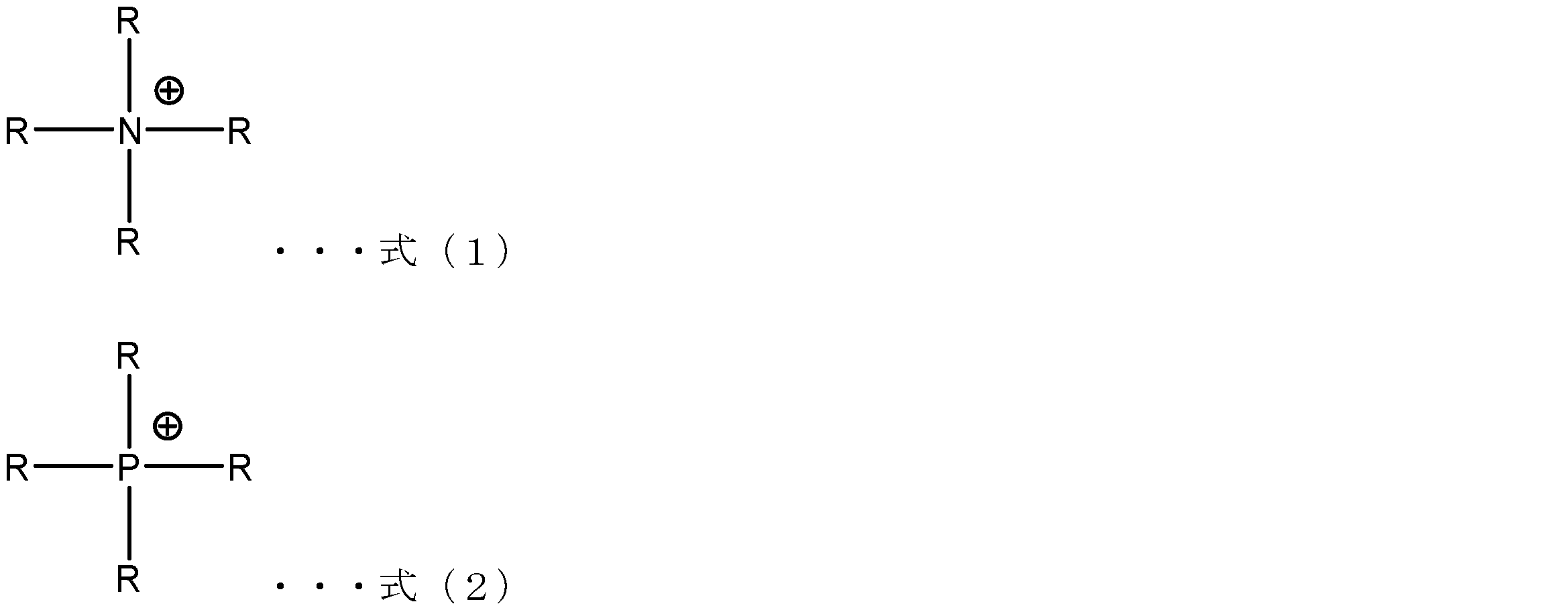
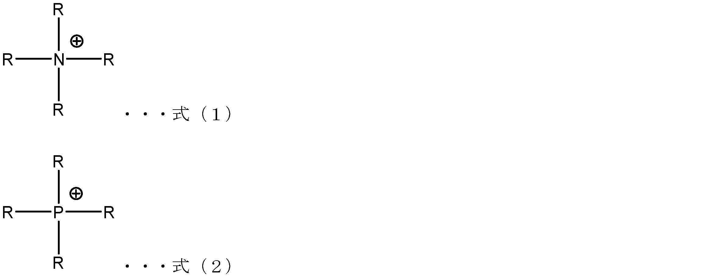
- the present invention is a CO 2 permselective membrane having an ionic liquid containing a cation and an anion and a porous membrane impregnated with the ionic liquid, wherein the cation is represented by the following formula (1).
- a CO 2 permselective membrane comprising at least one selected from the group consisting of ammonium and phosphonium represented by the following formula (2).
- each R independently represents an amino group, a C 1 -C 3 alkyl group optionally substituted with a fluorine atom, or a C 2 optionally substituted with a fluorine atom.
- the above-mentioned CO 2 permselective membrane has a sufficiently high CO 2 permeation rate and / or CO 2 / N 2 selectivity even in a wider range of temperature conditions and relative humidity conditions than the conventional facilitated transport membrane. Can be achieved.
- the anion may include a carboxylate anion.
- a CO 2 permselective membrane having a more excellent CO 2 permeation rate and / or CO 2 / N 2 selectivity can be provided.
- each R may be the amino group.
- the saturated absorption of CO 2 can be increased, and as a result, CO having a better CO 2 permeation rate and / or CO 2 / N 2 selectivity.
- a two permselective membrane can be provided.
- the present invention also relates to a CO 2 selective permeation membrane as described above, by passing the CO 2 in the mixed gas containing CO 2, the CO 2 comprising the step of separating from the mixed gas, a mixed gas of CO 2
- a method of separating from Since this method employs a CO 2 permselective membrane as described above, CO 2 can be mixed stably and effectively over a wider range of temperature and relative humidity conditions than in the prior art. It can be separated from the gas.
- a sufficiently high CO 2 permeation rate and / or CO 2 / N 2 selectivity can be achieved even in a wider range of temperature conditions and relative humidity conditions than in the prior art.
- a CO 2 permselective membrane can be provided.
- the present invention can also provide a method for stably and effectively separating CO 2 from a mixed gas by using the above-mentioned CO 2 permselective membrane.
- CO 2 is a graph showing the relationship between the CO 2 / N 2 selectivity and the temperature of the permselective membrane. It is a graph showing the relationship between the CO 2 permeability and temperature CO 2 selectively permeable membrane. Is a graph showing the relationship between the N 2 permeability and temperature CO 2 selectively permeable membrane.
- CO 2 is a graph showing the relationship between the CO 2 / N 2 selectivity and the temperature of the permselective membrane.
- CO 2 is a graph showing the relationship between the CO 2 permeability and relative humidity of the CO 2 selective permeation membrane. Is a graph showing the relationship between the N 2 permeability and relative humidity of the CO 2 selective permeation membrane.
- CO 2 is a graph showing the relationship between the CO 2 / N 2 selectivity and relative humidity of the permselective membrane.
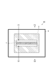
- FIG. 1 is a schematic view showing an embodiment of a membrane separation apparatus having a CO 2 permselective membrane.
- Membrane separation apparatus 10 shown in FIG. 1 is mainly composed of a CO 2 selective permeation membrane 1, and the permeation cell 3 that accommodates the CO 2 selective permeation membrane 1, the heating unit 5 for heating the CO 2 selective permeation membrane 1 .
- a space in which the CO 2 selective permeable membrane 1 is mounted is provided inside the permeation cell 3, and this space is divided by the CO 2 selective permeable membrane 1 into a feed side portion and a sweep side portion.
- a feed gas (mixed gas) F1 containing CO 2 is supplied to the feed side portion and discharged as a feed gas F2.
- the sweep gas S1 is normally supplied to the sweep side portion.
- the sweep gas S1 is generally an inert gas such as helium gas.
- CO 2 selectively permeable membrane 1 selectively permeable to CO 2 which has moved to the sweep side portion gas is discharged together with the sweep gas as a discharge gas S2. As a result, CO 2 is separated from the feed gas F1.
- the CO 2 permselective membrane according to this embodiment includes an ionic liquid containing a cation and an anion, and a porous membrane impregnated with the ionic liquid.
- the cation includes at least one selected from the group consisting of ammonium represented by the following formula (1) and phosphonium represented by the following formula (2).
- each R independently represents an amino group, a C 1 -C 3 alkyl group optionally substituted with a fluorine atom, or a C 2- optionally substituted with a fluorine atom.
- the combination of the anion and the cation is arbitrarily selected as a combination that forms an ionic liquid.
- the ionic liquid may contain a small amount of moisture.
- the water concentration of the ionic liquid may be, for example, 0 to 50% by mass or 5 to 10% by mass.
- an anion in particular is not restrict
- the arbitrary thing which can form an ionic liquid with a counter cation can be selected suitably.
- Such anions may include, for example, carboxylate anions.
- the anion includes a primary amino group (—NH 2 ), a secondary amino group (—NH—), and It may have one or more amino groups selected from tertiary amino groups (—N ⁇ ).
- the said anion may contain the carboxylate anion which has said amino group.
- Such anions include, for example, arginine, histidine, lysine, aspartic acid, glutamic acid, serine, threonine, asparagine, glutamine, cysteine, glycine, proline, alanine, isoleucine, leucine, methionine, phenylalanine, tryptophan, tyrosine, and valine.
- the anion can include N-alkyl amino acids and N-aryl amino acids having secondary amino groups, N, N-dialkyl amino acids and N-alkyl-N-aryl amino acids having tertiary amino groups.
- it may be an anion formed from at least one amino acid selected from glycine and proline.
- the cation is at least one selected from the group consisting of ammonium represented by the above formula (1) and phosphonium represented by the above formula (2).
- each R independently represents an amino group, a C 1 -C 3 alkyl group optionally substituted with a fluorine atom, a C 2 -C 3 alkenyl group optionally substituted with a fluorine atom, Or a C 2 -C 3 alkynyl group optionally substituted with a fluorine atom, wherein the amino group is one or two C 1 -C 3 alkyl groups, a C 2 -C 3 alkenyl group, or C 2 It may be substituted with a —C 3 alkynyl group.
- R may be a C 1 -C 3 alkyl group, and may be a methyl group or an ethyl group.
- each R independently represents an amino group, a C 1 -C 3 alkyl group optionally substituted with a fluorine atom, a C 2 -C 3 alkenyl group optionally substituted with a fluorine atom, Or a C 2 -C 3 alkynyl group optionally substituted with a fluorine atom, wherein the amino group is one or two C 1 -C 3 alkyl groups, a C 2 -C 3 alkenyl group, or C 2 It may be substituted with a —C 3 alkynyl group.
- R may be a C 1 -C 3 alkyl group, and may be a methyl group or an ethyl group.
- each R may be the amino group.
- the cation is, by having an amino group, for amino group and CO 2 in the molecule is reacted with CO 2 is absorbed, resulting in CO 2 permeation rate, and CO 2 / N 2 to more increase the selectivity Can do.
- ammonium or phosphonium include 1,1,1-trimethylhydrazinium, aminotrimethylphosphonium and the like.
- the porous membrane can be appropriately selected from those normally used as a support membrane for a selectively permeable membrane.
- the porous membrane may be hydrophilic or hydrophobic, but may be hydrophilic when the ionic liquid is hydrophilic.
- the porous membrane includes, for example, polytetrafluoroethylene.
- the thickness of the porous film is not particularly limited, but is, for example, 10 to 100 ⁇ m.
- the voids in the porous membrane may be sufficiently filled with the ionic liquid, or may be partially unfilled.
- the porous membrane may be impregnated with a material other than the ionic liquid, if necessary, in addition to the ionic liquid. The type and amount of this additional material can be arbitrarily selected without departing from the spirit of the present invention.
- the CO 2 permselective membrane can be produced by a method including a step of impregnating a porous membrane with an ionic liquid. Impregnation can be performed by a method usually used in the art.
- the feed gas (mixed gas) F1 that passes through the membrane separator 10 and the CO 2 permselective membrane This temperature can be appropriately set experimentally by those skilled in the art, and a sufficiently high CO 2 permeation rate and / or CO 2 / N 2 selectivity can be achieved even in a wide range of temperature conditions.
- As an upper limit of temperature conditions 150 degrees C or less may be sufficient, and 110 degrees C or less may be sufficient.
- 10 degreeC or more may be sufficient and 80 degreeC or more may be sufficient.
- the specific temperature is, for example, 10 to 150 ° C., and may be 80 to 110 ° C.
- the CO 2 permselective membrane 1 is heated by the heating unit 5 as necessary.
- the heating unit 5 for example, an oven capable of accommodating the transmission cell 3 is used.
- the feed gas F1 often contains N 2 in addition to CO 2 .
- the CO 2 permselective membrane according to the present embodiment maintains a high CO 2 permeation rate and / or CO 2 / N 2 selectivity even when the CO 2 partial pressure is low.
- CO 2 selectively permeable film according to the present embodiment is particularly useful.
- the CO 2 partial pressure in the feed gas tends to decrease. Therefore, practically even, in many cases, may include the step of separating CO 2 from a gas mixture of low partial pressure of CO 2 is assumed.
- the CO 2 partial pressure of the feed gas (mixed gas) F1 may be 15 kPa or less.
- the CO 2 permselective membrane according to the present embodiment has a sufficiently high CO 2 permeation rate and / or CO 2 / N even under a wider range of humidity conditions than the conventional facilitated transport membrane. Two selectivity can be achieved.
- the facilitated transport membrane when separating CO 2 gas from a low-humidity mixed gas, it is often necessary to add water vapor to the mixed gas, but according to this embodiment, it is not necessary to add water vapor. , CO 2 can be separated efficiently. Since enormous energy is required to supply water vapor, the necessity of water vapor is very significant in terms of environment and economy.
- the relative humidity of the feed gas (mixed gas) F1 may be less than 50%, 30% or less, and 5% or less.
- the lower limit of the relative humidity is not particularly limited, but may be 0% or more, for example.
- the water vapor concentration of the feed gas (mixed gas) F1 may be less than 30 mol% and 5 mol% or less.
- the lower limit of the water vapor concentration is not particularly limited, but may be, for example, 0 mol% or more.
- the flow rate of the feed gas F1 is not particularly limited, but is, for example, 2 to 1000 mL / min per 10 cm 2 area of the CO 2 permselective membrane.
- the pressure of the feed gas is not particularly limited, but may be atmospheric pressure, and may be adjusted, for example, in the range of 100 to 10000 kPa or 100 to 1000 kPa.
- the flow rate of the sweep gas S1 is not particularly limited, and is, for example, 1 to 500 mL / min per 10 cm 2 area of the CO 2 permselective membrane.
- the pressure of the sweep gas is not particularly limited, but may be atmospheric pressure or less than atmospheric pressure, and may be adjusted to a range of 30 to 5000 kPa or 30 to 1000 kPa, for example. When the partial pressure of CO 2 in the feed gas is sufficiently high, the sweep gas may not necessarily flow.
- an arbitrary layer may be laminated on one side or both sides of the CO 2 permselective membrane.
- Example 1 Tetramethylammonium glycine (hereinafter referred to as [N1111] [Gly]) was prepared as an ionic liquid.
- the ionic liquid was synthesized by a neutralization method. That is, while cooling an aqueous solution containing 40% by mass of tetramethylammonium hydroxide (hereinafter referred to as [N1111] [OH]) to 8 ° C. in a nitrogen atmosphere, an amount of 5% excess of the number of moles thereof is achieved.
- the solution was added dropwise to an aqueous glycine solution containing glycine and 100 mL of pure water. Then, the neutralization reaction of the hydroxide ion and the hydrogen ion derived from glycine was performed by stirring for 24 hours or more. After the neutralization reaction, water was removed at 40 ° C. by an evaporator.
- ionic liquid was removed until the prepared ionic liquid became a 90 mass% aqueous solution (water concentration 10 mass%).
- a porous polytetrafluoroethylene (PTFE) porous membrane (thickness 35.7 ⁇ m, average pore diameter 0.2 ⁇ m) is immersed in the ionic liquid thus prepared, and the pressure is reduced in that state for 1800 seconds to obtain porous.
- the membrane was impregnated with ionic liquid.
- the porous membrane impregnated with the ionic liquid was taken out, and the excess ionic liquid adhering to the surface was removed to obtain a permeable membrane for evaluation.
- Test Example 1 Each prepared permeable membrane was attached to a stainless steel permeation cell. This permeation cell was accommodated in an oven equipped with a thermostat to prepare an evaluation apparatus having the same configuration as the apparatus shown in FIG. The oven was adjusted to a predetermined temperature with a thermostat.
- a dry mixed gas (CO 2 partial pressure: 1.0 kPa) containing CO 2 gas and N 2 gas and substantially free of moisture was used.
- the feed gas F1 was adjusted to a flow rate of 200 mL / min and a temperature of 25 ° C. The pressure on the feed side was maintained at atmospheric pressure.
- Helium gas was used as the sweep gas S1.
- the sweep gas S1 was adjusted to a flow rate of 40 mL / min and a temperature of 25 ° C. The pressure on the sweep side was maintained at atmospheric pressure.
- the outlet side sweep gas (exhaust gas) S2 was analyzed by gas chromatography (GC). From the GC analysis results, CO 2 and N 2 permeation rates and CO 2 / N 2 selectivity were calculated.
- Example 1 and Comparative Examples 1 to 3 For the permeable membranes obtained in Example 1 and Comparative Examples 1 to 3, the CO 2 permeation rate and the N 2 permeation rate when the oven humidity was set to 50 RH% and the set temperature was changed from 30 to 100 ° C., respectively. 2 and 3 show the CO 2 / N 2 selectivity in FIG. 4, respectively.
- the permeation speed is shown as “permeability”. Permeability is expressed as the amount of gas that has passed through a membrane having a unit surface area and unit thickness when a unit pressure drop is applied at a predetermined temperature. The unit of permeability is expressed as “barrer”, and one barrer is 10 ⁇ 10 [cm 3 ⁇ cm 2 / cm 2 ⁇ cmHg ⁇ s]. In calculating the permeation speed, the thickness of the porous film (35.7 ⁇ m) was used as the film thickness. The same applies to FIGS.
- the N 2 permeation rate of the permeable membrane of Example 1 was smaller than that of Comparative Examples 1 to 3. This is thought to be because the free volume of the ionic liquid itself was reduced by selecting a cation having a molecular size as small as possible as the constituent molecule of the ionic liquid, thereby reducing the amount of N 2 dissolved in the ionic liquid. . This tendency was particularly noticeable in the high temperature region.
- Example 2 As an ionic liquid, 1-aminotrimethylammonium glycine (hereinafter referred to as [aN111] [Gly]) was prepared.
- the ionic liquid was synthesized by a neutralization method. That is, 16.1630 g of commercially available 1,1,1-trimethylhydrazinium iodide (hereinafter referred to as [aN111] [I]) is dissolved in 200 mL of pure water, and 12 times the weight of [I] is obtained. so as to OH - added type ion exchange resin, was allowed to proceed stirred to anion exchange reaction for 10 minutes. The [I] concentration in the solution after the reaction was 50 mg / L.
- the ion exchange resin was removed from the reaction solution by filtration, and the reaction solution was added dropwise to an aqueous glycine solution containing 5% excess glycine and 100 mL of pure water than the [aN111] [I] concentration in the solution.
- water was removed at 60 ° C. using an evaporator.
- 50 mL of ethanol was added to precipitate unreacted glycine, the glycine was removed by filtration, and the solvent was removed at 60 ° C. by an evaporator.
- the PTFE porous membrane was impregnated with [aN111] [Gly] thus obtained in the same manner as in Example 1 to obtain a permeable membrane for evaluation.
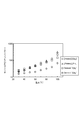
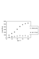
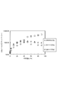
- Test Example 2 The permeable membrane obtained in Example 2 was subjected to the same test as in Test Example 1, and the results are shown in FIGS. 5 to 7 also show the results of Comparative Example 1.
- the permeable membrane of Example 2 has a higher CO 2 permeation rate in addition to the lower N 2 permeation rate than the permeable membrane of Comparative Example 1. became. This is presumably because the CO 2 saturation absorption increased by selecting a cation having an amino group as a constituent molecule of the ionic liquid.
- Test Example 3 An evaluation apparatus was prepared in the same manner as in Test Example 1.
- the CO 2 permeation rate of the permeable membrane of Example 2 was larger than the permeable membrane of Comparative Example 1, and the same result as in Test Example 2 was obtained. This tendency was particularly noticeable in a high humidity region of 50% or more.
- the permeable membrane of Example 2 has extremely excellent CO 2 / N 2 selectivity as compared with the permeable membrane of Comparative Example 1. It turns out to have.
- the CO 2 permeation rate of the permeable membrane is remarkably improved, and as a result, CO 2 having extremely excellent CO 2 / N 2 selectivity.
- a selectively permeable membrane can be provided.
- the permeation membrane has sufficient effects even under a wide range of temperature conditions and relative humidity conditions (particularly under low humidity conditions).
- a sufficiently high CO 2 permeation rate and / or CO 2 / N 2 selectivity can be achieved even in a wider range of temperature conditions and relative humidity conditions than in the prior art.
- a CO 2 permselective membrane can be provided.
- the present invention can also provide a method for stably and effectively separating CO 2 from a mixed gas by using the above-mentioned CO 2 permselective membrane.
Landscapes
- Chemical & Material Sciences (AREA)
- Chemical Kinetics & Catalysis (AREA)
- Organic Chemistry (AREA)
- Engineering & Computer Science (AREA)
- Analytical Chemistry (AREA)
- General Chemical & Material Sciences (AREA)
- Oil, Petroleum & Natural Gas (AREA)
- Water Supply & Treatment (AREA)
- Dispersion Chemistry (AREA)
- Separation Using Semi-Permeable Membranes (AREA)
- Organic Low-Molecular-Weight Compounds And Preparation Thereof (AREA)
Abstract
Description
イオン液体として、テトラメチルアンモニウムグリシン(以下、[N1111][Gly]という。)を準備した。
実施例1と同様の方法により、イオン液体として、テトラブチルアンモニウムグリシン(以下、[N4444][Gly]という。)を準備し、これをPTFE多孔質膜に含浸させて、比較用の透過膜を得た。
実施例1と同様の方法により、イオン液体として、テトラブチルホスホニウムグリシン(以下、[P4444][Gly]という。)を準備し、これをPTFE多孔質膜に含浸させて、比較用の透過膜を得た。
実施例1と同様の方法により、イオン液体として、テトラブチルホスホニウムプロリン(以下、[P4444][Pro]という。)を準備し、これをPTFE多孔質膜に含浸させて、比較用の透過膜を得た。
準備した各透過膜をステンレススチール製の透過セルに装着した。この透過セルをサーモスタットが取り付けられたオーブン内に収容して、図1に示す装置と同様の構成を有する評価装置を準備した。サーモスタットにより、オーブンを所定の温度に調整した。
イオン液体として、1-アミノトリメチルアンモニウムグリシン(以下、[aN111][Gly]という。)を準備した。
実施例2で得た透過膜について、試験例1と同様の試験を行った結果を図5~7にそれぞれ示す。なお、図5~7には、比較例1の結果も併せて示した。
試験例1と同様の方法で評価装置を準備した。
Claims (4)
- カチオン及びアニオンを含有するイオン液体と、該イオン液体が含浸している多孔質膜とを有するCO2選択透過膜であって、
前記カチオンが、下記式(1)で表されるアンモニウム及び下記式(2)で表されるホスホニウムからなる群から選ばれる少なくとも1種を含む、CO2選択透過膜。

- 前記アニオンが、カルボキシレートアニオンを含む、請求項1に記載のCO2選択透過膜。
- 前記式(1)及び(2)において、各Rのうち少なくとも1つが前記アミノ基である、請求項1又は2に記載のCO2選択透過膜。
- 請求項1~3のいずれか一項に記載のCO2選択透過膜に、CO2を含む混合ガス中のCO2を透過させることにより、CO2を前記混合ガスから分離する工程を備える、CO2を混合ガスから分離する方法。
Priority Applications (1)
| Application Number | Priority Date | Filing Date | Title |
|---|---|---|---|
| JP2015530953A JP6431481B2 (ja) | 2013-08-07 | 2014-08-07 | Co2選択透過膜及びco2を混合ガスから分離する方法 |
Applications Claiming Priority (2)
| Application Number | Priority Date | Filing Date | Title |
|---|---|---|---|
| JP2013-164391 | 2013-08-07 | ||
| JP2013164391 | 2013-08-07 |
Publications (1)
| Publication Number | Publication Date |
|---|---|
| WO2015020144A1 true WO2015020144A1 (ja) | 2015-02-12 |
Family
ID=52461473
Family Applications (1)
| Application Number | Title | Priority Date | Filing Date |
|---|---|---|---|
| PCT/JP2014/070855 Ceased WO2015020144A1 (ja) | 2013-08-07 | 2014-08-07 | Co2選択透過膜及びco2を混合ガスから分離する方法 |
Country Status (2)
| Country | Link |
|---|---|
| JP (1) | JP6431481B2 (ja) |
| WO (1) | WO2015020144A1 (ja) |
Cited By (5)
| Publication number | Priority date | Publication date | Assignee | Title |
|---|---|---|---|---|
| CN105148737A (zh) * | 2015-08-14 | 2015-12-16 | 厦门市科宁沃特水处理科技股份有限公司 | 一种基于离子液体聚合的电渗析膜的制备方法 |
| CN105727694A (zh) * | 2016-04-07 | 2016-07-06 | 浙江大学 | 一种利用空间协同效应提高氨基功能化碳捕集的方法 |
| JP2017507771A (ja) * | 2013-12-19 | 2017-03-23 | シー−キャプチャー リミテッドC−Capture Ltd | 酸性ガス回収および放出システム |
| CN111467933A (zh) * | 2019-01-23 | 2020-07-31 | 中国科学院过程工程研究所 | 一种多位点质子型离子液体复合膜选择性分离氨气的方法 |
| JPWO2019130470A1 (ja) * | 2017-12-27 | 2020-12-10 | 株式会社ルネッサンス・エナジー・リサーチ | Co2除去方法及び装置 |
Citations (6)
| Publication number | Priority date | Publication date | Assignee | Title |
|---|---|---|---|---|
| JP2005521750A (ja) * | 2002-04-05 | 2005-07-21 | ユニバーシティ オブ サウス アラバマ | 官能化されたイオン性液体およびこの使用方法 |
| JP2006036950A (ja) * | 2004-07-28 | 2006-02-09 | Mitsubishi Materials Corp | ガスを精製する方法及びその精製に用いられる吸収液 |
| JP2010214324A (ja) * | 2009-03-18 | 2010-09-30 | Petroleum Energy Center | 炭酸ガス分離膜 |
| WO2010149669A1 (en) * | 2009-06-25 | 2010-12-29 | Ae&E Austria Gmbh & Co Kg | Method for sorption of co2 out of flue gas |
| WO2011114168A1 (en) * | 2010-03-19 | 2011-09-22 | The Queen's University Of Belfast | Removal of carbon dioxide from a gas stream by using aqueous ionic liquid |
| JP2012210600A (ja) * | 2011-03-31 | 2012-11-01 | Jx Nippon Oil & Energy Corp | 気体分離装置 |
-
2014
- 2014-08-07 JP JP2015530953A patent/JP6431481B2/ja active Active
- 2014-08-07 WO PCT/JP2014/070855 patent/WO2015020144A1/ja not_active Ceased
Patent Citations (6)
| Publication number | Priority date | Publication date | Assignee | Title |
|---|---|---|---|---|
| JP2005521750A (ja) * | 2002-04-05 | 2005-07-21 | ユニバーシティ オブ サウス アラバマ | 官能化されたイオン性液体およびこの使用方法 |
| JP2006036950A (ja) * | 2004-07-28 | 2006-02-09 | Mitsubishi Materials Corp | ガスを精製する方法及びその精製に用いられる吸収液 |
| JP2010214324A (ja) * | 2009-03-18 | 2010-09-30 | Petroleum Energy Center | 炭酸ガス分離膜 |
| WO2010149669A1 (en) * | 2009-06-25 | 2010-12-29 | Ae&E Austria Gmbh & Co Kg | Method for sorption of co2 out of flue gas |
| WO2011114168A1 (en) * | 2010-03-19 | 2011-09-22 | The Queen's University Of Belfast | Removal of carbon dioxide from a gas stream by using aqueous ionic liquid |
| JP2012210600A (ja) * | 2011-03-31 | 2012-11-01 | Jx Nippon Oil & Energy Corp | 気体分離装置 |
Cited By (7)
| Publication number | Priority date | Publication date | Assignee | Title |
|---|---|---|---|---|
| JP2017507771A (ja) * | 2013-12-19 | 2017-03-23 | シー−キャプチャー リミテッドC−Capture Ltd | 酸性ガス回収および放出システム |
| CN105148737A (zh) * | 2015-08-14 | 2015-12-16 | 厦门市科宁沃特水处理科技股份有限公司 | 一种基于离子液体聚合的电渗析膜的制备方法 |
| CN105148737B (zh) * | 2015-08-14 | 2016-05-25 | 厦门市科宁沃特水处理科技股份有限公司 | 一种基于离子液体聚合的电渗析膜的制备方法 |
| CN105727694A (zh) * | 2016-04-07 | 2016-07-06 | 浙江大学 | 一种利用空间协同效应提高氨基功能化碳捕集的方法 |
| CN105727694B (zh) * | 2016-04-07 | 2018-05-29 | 浙江大学 | 一种利用空间协同效应提高氨基功能化碳捕集的方法 |
| JPWO2019130470A1 (ja) * | 2017-12-27 | 2020-12-10 | 株式会社ルネッサンス・エナジー・リサーチ | Co2除去方法及び装置 |
| CN111467933A (zh) * | 2019-01-23 | 2020-07-31 | 中国科学院过程工程研究所 | 一种多位点质子型离子液体复合膜选择性分离氨气的方法 |
Also Published As
| Publication number | Publication date |
|---|---|
| JPWO2015020144A1 (ja) | 2017-03-02 |
| JP6431481B2 (ja) | 2018-11-28 |
Similar Documents
| Publication | Publication Date | Title |
|---|---|---|
| JP6245607B2 (ja) | Co2選択透過膜、co2を混合ガスから分離する方法、及び膜分離装置 | |
| US9597632B2 (en) | Selectively CO 2-permeable membrane, method for separating CO2 from mixed gas, and membrane separation equipment | |
| Swati et al. | Protic/aprotic ionic liquids for effective CO2 separation using supported ionic liquid membrane | |
| JP6431481B2 (ja) | Co2選択透過膜及びco2を混合ガスから分離する方法 | |
| Gao et al. | Functionalized ionic liquid membranes for CO 2 separation | |
| US11772052B2 (en) | Membranes for gas separation | |
| US6635103B2 (en) | Membrane separation of carbon dioxide | |
| Kamio et al. | Hollow fiber-type facilitated transport membrane composed of a polymerized ionic liquid-based gel layer with amino acidate as the CO2 carrier | |
| US11338242B2 (en) | Method and apparatus for removing CO2 | |
| Chen et al. | Selective CO2 Separation from CO2− N2 Mixtures by Immobilized Glycine-Na− Glycerol Membranes | |
| Duan et al. | Separation of propylene/propane mixture by a supported liquid membrane containing triethylene glycol and a silver salt | |
| Matsumoto et al. | Vapor permeation of hydrocarbons through supported liquid membranes based on ionic liquids | |
| EP3506994B1 (en) | Combined acidic gas capture and water extraction process | |
| Atlaskin et al. | Evaluation of the absorbing pervaporation technique for ammonia recovery after the Haber process | |
| EP1740291A1 (en) | Membrane for separating co2 and process for the production thereof | |
| JP5904479B2 (ja) | ガス分離膜 | |
| Blinova et al. | Functionalized high performance polymer membranes for separation of carbon dioxide and methane | |
| JP7120523B2 (ja) | 水処理分離膜の製造方法およびこれにより製造された水処理分離膜 | |
| KR102238290B1 (ko) | 역삼투막, 이를 포함하는 수처리 모듈 및 이의 제조방법 | |
| JP5877961B2 (ja) | 気体分離ゲル膜 | |
| Kamiya et al. | CO2 separation from air by nanoparticle-supported liquid membranes of amine and ionic liquid mixtures | |
| US20250032990A1 (en) | Membrane contactor for energy-efficient co2 capture from point sources with physical solvents | |
| US20260014528A1 (en) | Ordered Metal Organic Framework Polymer Membranes | |
| Crespo et al. | Ionic liquid membrane technology | |
| Van Eygen et al. | Effects of silica nanoparticle addition and PDMS coating on membrane performance and stability in the extraction of aromatic amines |
Legal Events
| Date | Code | Title | Description |
|---|---|---|---|
| 121 | Ep: the epo has been informed by wipo that ep was designated in this application |
Ref document number: 14834494 Country of ref document: EP Kind code of ref document: A1 |
|
| ENP | Entry into the national phase |
Ref document number: 2015530953 Country of ref document: JP Kind code of ref document: A |
|
| NENP | Non-entry into the national phase |
Ref country code: DE |
|
| 32PN | Ep: public notification in the ep bulletin as address of the adressee cannot be established |
Free format text: NOTING OF LOSS OF RIGHTS PURSUANT TO RULE 112(1) EPC (EPO FORM 1205A DATED 23/05/2016) |
|
| 122 | Ep: pct application non-entry in european phase |
Ref document number: 14834494 Country of ref document: EP Kind code of ref document: A1 |