WO2015019800A1 - 貼着型制振材 - Google Patents
貼着型制振材 Download PDFInfo
- Publication number
- WO2015019800A1 WO2015019800A1 PCT/JP2014/068682 JP2014068682W WO2015019800A1 WO 2015019800 A1 WO2015019800 A1 WO 2015019800A1 JP 2014068682 W JP2014068682 W JP 2014068682W WO 2015019800 A1 WO2015019800 A1 WO 2015019800A1
- Authority
- WO
- WIPO (PCT)
- Prior art keywords
- damping
- layer
- damping material
- vibration
- sticking type
- Prior art date
- Legal status (The legal status is an assumption and is not a legal conclusion. Google has not performed a legal analysis and makes no representation as to the accuracy of the status listed.)
- Ceased
Links
Images
Classifications
-
- F—MECHANICAL ENGINEERING; LIGHTING; HEATING; WEAPONS; BLASTING
- F16—ENGINEERING ELEMENTS AND UNITS; GENERAL MEASURES FOR PRODUCING AND MAINTAINING EFFECTIVE FUNCTIONING OF MACHINES OR INSTALLATIONS; THERMAL INSULATION IN GENERAL
- F16F—SPRINGS; SHOCK-ABSORBERS; MEANS FOR DAMPING VIBRATION
- F16F9/00—Springs, vibration-dampers, shock-absorbers, or similarly-constructed movement-dampers using a fluid or the equivalent as damping medium
- F16F9/30—Springs, vibration-dampers, shock-absorbers, or similarly-constructed movement-dampers using a fluid or the equivalent as damping medium with solid or semi-solid material, e.g. pasty masses, as damping medium
- F16F9/306—Springs, vibration-dampers, shock-absorbers, or similarly-constructed movement-dampers using a fluid or the equivalent as damping medium with solid or semi-solid material, e.g. pasty masses, as damping medium of the constrained layer type, i.e. comprising one or more constrained viscoelastic layers
-
- B—PERFORMING OPERATIONS; TRANSPORTING
- B32—LAYERED PRODUCTS
- B32B—LAYERED PRODUCTS, i.e. PRODUCTS BUILT-UP OF STRATA OF FLAT OR NON-FLAT, e.g. CELLULAR OR HONEYCOMB, FORM
- B32B25/00—Layered products comprising a layer of natural or synthetic rubber
- B32B25/02—Layered products comprising a layer of natural or synthetic rubber with fibres or particles being present as additives in the layer
-
- B—PERFORMING OPERATIONS; TRANSPORTING
- B32—LAYERED PRODUCTS
- B32B—LAYERED PRODUCTS, i.e. PRODUCTS BUILT-UP OF STRATA OF FLAT OR NON-FLAT, e.g. CELLULAR OR HONEYCOMB, FORM
- B32B25/00—Layered products comprising a layer of natural or synthetic rubber
- B32B25/04—Layered products comprising a layer of natural or synthetic rubber comprising rubber as the main or only constituent of a layer, which is next to another layer of the same or of a different material
- B32B25/06—Layered products comprising a layer of natural or synthetic rubber comprising rubber as the main or only constituent of a layer, which is next to another layer of the same or of a different material of paper or cardboard
-
- B—PERFORMING OPERATIONS; TRANSPORTING
- B32—LAYERED PRODUCTS
- B32B—LAYERED PRODUCTS, i.e. PRODUCTS BUILT-UP OF STRATA OF FLAT OR NON-FLAT, e.g. CELLULAR OR HONEYCOMB, FORM
- B32B7/00—Layered products characterised by the relation between layers; Layered products characterised by the relative orientation of features between layers, or by the relative values of a measurable parameter between layers, i.e. products comprising layers having different physical, chemical or physicochemical properties; Layered products characterised by the interconnection of layers
- B32B7/04—Interconnection of layers
- B32B7/06—Interconnection of layers permitting easy separation
-
- B—PERFORMING OPERATIONS; TRANSPORTING
- B32—LAYERED PRODUCTS
- B32B—LAYERED PRODUCTS, i.e. PRODUCTS BUILT-UP OF STRATA OF FLAT OR NON-FLAT, e.g. CELLULAR OR HONEYCOMB, FORM
- B32B2264/00—Composition or properties of particles which form a particulate layer or are present as additives
- B32B2264/10—Inorganic particles
- B32B2264/104—Oxysalt, e.g. carbonate, sulfate, phosphate or nitrate particles
-
- B—PERFORMING OPERATIONS; TRANSPORTING
- B32—LAYERED PRODUCTS
- B32B—LAYERED PRODUCTS, i.e. PRODUCTS BUILT-UP OF STRATA OF FLAT OR NON-FLAT, e.g. CELLULAR OR HONEYCOMB, FORM
- B32B2307/00—Properties of the layers or laminate
- B32B2307/20—Properties of the layers or laminate having particular electrical or magnetic properties, e.g. piezoelectric
- B32B2307/202—Conductive
-
- B—PERFORMING OPERATIONS; TRANSPORTING
- B32—LAYERED PRODUCTS
- B32B—LAYERED PRODUCTS, i.e. PRODUCTS BUILT-UP OF STRATA OF FLAT OR NON-FLAT, e.g. CELLULAR OR HONEYCOMB, FORM
- B32B2307/00—Properties of the layers or laminate
- B32B2307/70—Other properties
- B32B2307/748—Releasability
-
- B—PERFORMING OPERATIONS; TRANSPORTING
- B32—LAYERED PRODUCTS
- B32B—LAYERED PRODUCTS, i.e. PRODUCTS BUILT-UP OF STRATA OF FLAT OR NON-FLAT, e.g. CELLULAR OR HONEYCOMB, FORM
- B32B2457/00—Electrical equipment
-
- B—PERFORMING OPERATIONS; TRANSPORTING
- B32—LAYERED PRODUCTS
- B32B—LAYERED PRODUCTS, i.e. PRODUCTS BUILT-UP OF STRATA OF FLAT OR NON-FLAT, e.g. CELLULAR OR HONEYCOMB, FORM
- B32B2509/00—Household appliances
Definitions
- the present invention relates to a sticking type vibration damping material, and more particularly to a sticking type vibration damping material used by sticking to a vibration member used in various industrial products.
- vibration damping sheet to a component (vibrating member).
- a damping sheet has been proposed in which a paperboard is provided on one side of a rubber sheet containing butyl rubber and a pressure-sensitive adhesive layer containing butyl rubber is provided on the other side of the rubber sheet (for example, a patent Reference 1).
- mica is mixed with a rubber-based composition containing rubber as a main component, and the dynamic shear storage elastic modulus is 1.0 ⁇ 10 5 dyn / cm 2 or more and 1.0 ⁇ 10 7 dyn / cm 2 or less.
- a pressure-adhesive vibration damping composition layer has been proposed (see, for example, Patent Document 2).
- the vibration-damping sheet of Patent Document 1 and the pressure-sensitive adhesive vibration damping composition layer of Patent Document 2 are both pressure-sensitive adhesive sheets (or layers) formed from a rubber composition containing rubber as a main component. It is attached to a component (vibrating member) at a high temperature (for example, 40 ° C. or higher).
- An object of the present invention is to provide a sticking type vibration damping material having good vibration damping and heat dissipation.
- the sticking type damping material of the present invention is a sticking type damping material comprising a damping layer and a constraining layer laminated on the damping layer, wherein the damping layer measures dynamic viscoelasticity.
- the apparatus When measured under the measurement conditions of a shear mode, a heating rate of 5 ° C./min, and a frequency of 1 Hz, the apparatus has a tan ⁇ peak of 1.0 or more in the range of ⁇ 20 to 20 ° C.
- the thermal conductivity is 0.40 W / m ⁇ K or more.
- the vibration damping layer contains rubber and at least one particle selected from the group consisting of metal, metal oxide, and metal hydroxide,
- the content ratio of the particles is preferably 50 to 1500 parts by mass with respect to 100 parts by mass of the rubber.
- the constraining layer is a metal having a thermal conductivity of 10 W / m ⁇ K or more.
- the sticking type damping material of the present invention has a peak of a loss factor of 0.05 or more in the range of 20 to 80 ° C. when measured by the center vibration method.
- the thickness is 3.0 mm or less.
- the sticking type damping material of the present invention is a sticking type damping material comprising a damping layer and a constraining layer laminated on the damping layer, and the damping layer is a dynamic viscoelasticity measuring device.
- a peak of tan ⁇ of 1.0 or more is observed in the range of ⁇ 20 to 20 ° C. when measured under the measurement conditions of the shear mode, the heating rate of 5 ° C./min, and the frequency of 1 Hz. Therefore, if the sticking type
- the thermal conductivity of the damping layer is 0.40 W / m ⁇ K or more. Therefore, even if the sticking type vibration damping material of the present invention is stuck to a heat generating vibration member, heat can be radiated to the outside. As a result, thermal damage in the vibrating member can be reduced.
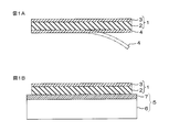
- FIG. 1A and 1B are explanatory views showing a method for adhering one embodiment of the sticking type vibration damping material of the present invention to a vibration member, and FIG. 1A prepares a sticking type vibration damping material, The step of peeling the release paper and FIG. 1B show the step of sticking the sticking type damping material to the vibration member.
- the sticking type damping material 1 includes a damping layer 2 and a constraining layer 3 laminated on the damping layer 2.
- the vibration damping layer 2 is formed into a sheet shape from the heat conductive vibration damping composition.
- the heat conductive vibration damping composition contains, for example, rubber and a filler.
- Examples of rubber include butyl rubber, acrylic rubber, silicone rubber, urethane rubber, vinyl alkyl ether rubber, polyvinyl alcohol rubber, polyvinyl pyrrolidone rubber, polyacrylamide rubber, cellulose rubber, natural rubber, butadiene rubber, chloroprene rubber, and styrene / isoprene rubber.
- Styrene / butadiene rubber acrylonitrile / butadiene rubber, styrene / ethylene / butadiene / styrene rubber, styrene / isoprene / styrene rubber, isoprene rubber, styrene / butadiene / styrene rubber, polyisobutylene, etc. at room temperature (25 ° C.)
- a solid or semi-solid rubber may be mentioned.
- These rubbers may be used alone or in combination.
- butyl rubber is preferable from the viewpoint of adhesion and vibration damping properties.
- Butyl rubber is a synthetic rubber obtained by copolymerization of isobutene (isobutylene) and isoprene.
- the degree of unsaturation of butyl rubber is, for example, 0.8 or more, preferably 1.0 or more, and for example, 2.2 or less, preferably 2.0 or less.
- the Mooney viscosity (ML1 + 8, at 125 ° C.) of the rubber is, for example, 25 or more, preferably 30 or more, and for example, 90 or less, preferably 60 or less.
- the rubber content is, for example, 5% by mass or more, preferably 8% by mass or more, and, for example, less than 50% by mass, preferably 30% by mass or less, with respect to the thermally conductive vibration damping composition. It is.
- Examples of the filler include thermally conductive particles, and preferably at least one kind of particles selected from the group consisting of metals, metal oxides, and metal hydroxides.
- Examples of the metal include aluminum, iron, zinc, nickel, copper, silver, gold, and platinum. From the viewpoint of thermal conductivity, aluminum, iron and zinc are preferable, and from the viewpoint of further weight reduction, aluminum is more preferable.
- metal oxide examples include aluminum oxide (alumina), zinc oxide, iron oxide, titanium oxide (titania), tin oxide, copper oxide, and nickel oxide. From the viewpoint of thermal conductivity, aluminum oxide, zinc oxide, and iron oxide are preferable, and aluminum oxide is more preferable.
- metal hydroxide examples include aluminum hydroxide and magnesium hydroxide.
- These particles can be used alone or in combination of two or more.
- a metal hydroxide alone, a combined use of a metal hydroxide and a metal, a combined use of a metal hydroxide and a metal oxide, particularly at high temperatures.
- vibration damping properties it is more preferable to use a combination of a metal hydroxide and a metal, a combination of a metal hydroxide and a metal oxide, and most preferably a combination of a metal hydroxide and a metal.
- aluminum hydroxide alone combined use of aluminum hydroxide and aluminum, combined use of aluminum hydroxide and aluminum oxide, more preferably combined use of aluminum hydroxide and aluminum, hydroxylated
- aluminum hydroxide and aluminum preferably, aluminum hydroxide alone, combined use of aluminum hydroxide and aluminum, combined use of aluminum hydroxide and aluminum oxide, more preferably combined use of aluminum hydroxide and aluminum, hydroxylated
- aluminum and aluminum oxide most preferably, the combined use of aluminum hydroxide and aluminum.
- the shape of the particles is not particularly limited, and examples thereof include a bulk shape, a needle shape, a plate shape, a layer shape, and a tube shape.
- the particle shape includes a bulk shape, a needle shape, a plate shape, and the like.
- Specific examples of the bulk shape include a spherical shape, a rectangular parallelepiped shape, and a pulverized shape.
- the particle size is not particularly limited, and the average particle diameter is preferably 1/10 or less and 1/1000 or more with respect to the thickness of the damping layer 2. More specifically, for example, it is 0.1 ⁇ m or more, preferably 1 ⁇ m or more, more preferably 2 ⁇ m or more, and for example, 1000 ⁇ m or less, preferably 100 ⁇ m or less, and more preferably 50 ⁇ m or less.
- the average particle diameter of the particles is a volume-based average particle diameter determined by particle size distribution measurement by a laser scattering method. Specifically, the average particle diameter of the thermally conductive particles is determined by measuring the D50 value (median diameter) with a laser scattering particle size distribution meter.
- the particle diameter of the particles By making the particle diameter of the particles not more than the above upper limit value, the moldability from the thermally conductive damping composition to the damping layer 2 (sheet-like) is excellent. Moreover, by setting the particle diameter of the particles to be equal to or more than the lower limit value, the moldability to the damping layer 2 (sheet shape) is excellent, and the thermal conductivity of the damping layer 2 is improved.
- the thermal conductivity of the particles is, for example, 1 W / m ⁇ K or more, preferably 2 W / m ⁇ K or more, more preferably 3 W / m ⁇ K or more, and usually 1000 W / m ⁇ K or less. is there.
- the thermal conductivity of the particles is measured, for example, by a hot wire method (probe method).
- the particles commercially available products can be used.
- examples of such commercially available products include aluminum powder for filler (manufactured by Toyo Aluminum Co., Ltd.) for aluminum particles (powdered aluminum).
- aluminum oxide particles AS-50 (manufactured by Showa Denko) and the like can be mentioned.
- SN series manufactured by Ishihara Sangyo Co., Ltd.
- SN-100S, SN-100P, SN-100D water-dispersed product
- titanium oxide particles examples include TTO series such as TTO-50 and TTO-51 (manufactured by Ishihara Sangyo Co., Ltd.) and ZnO series such as ZnO-310, ZnO-350 and ZnO-410 (manufactured by Sumitomo Osaka Cement Co., Ltd.).
- TTO series such as TTO-50 and TTO-51
- ZnO series such as ZnO-310, ZnO-350 and ZnO-410 (manufactured by Sumitomo Osaka Cement Co., Ltd.).
- the Hijilite series manufactured by Showa Denko
- Hijilite H-10, Hijilite H-32, Hijilite H-42, Hijilite H-100-ME and the like can be mentioned.
- magnesium hydroxide particles KISUMA 5A (manufactured by Kyowa Chemical Industry Co., Ltd.) can be used.
- the content ratio of the particles is, for example, 50 parts by mass or more, preferably 100 parts by mass or more, more preferably 300 parts by mass or more, and 1500 parts by mass or less with respect to 100 parts by mass of rubber. It is 1200 mass parts or less, More preferably, it is 1000 mass parts or less.
- the particle content ratio exceeds the above upper limit, the flexibility of the damping layer 2 may be reduced, and the adhesive force may be reduced.
- the content ratio of the particles is less than the lower limit, the thermal conductivity may not be sufficiently improved.
- a metal or a metal oxide is less than 100 mass parts with respect to 100 mass parts of metal hydroxides, Preferably, 70 mass parts is preferable. For example, it is 10 parts by mass or more, preferably 30 parts by mass or more. Thereby, it is excellent in thermal conductivity and vibration damping.
- the thermally conductive vibration damping composition can contain, for example, a softener, a tackifier, carbon black, an anti-aging agent, and the like.
- the softener is blended in the heat conductive vibration damping composition as necessary from the viewpoint of adjusting the peak position and height of tan ⁇ (described later) of the vibration damping layer 2.
- the softening agent include oils such as paraffinic oil and naphthenic oil, and low molecular weight liquid rubbers such as liquid polybutene, and esters such as phthalic acid esters and phosphoric acid esters.
- These softeners may be used alone or in combination.
- liquid polybutene is preferable.
- the liquid polybutene, kinematic viscosity at 40 ° C. for example, 1000 mm 2 / s or more, preferably is at 10000 mm 2 / s or more, and is, for example, 200000 mm 2 / s or less, preferably below 100,000 mm 2 / s is there.
- the kinematic viscosity at 100 ° C. is, for example, 50 mm 2 / s or more, preferably 100 mm 2 / s or more, and, for example, 4000 mm 2 / s or less, preferably 2000 mm 2 / s or less.
- the content of the softening agent is, for example, 10 parts by mass or more, preferably 50 parts by mass or more, and for example, 200 parts by mass or less, preferably 150 parts by mass or less with respect to 100 parts by mass of rubber. .
- the tackifier is blended in the thermally conductive vibration damping composition as necessary from the viewpoint of adjusting the peak position and height of tan ⁇ (described later) of the vibration damping layer 2.
- the tackifier include rosin resin, terpene resin, coumarone resin, phenol resin, phenol formalin resin, xylene formalin resin, petroleum resin (for example, C5 petroleum resin, C9 petroleum resin, C5 / C9 petroleum resin, etc.).
- tackifiers may be used alone or in combination.
- a petroleum resin is preferable.
- the content of the tackifier is, for example, 10 parts by mass or more, preferably 50 parts by mass or more, and for example, 200 parts by mass or less, preferably 150 parts by mass or less with respect to 100 parts by mass of rubber. is there.
- Carbon black is blended in the heat conductive damping composition as necessary from the viewpoint of the adhesiveness and damping property of the damping layer 2.
- Examples of carbon black include furnace black, acetylene black, ketjen black, channel black, thermal black, and carbon nanotube.
- carbon blacks can be used alone or in combination.
- the shape of carbon black is not particularly limited, and examples thereof include a substantially spherical shape, a substantially needle shape, a substantially plate shape, and a substantially tube shape.
- the average value of the maximum length of carbon black (in the case of a substantially spherical shape, the average particle diameter) is, for example, 60 nm or less, preferably 50 nm or less, more preferably 35 nm or less, for example, 10 nm or more.
- the average value of the maximum length of carbon black is calculated as a volume-based arithmetic average particle diameter obtained by particle size distribution measurement by a laser scattering method.
- the content ratio of carbon black is, for example, 0.5 parts by mass or more, preferably 1 part by mass or more, and for example, 10 parts by mass or less, preferably 5 parts by mass or less with respect to 100 parts by mass of rubber. It is.
- Antiaging agents include, for example, aromatic amines (specifically, aromatic secondary amines such as 4,4′-bis ( ⁇ , ⁇ -dimethylbenzyl) diphenylamine), phenols, and imidazoles. Etc.
- anti-aging agents can be used alone or in combination.
- aromatic amines are preferable.
- the content of the anti-aging agent is, for example, 0.5 parts by mass or more, preferably 1 part by mass or more, and for example, 10 parts by mass or less, preferably 5 parts by mass with respect to 100 parts by mass of rubber. It is as follows.
- the thermally conductive vibration damping composition includes, for example, a crosslinking agent, a crosslinking accelerator, a filler (excluding the particles and carbon black), a foaming agent, a lubricant, a thixotropic agent (for example, montmorillonite), Oils and fats (for example, animal fats and oils, vegetable fats and oils, mineral oils, etc.), pigments, scorch inhibitors, stabilizers, plasticizers, ultraviolet absorbers, antifungal agents and other known additives in appropriate proportions Further, it can be contained.
- a crosslinking agent for example, a crosslinking accelerator, a filler (excluding the particles and carbon black), a foaming agent, a lubricant, a thixotropic agent (for example, montmorillonite), Oils and fats (for example, animal fats and oils, vegetable fats and oils, mineral oils, etc.), pigments, scorch inhibitors, stabilizers, plasticizers, ultraviolet absorbers, antifungal agents and other known additive
- the thermally conductive vibration damping composition is prepared by blending the above-described components in the above-described content ratio, and kneading with a kneader such as a mixing roll, a pressure kneader, a Banbury mixer, an extruder, etc.
- a kneader such as a mixing roll, a pressure kneader, a Banbury mixer, an extruder, etc.
- the obtained kneaded product is stretched by pressing, for example, by calendar molding, extrusion molding, press molding, or the like, thereby forming the damping layer 2 in a sheet shape (that is, forming into a sheet).
- the vibration damping layer 2 is preferably a non-foaming viscoelastic layer and has a surface tack (adhesive force) that can be directly attached to the vibration component 5 (described later).
- the thickness of the damping layer 2 is, for example, 0.5 mm or more, preferably 0.8 mm or more, and 3.0 mm or less, preferably 2.8 mm or less.
- the damping layer 2 has a tan ⁇ peak in the range of ⁇ 20 to 20 ° C. (preferably ⁇ 10 to 10 ° C.).
- the peak of tan ⁇ is 1.0 or more, preferably 1.8 or more, more preferably 2.0 or more, and for example, 4.0 or less.
- tan ⁇ is a storage viscoelastic modulus G ′ and a loss shear elastic modulus G ′ of the damping layer 2 using a dynamic viscoelasticity measuring device under measurement conditions of a shear mode, a heating rate of 5 ° C./min, and a frequency of 1 Hz.
- the loss factor for example, 20
- Loss factor at ⁇ 80 ° C. the damping property of the sticking type damping material 1 is excellent.
- the thermal conductivity of the damping layer 2 is 0.40 W / m ⁇ K or more, preferably 0.60 W / m ⁇ K or more, more preferably 0.80 W / m ⁇ K or more, For example, it is 4.00 W / m ⁇ K or less.
- thermal conductivity is less than the said lower limit, the heat conductivity of the sticking type
- the 90-degree peel adhesive strength of the vibration damping layer 2 at 23 ° C. is, for example, 10 N / 25 mm or more, preferably 20 N / 25 mm or more, preferably 30 N / 25 mm or more.
- 90 degree peeling adhesive force is 90 degree
- the damping layer 2 When the 90-degree peeling adhesive strength of the damping layer 2 is within the above range, the damping layer 2 has sufficient tackiness at room temperature.
- the constraining layer 3 is laminated on the damping layer 2 in order to constrain the damping layer 2 and to impart strength and thermal conductivity to the damping layer 2.
- the constraining layer 3 is in the form of a sheet, is lightweight and thin, and can be tightly integrated with the damping layer 2 and is made of a material having thermal conductivity.
- the thermal conductivity of the constraining layer 3 is, for example, 10 W / m ⁇ K or more, preferably 50 W / m ⁇ K or more, more preferably 100 W / m ⁇ K or more, and for example, 1000 W / m ⁇ K. It is as follows. When the thermal conductivity of the constraining layer 3 is within the above range, the thermal conductivity of the sticking type damping material 1 is excellent, and the loss coefficient of the sticking type damping material 1 can be improved.
- constraining layer 3 examples include metal foil.
- metal foil examples include aluminum foil and steel foil, and aluminum foil is preferable from the viewpoint of thermal conductivity and light weight.
- the thickness of the constraining layer 3 is, for example, 0.05 mm or more, preferably 0.1 mm or more, and 3.0 mm or less, preferably 1.0 mm or less.
- the total thickness of the damping layer 2 and the constraining layer 3 (that is, the thickness of the sticking type damping material 1) is, for example, 3.0 mm or less, preferably 2.8 mm or less, 0.5 mm or more, preferably 0.8 mm or more.
- the damping performance may be low.
- the thickness of the sticking type damping material 1 exceeds the above upper limit value, although the damping property is recognized, the thermal conductivity may be low.
- the damping layer 2 and the constraining layer 3 are stuck by, for example, pressure bonding or thermocompression bonding.
- a known release paper 4 can be stuck on the surface of the damping layer 2 on the side opposite to the layered side of the constraining layer 3, if necessary. In that case, the release paper 4 is laminated on the damping layer 2 when the damping layer 2 is formed into a sheet.
- the sticking type damping material 1 preferably has a loss coefficient peak in the range of 20 to 80 ° C. (especially 20 to 60 ° C.).
- the loss coefficient at the peak is, for example, 0.05 or more, preferably 0.10 or more, more preferably 0.40 or more, particularly preferably 0.48 or more, and most preferably 0.00. It is 49 or more.
- the loss factor of the sticking type damping material 1 is, for example, 0.05 or more, preferably 0.06 or more, more preferably 0.07 or more at 0 ° C.
- the sticking type damping material 1 has a loss factor in the range of 20 to 80 ° C. (particularly 20 to 60 ° C.), for example, 0.05 or more, preferably 0.10 or more, more preferably It is also 0.15 or more.
- the loss factor of the sticking type damping material 1 is, for example, 0.03 or more, preferably 0.05 or more, and more preferably 0.07 or more at 100 ° C.
- the loss factor was determined by cutting the adhesive damping material 1 to a width of 10 mm and a length of 250 mm to produce a sample, and applying the sample to a 0.8 mm ⁇ 10 mm ⁇ 250 mm SPCC steel plate as the adherend. 2 are attached so that they are in contact with each other, and are measured by a center excitation method at a frequency (for example, 500 Hz) calculated from a resonance point using a loss factor measuring device.
- a frequency for example, 500 Hz
- the vibration part 5 is sufficiently damped. be able to.
- the sticking type damping material 1 obtained in this way is stuck to various parts used in the fields of automobiles, railway vehicles, home appliances, office equipment, housing equipment or machine tools, and the various parts are attached. Damping.
- Examples of the various parts include parts used at high temperatures exceeding 40 ° C. (high-temperature parts), for example, parts used at a wide range of temperatures from room temperature (20 ° C.) to high temperatures (eg 100 ° C.). .
- the sticking type damping material 1 when the release paper 4 is stuck on the surface of the damping layer 2, as shown by the phantom line in FIG.
- the release paper 4 is peeled off from the surface of the layer 2, and then, as shown in FIG. 1B, the surface of the damping layer 2 is attached to a vibration component 5 such as a component that is an adherend.
- the sticking type vibration damping material 1 dampens the vibration component 5.
- the vibration damping layer 2 and the vibration component 5 can be attached by, for example, pressure bonding or thermocompression bonding.
- the vibration component 5 is, for example, a component that needs to release heat generated inside to the outside, and includes a heat generating vibration member 6 and a heat dissipation member that discharges heat generated from the heat generation vibration member 6 to the outside. 7.
- Examples of the heat generating vibration member 6 include heat generating parts such as a motor, a heater, and an engine.
- Examples of the heat radiating member 7 include a heat conductive outer plate.
- the sticking type damping material 1 includes a damping layer 2 and a constraining layer 3, and the damping layer 2 has a tan ⁇ of 1.0 or more in the range of ⁇ 20 to 20 ° C. Therefore, if the sticking type damping material 1 is stuck to the vibration component 5, the vibration component 5 can be sufficiently damped.
- the thermal conductivity of the vibration damping layer 2 is 0.40 W / m ⁇ K or more, when the adhesive vibration damping material 1 is attached to the exothermic vibration component 5, the heat is radiated to the outside. can do. As a result, thermal damage in the vibration component 5 can be reduced.
- the sticking type damping material 1 can sufficiently dampen the vibration component 5 while dissipating heat.
- the vibration damping layer 2 of the sticking type damping material 1 is stuck to the heat radiating member 7. It can also be attached.
- the obtained kneaded material was formed into a sheet by press molding and laminated on the surface of the release paper to form a damping layer having a thickness of 1.4 mm.
- a constraining layer made of aluminum foil (thermal conductivity: 236 W / m ⁇ K) having a thickness of 0.1 mm is attached to the surface of the damping layer opposite to the release paper lamination side by pressure bonding. Then, a sticking type damping material having a total thickness of the damping layer and the constraining layer of 1.5 mm was produced. In the evaluation, the release paper was peeled from the damping layer.
- the thermal diffusivity was measured by a thermal diffusivity / thermal conductivity measuring device (trade name “Eye Phase Mobile”, manufactured by Eye Phase Co.), and the heat capacity was measured by a differential scanning calorimeter (DSC). The results are shown in Table 1.
- Vibration control (loss factor)
- the loss factor at 0 ° C., 20 ° C., 40 ° C., 60 ° C., 80 ° C., and 100 ° C. of the sticking type damping material was measured by the central vibration method under the following measurement conditions using a loss factor measuring device. Specifically, the sticking type damping material was cut into a width of 10 mm and a length of 250 mm, a sample was prepared, and the loss factor was measured by sticking the sample to an adherend. The results are shown in Table 1. Substrate: 0.8 mm x 10 mm x 250 mm SPCC steel plate Frequency: 500 Hz (500 Hz is calculated from the resonance point)
- JSR butyl 268 butyl rubber, unsaturation 1.6, Mooney viscosity 51 (ML1 + 8, at 125 ° C.), manufactured by JSR ⁇ Aluminum hydroxide: “Hijilite H32”, Showa Denko, average particle size 0.3-0 .45 ⁇ m Alumina: “Round Alumina”, Showa Denko, average particle size 9 ⁇ m ⁇ Powdered aluminum: “Aluminum powder for filler”, Toyo Aluminum Co., Ltd., center diameter 50 ⁇ m ⁇ Polybutene HV300: Liquid polybutene, softener, kinematic viscosity 26000 mm 2 / s (at 40 ° C.), kinematic viscosity 590 mm 2 / s (at 100 ° C.), manufactured by Nippon Oil Co., Ltd.
- ⁇ Escollet 1202 petroleum resin, tackifier, exon ⁇ Sheet 3H: Furnace Black, arithmetic average particle size 27 nm, HAF-HS grade, manufactured by Tokai Carbon ⁇ Nocrack CD: 4,4′-bis ( ⁇ , ⁇ -dimethylbenzyl) diphenylamine, anti-aging agent, Ouchi Shinsei Chemical Industry Co., Ltd.
- the above invention is provided as an exemplary embodiment of the present invention, but this is merely an example and should not be interpreted in a limited manner. Variations of the present invention that are apparent to one of ordinary skill in the art are within the scope of the following claims.
- the sticking type damping material of the present invention can be applied to various industrial products. Specifically, it is used in the fields of automobiles, railway vehicles, home appliances, office equipment, housing equipment or machine tools. Used by sticking to various parts.
Landscapes
- Engineering & Computer Science (AREA)
- General Engineering & Computer Science (AREA)
- Mechanical Engineering (AREA)
- Laminated Bodies (AREA)
- Compositions Of Macromolecular Compounds (AREA)
- Vibration Prevention Devices (AREA)
Abstract
貼着型制振材は、制振層と、前記制振層に積層される拘束層とを備える貼着型制振材である。制振層は、動的粘弾性測定装置によって、剪断モード、昇温速度5℃/分、周波数1Hzの測定条件で測定したときに、-20~20℃の範囲に1.0以上のtanδのピークを有し、制振層の熱伝導率が、0.40W/m・K以上である。
Description
本発明は、貼着型制振材、詳しくは、各種産業製品に用いられる振動部材に貼着して用いられる貼着型制振材に関する。
従来より、自動車、鉄道車両、家庭電化機器、事務機器、住宅設備または工作機械などの分野に用いられる各種部品は、その運転時に、振動音を生じ易く、そのため、かかる振動音の発生を抑制すべく、例えば、制振シートを部品(振動部材)に貼着することが知られている。
例えば、ブチルゴムを含有するゴムシートの片面に、板紙が設けられ、ゴムシートの他面に、ブチルゴムを含有する感圧型粘着剤層が設けられている制振シートが提案されている(例えば、特許文献1参照。)。
また、ゴムを主成分とするゴム系組成物にマイカを混合し、動的剪断貯蔵弾性率が1.0×10⁵dyn/cm2以上1.0×107dyn/cm2以下である感圧接着性振動減衰組成物層が提案されている(例えば、特許文献2参照。)。
特許文献1の制振シートおよび特許文献2の感圧接着性振動減衰組成物層は、ともに、ゴムを主成分としたゴム組成物から形成される感圧接着性のシート(または層)であり、高温(例えば40℃以上)の部品(振動部材)に貼着される。
しかしながら、ゴムは、一般的に熱伝導性が低く、断熱材としての役割を備えている。そのため、内部に発生する熱を外部に放熱する必要がある発熱性の振動部品に、特許文献1や特許文献2の制振シートを貼着すると、部品内部に発生する熱が制振シートによって外部に放熱されずに部品内部に蓄熱される。その結果、内部部品に熱損傷を与えるという不具合が生じる。
本発明の目的は、制振性および放熱性が良好な貼着型制振材を提供することにある。
本発明の貼着型制振材は、制振層と、前記制振層に積層される拘束層とを備える貼着型制振材であって、前記制振層は、動的粘弾性測定装置によって、剪断モード、昇温速度5℃/分、周波数1Hzの測定条件で測定したときに、-20~20℃の範囲に1.0以上のtanδのピークを有し、前記制振層の熱伝導率が、0.40W/m・K以上であることを特徴としている。
また、本発明の貼着型制振材では、前記制振層は、ゴムと、金属、金属酸化物および金属水酸化物からなる群から選択される少なくとも1種の粒子とを含有し、前記粒子の含有割合が、前記ゴム100質量部に対し、50~1500質量部であることが好適である。
また、本発明の貼着型制振材では、前記拘束層が、熱伝導率が10W/m・K以上の金属であることが好適である。
また、本発明の貼着型制振材では、中央加振法によって測定したときに、20~80℃の範囲に0.05以上の損失係数のピークを有することが好適である。
また、本発明の貼着型制振材では、厚みが3.0mm以下であることが好適である。
本発明の貼着型制振材は、制振層と、前記制振層に積層される拘束層とを備える貼着型制振材であって、制振層は、動的粘弾性測定装置によって、剪断モード、昇温速度5℃/分、周波数1Hzの測定条件で測定したときに、-20~20℃の範囲に1.0以上のtanδのピークを有する。そのため、本発明の貼着型制振材を振動部材に貼着すれば、振動部材を、十分に制振することができる。
また、本発明の貼着型制振材は、制振層の熱伝導率が、0.40W/m・K以上である。そのため、本発明の貼着型制振材を発熱性の振動部材に貼着しても、熱を外部に放熱することができる。その結果、振動部材における熱損傷を低減することができる。
図1Aにおいて、この貼着型制振材1は、制振層2と、制振層2に積層される拘束層3とを備えている。
制振層2は、熱伝導性制振組成物からシート状に形成されている。
熱伝導性制振組成物は、例えば、ゴムと、充填材とを含有する。
ゴムとしては、例えば、ブチルゴム、アクリルゴム、シリコーンゴム、ウレタンゴム、ビニルアルキルエーテルゴム、ポリビニルアルコールゴム、ポリビニルピロリドンゴム、ポリアクリルアミドゴム、セルロースゴム、天然ゴム、ブタジエンゴム、クロロプレンゴム、スチレン・イソプレンゴム、スチレン・ブタジエンゴム、アクリロニトリル・ブタジエンゴム、スチレン・エチレン・ブタジエン・スチレンゴム、スチレン・イソプレン・スチレンゴム、イソプレンゴム、スチレン・ブタジエン・スチレンゴム、ポリイソブチレンなどの高分子量の常温(25℃)で固形状または半固形状のゴムが挙げられる。
これらゴムは、単独で使用してもよく、あるいは、併用することもできる。
これらゴムのなかでも、接着性、制振性の観点から、好ましくは、ブチルゴムが挙げられる。
ブチルゴムは、イソブテン(イソブチレン)とイソプレンとの共重合により得られる合成ゴムである。
ブチルゴムの不飽和度は、例えば、0.8以上、好ましくは、1.0以上であり、また、例えば、2.2以下、好ましくは、2.0以下である。
ゴムのムーニー粘度(ML1+8、at125℃)は、例えば、25以上、好ましくは、30以上であり、また、例えば、90以下、好ましくは、60以下である。
ゴムの含有割合は、熱伝導性制振組成物に対して、例えば、5質量%以上、好ましくは、8質量%以上であり、また、例えば、50質量%未満、好ましくは、30質量%以下である。
充填材としては、例えば、熱伝導性粒子が挙げられ、好ましくは、金属、金属酸化物および金属水酸化物からなる群から選択される少なくとも1種の粒子が挙げられる。
金属としては、例えば、アルミニウム、鉄、亜鉛、ニッケル、銅、銀、金、白金などが挙げられる。熱伝導率の観点から、好ましくは、アルミニウム、鉄、亜鉛、さらに軽量化の観点から、より好ましくは、アルミニウムが挙げられる。
金属酸化物としては、例えば、酸化アルミニウム(アルミナ)、酸化亜鉛、酸化鉄、酸化チタン(チタニア)、酸化スズ、酸化銅、酸化ニッケルなどが挙げられる。熱伝導率の観点から、好ましくは、酸化アルミニウム、酸化亜鉛、酸化鉄が挙げられ、より好ましくは、酸化アルミニウムが挙げられる。
金属水酸化物としては、例えば、水酸化アルミニウム、水酸化マグネシウムが挙げられる。
これら粒子は、単独使用または2種以上併用することができる。
熱伝導性および制振性の観点から、好ましくは、金属水酸化物の単独使用、金属水酸化物と金属との併用、金属水酸化物と金属酸化物との併用が挙げられ、特に高温での制振性の観点から、より好ましくは、金属水酸化物と金属との併用、金属水酸化物と金属酸化物との併用、最も好ましくは、金属水酸化物と金属との併用が挙げられる。
より具体的には、好ましくは、水酸化アルミニウムの単独使用、水酸化アルミニウムとアルミニウムとの併用、水酸化アルミニウムと酸化アルミニウムとの併用、より好ましくは、水酸化アルミニウムとアルミニウムとの併用、水酸化アルミニウムと酸化アルミニウムとの併用、最も好ましくは、水酸化アルミニウムとアルミニウムとの併用が挙げられる。
粒子の形状は、特に限定されず、例えば、バルク形状、針形状、板形状、層状、チューブ形状などが挙げられる。粒子の形状として、好ましくは、バルク形状、針形状、板形状などが挙げられる。バルク形状としては、具体的には、球形状、直方体形状、粉砕状が挙げられる。
粒子のサイズは、特に限定されず、平均粒子径が、好ましくは、制振層2の厚みに対して、10分の1以下であり、また、1000分の1以上である。より具体的には、例えば、0.1μm以上、好ましくは、1μm以上、より好ましくは、2μm以上であり、また、例えば、1000μm以下、好ましくは、100μm以下、さらに好ましくは、50μm以下である。
粒子の平均粒子径は、レーザー散乱法による粒度分布測定により求められる体積基準の平均粒子径である。具体的には、熱伝導性粒子の平均粒子径は、レーザー散乱式粒度分布計によって、D50値(メジアン径)を測定することにより求められる。
粒子の粒子径を上記上限値以下とすることにより、熱伝導性制振組成物から制振層2(シート状)への成形性に優れる。また、粒子の粒子径を上記下限値以上とすることにより、制振層2(シート状)への成形性に優れるとともに、制振層2の熱伝導性が良好となる。
また、粒子の熱伝導率は、例えば、1W/m・K以上、好ましくは、2W/m・K以上、さらに好ましくは、3W/m・K以上であり、通常、1000W/m・K以下である。粒子の熱伝導率は、例えば、熱線法(プローブ法)によって測定される。
粒子は、市販品を用いることができ、そのような市販品として、例えば、アルミニウム粒子(粉末アルミニウム)では、フィラー用アルミニウムパウダー(東洋アルミニウム社製)などが挙げられる。また、例えば、酸化アルミニウム粒子では、AS-50(昭和電工社製)などが挙げられる。例えば、酸化スズ粒子では、SN-100S、SN-100P、SN-100D(水分散品)などのSNシリーズ(石原産業社製)などが挙げられる。酸化チタン粒子では、TTO-50、TTO-51などのTTOシリーズ(石原産業社製)や、ZnO-310、ZnO-350、ZnO-410などのZnOシリーズ(住友大阪セメント社製)などが挙げられる。また、例えば、水酸化アルミニウム粒子では、ハイジライトH-10、ハイジライトH-32、ハイジライトH-42、ハイジライトH-100-MEなどのハイジライトシリーズ(昭和電工社製)などが挙げられる。例えば、水酸化マグネシウム粒子では、KISUMA 5A(協和化学工業社製)などが挙げられる。
粒子の含有割合は、ゴム100質量部に対して、例えば、50質量部以上、好ましくは、100質量部以上、より好ましくは、300質量部以上であり、また、1500質量部以下、好ましくは、1200質量部以下、より好ましくは、1000質量部以下である。
粒子含有割合が上記上限値を超える場合には、制振層2の可撓性が低下して、接着力が低下する場合がある。一方、粒子の含有割合が上記下限値に満たない場合には、熱伝導率を十分に向上させることができない場合がある。
また、金属水酸化物と、金属または金属酸化物とを併用する場合、金属または金属酸化物は、金属水酸化物100質量部に対して、例えば、100質量部未満、好ましくは、70質量部以下であり、また、例えば、10質量部以上、好ましくは、30質量部以上である。これにより、熱伝導性、制振性に優れる。
また、熱伝導性制振組成物は、上記成分に加えて、例えば、軟化剤、粘着付与剤、カーボンブラック、老化防止剤などを含有することができる。
軟化剤は、制振層2のtanδ(後述)のピーク位置および高さを調整する観点から、必要により熱伝導性制振組成物に配合される。軟化剤としては、例えば、パラフィン系オイル、ナフテン系オイルなどのオイル類、例えば、液状ポリブテンなどの低分子量の液状ゴム、例えば、フタル酸エステル、リン酸エステルなどのエステル類などが挙げられる。
これら軟化剤は、単独で使用してもよく、あるいは、併用することもできる。
これら軟化剤のなかでは、好ましくは、液状ポリブテンが挙げられる。
液状ポリブテンでは、その40℃における動粘度が、例えば、1000mm2/s以上、好ましくは、10000mm2/s以上であり、また、例えば、200000mm2/s以下、好ましくは、100000mm2/s以下である。また、その100℃における動粘度は、例えば、50mm2/s以上、好ましくは、100mm2/s以上であり、また、例えば、4000mm2/s以下、好ましくは、2000mm2/s以下である。
軟化剤の含有割合は、ゴム100質量部に対して、例えば、10質量部以上、好ましくは、50質量部以上であり、また、例えば、200質量部以下、好ましくは、150質量部以下である。
粘着付与剤は、制振層2のtanδ(後述)のピーク位置および高さを調整する観点から、必要により熱伝導性制振組成物に配合される。粘着付与剤としては、例えば、ロジン系樹脂、テルペン系樹脂、クマロン系樹脂、フェノール系樹脂、フェノールホルマリン系樹脂、キシレンホルマリン系樹脂、石油系樹脂(例えば、C5系石油樹脂、C9系石油樹脂、C5/C9系石油樹脂など)などが挙げられる。
これら粘着付与剤は、単独で使用してもよく、あるいは、併用することもできる。
これら粘着付与剤のなかでは、好ましくは、石油系樹脂が挙げられる。
粘着付与剤の含有割合は、ゴム100質量部に対して、例えば、10質量部以上、好ましくは、50質量部以上であり、また、例えば、200質量部以下、好ましくは、150質量部以下である。
カーボンブラックは、制振層2の接着性および制振性の観点から、必要により熱伝導性制振組成物に配合される。カーボンブラックとしては、例えば、ファーネスブラック、アセチレンブラック、ケッチェンブラック、チャンネルブラック、サーマルブラック、カーボンナノチューブなどが挙げられる。
これらカーボンブラックは、単独使用あるいは併用することができる。
カーボンブラックの形状は、特に制限されず、例えば、略球形状、略針形状、略板形状、略チューブ形状などが挙げられる。
カーボンブラックの形状は、特に制限されず、例えば、略球形状、略針形状、略板形状、略チューブ形状などが挙げられる。
カーボンブラックの最大長さの平均値(略球形状の場合には、平均粒子径)は、例えば、60nm以下、好ましくは、50nm以下、さらに好ましくは、35nm以下であり、例えば、10nm以上でもある。カーボンブラックの最大長さの平均値は、レーザー散乱法による粒度分布測定により求められる体積基準の算術平均粒子径として算出される。
カーボンブラックの含有割合は、ゴム100質量部に対して、例えば、0.5質量部以上、好ましくは、1質量部以上であり、また、例えば、10質量部以下、好ましくは、5質量部以下である。
老化防止剤としては、例えば、芳香族アミン系(具体的には、4,4´-ビス(α,α-ジメチルベンジル)ジフェニルアミンなどの芳香族第二級アミン系など)、フェノール系、イミダゾール系などが挙げられる。
これら老化防止剤は、単独使用あるいは併用することができる。
これら老化防止剤のなかでは、好ましくは、芳香族アミン系が挙げられる。
老化防止剤の含有割合は、ゴム100質量部に対して、例えば、0.5質量部以上、好ましくは、1質量部以上であり、また、例えば、10質量部以下、好ましくは、5質量部以下である。
熱伝導性制振組成物は、上記成分以外に、例えば、架橋剤、架橋促進剤、充填材(上記粒子およびカーボンブラックを除く)、発泡剤、滑剤、揺変剤(例えば、モンモリロナイトなど)、油脂類(例えば、動物性油脂、植物性油脂、鉱油など)、顔料、スコーチ防止剤、安定剤、可塑剤、紫外線吸収剤、防カビ剤などの公知のその他の添加剤を、適宜の割合でさらに含有することもできる。
そして、熱伝導性制振組成物は、上記した各成分を、上記した含有割合において配合し、例えば、ミキシングロール、加圧式ニーダー、バンバリーミキサー、押出機などの混練機によって混練して、混練物として調製する。
その後、得られた混練物を、例えば、カレンダー成形、押出成形またはプレス成形などによって押圧により延伸することにより、制振層2をシート状に形成する(つまり、シート化する。)。
これによって、制振層2を形成する。
制振層2は、好ましくは、非発泡性の粘弾性層であり、振動部品5(後述)にそのまま貼着できる表面タック(粘着力)を有している。
制振層2の厚さは、例えば、0.5mm以上、好ましくは、0.8mm以上であり、また、3.0mm以下、好ましくは、2.8mm以下である。
制振層2は、-20~20℃(好ましくは、-10~10℃)の範囲において、tanδのピークを有している。tanδのピークは、1.0以上、好ましくは、1.8以上、より好ましくは、2.0以上であり、また、例えば、4.0以下である。
tanδは、動的粘弾性測定装置を用いて、剪断モード、昇温速度5℃/分、周波数1Hzの測定条件にて、制振層2の貯蔵剪断弾性率G´および損失剪断弾性率G´´を測定し、これらの弾性率の比tanδ(=G´´/G´)を求めることにより得られる。
制振層2のtanδのピークの値を上記範囲内とすることにより、その制振層2の一方面に拘束層3を積層させてなる貼着型制振材1の損失係数(例えば、20~80℃における損失係数)を向上させることができ、貼着型制振材1の制振性が優れる。
制振層2の熱伝導率は、0.40W/m・K以上であり、好ましくは、0.60W/m・K以上、より好ましくは、0.80W/m・K以上であり、また、例えば、4.00W/m・K以下である。熱伝導率が上記下限値に満たない場合には、貼着型制振材1の熱伝導性が低下し、振動部品を放熱できないおそれが生じる。
制振層2の23℃における90度剥離粘着力は、例えば、10N/25mm以上、好ましくは、20N/25mm以上、好ましくは、30N/25mm以上である。
なお、90度剥離粘着力は、制振層2を幅25mm、長さ150mmに切断してサンプルを作製し、サンプルをステンレス板に貼着した後、23℃で、ステンレス板に対して90度で速度300mm/分で万能引張試験機を用いてサンプルを剥離することにより、測定される。
制振層2の90度剥離粘着力が上記範囲内である場合には、制振層2は常温で十分な粘着性を有する。
拘束層3は、制振層2を拘束し、制振層2に強度および熱伝導性を付与するために、制振層2に積層されている。拘束層3は、シート状をなし、また、軽量および薄膜で、制振層2と密着一体化でき、熱伝導性を備える材料から形成されている。
拘束層3の熱伝導率は、例えば、10W/m・K以上、好ましくは、50W/m・K以上、より好ましくは、100W/m・K以上であり、また、例えば、1000W/m・K以下である。拘束層3の熱伝導率が上記範囲内である場合には、貼着型制振材1の熱伝導性に優れ、また、貼着型制振材1の損失係数を向上させることができる。
拘束層3は、具体的には、金属箔などが挙げられる。
金属箔としては、例えば、アルミニウム箔、スチール箔などが挙げられ、熱伝導性および軽量の観点から、好ましくは、アルミニウム箔が挙げられる。
また、拘束層3の厚さは、例えば、0.05mm以上、好ましくは、0.1mm以上であり、また、3.0mm以下、好ましくは、1.0mm以下である。
制振層2と拘束層3との合計の厚さ(つまり、貼着型制振材1の厚さ)は、例えば、3.0mm以下、好ましくは、2.8mm以下であり、また、例えば、0.5mm以上、好ましくは、0.8mm以上である。貼着型制振材1の厚さが、上記した下限値に満たない場合には、制振性が低い場合がある。また、貼着型制振材1の厚さが、上記した上限値を超える場合には、制振性は認められるものの、熱伝導性が低い場合がある。
貼着型制振材1を作製するには、制振層2と、拘束層3とを、例えば、圧着または熱圧着などにより貼着する。
なお、貼着型制振材1において、制振層2における拘束層3の積層側と反対側の表面に、必要により、公知の離型紙4を貼着することもできる。その場合には、離型紙4は、制振層2をシート化する際に、制振層2に積層される。
また、貼着型制振材1は、好ましくは、損失係数のピークを、20~80℃(特に、20~60℃)の範囲において有している。その場合において、そのピークにおける損失係数は、例えば、0.05以上、好ましくは、0.10以上、さらに好ましくは、0.40以上、特に好ましくは、0.48以上、最も好ましくは、0.49以上でもある。
また、貼着型制振材1の損失係数は、0℃において、例えば、0.05以上、好ましくは、0.06以上、さらに好ましくは、0.07以上でもある。
また、貼着型制振材1は、損失係数が、20~80℃(特に、20~60℃)の範囲において、例えば、0.05以上、好ましくは、0.10以上、さらに好ましくは、0.15以上でもある。
また、貼着型制振材1の損失係数は、100℃において、例えば、0.03以上、好ましくは、0.05以上、さらに好ましくは、0.07以上である。
なお、損失係数は、貼着型制振材1を幅10mm、長さ250mmに切断してサンプルを作製し、サンプルを被着体である0.8mm×10mm×250mmのSPCC鋼板に制振層2が接触するように貼着し、損失係数測定装置を用いて、共振点から算出する周波数(例えば、500Hz)における中央加振法により測定される。
貼着型制振材1の損失係数が上記した下限値以上である場合には、貼着型制振材1を振動部品5に対して貼着すれば、振動部品5を十分に制振することができる。
こうして得られた貼着型制振材1は、例えば、自動車、鉄道車両、家庭電化機器、事務機器、住宅設備または工作機械などの分野に用いられる各種部品に貼着して、その各種部品を制振する。
各種部品としては、例えば、40℃を超える高温において使用される部品(高温部品)例えば、常温(20℃)から高温(例えば、100℃)までの広範囲の温度下で使用される部品が挙げられる。
より具体的には、貼着型制振材1では、制振層2の表面に離型紙4が貼着されている場合には、使用時には、図1Aの仮想線で示すように、制振層2の表面から離型紙4を剥がして、次いで、図1Bに示すように、その制振層2の表面を、被着体である部品などの振動部品5に貼着する。これにより、貼着型制振材1は、振動部品5を制振する。
制振層2と、振動部品5とは、例えば、圧着または熱圧着などにより、貼着することができる。
振動部品5は、例えば、内部に発生する熱を外部に放出する必要がある部品であって、発熱性の振動部材6と、その発熱性の振動部材6から生じる熱を外部に放出する放熱部材7とを備える。
発熱性の振動部材6としては、例えば、モーター、ヒーター、エンジンなどの発熱部品が挙げられる。
放熱部材7としては、例えば、熱伝導性を有する外板などが挙げられる。
そして、この貼着型制振材1は、制振層と2、拘束層3とを備え、制振層2が、-20~20℃の範囲において1.0以上のtanδを有する。そのため、貼着型制振材1を振動部品5に貼着すれば、振動部品5を、十分に制振することができる。
また、制振層2の熱伝導率が、0.40W/m・K以上であるので、貼着型制振材1を発熱性の振動部品5に貼着した場合において、熱を外部に放熱することができる。その結果、振動部品5における熱損傷を低減することができる。
よって、この貼着型制振材1は、振動部品5を放熱しながら、十分に制振することができる。
なお、図1Aおよび図1Bの実施形態では、貼着型制振材1の制振層2において、放熱部材7に貼着しているが、例えば、図示しないが、発熱性の振動部材6に貼着することもできる。
この実施形態によっても、図1Aおよび図1Bの実施形態と同様の作用効果を奏することができる。
以下に、実施例および比較例を挙げて本発明をさらに詳しく説明するが、本発明は、何らこれらに限定されるものではない。以下に示す実施例の数値は、上記の実施形態において記載される数値(すなわち、上限値または下限値)に代替することができる。
実施例1~3および比較例1
表1に示す処方において、各成分を配合し、ミキシングロールで混練することにより混練物(熱伝導性制振組成物)を調製した。
表1に示す処方において、各成分を配合し、ミキシングロールで混練することにより混練物(熱伝導性制振組成物)を調製した。
次いで、得られた混練物を、プレス成形により、シート状に成形して、離型紙の表面に積層し、厚さ1.4mmの制振層を形成した。
その後、制振層における離型紙の積層側に対して反対側の表面に、厚さ0.1mmのアルミニウム箔(熱伝導率:236W/m・K)からなる拘束層を、圧着にて貼着し、制振層および拘束層の合計の厚さが1.5mmである貼着型制振材を作製した。なお、評価においては、離型紙を制振層から剥離した。
(評価)
(1)動的粘弾性率測定
動的粘弾性測定装置(装置名ARES(レオメトリック社製)、測定条件:剪断モード、昇温速度5℃/分、周波数1Hz)により、各実施例および比較例の貼着型制振材における制振層の貯蔵剪断弾性率G´および損失剪断弾性率G´´を測定し、弾性率の比tanδ(=G´´/G´)のピーク温度およびピーク値を求めた。結果を表1に示す。
(1)動的粘弾性率測定
動的粘弾性測定装置(装置名ARES(レオメトリック社製)、測定条件:剪断モード、昇温速度5℃/分、周波数1Hz)により、各実施例および比較例の貼着型制振材における制振層の貯蔵剪断弾性率G´および損失剪断弾性率G´´を測定し、弾性率の比tanδ(=G´´/G´)のピーク温度およびピーク値を求めた。結果を表1に示す。
(2) 熱伝導率
各実施例および比較例の貼着型制振材における制振層の熱拡散率および単位体積当たりの熱容量をそれぞれ測定し、それらを乗じることにより、制振層の熱伝導率を算出した。
各実施例および比較例の貼着型制振材における制振層の熱拡散率および単位体積当たりの熱容量をそれぞれ測定し、それらを乗じることにより、制振層の熱伝導率を算出した。
なお、熱拡散率は、熱拡散率・熱伝導率測定装置(商品名「アイフェイズ・モバイル」、アイフェイズ社製)によって測定し、熱容量は、示差走査熱量計(DSC)によって測定した。結果を表1に示す。
(3)90度剥離粘着力
各実施例および比較例における貼着型制振材を幅25mm、長さ150mmに切断して、サンプルを用意した。サンプルの制振層を、ステンレス板(SUS304鋼板)の表面に配置し、2kgのローラを用いて圧着した後、23℃において、剥離速度300mm/minで貼着型制振材とステンレス板とを万能引張試験によって剥離させたときの90度剥離粘着力を測定した。結果を表1に示す。
各実施例および比較例における貼着型制振材を幅25mm、長さ150mmに切断して、サンプルを用意した。サンプルの制振層を、ステンレス板(SUS304鋼板)の表面に配置し、2kgのローラを用いて圧着した後、23℃において、剥離速度300mm/minで貼着型制振材とステンレス板とを万能引張試験によって剥離させたときの90度剥離粘着力を測定した。結果を表1に示す。
(4)制振性(損失係数)
貼着型制振材の0℃、20℃、40℃、60℃、80℃、100℃における損失係数を、損失係数測定装置を用いて、中央加振法により下記の測定条件で測定した。具体的には、貼着型制振材を幅10mm、長さ250mmに切断して、サンプルを用意し、サンプルを被着体に貼着することにより損失係数を測定した。結果を表1に示す。
被着体:0.8mm×10mm×250mmのSPCC鋼板
周波数:500Hz(共振点より500Hzを算出)
貼着型制振材の0℃、20℃、40℃、60℃、80℃、100℃における損失係数を、損失係数測定装置を用いて、中央加振法により下記の測定条件で測定した。具体的には、貼着型制振材を幅10mm、長さ250mmに切断して、サンプルを用意し、サンプルを被着体に貼着することにより損失係数を測定した。結果を表1に示す。
被着体:0.8mm×10mm×250mmのSPCC鋼板
周波数:500Hz(共振点より500Hzを算出)

表1の各成分中の数値は、特段の記載がない場合には、質量部数を示す。なお、表1の略号などを以下に示す。
・JSRブチル268:ブチルゴム、不飽和度1.6、ムーニー粘度51(ML1+8、at125℃)、JSR社製
・水酸化アルミニウム:「ハイジライトH32」、昭和電工社、平均粒子径0.3~0.45μm
・アルミナ:「丸み状アルミナ」、昭和電工社、平均粒子径9μm
・粉末アルミニウム:「フィラー用アルミニウムパウダー」、東洋アルミニウム社、中心径50μm
・ポリブテンHV300:液状ポリブテン、軟化剤、動粘度26000mm2/s(at40℃)、動粘度590mm2/s(at100℃)、新日本石油社製
・エスコレッツ1202:石油系樹脂、粘着付与剤、エクソン社製
・シースト3H:ファーネスブラック、算術平均粒子径27nm、HAF-HSグレード、東海カーボン社製
・ノクラックCD:4,4´-ビス(α,α-ジメチルベンジル)ジフェニルアミン、老化防止剤、大内新興化学工業社製
なお、上記発明は、本発明の例示の実施形態として提供したが、これは単なる例示に過ぎず、限定的に解釈してはならない。当該技術分野の当業者によって明らかな本発明の変形例は、後記特許請求の範囲に含まれる。
・JSRブチル268:ブチルゴム、不飽和度1.6、ムーニー粘度51(ML1+8、at125℃)、JSR社製
・水酸化アルミニウム:「ハイジライトH32」、昭和電工社、平均粒子径0.3~0.45μm
・アルミナ:「丸み状アルミナ」、昭和電工社、平均粒子径9μm
・粉末アルミニウム:「フィラー用アルミニウムパウダー」、東洋アルミニウム社、中心径50μm
・ポリブテンHV300:液状ポリブテン、軟化剤、動粘度26000mm2/s(at40℃)、動粘度590mm2/s(at100℃)、新日本石油社製
・エスコレッツ1202:石油系樹脂、粘着付与剤、エクソン社製
・シースト3H:ファーネスブラック、算術平均粒子径27nm、HAF-HSグレード、東海カーボン社製
・ノクラックCD:4,4´-ビス(α,α-ジメチルベンジル)ジフェニルアミン、老化防止剤、大内新興化学工業社製
なお、上記発明は、本発明の例示の実施形態として提供したが、これは単なる例示に過ぎず、限定的に解釈してはならない。当該技術分野の当業者によって明らかな本発明の変形例は、後記特許請求の範囲に含まれる。
本発明の貼着型制振材は、各種の工業製品に適用することができ、具体的には、自動車、鉄道車両、家庭電化機器、事務機器、住宅設備または工作機械などの分野に用いられる各種部品に貼着して用いられる。
1 貼着型制振材
2 制振層
3 拘束層
2 制振層
3 拘束層
Claims (5)
- 制振層と、前記制振層に積層される拘束層とを備える貼着型制振材であって、
前記制振層は、動的粘弾性測定装置によって、剪断モード、昇温速度5℃/分、周波数1Hzの測定条件で測定したときに、-20~20℃の範囲に1.0以上のtanδのピークを有し、
前記制振層の熱伝導率が、0.40W/m・K以上であることを特徴とする、貼着型制振材。 - 前記制振層は、ゴムと、金属、金属酸化物および金属水酸化物からなる群から選択される少なくとも1種の粒子とを含有し、
前記粒子の含有割合が、前記ゴム100質量部に対し、50~1500質量部であることを特徴とする、請求項1に記載の貼着型制振材。 - 前記拘束層が、熱伝導率が10W/m・K以上の金属であることを特徴とする、請求項1または2に記載の貼着型制振材。
- 中央加振法によって測定したときに、20~80℃の範囲に0.05以上の損失係数のピークを有することを特徴とする、請求項1~3のいずれか一項に記載の貼着型制振材。
- 厚みが3.0mm以下であることを特徴とする、請求項1~4のいずれか一項に記載の貼着型制振材。
Applications Claiming Priority (2)
| Application Number | Priority Date | Filing Date | Title |
|---|---|---|---|
| JP2013-166084 | 2013-08-09 | ||
| JP2013166084A JP2015033808A (ja) | 2013-08-09 | 2013-08-09 | 貼着型制振材 |
Publications (1)
| Publication Number | Publication Date |
|---|---|
| WO2015019800A1 true WO2015019800A1 (ja) | 2015-02-12 |
Family
ID=52461139
Family Applications (1)
| Application Number | Title | Priority Date | Filing Date |
|---|---|---|---|
| PCT/JP2014/068682 Ceased WO2015019800A1 (ja) | 2013-08-09 | 2014-07-14 | 貼着型制振材 |
Country Status (2)
| Country | Link |
|---|---|
| JP (1) | JP2015033808A (ja) |
| WO (1) | WO2015019800A1 (ja) |
Cited By (1)
| Publication number | Priority date | Publication date | Assignee | Title |
|---|---|---|---|---|
| CN115899160A (zh) * | 2021-08-20 | 2023-04-04 | 中国航天科工飞航技术研究院(中国航天海鹰机电技术研究院) | 用于超导磁体的消振装置、超导磁体及高速磁悬浮设备 |
Families Citing this family (2)
| Publication number | Priority date | Publication date | Assignee | Title |
|---|---|---|---|---|
| JP6324801B2 (ja) * | 2014-05-12 | 2018-05-16 | ブリヂストンケービージー株式会社 | 制振・放熱複合構造体 |
| JP6791581B2 (ja) * | 2016-11-11 | 2020-11-25 | 株式会社ディスコ | パッケージ基板切断用治具テーブル |
Citations (7)
| Publication number | Priority date | Publication date | Assignee | Title |
|---|---|---|---|---|
| JPH0399247U (ja) * | 1990-01-30 | 1991-10-16 | ||
| JPH05310993A (ja) * | 1992-05-01 | 1993-11-22 | Kyowa:Kk | 制振性と熱伝導性を有するゴムおよび/またはプラスチック成型物 |
| JPH06143485A (ja) * | 1992-11-02 | 1994-05-24 | Bridgestone Corp | 防振ゴム |
| JPH07278354A (ja) * | 1994-04-07 | 1995-10-24 | Nitto Denko Corp | 感圧接着性振動減衰組成物層及びこれを用いた制振材 |
| JPH10208462A (ja) * | 1997-01-20 | 1998-08-07 | Nec Gumma Ltd | 情報処理装置の実装構造 |
| JP2000336279A (ja) * | 1999-05-25 | 2000-12-05 | Fuji Kobunshi Kogyo Kk | 熱伝導性組成物 |
| JP2007111876A (ja) * | 2005-10-18 | 2007-05-10 | Jfe Steel Kk | 金属樹脂複合板 |
-
2013
- 2013-08-09 JP JP2013166084A patent/JP2015033808A/ja active Pending
-
2014
- 2014-07-14 WO PCT/JP2014/068682 patent/WO2015019800A1/ja not_active Ceased
Patent Citations (7)
| Publication number | Priority date | Publication date | Assignee | Title |
|---|---|---|---|---|
| JPH0399247U (ja) * | 1990-01-30 | 1991-10-16 | ||
| JPH05310993A (ja) * | 1992-05-01 | 1993-11-22 | Kyowa:Kk | 制振性と熱伝導性を有するゴムおよび/またはプラスチック成型物 |
| JPH06143485A (ja) * | 1992-11-02 | 1994-05-24 | Bridgestone Corp | 防振ゴム |
| JPH07278354A (ja) * | 1994-04-07 | 1995-10-24 | Nitto Denko Corp | 感圧接着性振動減衰組成物層及びこれを用いた制振材 |
| JPH10208462A (ja) * | 1997-01-20 | 1998-08-07 | Nec Gumma Ltd | 情報処理装置の実装構造 |
| JP2000336279A (ja) * | 1999-05-25 | 2000-12-05 | Fuji Kobunshi Kogyo Kk | 熱伝導性組成物 |
| JP2007111876A (ja) * | 2005-10-18 | 2007-05-10 | Jfe Steel Kk | 金属樹脂複合板 |
Cited By (1)
| Publication number | Priority date | Publication date | Assignee | Title |
|---|---|---|---|---|
| CN115899160A (zh) * | 2021-08-20 | 2023-04-04 | 中国航天科工飞航技术研究院(中国航天海鹰机电技术研究院) | 用于超导磁体的消振装置、超导磁体及高速磁悬浮设备 |
Also Published As
| Publication number | Publication date |
|---|---|
| JP2015033808A (ja) | 2015-02-19 |
Similar Documents
| Publication | Publication Date | Title |
|---|---|---|
| JP5977959B2 (ja) | 制振シート | |
| TWI577959B (zh) | 導熱薄片,導熱薄片之製作方法,及放熱裝置 | |
| JP5812754B2 (ja) | 難燃性熱伝導性粘着シート | |
| CN101928423B (zh) | 高温用减振组合物、高温用减振基材、其使用方法、高温用减振片及其使用方法 | |
| JP6499808B2 (ja) | 誘電加熱接着フィルム、及び誘電加熱接着フィルムを用いた接合方法 | |
| JP5446114B2 (ja) | 熱伝導性フィルム | |
| JP5760397B2 (ja) | 熱伝導シート、熱伝導シートの製造方法、及び放熱装置 | |
| KR102450264B1 (ko) | 열전도 시트 및 열전도 시트를 사용한 방열 장치 | |
| JPWO2010047278A1 (ja) | 熱伝導シート、その製造方法及びこれを用いた放熱装置 | |
| KR20160122172A (ko) | 압축성 열전도 재료 | |
| WO2012140955A1 (ja) | 難燃性熱伝導性粘着シート | |
| WO2007148729A1 (ja) | 熱伝導性熱可塑性粘着剤組成物 | |
| JP6045929B2 (ja) | 難燃性熱伝導性粘着シート | |
| WO2015019800A1 (ja) | 貼着型制振材 | |
| CN102892818A (zh) | 热传导性增强片、成形品及其增强方法 | |
| JP2013016647A (ja) | 熱伝導シート及び放熱装置 | |
| KR20150091994A (ko) | 열전도성 양면 점착 시트 | |
| JP6133257B2 (ja) | 高熱伝導性絶縁架橋性組成物、高熱伝導性絶縁架橋組成物、高熱伝導性絶縁架橋成形体及びその製造方法 | |
| JP2011231242A (ja) | 熱伝導性シートの製造方法および熱伝導性シート | |
| JP2009179717A (ja) | 拘束型制振シート | |
| JP2011184663A (ja) | 熱伝導シート、その製造方法及びこれを用いた放熱装置 | |
| JP2019116625A (ja) | 樹脂組成物、接着フィルム、および半導体装置 | |
| JP7456508B2 (ja) | 熱伝導シート及び熱伝導シートを備えた装置 | |
| JP2015057319A (ja) | 制振材 | |
| JP2016060770A (ja) | 金属板用制振材およびその使用方法 |
Legal Events
| Date | Code | Title | Description |
|---|---|---|---|
| 121 | Ep: the epo has been informed by wipo that ep was designated in this application |
Ref document number: 14833647 Country of ref document: EP Kind code of ref document: A1 |
|
| NENP | Non-entry into the national phase |
Ref country code: DE |
|
| 122 | Ep: pct application non-entry in european phase |
Ref document number: 14833647 Country of ref document: EP Kind code of ref document: A1 |