WO2015019740A1 - 冷蔵庫 - Google Patents
冷蔵庫 Download PDFInfo
- Publication number
- WO2015019740A1 WO2015019740A1 PCT/JP2014/067061 JP2014067061W WO2015019740A1 WO 2015019740 A1 WO2015019740 A1 WO 2015019740A1 JP 2014067061 W JP2014067061 W JP 2014067061W WO 2015019740 A1 WO2015019740 A1 WO 2015019740A1
- Authority
- WO
- WIPO (PCT)
- Prior art keywords
- temperature
- flow resistance
- outside air
- condensation prevention
- refrigeration cycle
- Prior art date
Links
- 238000005057 refrigeration Methods 0.000 claims abstract description 37
- 230000006837 decompression Effects 0.000 claims abstract description 27
- 230000005494 condensation Effects 0.000 claims description 94
- 238000009833 condensation Methods 0.000 claims description 94
- 230000002265 prevention Effects 0.000 claims description 66
- 239000003507 refrigerant Substances 0.000 claims description 66
- 238000005192 partition Methods 0.000 claims description 3
- 239000002826 coolant Substances 0.000 claims description 2
- 238000009434 installation Methods 0.000 description 8
- 238000001816 cooling Methods 0.000 description 6
- 235000013311 vegetables Nutrition 0.000 description 6
- 239000003990 capacitor Substances 0.000 description 4
- 238000010586 diagram Methods 0.000 description 4
- 238000007710 freezing Methods 0.000 description 4
- 230000008014 freezing Effects 0.000 description 4
- 230000007423 decrease Effects 0.000 description 2
- 238000001514 detection method Methods 0.000 description 2
- 239000000428 dust Substances 0.000 description 2
- 230000000694 effects Effects 0.000 description 2
- 239000011810 insulating material Substances 0.000 description 2
- 239000002184 metal Substances 0.000 description 2
- 229910052751 metal Inorganic materials 0.000 description 2
- 238000000034 method Methods 0.000 description 2
- 239000000843 powder Substances 0.000 description 2
- 230000005855 radiation Effects 0.000 description 2
- RYGMFSIKBFXOCR-UHFFFAOYSA-N Copper Chemical compound [Cu] RYGMFSIKBFXOCR-UHFFFAOYSA-N 0.000 description 1
- JOYRKODLDBILNP-UHFFFAOYSA-N Ethyl urethane Chemical compound CCOC(N)=O JOYRKODLDBILNP-UHFFFAOYSA-N 0.000 description 1
- 238000007664 blowing Methods 0.000 description 1
- 229920005549 butyl rubber Polymers 0.000 description 1
- 230000006835 compression Effects 0.000 description 1
- 238000007906 compression Methods 0.000 description 1
- 229910052802 copper Inorganic materials 0.000 description 1
- 239000010949 copper Substances 0.000 description 1
- 238000001704 evaporation Methods 0.000 description 1
- 230000008020 evaporation Effects 0.000 description 1
- 230000017525 heat dissipation Effects 0.000 description 1
- 238000010438 heat treatment Methods 0.000 description 1
- 239000004973 liquid crystal related substance Substances 0.000 description 1
- 238000012544 monitoring process Methods 0.000 description 1
- 230000002093 peripheral effect Effects 0.000 description 1
- 238000001179 sorption measurement Methods 0.000 description 1
- 230000007704 transition Effects 0.000 description 1
Images

Classifications
-
- F—MECHANICAL ENGINEERING; LIGHTING; HEATING; WEAPONS; BLASTING
- F25—REFRIGERATION OR COOLING; COMBINED HEATING AND REFRIGERATION SYSTEMS; HEAT PUMP SYSTEMS; MANUFACTURE OR STORAGE OF ICE; LIQUEFACTION SOLIDIFICATION OF GASES
- F25D—REFRIGERATORS; COLD ROOMS; ICE-BOXES; COOLING OR FREEZING APPARATUS NOT OTHERWISE PROVIDED FOR
- F25D11/00—Self-contained movable devices, e.g. domestic refrigerators
- F25D11/02—Self-contained movable devices, e.g. domestic refrigerators with cooling compartments at different temperatures
-
- F—MECHANICAL ENGINEERING; LIGHTING; HEATING; WEAPONS; BLASTING
- F25—REFRIGERATION OR COOLING; COMBINED HEATING AND REFRIGERATION SYSTEMS; HEAT PUMP SYSTEMS; MANUFACTURE OR STORAGE OF ICE; LIQUEFACTION SOLIDIFICATION OF GASES
- F25D—REFRIGERATORS; COLD ROOMS; ICE-BOXES; COOLING OR FREEZING APPARATUS NOT OTHERWISE PROVIDED FOR
- F25D29/00—Arrangement or mounting of control or safety devices
-
- F—MECHANICAL ENGINEERING; LIGHTING; HEATING; WEAPONS; BLASTING
- F25—REFRIGERATION OR COOLING; COMBINED HEATING AND REFRIGERATION SYSTEMS; HEAT PUMP SYSTEMS; MANUFACTURE OR STORAGE OF ICE; LIQUEFACTION SOLIDIFICATION OF GASES
- F25B—REFRIGERATION MACHINES, PLANTS OR SYSTEMS; COMBINED HEATING AND REFRIGERATION SYSTEMS; HEAT PUMP SYSTEMS
- F25B41/00—Fluid-circulation arrangements
- F25B41/30—Expansion means; Dispositions thereof
- F25B41/31—Expansion valves
- F25B41/34—Expansion valves with the valve member being actuated by electric means, e.g. by piezoelectric actuators
-
- F—MECHANICAL ENGINEERING; LIGHTING; HEATING; WEAPONS; BLASTING
- F25—REFRIGERATION OR COOLING; COMBINED HEATING AND REFRIGERATION SYSTEMS; HEAT PUMP SYSTEMS; MANUFACTURE OR STORAGE OF ICE; LIQUEFACTION SOLIDIFICATION OF GASES
- F25D—REFRIGERATORS; COLD ROOMS; ICE-BOXES; COOLING OR FREEZING APPARATUS NOT OTHERWISE PROVIDED FOR
- F25D21/00—Defrosting; Preventing frosting; Removing condensed or defrost water
- F25D21/04—Preventing the formation of frost or condensate
-
- F—MECHANICAL ENGINEERING; LIGHTING; HEATING; WEAPONS; BLASTING
- F25—REFRIGERATION OR COOLING; COMBINED HEATING AND REFRIGERATION SYSTEMS; HEAT PUMP SYSTEMS; MANUFACTURE OR STORAGE OF ICE; LIQUEFACTION SOLIDIFICATION OF GASES
- F25D—REFRIGERATORS; COLD ROOMS; ICE-BOXES; COOLING OR FREEZING APPARATUS NOT OTHERWISE PROVIDED FOR
- F25D29/00—Arrangement or mounting of control or safety devices
- F25D29/003—Arrangement or mounting of control or safety devices for movable devices
-
- F—MECHANICAL ENGINEERING; LIGHTING; HEATING; WEAPONS; BLASTING
- F25—REFRIGERATION OR COOLING; COMBINED HEATING AND REFRIGERATION SYSTEMS; HEAT PUMP SYSTEMS; MANUFACTURE OR STORAGE OF ICE; LIQUEFACTION SOLIDIFICATION OF GASES
- F25B—REFRIGERATION MACHINES, PLANTS OR SYSTEMS; COMBINED HEATING AND REFRIGERATION SYSTEMS; HEAT PUMP SYSTEMS
- F25B1/00—Compression machines, plants or systems with non-reversible cycle
-
- F—MECHANICAL ENGINEERING; LIGHTING; HEATING; WEAPONS; BLASTING
- F25—REFRIGERATION OR COOLING; COMBINED HEATING AND REFRIGERATION SYSTEMS; HEAT PUMP SYSTEMS; MANUFACTURE OR STORAGE OF ICE; LIQUEFACTION SOLIDIFICATION OF GASES
- F25B—REFRIGERATION MACHINES, PLANTS OR SYSTEMS; COMBINED HEATING AND REFRIGERATION SYSTEMS; HEAT PUMP SYSTEMS
- F25B2600/00—Control issues
- F25B2600/02—Compressor control
- F25B2600/025—Compressor control by controlling speed
- F25B2600/0251—Compressor control by controlling speed with on-off operation
-
- F—MECHANICAL ENGINEERING; LIGHTING; HEATING; WEAPONS; BLASTING
- F25—REFRIGERATION OR COOLING; COMBINED HEATING AND REFRIGERATION SYSTEMS; HEAT PUMP SYSTEMS; MANUFACTURE OR STORAGE OF ICE; LIQUEFACTION SOLIDIFICATION OF GASES
- F25B—REFRIGERATION MACHINES, PLANTS OR SYSTEMS; COMBINED HEATING AND REFRIGERATION SYSTEMS; HEAT PUMP SYSTEMS
- F25B2700/00—Sensing or detecting of parameters; Sensors therefor
- F25B2700/21—Temperatures
- F25B2700/2106—Temperatures of fresh outdoor air
-
- F—MECHANICAL ENGINEERING; LIGHTING; HEATING; WEAPONS; BLASTING
- F25—REFRIGERATION OR COOLING; COMBINED HEATING AND REFRIGERATION SYSTEMS; HEAT PUMP SYSTEMS; MANUFACTURE OR STORAGE OF ICE; LIQUEFACTION SOLIDIFICATION OF GASES
- F25D—REFRIGERATORS; COLD ROOMS; ICE-BOXES; COOLING OR FREEZING APPARATUS NOT OTHERWISE PROVIDED FOR
- F25D2321/00—Details or arrangements for defrosting; Preventing frosting; Removing condensed or defrost water, not provided for in other groups of this subclass
-
- F—MECHANICAL ENGINEERING; LIGHTING; HEATING; WEAPONS; BLASTING
- F25—REFRIGERATION OR COOLING; COMBINED HEATING AND REFRIGERATION SYSTEMS; HEAT PUMP SYSTEMS; MANUFACTURE OR STORAGE OF ICE; LIQUEFACTION SOLIDIFICATION OF GASES
- F25D—REFRIGERATORS; COLD ROOMS; ICE-BOXES; COOLING OR FREEZING APPARATUS NOT OTHERWISE PROVIDED FOR
- F25D2700/00—Means for sensing or measuring; Sensors therefor
- F25D2700/14—Sensors measuring the temperature outside the refrigerator or freezer
-
- Y—GENERAL TAGGING OF NEW TECHNOLOGICAL DEVELOPMENTS; GENERAL TAGGING OF CROSS-SECTIONAL TECHNOLOGIES SPANNING OVER SEVERAL SECTIONS OF THE IPC; TECHNICAL SUBJECTS COVERED BY FORMER USPC CROSS-REFERENCE ART COLLECTIONS [XRACs] AND DIGESTS
- Y02—TECHNOLOGIES OR APPLICATIONS FOR MITIGATION OR ADAPTATION AGAINST CLIMATE CHANGE
- Y02B—CLIMATE CHANGE MITIGATION TECHNOLOGIES RELATED TO BUILDINGS, e.g. HOUSING, HOUSE APPLIANCES OR RELATED END-USER APPLICATIONS
- Y02B30/00—Energy efficient heating, ventilation or air conditioning [HVAC]
- Y02B30/70—Efficient control or regulation technologies, e.g. for control of refrigerant flow, motor or heating
Definitions
- the present invention relates to a refrigerator having a condensation prevention pipe for preventing condensation.
- a refrigerator is a cabinet part that is a heat insulating box with an open front part, a divider part that divides the internal space of the cabinet part into a plurality of storage rooms, and a heat insulating door that closes the front opening part of each storage room so that it can be opened and closed.
- cold air is convected between the cabinet part and the divider part and the heat insulating door, and the surface temperature of the front opening edge of the cabinet part is lowered. And when this surface temperature becomes lower than the outside air temperature and further falls below the dew point temperature, dew condensation occurs.
- a dew condensation prevention pipe through which high-pressure refrigerant flows is provided at the front edge of the cabinet part and the divider part, which are openings of the refrigerator storage chamber, and the front side of the cabinet part and divider part is caused by the condensation heat of the refrigerant flowing through the dew condensation prevention pipe. Generation of dew condensation is suppressed by heating.
- a refrigerant flow distribution device is arranged between a heat dissipation capacitor and a dew condensation prevention capacitor.
- a dew condensation prevention capacitor and a bypass pipe are arranged in accordance with the temperature difference between the ambient temperature and the dew condensation prevention capacitor.
- a refrigerator that performs refrigerant distribution to is disclosed.
- a condenser pipe is provided at each of a front stage and a rear stage of the condenser, and an adjustable expansion valve is provided between the condenser and the rear condensation prevention pipe.
- a refrigerator that adjusts the temperature of the refrigerant flowing in the dew condensation prevention pipe to an optimum temperature is disclosed.
- JP-A-8-285426 (FIG. 1) Japanese Patent Laid-Open No. 54-21660 (FIG. 5)
- the present invention has been made in view of the problems as described above, and an object thereof is to provide a refrigerator capable of suppressing an increase in cooling load in the refrigerator due to heat of a dew condensation prevention pipe with an inexpensive and simple structure.
- the refrigerator of the present invention includes a cabinet part having an internal space, a divider part that partitions the internal space of the cabinet part into a plurality of storage rooms, and accommodated in the cabinet part, and includes a compressor, a condensation pipe, a decompression device, a dew condensation prevention pipe, and a capillary A refrigeration cycle connected in series in the order of the tubes, an outside air temperature sensor that is installed outside the cabinet unit and detects the outside air temperature, and a control device that controls the operation of the refrigeration cycle.
- the flow resistance of the decompression device and its operation time are automatically set according to the outside air temperature, so that it is inexpensive and simple without providing a pressure detection device or a bypass pipe as in the prior art.
- the structure prevents the occurrence of condensation while suppressing the increase in power consumption due to the heat of the condensation prevention pipe.
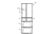
- FIG. 1A is a front view showing a preferred embodiment of the refrigerator of the present invention
- FIG. 1B is a side sectional view showing a preferred embodiment of the refrigerator of the present invention
- FIG. 1C is a state excluding the door in the preferred embodiment of the refrigerator of the present invention.
- FIG. A refrigerator 100 shown in FIGS. 1A to 1C includes a cabinet part 1 and a divider part (partition wall) 2 constituting a refrigerator main body.
- the cabinet part 1 is a box-like thing whose front side is open, and has an outer box 11 that forms an outer shell and an inner box 12 that forms an inner wall. Between the outer box 11 and the inner box 12, for example, A heat insulating material such as urethane is provided.
- the divider unit 2 divides the internal space of the cabinet unit 1 into a plurality of storage rooms, and the internal space of the cabinet unit 1 is, for example, a refrigerator room 3, an ice making room 4, a switching room 5, a freezer room 6, a vegetable room 7. Etc. are divided into storage rooms.
- the refrigerator compartment 3 is provided at the uppermost part of the refrigerator 100, and the front surface is covered with a double door 31 having a heat insulating structure so as to be freely opened and closed.
- the ice making chamber 4 and the switching chamber 5 are provided side by side on the lower side of the refrigeration chamber 3, and the front surfaces of the ice making chamber 4 and the switching chamber 5 are covered with a drawer-type door 41 and a door 51 having a heat insulating structure so as to be freely opened and closed.
- the freezing room 6 is provided below the ice making room 4 and the switching room 5, and the front surface is covered with a drawer-type door 61 having a heat insulating structure so as to be freely opened and closed.
- the vegetable compartment 7 is provided below the freezer compartment 6 and at the bottom of the refrigerator 100, and the front surface is covered with a drawer-type door 71 having a heat insulating structure so as to be freely opened and closed.
- Each door of the storage chambers 3 to 7 is provided with a door opening / closing sensor (not shown) that detects the opening / closing state.
- Each storage room 3-7 is distinguished by a settable temperature zone (set temperature zone).
- the refrigerator compartment 3 is about 0 ° C. to 4 ° C.
- the vegetable compartment 7 is about 3 ° C. to 10 ° C.
- the ice making room. 4 can be set to about -18 ° C
- the freezer compartment 6 can be set to about -16 ° C to -22 ° C.
- the switching chamber 5 can be switched to a temperature range such as chilled (about 0 ° C.) or soft freezing (about ⁇ 7 ° C.).
- the set temperature zones of the refrigerator compartment 3 and the vegetable compartment 7 are set to be higher than the ice making chamber 4, the switching chamber 5, and the freezer compartment 6.
- each of the storage chambers 3 to 7 is not limited to this, and the setting can be changed as appropriate according to the installation location and contents.
- Each of the storage chambers 3 to 7 is provided with a not-shown internal temperature sensor for detecting the temperature of the storage chamber.
- a damper (not shown) is provided on the air passage 14 side of each of the air outlets 32, 42, 52, 62, 72.
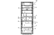
- the cabinet section 1 has a back wall 13 on the back side of each of the storage chambers 3-7.
- An air passage 14 and a cooler chamber 15 are formed between the inner box 12 and the back surface of the back wall 13.
- the air passage 14 is a cold air supply air passage for supplying cold air to each storage chamber, and is provided, for example, in a range facing the back surface of each storage chamber 3-7.
- the cooler chamber 15 is provided, for example, in a range facing the back surface of the freezer compartment 6 and accommodates the cooler 28 of the refrigerating cycle 20. Then, the cold air heat-exchanged by the cooler 28 is supplied from the cooler chamber 15 to the air path 14.
- air outlets for blowing out the cold air flowing through the air passage 14 into the respective storage chambers 3-7 are opened.
- the air outlet 32 is opened in the refrigerator compartment 3
- the air outlet 42 is opened in the ice making chamber 4
- the air outlet 52 is opened in the switching chamber 5, and the freezer compartment 6.
- the air outlet 62 is open, and the vegetable compartment 7 is open with the air outlet 72.
- a damper (not shown) is installed at each of the air outlets 32, 42, 52, 62, and 72, and the temperature of each of the storage chambers 3 to 7 is managed by opening and closing the damper.
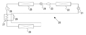
- FIG. 2 is a refrigerant circuit diagram illustrating an example of a refrigeration cycle in the refrigerator of FIGS. 1A to 1C.
- a compressor 21, a condensing pipe 22, a strainer 23, a decompression device 24, a dew condensation prevention pipe 25, a dryer 26, a capillary tube 27, and a cooler 28 are connected in series by piping. .
- the compressor 21 is disposed, for example, in a machine room provided at the lower back of the refrigerator 100.
- the compressor 21 compresses the refrigerant into a high-temperature and high-pressure refrigerant, is driven by an inverter circuit, and the operation capacity is controlled according to the situation.
- the condensation pipe 22 performs heat exchange between the refrigerant discharged from the compressor 21 and the outside air.
- a hot pipe for drain evaporation or an air-cooled condenser placed in the installation space of the compressor 21, It consists of pipes and the like embedded in the side and back of the refrigerator 100 with a heat insulating material.
- the strainer 23 includes a filter that removes dust, metal powder, and the like from the refrigerant that has flowed out of the condensing pipe 22.
- the decompression device 24 decompresses and expands the refrigerant flowing from the condensing pipe 22 via the strainer 23, and is configured such that the opening degree of an electronic expansion valve or the like can be variably controlled. Yes. Further, a dew condensation prevention pipe 25 is connected in series to the decompression device 24 so that the refrigerant flow flowing into the decompression device 24 from the condensing pipe 22 and the strainer 23 flows into the dew condensation prevention pipe 25 without being branched. It has become.
- the condensation prevention pipe 25 is connected in series to the condensation pipe 22 via the decompression device 24, and functions as a condenser together with the condensation pipe 22, and also has a function of preventing condensation in the cabinet part 1 and the divider part 2.
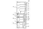
- FIG. 3 is a plan view showing an example of the dew condensation prevention pipe 25 built in the cabinet section 1 of FIG.
- the dew condensation prevention pipe 25 is accommodated by being bent at the peripheral edge of the front opening of the cabinet portion 1 and the front edge of the divider portion 2.
- the dew condensation prevention pipe 25 is installed in the cabinet unit 1 and the divider unit 2 through an elastic member having a large heat capacity such as butyl rubber. Then, when the refrigerant flows through the dew condensation prevention pipe 25, the occurrence of dew condensation on the front surface portion of the refrigerator 100 main body is prevented.
- the dew condensation prevention pipe 25 is illustrated as an example of the case where the dew condensation prevention pipe 25 is disposed on the front side edge of a part of the cabinet unit 1 and the divider unit 2, but the arrangement of the dew condensation prevention pipe 25 is limited thereto. However, it can be arranged at any location where it is possible to suppress dew condensation due to low temperature cold air leaking outside.
- the dew condensation prevention pipe 25 may be disposed on all front side edges of the cabinet unit 1 and the divider unit 2.
- the dew condensation prevention pipe 25 is arrange
- the dryer 26 in FIG. 2 includes a filter that prevents dust, metal powder, and the like contained in the refrigerant flowing from the dew condensation prevention pipe 25 from flowing into the compressor 21, an adsorption member that adsorbs moisture in the refrigeration cycle, and the like.
- the capillary tube 27 is made of, for example, a capillary tube made of copper or the like, and acts as a decompression device that decompresses the refrigerant flowing through the dryer 26 and flows out to the cooler 28 side.
- the cooler 28 is connected between the capillary tube 27 and the suction pipe side of the inter-refrigerant heat exchange unit 29.
- the cooler 28 is provided in the cooler chamber 15 and cools the cooler chamber 15 to generate cold air.
- a circulation fan 16 is provided above the cooler 28. Air is supplied to the cooler 28 by the circulation fan 16, and cool air cooled around the cooler 28 is blown to the storage chambers 3-7. Is done.
- the refrigeration cycle 20 includes an inter-refrigerant heat exchange unit 29 that exchanges heat between the refrigerant flowing through the capillary tube 27 and the refrigerant flowing through the pipe (suction pipe) between the cooler 28 and the compressor 21. Is provided.
- the inter-refrigerant heat exchange unit 29 performs heat exchange between the refrigerant flowing through the capillary tube 27 and the refrigerant sucked into the compressor 21.
- the dew condensation prevention pipe 25 is connected in series to the condensation pipe 22 via the decompression device 24, and has a function as a condenser and a function of preventing condensation. is doing.
- the required cooling capacity is large, it is also necessary to increase the heat radiation amount in the condensation pipe 22 and the dew condensation prevention pipe 25.
- the heat radiation amount in the condensation pipe 22 and the dew condensation prevention pipe 25 is small.
- the cabinet part 1 and the divider part 2 are heated more than necessary by the refrigerant flowing through the dew condensation prevention pipe 25, the heat from the dew condensation prevention pipe 25 flows into each of the storage chambers 3 to 7, and cools each of the storage rooms 3 to 7. Power consumption increases. Therefore, when the internal load is small, it is preferable to control the opening degree of the decompression device 24 so that the temperature of the refrigerant flowing in the dew condensation prevention pipe 25 becomes small.
- condensation may occur in the cabinet part 1 and the divider part 2 when the surface temperature is lower than the dew point temperature. For this reason, it is necessary to maintain the surface temperature of the cabinet part 1 and the divider part 2 to be higher than the dew point temperature of the outside air by using the condensation heat of the refrigerant by lowering the refrigerant pressure of the dew condensation prevention pipe 25 and raising the refrigerant temperature. .
- the refrigerator 100 has a function of implementing a throttle mode (power saving mode) for suppressing power consumption in accordance with an input from the user and the like, and a plurality of throttle modes according to the outside temperature in the installation environment of the refrigerator 100. It has a function to switch and implement.
- a throttle mode power saving mode
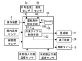
- FIG. 4 is a functional block diagram showing an example of the control device 10 of FIGS. 1A to 1C.
- the refrigerator 100 shown in FIGS. 1A to 1C and 4 includes an operation device 8, an outside air temperature sensor 9a, a humidity sensor 9b, and a control device 10.
- the operating device 8 receives various inputs from the user, and is provided on the surface of the door 31 of the refrigerator compartment 3, for example.
- the operation device 8 includes an operation switch that adjusts the setting of the temperature of each of the storage chambers 3 to 7, a liquid crystal that displays the temperature of each of the storage chambers 3 to 7, and the like.
- the operation device 8 is provided with, for example, an operation switch for selecting an aperture mode, and the user can select any one of the plurality of aperture modes by operating the operation device 8. It has become.
- the outside air temperature sensor 9a detects the outside air temperature TA in the installation environment where the refrigerator 100 is installed.
- the humidity sensor 9b detects the humidity HA of the outside air in the installation environment where the refrigerator 100 is installed.
- the outside air temperature sensor 9a and the humidity sensor 9b are installed at the place of the operation device 8, for example. Note that the outside air temperature sensor 9a and the humidity sensor 9b may be provided at a place other than the operation device 8 (for example, around the connection part between the door 31 of the refrigerator compartment 3 and the cabinet part 1).
- the control device 10 controls the operations of the refrigeration cycle 20 and the refrigerator 100 as a whole, and is configured by a microcomputer or the like and installed at the upper back of the refrigerator 100. Then, the control device 10 controls the operation of the refrigeration cycle 20 and the operation of opening and closing the damper so that the detected value of the internal temperature arranged in each of the storage chambers 3 to 7 becomes the set temperature, for example. Further, the control device 10 detects the open / closed state of each door based on the output from each door open / close sensor. For example, when the door remains open for a long time, the control device 10 or the sound output device reports that effect. To notify the user.
- control device 10 has a function of adjusting the refrigerant pressure in the dew condensation prevention pipe 25 by controlling the opening degree (flow resistance) of the decompression device 24 according to the input of the operation device 8.
- control device 10 includes a setting table 10A, operating condition setting means 10B, and refrigeration cycle control means 10C.
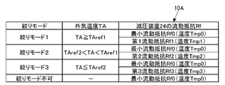
- FIG. 5 is a diagram showing an example of the setting table 10A in FIG.
- the setting table 10A stores different flow resistances Rf0 to Rf3 in association with each outside air temperature TA (throttle mode 1 to 3).
- the operating condition setting means 10B selects one of the throttle modes 1 to 3 from the setting table 10A based on the outside air temperature TA detected by the outside air temperature sensor 9a.
- FIG. 5 shows an example in which three-stage throttle modes 1 to 3 are stored, and flow resistances Rf0 to Rf3 are stored in association with each of the outside air temperatures TA as the throttle modes 1 to 3. Yes.
- TAref1 when the outside air temperature TA is equal to or higher than the first temperature threshold value TAref1 (throttle mode 1), when the outside air temperature TA is smaller than the first temperature threshold value TAref1 and larger than the second temperature threshold value TAref2. (Throttle mode 2), the case where the outside air temperature TA is equal to or lower than the second temperature threshold value TAref2 (throttle mode 3).
- the operating condition setting means 10B selects the flow resistance Rf of the decompression device 24 from the setting table 10A based on the outside air temperature TA and the temperature threshold values TAref1 and TAref2.
- the first flow resistance Rf1 is greater than the minimum flow resistance (fully opened state) Rf0 (Rf1> Rf0)
- the second flow resistance Rf2 is greater than the first flow resistance Rf1 (Rf1> Rf2)
- the third flow The resistance Rf3 is larger than the second flow resistance Rf2 (Rf3> Rf2).
- the flow resistance Rf decreases as the opening of the decompression device 24 increases, and the temperature of the refrigerant flowing through the dew condensation prevention pipe 25 increases as the flow resistance Rf decreases.
- a plurality of different flow resistances Rf0 to Rf3 are associated with each outside air temperature TA (throttle mode 1 to 3).
- the restriction mode 1 is associated with a combination of the minimum flow resistance Rf0 and the first flow resistance Rf1
- the restriction mode 2 is associated with a combination of the minimum flow resistance Rf0 and the second flow resistance Rf2.
- Mode 3 is associated with a combination of minimum flow resistance Rf0 and third flow resistance Rf3.
- the operation condition setting means 10B sets the operation time t for each different flow resistance Rf.
- the temperatures Tmp0 to Tmp3 of the refrigerant flowing through the condensation prevention pipe 25 are stored in advance for each of the flow resistances Rf0 to Rf3.
- the operation condition setting unit 10B operates the operation times t0 and t1 so that the temperature of the refrigerant flowing through the dew condensation prevention pipe 25 is not less than the dew point temperature Td and not more than the outside air temperature TA. Is calculated.
- the case of the throttle mode 1 and the case where the combination of the minimum flow resistance Rf0 and the first flow resistance Rf1 is selected are illustrated.
- the dew point temperature Td in the equation (1) is calculated based on the outside air temperature TA detected by the outside air temperature sensor 9a and the humidity HA detected by the humidity sensor 9b by the operating condition setting unit 10B.
- Various known methods can be used as the method.
- equation (1) is obtained by changing the ratio of the operation time t0 of the minimum flow resistance Rf0 and the operation time t1 of the first flow resistance Rf1 so that the time average value of the temperature of the refrigerant flowing through the dew condensation prevention pipe 25 is the dew point. It means that the flow resistance Rf of the decompression device 24 is adjusted so as to be equal to or higher than the temperature Td and equal to or lower than the outside air temperature TA.
- the operation times t0 and t1 change in proportion depending on the installation environment having different temperatures and humidity. For example, the higher the dew point temperature Td, the more the operation time t0 of the minimum flow resistance Rf0 is the operation of the first flow resistance Rf1. It becomes shorter than time t1.
- the operating condition setting unit 10B illustrates the case where the dew point temperature Td is calculated and the operation time t is calculated using the above equation (1).
- the present invention is not limited to this, and the temperature of the refrigerant is determined from the dew point temperature Td. As long as it is controlled so as to increase.
- the operating condition setting unit 10B may set each operating time t0, so that the average temperature of the refrigerant flowing through the dew condensation prevention pipe 25 becomes the outside air temperature TA, or so as to be lower than the outside air temperature TA by a predetermined temperature (for example, 5 ° C.). You may make it calculate t1.
- the humidity sensor 9b for calculating the dew point temperature Td is not required, and the power consumption in the refrigerator 100 due to the heat of the dew condensation prevention pipe 25 can be suppressed with an inexpensive configuration while reliably preventing the occurrence of dew condensation. it can.
- the operation times t0 and t1 are calculated using the formula (1) is illustrated, the operation times t0 to t3 for each of the flow resistances Rf0 to Rf3 are also stored in the setting table 10A in advance.
- the flow resistance Rf and the operation time t stored in the setting table 10A may be set according to the outside air temperature TA.
- the operating condition setting means 10B performs the flow that matches the aperture modes 1 to 3 selected by the user from the setting table 10A. It has a function of selecting the resistor Rf. In this way, not only the case of automatically shifting to the aperture mode, but also a countermeasure for preventing condensation can be performed manually according to a request from the user.
- the operation time t may be calculated by the equation (1), or may be previously stored in the setting table 10A.
- the refrigeration cycle control means 10C controls the refrigeration cycle 20 so that the throttling mode (power saving operation) according to the throttling modes 1 to 3 (flow resistance Rf and operating time t) set in the operating condition setting means 10B is performed. is there. Specifically, the refrigeration cycle control means 10C starts driving the compressor 21 and controls the refrigeration cycle 20 so that the flow resistances Rf0 and Rf1 of the decompression device 24 and the operation times t0 and t1 thereof are reached.
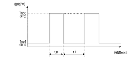
- FIG. 6 is a graph showing how the opening of the decompression device 24 is controlled during operation of the refrigeration cycle 20 of FIG.
- the refrigeration cycle control means 10C controls the decompression device 24 so that the operation time t0 by the minimum flow resistance Rf0 and the operation time t1 by the first flow resistance Rf1 are alternately switched. Then, in the period of the operation time t0 due to the minimum flow resistance Rf0, the temperature of the refrigerant flowing through the dew condensation prevention pipe 25 becomes Tmp0, and in the period of the operation time t0 due to the first flow resistance Rf1, the temperature of the refrigerant is Tmp1 ( ⁇ Tmp0). And the time average value of the temperature of the refrigerant
- the refrigeration cycle control means 10C may forcibly cancel the throttling modes 1 to 3 according to the internal load. For example, when the internal load becomes a predetermined threshold value or more, the refrigeration cycle control means 10C cancels the restriction mode in order to prevent insufficient cooling, or disables the restriction mode setting. You may control as follows.
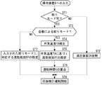
- FIG. 7 is a flowchart showing an operation example of the refrigerator of FIGS. 1A to 1C, and an operation example of the refrigerator 100 will be described with reference to FIGS. 1A to 1C to 7. Note that, as an initial state, the refrigerator 100 is not set to any throttle mode, and the decompression device 24 does not adjust the refrigerant pressure, that is, the refrigerant pressure loss in the decompression device 24 is minimized. Assume that the status is set.
- step ST1 whether or not to shift to the aperture mode 1 to 3 is input to the operation device 8 by the user's operation.
- the refrigeration cycle control means 10C is set so that the decompression device 24 is fully opened (minimum flow resistance Rf0) (Ste ST2). Then, the operation is performed in a state where the cooling capacity of the refrigerator 100 is maximized (step ST8).
- the operating condition setting unit 10B further automatically selects the aperture modes 1 to 3 from the operating device 8. It is determined whether or not an input has been made (step ST3).
- the outside air temperature TA detected by the outside air temperature sensor 9a is acquired in the operating condition setting unit 10B (step ST4).
- the operation condition setting means 10B selects the throttle modes 1 to 3 (flow resistance Rf) from the setting table 10A based on the outside air temperature TA (step ST5).
- the operation time t for each flow resistance Rf is set based on the equation (1) and the like (step ST6).
- step ST8 the operation of the compressor 21 is started (step ST8), and the driving of the decompression device 24 by the set flow resistance Rf and operation time is controlled.
- the refrigerant temperature (refrigerant pressure) of the dew condensation prevention pipe 25 is controlled to be equal to or higher than the dew point temperature Td and further equal to or lower than the outside air temperature (see FIG. 6).
- the operating condition setting unit 10B associates the aperture mode with the aperture modes 1 to 3 input to the operating device 8.
- the flow resistance Rf is set (step ST7), and the operation time t is set.
- the setting of the operation time t may be calculated using the equation (1) as described above, or the operation time t stored in advance in association with the flow resistance Rf may be used.
- the operation of the compressor 21 is started (step ST8).
- the flow resistance Rf is set using the setting table 10A, and the operation time t based on the set flow resistance Rf is set.
- the temperature of the refrigerant flowing through the dew condensation prevention pipe 25 can be secured to the dew point temperature Td or higher. Therefore, any outside air such as when the outside air is high humidity (for example, RH 90% or more), low humidity (for example, RH 50% or more), high outside air (for example, 30 ° C.), or low outside air (for example, 15 ° C.). Even at the temperature TA, it is possible to reliably prevent the occurrence of condensation regardless of the outside air environment while suppressing power consumption.
- the state of the refrigerant flowing through the refrigeration cycle 20 is monitored as in the past, and the opening of the decompression device 24 is changed accordingly.
- the refrigerant temperature can be controlled to a predetermined refrigerant temperature by utilizing the change in the temperature of the refrigerant flowing through the dew condensation prevention pipe 25 in accordance with the flow resistances Rf0 to Rf3. For this reason, it is possible to prevent condensation that matches the installation environment at low cost without installing a refrigerant temperature sensor, a refrigerant pressure sensor, or the like and monitoring the state of the refrigerant.
- control device 10 enters the aperture mode when the aperture mode 1 to 3 is performed when the operation device 8 receives an input indicating that the aperture mode can be performed, for example, when the internal load is high. If not, the decompression device 24 is fully opened and the condensation prevention pipe 25 is used as a condenser so that the refrigerant can be condensed in the condensation prevention pipe 25 in addition to the condensation pipe 22, so that the necessary amount of condensation heat is secured. Can continue to cool.
- the refrigerant temperature can be controlled with high accuracy, and the installation environment is not limited. Even in such a case, it is possible to reliably prevent the occurrence of condensation.
- the embodiment of the present invention is not limited to the above embodiment.
- FIG. 4 the case where the outside air temperature TA is classified into three regions is illustrated, but any temperature thresholds TAref1 and Tref2 defined by two or more may be used.
- the setting table 10A of FIG. 4 the case where the combination of the minimum flow resistance Rf0 and each of the flow resistances Rf1 to Rf3 is illustrated, but not limited to this combination, the flow resistances Rf0 to Rf3 are not limited to this combination. Any combination may be stored.
- one flow resistance may be stored, or a combination of three or more different flow resistances may be stored.
Abstract
Description

Claims (10)
- 内部空間を有するキャビネット部と、
前記キャビネット部の内部空間を複数の貯蔵室に仕切るディバイダ部と、
前記キャビネット部に収容され、圧縮機、凝縮パイプ、減圧装置、結露防止パイプ、キャピラリーチューブの順に直列に接続された冷凍サイクルと、
前記キャビネット部の外部に設置され、外気温度を検出する外気温度センサと、
前記冷凍サイクルの動作を制御する制御装置と
を備え、
前記制御装置は、
前記外気温度毎に異なる前記減圧装置の流動抵抗が関連付けて記憶された設定テーブルと、
前記外気温度センサにより検出された前記外気温度に基づいて、前記設定テーブルから前記流動抵抗を選択するとともに、選択した前記流動抵抗での運転時間を設定する運転条件設定手段と、
前記運転条件設定手段において設定された前記流動抵抗及び前記運転時間による運転が行われるように、前記冷凍サイクルを制御する冷凍サイクル制御手段と
を有する冷蔵庫。 - 前記流動抵抗の調整の可否を受け付ける操作装置をさらに備え、
前記制御装置は、前記操作装置に前記流動抵抗の選択が可能である旨の入力を受け付けた場合に、前記冷凍サイクルの前記流動抵抗の選択及び前記運転時間の設定を行うものである請求項1に記載の冷蔵庫。 - 前記操作装置は、前記設定テーブルからの前記流動抵抗の選択を直接入力するための操作スイッチを備えたものであり、
前記運転条件設定手段は、前記操作装置から入力された前記流動抵抗を選択する機能を有する請求項2に記載の冷蔵庫。 - 前記設定テーブルには、異なる複数の前記流動抵抗が前記外気温度毎に記憶されたものであり、
前記運転条件設定手段は、異なる前記流動抵抗毎にそれぞれ前記運転時間を設定するものである請求項1~3のいずれか1項に記載の冷蔵庫。 - 前記設定テーブルには、前記流動抵抗毎に前記結露防止パイプに流れる冷媒の温度が予め記憶されており、
前記運転条件設定手段は、前記結露防止パイプに流れる冷媒の平均温度が露点温度よりも大きくなるように、異なる前記流動抵抗毎にそれぞれ前記運転時間を設定するものである請求項4に記載の冷蔵庫。 - 前記冷凍サイクル制御手段は、前記結露防止パイプを流れる冷媒の平均温度が前記外気温度になるように、異なる前記流動抵抗毎にそれぞれ前記運転時間を設定するものである請求項5に記載の冷蔵庫。
- 前記冷凍サイクル制御手段は、前記結露防止パイプを流れる冷媒の平均温度が前記外気温度から所定温度だけ低くなるように、異なる前記流動抵抗毎にそれぞれ前記運転時間を設定するものである請求項5に記載の冷蔵庫。
- 外気の湿度を検出する湿度センサをさらに備え、
前記冷凍サイクル制御手段は、前記湿度センサにより検出された前記湿度及び前記外気温度から前記露点温度を算出し、前記結露防止パイプを流れる冷媒の温度が前記露点温度より大きくなるように、異なる前記流動抵抗毎にそれぞれ前記運転時間を設定するものである請求項5に記載の冷蔵庫。 - 前記設定テーブルには、前記外気温度が3つに分類されている請求項1~8のいずれか1項に記載の冷蔵庫。
- 前記結露防止パイプは、前記キャビネット部及び前記ディバイダ部の前面側の縁の少なくとも一部に収容されている請求項1~9のいずれか1項に記載の冷蔵庫。
Priority Applications (8)
| Application Number | Priority Date | Filing Date | Title |
|---|---|---|---|
| RU2016107823A RU2624679C1 (ru) | 2013-08-09 | 2014-06-26 | Холодильник |
| SG11201509559SA SG11201509559SA (en) | 2013-08-09 | 2014-06-26 | Refrigerator |
| MYPI2016700456A MY186071A (en) | 2013-08-09 | 2014-06-26 | Refrigerator |
| AU2014303819A AU2014303819B2 (en) | 2013-08-09 | 2014-06-26 | Refrigerator |
| TW103125053A TW201530069A (zh) | 2013-08-09 | 2014-07-22 | 冰箱 |
| CN201420442987.8U CN204202274U (zh) | 2013-08-09 | 2014-08-07 | 冰箱 |
| CN201410385526.6A CN104344637A (zh) | 2013-08-09 | 2014-08-07 | 冰箱 |
| HK15106698.5A HK1206095A1 (en) | 2013-08-09 | 2015-07-14 | Refrigerator |
Applications Claiming Priority (2)
| Application Number | Priority Date | Filing Date | Title |
|---|---|---|---|
| JP2013166060A JP6366237B2 (ja) | 2013-08-09 | 2013-08-09 | 冷蔵庫 |
| JP2013-166060 | 2013-08-09 |
Publications (1)
| Publication Number | Publication Date |
|---|---|
| WO2015019740A1 true WO2015019740A1 (ja) | 2015-02-12 |
Family
ID=52461079
Family Applications (1)
| Application Number | Title | Priority Date | Filing Date |
|---|---|---|---|
| PCT/JP2014/067061 WO2015019740A1 (ja) | 2013-08-09 | 2014-06-26 | 冷蔵庫 |
Country Status (9)
| Country | Link |
|---|---|
| JP (1) | JP6366237B2 (ja) |
| CN (2) | CN104344637A (ja) |
| AU (1) | AU2014303819B2 (ja) |
| HK (1) | HK1206095A1 (ja) |
| MY (1) | MY186071A (ja) |
| RU (1) | RU2624679C1 (ja) |
| SG (1) | SG11201509559SA (ja) |
| TW (1) | TW201530069A (ja) |
| WO (1) | WO2015019740A1 (ja) |
Families Citing this family (5)
| Publication number | Priority date | Publication date | Assignee | Title |
|---|---|---|---|---|
| JP6366237B2 (ja) * | 2013-08-09 | 2018-08-01 | 三菱電機株式会社 | 冷蔵庫 |
| US10323875B2 (en) * | 2015-07-27 | 2019-06-18 | Illinois Tool Works Inc. | System and method of controlling refrigerator and freezer units to reduce consumed energy |
| CN106813440B (zh) * | 2015-11-27 | 2019-10-29 | 日立环球生活方案株式会社 | 冰箱 |
| JP6819377B2 (ja) * | 2017-03-14 | 2021-01-27 | オムロン株式会社 | Rfidデータ管理装置、rfidデータ管理方法、および、rfidデータ管理プログラム |
| CN112665299B (zh) * | 2020-12-11 | 2022-07-01 | 珠海格力电器股份有限公司 | 冰箱的制冷控制方法、装置、控制器和冰箱 |
Citations (9)
| Publication number | Priority date | Publication date | Assignee | Title |
|---|---|---|---|---|
| JPS5421660A (en) * | 1977-07-20 | 1979-02-19 | Hitachi Ltd | Refrigerator |
| JPH1047836A (ja) * | 1996-08-06 | 1998-02-20 | Matsushita Refrig Co Ltd | 冷凍機能付冷蔵装置 |
| JP2003106684A (ja) * | 2001-09-28 | 2003-04-09 | Matsushita Electric Ind Co Ltd | 冷凍サイクルの制御方法 |
| JP2004353972A (ja) * | 2003-05-29 | 2004-12-16 | Toshiba Corp | 冷蔵庫 |
| JP2005156111A (ja) * | 2003-11-28 | 2005-06-16 | Matsushita Electric Ind Co Ltd | 冷蔵庫 |
| JP2007078205A (ja) * | 2005-09-12 | 2007-03-29 | Sanyo Electric Co Ltd | 冷蔵庫 |
| JP2012017920A (ja) * | 2010-07-08 | 2012-01-26 | Toshiba Corp | 冷蔵庫 |
| JP2013061089A (ja) * | 2011-09-12 | 2013-04-04 | Hitachi Appliances Inc | 冷蔵庫 |
| JP2013072595A (ja) * | 2011-09-28 | 2013-04-22 | Hitachi Appliances Inc | 冷蔵庫および冷凍庫 |
Family Cites Families (9)
| Publication number | Priority date | Publication date | Assignee | Title |
|---|---|---|---|---|
| CH482080A (de) * | 1969-03-26 | 1969-11-30 | Brandestini Antonio | Ankerkörper für Spannglieder |
| SU879192A1 (ru) * | 1978-10-24 | 1981-11-07 | Московский Специализированный Комбинат Холодильного Оборудования | Холодильна установка |
| JPH06221739A (ja) * | 1992-12-01 | 1994-08-12 | Hitachi Ltd | 冷蔵庫 |
| JPH07260297A (ja) * | 1994-03-17 | 1995-10-13 | Matsushita Refrig Co Ltd | 冷凍装置 |
| BRPI0601967B1 (pt) * | 2006-06-01 | 2021-03-23 | Embraco Indústria De Compressores E Soluções Em Refrigeração Ltda. | Sistema e método de controle de operação de um sistema de refrigeração |
| ITTO20060767A1 (it) * | 2006-10-24 | 2008-04-25 | Indesit Co Spa | Apparecchio di refrigerazione |
| CN201344692Y (zh) * | 2008-11-24 | 2009-11-11 | 海信(北京)电器有限公司 | 可自动调节制冷剂流量的电冰箱 |
| JP5656494B2 (ja) * | 2010-07-20 | 2015-01-21 | 株式会社東芝 | 冷蔵庫 |
| JP6366237B2 (ja) * | 2013-08-09 | 2018-08-01 | 三菱電機株式会社 | 冷蔵庫 |
-
2013
- 2013-08-09 JP JP2013166060A patent/JP6366237B2/ja not_active Expired - Fee Related
-
2014
- 2014-06-26 AU AU2014303819A patent/AU2014303819B2/en active Active
- 2014-06-26 SG SG11201509559SA patent/SG11201509559SA/en unknown
- 2014-06-26 WO PCT/JP2014/067061 patent/WO2015019740A1/ja active Application Filing
- 2014-06-26 RU RU2016107823A patent/RU2624679C1/ru active
- 2014-06-26 MY MYPI2016700456A patent/MY186071A/en unknown
- 2014-07-22 TW TW103125053A patent/TW201530069A/zh unknown
- 2014-08-07 CN CN201410385526.6A patent/CN104344637A/zh active Pending
- 2014-08-07 CN CN201420442987.8U patent/CN204202274U/zh not_active Expired - Fee Related
-
2015
- 2015-07-14 HK HK15106698.5A patent/HK1206095A1/xx unknown
Patent Citations (9)
| Publication number | Priority date | Publication date | Assignee | Title |
|---|---|---|---|---|
| JPS5421660A (en) * | 1977-07-20 | 1979-02-19 | Hitachi Ltd | Refrigerator |
| JPH1047836A (ja) * | 1996-08-06 | 1998-02-20 | Matsushita Refrig Co Ltd | 冷凍機能付冷蔵装置 |
| JP2003106684A (ja) * | 2001-09-28 | 2003-04-09 | Matsushita Electric Ind Co Ltd | 冷凍サイクルの制御方法 |
| JP2004353972A (ja) * | 2003-05-29 | 2004-12-16 | Toshiba Corp | 冷蔵庫 |
| JP2005156111A (ja) * | 2003-11-28 | 2005-06-16 | Matsushita Electric Ind Co Ltd | 冷蔵庫 |
| JP2007078205A (ja) * | 2005-09-12 | 2007-03-29 | Sanyo Electric Co Ltd | 冷蔵庫 |
| JP2012017920A (ja) * | 2010-07-08 | 2012-01-26 | Toshiba Corp | 冷蔵庫 |
| JP2013061089A (ja) * | 2011-09-12 | 2013-04-04 | Hitachi Appliances Inc | 冷蔵庫 |
| JP2013072595A (ja) * | 2011-09-28 | 2013-04-22 | Hitachi Appliances Inc | 冷蔵庫および冷凍庫 |
Also Published As
| Publication number | Publication date |
|---|---|
| AU2014303819A1 (en) | 2015-12-24 |
| RU2624679C1 (ru) | 2017-07-05 |
| TW201530069A (zh) | 2015-08-01 |
| AU2014303819B2 (en) | 2016-10-13 |
| SG11201509559SA (en) | 2016-03-30 |
| TWI560415B (ja) | 2016-12-01 |
| CN104344637A (zh) | 2015-02-11 |
| HK1206095A1 (en) | 2015-12-31 |
| MY186071A (en) | 2021-06-18 |
| CN204202274U (zh) | 2015-03-11 |
| JP2015034673A (ja) | 2015-02-19 |
| JP6366237B2 (ja) | 2018-08-01 |
Similar Documents
| Publication | Publication Date | Title |
|---|---|---|
| US7975497B2 (en) | Refrigeration unit having variable performance compressor operated based on high-pressure side pressure | |
| JP6334146B2 (ja) | 冷蔵庫 | |
| JP6168980B2 (ja) | 冷蔵庫 | |
| WO2015019740A1 (ja) | 冷蔵庫 | |
| JP2014020715A (ja) | 冷蔵庫 | |
| WO2012169182A1 (ja) | 冷凍装置 | |
| JP2012017920A (ja) | 冷蔵庫 | |
| JP2007071520A (ja) | 冷却貯蔵庫及びその圧縮機の制御方法 | |
| JP6355325B2 (ja) | 冷蔵庫、及び、冷蔵庫の制御方法 | |
| AU2015268480B2 (en) | Refrigerator | |
| JP5506760B2 (ja) | 冷蔵庫 | |
| KR20150058995A (ko) | 냉장고 및 그 제어 방법 | |
| JP2007309585A (ja) | 冷凍装置 | |
| AU2015410544B2 (en) | Refrigerator | |
| JP5579290B1 (ja) | 冷蔵庫 | |
| JP5818993B2 (ja) | 冷蔵庫 | |
| KR20080068233A (ko) | 냉장고의 과냉각 방지 장치 및 방법 | |
| KR100526605B1 (ko) | 냉장고 및 냉장고 운전제어방법 | |
| JP5501407B2 (ja) | 冷蔵庫 | |
| JP2016044875A (ja) | 冷蔵庫 | |
| JP2013053801A (ja) | 冷蔵庫 | |
| JP2015036600A (ja) | 冷蔵庫 | |
| JP2004092939A (ja) | 冷凍冷蔵庫 | |
| JP2013238378A (ja) | 冷蔵庫 | |
| JP2014081107A (ja) | 冷蔵庫 |
Legal Events
| Date | Code | Title | Description |
|---|---|---|---|
| 121 | Ep: the epo has been informed by wipo that ep was designated in this application |
Ref document number: 14833780 Country of ref document: EP Kind code of ref document: A1 |
|
| ENP | Entry into the national phase |
Ref document number: 2014303819 Country of ref document: AU Date of ref document: 20140626 Kind code of ref document: A |
|
| NENP | Non-entry into the national phase |
Ref country code: DE |
|
| ENP | Entry into the national phase |
Ref document number: 2016107823 Country of ref document: RU Kind code of ref document: A |
|
| 122 | Ep: pct application non-entry in european phase |
Ref document number: 14833780 Country of ref document: EP Kind code of ref document: A1 |