WO2015019720A1 - 車両の骨格構造 - Google Patents
車両の骨格構造 Download PDFInfo
- Publication number
- WO2015019720A1 WO2015019720A1 PCT/JP2014/066212 JP2014066212W WO2015019720A1 WO 2015019720 A1 WO2015019720 A1 WO 2015019720A1 JP 2014066212 W JP2014066212 W JP 2014066212W WO 2015019720 A1 WO2015019720 A1 WO 2015019720A1
- Authority
- WO
- WIPO (PCT)
- Prior art keywords
- wall
- vehicle
- bent portion
- reinforcing member
- connecting plate
- Prior art date
- Legal status (The legal status is an assumption and is not a legal conclusion. Google has not performed a legal analysis and makes no representation as to the accuracy of the status listed.)
- Ceased
Links
Images


Classifications
-
- B—PERFORMING OPERATIONS; TRANSPORTING
- B62—LAND VEHICLES FOR TRAVELLING OTHERWISE THAN ON RAILS
- B62D—MOTOR VEHICLES; TRAILERS
- B62D21/00—Understructures, i.e. chassis frame on which a vehicle body may be mounted
- B62D21/02—Understructures, i.e. chassis frame on which a vehicle body may be mounted comprising longitudinally or transversely arranged frame members
-
- B—PERFORMING OPERATIONS; TRANSPORTING
- B62—LAND VEHICLES FOR TRAVELLING OTHERWISE THAN ON RAILS
- B62D—MOTOR VEHICLES; TRAILERS
- B62D25/00—Superstructure or monocoque structure sub-units; Parts or details thereof not otherwise provided for
- B62D25/20—Floors or bottom sub-units
- B62D25/2009—Floors or bottom sub-units in connection with other superstructure subunits
- B62D25/2045—Floors or bottom sub-units in connection with other superstructure subunits the subunits being fire walls
-
- B—PERFORMING OPERATIONS; TRANSPORTING
- B62—LAND VEHICLES FOR TRAVELLING OTHERWISE THAN ON RAILS
- B62D—MOTOR VEHICLES; TRAILERS
- B62D25/00—Superstructure or monocoque structure sub-units; Parts or details thereof not otherwise provided for
- B62D25/20—Floors or bottom sub-units
- B62D25/2009—Floors or bottom sub-units in connection with other superstructure subunits
-
- B—PERFORMING OPERATIONS; TRANSPORTING
- B62—LAND VEHICLES FOR TRAVELLING OTHERWISE THAN ON RAILS
- B62D—MOTOR VEHICLES; TRAILERS
- B62D25/00—Superstructure or monocoque structure sub-units; Parts or details thereof not otherwise provided for
- B62D25/20—Floors or bottom sub-units
- B62D25/2009—Floors or bottom sub-units in connection with other superstructure subunits
- B62D25/2027—Floors or bottom sub-units in connection with other superstructure subunits the subunits being rear structures
-
- B—PERFORMING OPERATIONS; TRANSPORTING
- B62—LAND VEHICLES FOR TRAVELLING OTHERWISE THAN ON RAILS
- B62D—MOTOR VEHICLES; TRAILERS
- B62D29/00—Superstructures, understructures, or sub-units thereof, characterised by the material thereof
- B62D29/001—Superstructures, understructures, or sub-units thereof, characterised by the material thereof characterised by combining metal and synthetic material
- B62D29/005—Superstructures, understructures, or sub-units thereof, characterised by the material thereof characterised by combining metal and synthetic material preformed metal and synthetic material elements being joined together, e.g. by adhesives
Definitions
- the present invention relates to a vehicle skeleton structure.
- a vehicle skeleton member structure in which an internal skeleton member having a closed cross-sectional structure is disposed in a curved portion of a vehicle skeleton member having a closed cross-sectional structure, and bending deformation generated in the curved portion due to input of a load is suppressed.
- an object of the present invention is to obtain a vehicle skeleton structure capable of suppressing bending deformation generated in the skeleton member by input of a load.
- the skeleton structure of the vehicle according to the first aspect of the present invention is a closed cross-sectional structure having a plurality of wall portions constituting the skeleton of the vehicle, and is bent or curved in the middle in the longitudinal direction.
- a fiber having a bent skeleton member having a bent portion and a pair of side walls having a bent flat plate shape or a curved flat plate shape along the bent portion, and disposed in a closed cross-sectional structure in the bent portion of the skeleton member A reinforcing member made of reinforced resin, and a connecting plate for connecting the pair of side walls of the reinforcing member and connecting the wall portion on the compression deformation side and the wall portion on the tensile deformation side in the bent portion, Yes.
- the reinforcing member is disposed in the closed cross-sectional structure in the bent portion of the skeleton member, and the connecting plate that connects the pair of side walls of the reinforcing member is the compression deformation side in the bent portion.
- the connecting plate of the reinforcing member is dispersed by the connecting plate of the reinforcing member. Therefore, the bending deformation which generate
- a vehicle skeleton structure according to a second aspect of the present invention is the vehicle skeleton structure according to the first aspect, wherein the reinforcing member connects the pair of side walls and intersects the connecting plate.
- the reinforcing member connects the pair of side walls and intersects the connecting plate.
- One or a plurality of partition walls arranged at an angle.
- one or a plurality of partition walls that connect between the pair of side walls of the reinforcing member are arranged at an angle that intersects the connecting plate. Therefore, the strength (rigidity) of the reinforcing member can be improved as compared with the case where the reinforcing member does not have the partition wall.
- the vehicle skeleton structure according to the third aspect of the present invention is the vehicle skeleton structure according to the second aspect, wherein the partition wall is provided at the maximum bent portion or the maximum curvature portion of the bent portion. . *
- the partition wall is provided at the maximum bent portion or the maximum curvature portion of the bent portion. Therefore, the strength (rigidity) of the reinforcing member can be further improved as compared with the case where the partition wall is not provided at the maximum bent portion or the maximum curvature portion in the bent portion.
- the vehicle skeleton structure according to the fourth aspect of the present invention is the vehicle skeleton structure according to the second or third aspect, wherein the partition wall is provided on one end side in the longitudinal direction of the side wall. .
- the partition wall is provided on one end side in the longitudinal direction of the side wall. Therefore, the strength (rigidity) of the reinforcing member can be further improved as compared with the case where the partition wall is not provided on one end side in the longitudinal direction of the side wall.
- the vehicle skeleton structure according to the fifth aspect of the present invention is the vehicle skeleton structure according to any one of the first to fourth aspects, and the orientation of the fibers in the connecting plate is the extension of the connecting plate. Along the direction.
- the fiber orientation in the connecting plate is along the extending direction of the connecting plate. Therefore, the strength (rigidity) of the connecting plate can be improved as compared to the case where the fiber orientation in the connecting plate is not along the extending direction of the connecting plate.
- the vehicle skeleton structure according to the sixth aspect of the present invention is the vehicle skeleton structure according to any one of the first to fifth aspects, and the orientation of fibers in the side wall is determined by the tensile deformation of the side wall. It is parallel to an imaginary straight line connecting one end and the other end in the longitudinal direction along the side wall.
- the fiber orientation on the side wall is parallel to a virtual straight line connecting the one end and the other end in the longitudinal direction along the wall on the side of the tensile deformation. Therefore, the strength (rigidity) of the side wall can be improved as compared with the case where the fiber orientation on the side wall is not parallel to the virtual straight line.
- the strength of the reinforcing member can be improved.
- the strength of the reinforcing member can be further improved.
- the strength of the reinforcing member can be further improved.
- the strength of the connecting plate can be improved.
- the strength of the side wall can be improved.
- FIG. 4 is a cross-sectional view taken along line XX in FIG. 3. It is a top view which shows orientation of the fiber of the connection board in the reinforcement member which concerns on this embodiment. It is a side view which shows the orientation of the fiber of the side wall in the reinforcement member which concerns on this embodiment.
- an arrow UP appropriately shown in each drawing is an upward direction of the vehicle body
- an arrow FR is a forward direction of the vehicle body
- an arrow OUT is an outer side of the vehicle width direction.
- the vertical direction of the vehicle body, the front / rear direction of the vehicle body direction, and the left / right direction of the vehicle body are indicated.
- the left side of the vehicle 12 provided with the skeleton structure 10 according to the present embodiment is shown in FIG. 1, the right side of the vehicle 12 is the same in the left-right symmetry.
- a pair of left and right front side members 14 as a skeleton member having a closed cross-sectional structure with the longitudinal direction of the vehicle body as a longitudinal direction are disposed on both sides of the front portion of the vehicle 12.
- An inclined portion (kick portion) 14A is formed in the middle of each front side member 14 in the longitudinal direction, and each front side member 14 has a predetermined height higher than the inclined portion 14A on the vehicle front side than the vehicle rear side. It extends in the longitudinal direction of the vehicle body at a high position (high position).
- a pair of left and right rear floor side members 16 as a skeleton member having a closed cross-sectional structure with the longitudinal direction of the vehicle body as the longitudinal direction are disposed on both sides of the rear portion of the vehicle 12.
- An inclined portion (kick portion) 16A is formed in the middle in the longitudinal direction of each rear floor side member 16, and each rear floor side member 16 has a predetermined height on the rear side of the vehicle body relative to the front side of the vehicle body relative to each inclined portion 16A. It extends in the longitudinal direction of the vehicle body at a high position (high position).
- the front side member 14 and the rear floor side member 16 are integrally formed continuously via a floor member 15 as a skeleton member having a closed cross-sectional structure extending in the longitudinal direction of the vehicle body. Further, since the skeleton structure 10 of the vehicle 12 on the rear floor side member 16 side is the same as the skeleton structure 10 of the vehicle 12 on the front side member 14 side, the skeleton structure 10 of the vehicle 12 on the front side member 14 side will be described below. Will be described.
- the vehicle 12 extends along the upper surface of the inclined portion 14A of the front side member 14, and extends from the front end portion of the inclined portion 14A toward the vehicle body upward.
- a substantially flat dash panel 18 is provided as a wall section that partitions the compartment room 17 and the vehicle compartment 20.
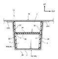
- the inclined portion 14 ⁇ / b> A of the front side member 14 is formed in a hat-shaped cross section by an inner wall 22, an outer wall 24, and a lower wall 26 as wall portions, and an upper end portion and an outer wall of the inner wall 22 are formed.
- the flange portions 22A and 24A respectively formed on the upper end portion of 24 are joined to the lower surface of the dash panel 18 by welding or the like, whereby a closed cross-sectional structure is configured.
- the front end portion and the rear end portion (boundary portion with the floor member 15) of the inclined portion 14A are a front bent portion 27 and a rear bent portion 28, respectively.
- the front bent portion 27 is a bent portion that is bent (or curved) so as to be convex toward the upper side of the vehicle body
- the rear bent portion 28 is bent (or curved) so as to be convex toward the lower side of the vehicle body. It is a bent part.
- the front bent portion 27 uses the maximum bent portion (or the maximum curvature portion) as a deformation starting point.
- the rear bent portion 28 is bent and deformed downward from the vehicle body, with the maximum bent portion (or maximum curvature portion) L (see FIG. 3) as a deformation starting point.
- the lower wall 26 side of the front side member 14 is a wall portion on the compression deformation side (stress concentration side), and the dash panel 18 side is a wall portion on the tensile deformation side.
- the dash panel 18 side of the front side member 14 becomes a wall portion on the compression deformation side (stress concentration side)
- the lower wall 26 side becomes a wall portion on the tensile deformation side.
- the reinforcing member 30 is also arranged in the closed cross-sectional structure at the front bent portion of the rear floor side member 16.
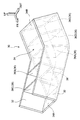
- the reinforcing member 30 has a longitudinal direction in which the front side member 14 extends, a pair of side walls 32 facing each other, and an extending direction of the floor member 15 in the longitudinal direction.
- a substantially rectangular flat plate-like connecting plate 34 that integrally connects the pair of side walls 32. Specifically, both ends of the connecting plate 34 in the short direction (vehicle width direction) are joined to the inner surface of each side wall 32 by an adhesive J (see FIG. 4).
- each outer surface of a pair of side wall 32 is joined to the inner surface of the inner wall 22 in the back side bending part 28, and the inner surface of the outer wall 24 with the adhesive agent J, respectively. Accordingly, the front side member 14 is disposed within the closed cross-sectional structure. Note that the illustration of the adhesive J is omitted in each figure except FIG. Further, as the adhesive J in the present embodiment, a structural adhesive having a high adhesive strength is used.
- Each side wall 32 is formed in a bent flat plate shape (or a curved flat plate shape) along the rear bent portion 28 when viewed from the facing direction (vehicle width direction) (in a side view shown in FIG. 3).
- board thickness of each side wall 32 should just have a certain amount of intensity
- the connecting plate 34 extends along the longitudinal direction of the floor member 15 on the rear side of the rear bent portion 28, and is bent along the lower wall 26 in the inclined portion 14A.
- the lower surface of the portion 34A is joined to the inner surface of the lower wall 26 by an adhesive J
- the upper surface of the rear end portion 34B is joined to the lower surface of the dash panel 18 by the adhesive J.
- the connecting plate 34 includes a lower wall 26 of the front side member 14 that is a tensile deformation side wall portion of the rear bent portion 28, and a dash panel 18 that is a compressive deformation side wall portion of the rear bent portion 28.
- a dash panel 18 that is a compressive deformation side wall portion of the rear bent portion 28.
- the pair of side walls 32 (including a partition wall 36 described later) and the connecting plate 34 constituting the reinforcing member 30 are each manufactured by injection molding.
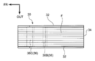
- the connecting plate 34 is formed by injecting and molding a fiber reinforced resin material from a gate of a mold (not shown) located at the center of the rear end thereof, so that the fiber F can be seen in a plan view shown in FIG. The orientation is along the extending direction (longitudinal direction of the floor member 15).
- each side wall 32 is shown by FIG. 5B by inject
- the orientation of the fibers F is parallel to a virtual straight line K connecting the rear lower end 32B and the front lower end 32A.
- parallel in the present embodiment includes substantially parallel slightly deviated from exact parallel.
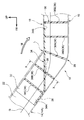
- the reinforcing member 30 has a plurality of (for example, five) partition walls 36 that connect between the pair of side walls 32.
- Each partition wall 36 is disposed at an angle intersecting the connecting plate 34 and at a predetermined interval in a side view shown in FIG.
- the partition walls 36 are arranged at an angle perpendicular to the lower wall 26 and at equal intervals in the longitudinal direction of the front side member 14.
- each partition wall 36 is formed integrally with the side wall 32, and is substantially the same height as the side wall 32.
- the orientation of the fiber F in the partition wall 36 is not particularly limited.
- the thickness of the partition wall 36 is not particularly limited.
- the plate thickness of the partition wall 36 may be the same as the plate thickness of the side wall 32 or the connection plate 34, or may be formed slightly thinner.
- each partition wall 36 exposed to the upper side and the lower side without being joined to the connecting plate 34 are joined to the lower surface of the dash panel 18 and the inner surface of the lower wall 26 by an adhesive J, respectively. Yes.
- the cross-sectional deformation of the front side member 14 at the rear bent portion 28 is suppressed or prevented.
- the partition wall 36 is disposed at least in the maximum bent portion (or maximum curvature portion) L in the rear bent portion 28.
- the “maximum bent portion (or maximum curvature portion) L” in the present embodiment includes a position slightly deviated from the accurate maximum bent portion (or maximum curvature portion) in the front-rear direction.
- the partition wall 36 is desirably disposed also on the rear end portion (one longitudinal end portion) side of the side wall 32, and the illustrated partition wall 36E is disposed on the rear end portion of the side wall 32.
- the strength (rigidity) of the reinforcing member 30 is efficiently improved. It should be noted that only one partition wall 36 may be provided at the maximum bent portion L in the rear bent portion 28, or a single partition wall 36 may be provided. The strength (rigidity) of the reinforcing member 30 is improved in proportion to the number of the partition walls 36.
- the partition wall 36B on the front side of the partition wall 36A arranged at the maximum bent portion L in the rear bent portion 28 has a slit portion 38 for inserting the connecting plate 34 therethrough. Is formed.
- the lower end surface of the partition wall 36C on the front side of the partition wall 36B is joined to the upper surface of the front end portion 34A of the connecting plate 34 by the adhesive J, and the upper end surfaces of the partition walls 36D and 36E on the rear side of the partition wall 36A are
- the connecting plate 34 is joined to the lower surface of the rear end portion 34B by an adhesive J.
- the load due to the impact is input to the front end portion of the front side member 14 via the unillustrated front bumper reinforcement or crash box.
- the rear bent portion 28 is a portion that is bent (or curved) in advance, and the maximum bent portion L is a deformation starting point.
- the reinforcing member 30 is provided at the rear bent portion 28 (maximum bent portion L) of the front side member 14.
- the reinforcing members 30 are provided in the closed cross-sectional structure in the rear bent portion 28 by mainly bonding the side walls 32 to the inner wall 22 and the outer wall 24 of the front side member 14 by the adhesive J. It has been.
- the front end portion 34A of the connecting plate 34 of the reinforcing member 30 is joined to the lower wall 26 of the inclined portion 14A of the front side member 14 on the tensile deformation side by an adhesive J, and the rear end portion 34B is compressed and deformed. It is joined to the dash panel 18 on the side (stress concentration side) by an adhesive J.
- the connecting plate 34 connects the lower wall 26 and the dash panel 18 in the inclined portion 14 ⁇ / b> A of the front side member 14 at the rear bent portion 28.
- the inclination angle of the centroid G in the inclined portion 14A is gentler than that in the case where the reinforcing member 30 is not provided in the side view shown in FIG. It is an angle.
- a load is input to the front end portion of the front side member 14, and a bending moment force M (see FIG. 3) that bends with the rear bent portion 28 (maximum bent portion L) as a deformation starting point is input to the inclined portion 14A.
- a reaction force tensile force
- a reaction force is generated on the connecting plate 34 of the reinforcing member 30 with respect to the front end portion 34A being elastically deformed upward, so that the bending moment force M is distributed to the floor member 15.
- bending deformation plastic deformation
- the compressive force (load) applied to the maximum bent portion L of the rear bent portion 28 can be dispersed and reduced, so that the front having the maximum bent portion L as a deformation starting point.
- the strength (rigidity) of the plastic deformation region of the side member 14 (inclined portion 14A) can be improved (it can be made difficult to bend).
- the orientation of the fibers F in the connecting plate 34 is the extending direction of the connecting plate 34 and is along the input direction of the load (see FIG. 5A), the orientation of the fibers F is along the input direction of the load.
- the strength (rigidity) of the connecting plate 34 with respect to the input load can be improved as compared with the case where it is not.
- orientation of the fibers F in each side wall 32 is also parallel to the imaginary straight line K connecting the front lower end 32A and the rear lower end 32B of each side wall 32 and is along the load input direction (see FIG. 5B). ),
- the strength (rigidity) of each side wall 32 with respect to the input load can be improved as compared with the case where the orientation of the fibers F is not along the input direction of the load.
- the reinforcing member 30 is formed with a plurality of partition walls 36 that integrally couple a pair of side walls 32 facing each other in the facing direction (vehicle width direction). Therefore, the cross-sectional deformation of the reinforcing member 30 in the facing direction can be suppressed or prevented (the buckling strength of the reinforcing member 30 can be improved), and the inner side of the lower wall 26 where the reinforcing member 30 is provided.
- the cross-sectional deformation that becomes convex (the cross-sectional deformation that protrudes outward of the cross section of the inner wall 22 and the outer wall 24) can be suppressed or prevented by the reinforcing member 30.
- each partition wall 36 is disposed at an angle that intersects the connecting plate 34 (for example, an angle that is perpendicular to the lower wall 26), and is also disposed on the front end portion 34A side and the rear end portion 34B side of the connecting plate 34. Therefore, the strength (rigidity) of the front end portion 34A and the rear end portion 34B can be improved, and the wavy deformation of the connecting plate 34 can be suppressed or prevented. Therefore, the reinforcing effect (stress distribution effect) by the connecting plate 34 can be improved.
- each partition wall 36 by providing each partition wall 36, bending deformation (buckling deformation) toward the rear of the vehicle body starting from the rear bent portion 28 (maximum bent portion L) of the front side member 14 (inclined portion 14A) is effective. Can be suppressed. Note that when the partition wall 36A is disposed at least at the maximum bent portion L of the rear bent portion 28, the bending deformation with the maximum bent portion L of the front side member 14 (inclined portion 14A) as a deformation starting point is more effectively suppressed. can do.
- the front side member 14 on the front side of the vehicle body with respect to the rear bent portion 28 can be efficiently compressed and deformed (collapsed) in the axial direction (vehicle body longitudinal direction).
- the generated collision load can be efficiently absorbed by the straight portion of the front side member 14.
- the reinforcing member 30 locally and efficiently reinforces the rear bent portion 28 (the portion where the occurrence of bending deformation is predicted) that is to be bent and deformed by the load input to the front end portion of the front side member 14. Therefore, it is possible to suppress or prevent a decrease in collision safety performance due to an axial compression failure of the front side member 14 and an increase in the amount of bending deformation of the rear bent portion 28.
- the skeleton structure 10 of the vehicle 12 As described above, according to the skeleton structure 10 of the vehicle 12 according to the present embodiment, deformation of the vehicle compartment 20 can be suppressed or prevented at the time of a frontal collision of the vehicle 12, and the space in the front-rear direction of the vehicle compartment 20 can be reduced. Widely secured. Moreover, since the reinforcing member 30 is made of fiber reinforced resin and is reduced in weight, it can improve fuel consumption and reduce exhaust gas as compared with a structure reinforced with sheet metal or the like. it can.
- the reinforcing member 30 can suppress a reduction in the rigidity of the vehicle body and can improve the strength (rigidity) of the elastic deformation region of the rear bent portion 28, the vehicle 12 can be used when the vehicle 12 is traveling. It is possible to suppress or prevent the vibration and noise generated in the vehicle, and further the deterioration of the steering stability performance of the vehicle 12.
- action at the time of providing the reinforcement member 30 in the front side bending part in the rear floor side member 16 is also the same.
- the skeleton structure 10 of the vehicle 12 according to the present embodiment has been described based on the drawings, the skeleton structure 10 of the vehicle 12 according to the present embodiment is not limited to the illustrated one, and The design can be changed as appropriate without departing from the scope of the invention.
- the reinforcing member 30 is not limited to the configuration in which the reinforcing member 30 is bonded to the front side member 14 by the adhesive J, and may be configured to be bonded by a bonding device (not shown) such as a bolt / nut or a rivet. .
- bolts and nuts are used for joining the front end 34A of the connecting plate 34 where load input is concentrated and the lower wall 26 of the front side member 14 and joining the rear end 34B of the connecting plate 34 and the dash panel 18. It is desirable to use a mechanical joining device such as a rivet or the like (which can be firmly fastened and fixed).
- the partition wall 36 may be arranged on the front end portion (the other end portion in the longitudinal direction) side of each side wall 32.
- the connecting plate 34 may be integrally formed with the side wall 32 and the partition wall 36.
- the reinforcing member 30 may be provided in the closed cross-sectional structure of the front side member 14 by insert molding or prepreg molding. Further, when the side wall 32 and the connecting plate 34 are molded, for example, the fiber sheet may be set in a mold in advance so that the orientation of the fibers F is in a desired direction, and then molded with a resin material. Further, the skeleton member is not limited to the front side member 14. That is, the reinforcing member 30 can be disposed in the closed cross-sectional structure of all the skeleton members having bent portions that are bent or curved.
Landscapes
- Engineering & Computer Science (AREA)
- Chemical & Material Sciences (AREA)
- Combustion & Propulsion (AREA)
- Transportation (AREA)
- Mechanical Engineering (AREA)
- Architecture (AREA)
- Structural Engineering (AREA)
- Body Structure For Vehicles (AREA)
Abstract
車両の骨格を構成する複数の壁部(18、26)を有する閉断面構造とされ、長手方向中途部に屈曲された曲折部(28)を有する骨格部材(14)と、曲折部(28)に沿った屈曲平板形状とされた一対の側壁(32)を有し、骨格部材(14)の曲折部(28)における閉断面構造内に配置された繊維強化樹脂製の補強部材(30)と、補強部材(30)の一対の側壁(32)間を連結するとともに、曲折部(28)における圧縮変形側の壁部(18)と引張変形側の壁部(26)とを連結する連結板(34)と、を備えた車両の骨格構造(10)とする。
Description
本発明は、車両の骨格構造に関する。
閉断面構造とされた車両骨格部材の湾曲部に、閉断面構造の内部骨格部材を配設し、荷重の入力によって湾曲部に発生する曲げ変形を抑制するようにした車両骨格部材構造は、従来から知られている(例えば、特開2008-126835号公報参照)。
しかしながら、荷重の入力によって車両骨格部材の湾曲部に発生する曲げ変形を抑制する構造には、未だ改善の余地がある。
そこで、本発明は、荷重の入力によって骨格部材に発生する曲げ変形を抑制できる車両の骨格構造を得ることを目的とする。
上記の目的を達成するために、本発明に係る第1の態様の車両の骨格構造は、車両の骨格を構成する複数の壁部を有する閉断面構造とされ、長手方向中途部に屈曲又は湾曲された曲折部を有する骨格部材と、前記曲折部に沿った屈曲平板形状又は湾曲平板形状とされた一対の側壁を有し、前記骨格部材の前記曲折部における閉断面構造内に配置された繊維強化樹脂製の補強部材と、前記補強部材の前記一対の側壁間を連結するとともに、前記曲折部における圧縮変形側の壁部と引張変形側の壁部とを連結する連結板と、を備えている。
本発明に係る第1の態様によれば、骨格部材の曲折部における閉断面構造内に補強部材が配置され、その補強部材の一対の側壁間を連結する連結板が、曲折部における圧縮変形側の壁部と引張変形側の壁部とを連結している。したがって、骨格部材の曲折部に曲げ変形させる力(曲げモーメント力)が入力されても、その曲げ変形させる力は、補強部材の連結板により分散される。よって、骨格部材の曲折部に発生する曲げ変形が抑制される。
また、本発明に係る第2の態様の車両の骨格構造は、第1の態様の車両の骨格構造であって、前記補強部材は、前記一対の側壁間を連結し、かつ前記連結板と交差する角度で配置された1枚又は複数枚の隔壁を有している。
本発明に係る第2の態様によれば、補強部材の一対の側壁間を連結する1枚又は複数枚の隔壁が、連結板と交差する角度で配置されている。したがって、補強部材が、その隔壁を有していない場合に比べて、補強部材の強度(剛性)を向上させられる。
また、本発明に係る第3の態様の車両の骨格構造は、第2の態様の車両の骨格構造であって、前記隔壁は、前記曲折部における最大屈曲部又は最大曲率部に設けられている。
本発明に係る第3の態様によれば、隔壁が、曲折部における最大屈曲部又は最大曲率部に設けられている。したがって、隔壁が、曲折部における最大屈曲部又は最大曲率部に設けられていない場合に比べて、補強部材の強度(剛性)を更に向上させられる。
また、本発明に係る第4の態様の車両の骨格構造は、第2又は第3の態様の車両の骨格構造であって、前記隔壁は、前記側壁の長手方向一端部側に設けられている。
本発明に係る第4の態様によれば、隔壁が、側壁の長手方向一端部側に設けられている。したがって、隔壁が、側壁の長手方向一端部側に設けられていない場合に比べて、補強部材の強度(剛性)を更に向上させられる。
また、本発明に係る第5の態様の車両の骨格構造は、第1~第4の何れかの態様の車両の骨格構造であって、前記連結板における繊維の配向は、該連結板の延在方向に沿っている。
本発明に係る第5の態様によれば、連結板における繊維の配向が、連結板の延在方向に沿っている。したがって、連結板における繊維の配向が、連結板の延在方向に沿っていない場合に比べて、連結板の強度(剛性)を向上させられる。
また、本発明に係る第6の態様の車両の骨格構造は、第1~第5の何れかの態様の車両の骨格構造であって、前記側壁における繊維の配向は、該側壁の前記引張変形側の壁部に沿った長手方向一端部と他端部とを結ぶ仮想直線と平行とされている。
本発明に係る第6の態様によれば、側壁における繊維の配向が、側壁の引張変形側の壁部に沿った長手方向一端部と他端部とを結ぶ仮想直線と平行とされている。したがって、側壁における繊維の配向が、その仮想直線と平行とされていない場合に比べて、側壁の強度(剛性)を向上させられる。
以上、説明したように、本発明に係る第1の態様によれば、荷重の入力によって骨格部材に発生する曲げ変形を抑制することができる。
本発明に係る第2の態様によれば、補強部材の強度を向上させることができる。
本発明に係る第3の態様によれば、補強部材の強度を更に向上させることができる。
本発明に係る第4の態様によれば、補強部材の強度を更に向上させることができる。
本発明に係る第5の態様によれば、連結板の強度を向上させることができる。
本発明に係る第6の態様によれば、側壁の強度を向上させることができる。
以下、本発明の実施の形態について、図面を基に詳細に説明する。なお、説明の便宜上、各図において適宜示す矢印UPを車体上方向、矢印FRを車体前方向、矢印OUTを車幅方向外側とする。また、以下の説明で、特記なく上下、前後、左右の方向を用いる場合は、車体上下方向の上下、車体前後方向の前後、車体左右方向(車幅方向)の左右を示すものとする。更に、図1では本実施形態に係る骨格構造10を備えた車両12の左側が示されているが、車両12の右側も左右対称で同様である。
図1に示されるように、車両12の前部における両側部には、車体前後方向を長手方向とする閉断面構造の骨格部材としての左右一対のフロントサイドメンバ14が配設されている。各フロントサイドメンバ14の長手方向中途部には、それぞれ傾斜部(キック部)14Aが形成されており、各フロントサイドメンバ14は、各傾斜部14Aよりも車体前方側が車体後方側よりも所定高さ高い位置(高位)で、車体前後方向に延在するようになっている。
また、車両12の後部における両側部には、車体前後方向を長手方向とする閉断面構造の骨格部材としての左右一対のリアフロアサイドメンバ16が配設されている。各リアフロアサイドメンバ16の長手方向中途部には、それぞれ傾斜部(キック部)16Aが形成されており、各リアフロアサイドメンバ16は、各傾斜部16Aよりも車体後方側が車体前方側よりも所定高さ高い位置(高位)で、車体前後方向に延在するようになっている。
なお、フロントサイドメンバ14とリアフロアサイドメンバ16は、車体前後方向に延在する閉断面構造の骨格部材としてのフロアメンバ15を介して連続して一体に形成されている。また、リアフロアサイドメンバ16側における車両12の骨格構造10は、フロントサイドメンバ14側における車両12の骨格構造10と同様であるため、以下においては、フロントサイドメンバ14側における車両12の骨格構造10について説明する。
図1に示されるように、車両12には、フロントサイドメンバ14の傾斜部14Aの上面に沿って延在するとともに、その傾斜部14Aの前端部から車体上方向へ向かって延在し、エンジンコンパートメントルーム17と車室20とを区画する壁部としての略平板状のダッシュパネル18が設けられている。
図4に示されるように、フロントサイドメンバ14の傾斜部14Aは、壁部としての内壁22、外壁24、下壁26により、断面ハット型形状に形成されており、内壁22の上端部及び外壁24の上端部にそれぞれ形成されたフランジ部22A、24Aがダッシュパネル18の下面に溶接等によって接合されることで、閉断面構造が構成されるようになっている。
また、図1に示されるように、傾斜部14Aの前端部と後端部(フロアメンバ15との境界部)は、それぞれ前側曲折部27と後側曲折部28とされている。前側曲折部27は、車体上方側へ凸となるように屈曲(又は湾曲)された曲折部であり、後側曲折部28は、車体下方側へ凸となるように屈曲(又は湾曲)された曲折部である。
したがって、車両12の前面衝突時等、フロントサイドメンバ14の前端部に車体後方側へ向かう荷重が入力されたときには、前側曲折部27が、その最大屈曲部(又は最大曲率部)を変形起点として車体上方側へ折れ曲がり変形し、後側曲折部28が、その最大屈曲部(又は最大曲率部)L(図3参照)を変形起点として車体下方側へ折れ曲がり変形する。
つまり、前側曲折部27では、フロントサイドメンバ14の下壁26側が圧縮変形側(応力集中側)の壁部となり、ダッシュパネル18側が引張変形側の壁部となる。そして、後側曲折部28では、フロントサイドメンバ14のダッシュパネル18側が圧縮変形側(応力集中側)の壁部となり、下壁26側が引張変形側の壁部となる。
また、後側曲折部28における閉断面構造内には、繊維強化樹脂材(FRP)、例えばガラス繊維強化樹脂材(GFRP)や炭素繊維強化樹脂材(CFRP)で成形された補強部材30が配置されるようになっている。なお、リアフロアサイドメンバ16の前側曲折部における閉断面構造内にも、補強部材30が配置されるようになっている。
図2、図3に示されるように、補強部材30は、フロントサイドメンバ14の延在方向が長手方向とされ、互いに対向する一対の側壁32と、フロアメンバ15の延在方向が長手方向とされ、一対の側壁32間を一体的に連結する略矩形平板状の連結板34と、を有している。詳細には、連結板34の短手方向(車幅方向)両端部が、各側壁32の内面に接着剤J(図4参照)によって接合されている。
そして、図4に示されるように、補強部材30は、一対の側壁32の各外面が、後側曲折部28における内壁22の内面及び外壁24の内面に、それぞれ接着剤Jによって接合されることにより、フロントサイドメンバ14の閉断面構造内に配置されるようになっている。なお、接着剤Jは、図4を除く各図では、その図示を省略する。また、本実施形態における接着剤Jには、接着強度の高い構造用接着剤が用いられている。
各側壁32は、その対向方向(車幅方向)から見て(図3に示される側面視で)、後側曲折部28に沿った屈曲平板形状(又は湾曲平板形状)に形成されている。なお、各側壁32の板厚は、ある程度の強度(剛性)を有していればよく、特に限定されるものではない。
連結板34は、上記したように、後側曲折部28よりも後方側のフロアメンバ15の長手方向に沿って延在されており、傾斜部14Aにおける下壁26に沿うように屈曲された前端部34Aの下面が、その下壁26の内面に接着剤Jによって接合され、後端部34Bの上面が、ダッシュパネル18の下面に接着剤Jによって接合されるようになっている。
つまり、この連結板34は、後側曲折部28における引張変形側の壁部であるフロントサイドメンバ14の下壁26と、後側曲折部28における圧縮変形側の壁部であるダッシュパネル18と、をフロアメンバ15の長手方向(車体前後方向)で連結するようになっている。
また、補強部材30を構成する一対の側壁32(後述する隔壁36を含む)や連結板34は、それぞれ射出成形によって製造されるようになっている。例えば、連結板34は、その後端部中央に位置する、金型(図示省略)のゲートから繊維強化樹脂材が注入されて成形されることにより、図5Aに示される平面視で、繊維Fの配向が、その延在方向(フロアメンバ15の長手方向)に沿うようになっている。
また、各側壁32は、その後部下端32B(又は前部下端32A)に位置する、金型(図示省略)のゲートから繊維強化樹脂材が注入されて成形されることにより、図5Bに示される側面視で、繊維Fの配向が、その後部下端32Bと前部下端32Aとを結ぶ仮想直線Kと平行になるようになっている。なお、本実施形態における「平行」には、正確な平行から多少ずれた略平行も含まれる。
また、図2、図3に示されるように、補強部材30は、一対の側壁32間を連結する複数枚(例えば5枚)の隔壁36を有している。各隔壁36は、図3に示される側面視で、連結板34と交差する角度で、かつ所定の間隔を空けて配置されている。例えば、各隔壁36は、下壁26に対して垂直になる角度で、かつフロントサイドメンバ14の長手方向に等間隔で配置されている。
また、各隔壁36は、側壁32と共に一体成形されるようになっており、側壁32の高さとほぼ同一高さとされている。なお、隔壁36における繊維Fの配向は、特に限定されない。また、隔壁36の板厚も特に限定されない。例えば、隔壁36の板厚は、側壁32の板厚や連結板34の板厚と同一でもよいし、それより若干薄く形成されていてもよい。
更に、連結板34に接合されずに、上方及び下方に露出されている各隔壁36の上端面及び下端面は、それぞれダッシュパネル18の下面及び下壁26の内面に接着剤Jによって接合されている。これにより、後述するように、後側曲折部28におけるフロントサイドメンバ14の断面変形(特に下壁26の断面内側への凸変形)が抑制又は防止されるようになっている。
また、隔壁36は、少なくとも後側曲折部28における最大屈曲部(又は最大曲率部)Lに配置されることが望ましい。なお、本実施形態における「最大屈曲部(又は最大曲率部)L」には、正確な最大屈曲部(又は最大曲率部)から前後方向へ多少ずれた位置も含まれる。また、隔壁36は、側壁32の後端部(長手方向一端部)側にも配置されることが望ましく、図示のものは側壁32の後端部に隔壁36Eが配置されている。
このような各位置に隔壁36が設けられていると、補強部材30の強度(剛性)が効率よく向上される。なお、隔壁36は、後側曲折部28における最大屈曲部Lに1枚だけ設けられる構成とされてもよく、1枚も設けられない構成とされてもよい。隔壁36の枚数に比例して補強部材30の強度(剛性)が向上される。
また、図2~図4に示されるように、後側曲折部28における最大屈曲部Lに配置された隔壁36Aの前方側の隔壁36Bには、連結板34を挿通させるためのスリット部38が形成されている。そして、その隔壁36Bよりも前方側の隔壁36Cの下端面が、連結板34の前端部34Aの上面に接着剤Jによって接合され、隔壁36Aよりも後方側の隔壁36D、36Eの上端面が、連結板34の後端部34Bの下面に接着剤Jによって接合されている。
以上のような構成とされた車両12の骨格構造10において、次にその作用について説明する。
図示しない障壁に車両12が前面衝突(フルラップ衝突やオフセット衝突)した場合には、図示しないフロントバンパリインフォースメントやクラッシュボックスを介して、その衝撃による荷重がフロントサイドメンバ14の前端部に入力される。ここで、後側曲折部28は、予め屈曲(又は湾曲)形成されている部位であり、その最大屈曲部Lが変形起点となっている。
しかしながら、フロントサイドメンバ14の後側曲折部28(最大屈曲部L)には、上記したように、補強部材30が設けられている。詳細には、主に各側壁32が、それぞれフロントサイドメンバ14の内壁22及び外壁24に接着剤Jによって接合されることで、補強部材30が、後側曲折部28における閉断面構造内に設けられている。
そして、補強部材30の連結板34は、その前端部34Aが、引張変形側となるフロントサイドメンバ14の傾斜部14Aにおける下壁26に接着剤Jによって接合され、その後端部34Bが、圧縮変形側(応力集中側)となるダッシュパネル18に接着剤Jによって接合されている。
つまり、この連結板34は、後側曲折部28において、フロントサイドメンバ14の傾斜部14Aにおける下壁26とダッシュパネル18とを連結している。そして、この補強部材30(連結板34)を設けることにより、図3に示される側面視で、傾斜部14Aにおける図心Gの傾斜角度が、補強部材30を設けない場合に比べて、緩やかな角度となっている。
したがって、フロントサイドメンバ14の前端部に荷重が入力され、傾斜部14Aに、後側曲折部28(最大屈曲部L)を変形起点として折れ曲がるような曲げモーメント力M(図3参照)が入力されたときには、補強部材30の連結板34に、その前端部34Aが上方へ向かって弾性変形させられることに対する反力(引張力)が生じるので、その曲げモーメント力Mをフロアメンバ15へ分散させることができる。
よって、傾斜部14Aの後側曲折部28(最大屈曲部L)を変形起点とした折れ曲がり変形(塑性変形)を抑制(緩和)することができる。すなわち、この補強部材30によれば、後側曲折部28の最大屈曲部Lに加えられる圧縮力(負荷)を分散させて低減させることができるので、その最大屈曲部Lを変形起点としたフロントサイドメンバ14(傾斜部14A)の塑性変形領域の強度(剛性)を向上させることができる(折れ曲がり難くすることができる)。
しかも、連結板34における繊維Fの配向は、連結板34の延在方向とされて、荷重の入力方向に沿っているため(図5A参照)、繊維Fの配向が、荷重の入力方向に沿っていない場合に比べて、入力される荷重に対する連結板34の強度(剛性)を向上させることができる。
また、各側壁32における繊維Fの配向も、各側壁32の前部下端32Aと後部下端32Bとを結んだ仮想直線Kと平行とされて、荷重の入力方向に沿っているため(図5B参照)、繊維Fの配向が、荷重の入力方向に沿っていない場合に比べて、入力される荷重に対する各側壁32の強度(剛性)も向上させることができる。
また、この補強部材30には、互いに対向する一対の側壁32を、その対向方向(車幅方向)で一体に連結する複数の隔壁36が形成されている。したがって、その対向方向における補強部材30の断面変形を抑制又は防止することができ(補強部材30の座屈耐力を向上させることができ)、補強部材30が設けられている下壁26の断面内側へ凸となる断面変形(それにより内壁22及び外壁24の断面外側へ凸となる断面変形)を、その補強部材30によって抑制又は防止することができる。
しかも、各隔壁36は、連結板34に対して交差する角度(例えば下壁26に対して垂直になる角度)で配置され、連結板34の前端部34A側及び後端部34B側にも配置されているため、その前端部34A及び後端部34Bの強度(剛性)を向上させることができるとともに、連結板34の波打ち変形を抑制又は防止することができる。よって、連結板34による補強効果(応力分散効果)を向上させることができる。
つまり、各隔壁36を設けることにより、フロントサイドメンバ14(傾斜部14A)の後側曲折部28(最大屈曲部L)を変形起点とした車体後方側への折れ曲がり変形(座屈変形)を効果的に抑制することができる。なお、少なくとも後側曲折部28における最大屈曲部Lに隔壁36Aが配置されていると、フロントサイドメンバ14(傾斜部14A)の最大屈曲部Lを変形起点とした折れ曲がり変形をより効果的に抑制することができる。
よって、車両12の前面衝突時において、後側曲折部28よりも車体前方側のフロントサイドメンバ14を、その軸方向(車体前後方向)に効率よく圧縮変形させる(潰れさせる)ことができ、入力された衝突荷重をフロントサイドメンバ14の直状部分で効率よく吸収させることができる。
そして、この補強部材30により、フロントサイドメンバ14の前端部に入力された荷重によって折れ曲がり変形されようとする後側曲折部28(折れ曲がり変形の発生が予測される部位)を局所的に効率よく補強することができるので、フロントサイドメンバ14の軸方向の圧縮変形不良及び後側曲折部28の折れ曲がり変形量の増大に伴う衝突安全性能の低下を抑制又は防止することができる。
このように、本実施形態に係る車両12の骨格構造10によれば、車両12の前面衝突時において、車室20の変形を抑制又は防止することができ、車室20の前後方向の空間を広く確保することができる。しかも、この補強部材30は、繊維強化樹脂製とされて軽量化されているため、板金等で補強されている構造に比べて、燃費を向上させることができるとともに、排気ガスを低減することができる。
また、この補強部材30により、車体の剛性低下を抑制することができ、後側曲折部28の弾性変形領域の強度(剛性)も向上させることができるので、車両12の走行時において、車両12に生じる振動や騒音、更には車両12の操縦安定性能の低下を抑制又は防止することができる。なお、リアフロアサイドメンバ16における前側曲折部に補強部材30を設けた場合の作用も同様である。
以上、本実施形態に係る車両12の骨格構造10について、図面を基に説明したが、本実施形態に係る車両12の骨格構造10は、図示のものに限定されるものではなく、本発明の要旨を逸脱しない範囲内において、適宜設計変更可能なものである。例えば、補強部材30は、フロントサイドメンバ14に接着剤Jによって接合される構成に限定されるものではなく、例えばボルト・ナットやリベット等の図示しない接合機器によって接合される構成とされてもよい。
特に、荷重の入力が集中する連結板34の前端部34Aとフロントサイドメンバ14の下壁26との接合、及び連結板34の後端部34Bとダッシュパネル18との接合には、ボルト・ナットやリベット等の機械的な(強固に締結固定できる)接合機器を用いることが望ましい。また、隔壁36は、各側壁32の前端部(長手方向他端部)側にも配置される構成とされてもよい。更に、連結板34は、側壁32及び隔壁36と共に一体成形される構成とされてもよい。
また、補強部材30は、フロントサイドメンバ14の閉断面構造内にインサート成形やプリプレグ成形によって設けられる構成とされてもよい。また、側壁32や連結板34を成形する際、例えば繊維Fの配向が所望の方向となるように、予め繊維シートを金型内にセットしてから樹脂材で成形するようにしてもよい。更に、骨格部材は、フロントサイドメンバ14に限定されるものではない。すなわち、補強部材30は、屈曲又は湾曲された曲折部を有する全ての骨格部材の閉断面構造内に配置可能である。
また、日本国特許出願NO.2013-165432の開示は、その全体が参照により本明細書に取り込まれる。本明細書に記載された全ての文献、特許出願、及び技術規格は、個々の文献、特許出願、及び技術規格が参照により取り込まれることが、具体的かつ個々に記載された場合と同程度に、本明細書中に参照により取り込まれる。
Claims (7)
- 車両の骨格を構成する複数の壁部を有する閉断面構造とされ、長手方向中途部に屈曲又は湾曲された曲折部を有する骨格部材と、
前記曲折部に沿った屈曲平板形状又は湾曲平板形状とされた一対の側壁を有し、前記骨格部材の前記曲折部における閉断面構造内に配置された繊維強化樹脂製の補強部材と、
前記補強部材の前記一対の側壁間を連結するとともに、前記曲折部における圧縮変形側の壁部と引張変形側の壁部とを連結する連結板と、
を備えた車両の骨格構造。 - 前記補強部材は、前記一対の側壁間を連結し、かつ前記連結板と交差する角度で配置された1枚又は複数枚の隔壁を有する請求項1に記載の車両の骨格構造。
- 前記隔壁は、前記曲折部における最大屈曲部又は最大曲率部に設けられている請求項2に記載の車両の骨格構造。
- 前記隔壁は、前記側壁の長手方向一端部側に設けられている請求項2又は請求項3に記載の車両の骨格構造。
- 前記連結板における繊維の配向は、該連結板の延在方向に沿っている請求項1~請求項4の何れか1項に記載の車両の骨格構造。
- 前記側壁における繊維の配向は、該側壁の前記引張変形側の壁部に沿った長手方向一端部と他端部とを結ぶ仮想直線と平行とされている請求項1~請求項5の何れか1項に記載の車両の骨格構造。
- 前記補強部材は、前記骨格部材の壁部に接合されている請求項1~請求項6の何れか1項に記載の車両の骨格構造。
Priority Applications (1)
| Application Number | Priority Date | Filing Date | Title |
|---|---|---|---|
| US14/903,534 US9452781B2 (en) | 2013-08-08 | 2014-06-18 | Vehicle framework structure |
Applications Claiming Priority (2)
| Application Number | Priority Date | Filing Date | Title |
|---|---|---|---|
| JP2013-165432 | 2013-08-08 | ||
| JP2013165432A JP6020381B2 (ja) | 2013-08-08 | 2013-08-08 | 車両の骨格構造 |
Publications (1)
| Publication Number | Publication Date |
|---|---|
| WO2015019720A1 true WO2015019720A1 (ja) | 2015-02-12 |
Family
ID=52461061
Family Applications (1)
| Application Number | Title | Priority Date | Filing Date |
|---|---|---|---|
| PCT/JP2014/066212 Ceased WO2015019720A1 (ja) | 2013-08-08 | 2014-06-18 | 車両の骨格構造 |
Country Status (3)
| Country | Link |
|---|---|
| US (1) | US9452781B2 (ja) |
| JP (1) | JP6020381B2 (ja) |
| WO (1) | WO2015019720A1 (ja) |
Families Citing this family (8)
| Publication number | Priority date | Publication date | Assignee | Title |
|---|---|---|---|---|
| DE102013209095A1 (de) * | 2013-05-16 | 2014-11-20 | Bayerische Motoren Werke Aktiengesellschaft | Crashstruktur für ein Fahrzeug |
| JP5924321B2 (ja) | 2013-08-27 | 2016-05-25 | トヨタ自動車株式会社 | 車両の骨格構造 |
| JP5983583B2 (ja) | 2013-11-01 | 2016-08-31 | トヨタ自動車株式会社 | 車両の骨格構造 |
| US10464511B2 (en) * | 2015-07-08 | 2019-11-05 | Nippon Steel Corporation | Bumper reinforcement and vehicle including the same |
| KR101724911B1 (ko) * | 2015-09-24 | 2017-04-10 | 현대자동차주식회사 | 차량의 구조체 |
| JP7444758B2 (ja) * | 2020-10-28 | 2024-03-06 | 株式会社プロスパイラ | 防振装置用ブラケット |
| JP7553887B2 (ja) * | 2021-02-26 | 2024-09-19 | マツダ株式会社 | 車両の車体構造 |
| JP7606895B2 (ja) * | 2021-03-19 | 2024-12-26 | マツダ株式会社 | 繊維強化複合材製フレーム |
Citations (4)
| Publication number | Priority date | Publication date | Assignee | Title |
|---|---|---|---|---|
| JPH0386689A (ja) * | 1989-08-31 | 1991-04-11 | Mazda Motor Corp | 車両フレーム構造 |
| JPH07156834A (ja) * | 1993-12-06 | 1995-06-20 | Toyota Motor Corp | 車体骨格補強構造 |
| JPH1148780A (ja) * | 1997-06-06 | 1999-02-23 | Kiyouhou Seisakusho:Kk | 車両用ボデーの管状構造部材およびそのリインフォースメント |
| JP2003118648A (ja) * | 2001-10-11 | 2003-04-23 | Toyota Motor Corp | ダッシュパネル構造 |
Family Cites Families (6)
| Publication number | Priority date | Publication date | Assignee | Title |
|---|---|---|---|---|
| JP2550700Y2 (ja) * | 1991-07-19 | 1997-10-15 | マツダ株式会社 | 自動車の側部車体構造 |
| TW556692U (en) * | 1997-01-31 | 2003-10-01 | Mazda Motor | Body structure for vehicle |
| JP2008126835A (ja) | 2006-11-21 | 2008-06-05 | Toyota Motor Corp | 車両骨格部材構造、及び車両骨格部材の製造方法 |
| JP2008267393A (ja) | 2007-04-16 | 2008-11-06 | Toyota Motor Corp | 車両の衝撃吸収構造 |
| DE102009030349B4 (de) * | 2009-06-25 | 2020-01-02 | GM Global Technology Operations LLC (n. d. Ges. d. Staates Delaware) | Seitenstruktur eines Fahrzeugs |
| JP5768838B2 (ja) | 2013-06-17 | 2015-08-26 | トヨタ自動車株式会社 | 車両の骨格構造 |
-
2013
- 2013-08-08 JP JP2013165432A patent/JP6020381B2/ja not_active Expired - Fee Related
-
2014
- 2014-06-18 US US14/903,534 patent/US9452781B2/en not_active Expired - Fee Related
- 2014-06-18 WO PCT/JP2014/066212 patent/WO2015019720A1/ja not_active Ceased
Patent Citations (4)
| Publication number | Priority date | Publication date | Assignee | Title |
|---|---|---|---|---|
| JPH0386689A (ja) * | 1989-08-31 | 1991-04-11 | Mazda Motor Corp | 車両フレーム構造 |
| JPH07156834A (ja) * | 1993-12-06 | 1995-06-20 | Toyota Motor Corp | 車体骨格補強構造 |
| JPH1148780A (ja) * | 1997-06-06 | 1999-02-23 | Kiyouhou Seisakusho:Kk | 車両用ボデーの管状構造部材およびそのリインフォースメント |
| JP2003118648A (ja) * | 2001-10-11 | 2003-04-23 | Toyota Motor Corp | ダッシュパネル構造 |
Also Published As
| Publication number | Publication date |
|---|---|
| JP6020381B2 (ja) | 2016-11-02 |
| JP2015033895A (ja) | 2015-02-19 |
| US9452781B2 (en) | 2016-09-27 |
| US20160152271A1 (en) | 2016-06-02 |
Similar Documents
| Publication | Publication Date | Title |
|---|---|---|
| JP5768838B2 (ja) | 車両の骨格構造 | |
| JP6020381B2 (ja) | 車両の骨格構造 | |
| JP5924321B2 (ja) | 車両の骨格構造 | |
| JP5983583B2 (ja) | 車両の骨格構造 | |
| JP5928491B2 (ja) | 車両の骨格構造 | |
| JP5687723B2 (ja) | 車体前部構造及び荷重受け部材 | |
| JP6128569B2 (ja) | 車両用衝撃エネルギー吸収構造 | |
| WO2015098628A1 (ja) | 車両パネル構造 | |
| CN105984501A (zh) | 前侧构件的后部结构 | |
| CN105905057A (zh) | 车辆用保险杠增强构造 | |
| JP5949378B2 (ja) | ステアリングサポートメンバ | |
| JP2016074269A (ja) | 自動車の衝撃吸収構造 | |
| JP6225800B2 (ja) | 車両のエネルギ吸収構造 | |
| JP6206303B2 (ja) | 車両用フレーム構造 | |
| JP6032630B2 (ja) | 自動車車体の壁体構造 | |
| JP6232987B2 (ja) | 車体樹脂パネル構造 | |
| JP6035654B2 (ja) | 自動車の車体構造 | |
| JP6451614B2 (ja) | 車両バンパ構造 | |
| US9840285B2 (en) | Front vehicle body and method of fabricating front vehicle body |
Legal Events
| Date | Code | Title | Description |
|---|---|---|---|
| 121 | Ep: the epo has been informed by wipo that ep was designated in this application |
Ref document number: 14835274 Country of ref document: EP Kind code of ref document: A1 |
|
| DPE1 | Request for preliminary examination filed after expiration of 19th month from priority date (pct application filed from 20040101) | ||
| WWE | Wipo information: entry into national phase |
Ref document number: 14903534 Country of ref document: US |
|
| NENP | Non-entry into the national phase |
Ref country code: DE |
|
| 122 | Ep: pct application non-entry in european phase |
Ref document number: 14835274 Country of ref document: EP Kind code of ref document: A1 |