WO2015019641A1 - イオン発生装置および電気機器 - Google Patents
イオン発生装置および電気機器 Download PDFInfo
- Publication number
- WO2015019641A1 WO2015019641A1 PCT/JP2014/055027 JP2014055027W WO2015019641A1 WO 2015019641 A1 WO2015019641 A1 WO 2015019641A1 JP 2014055027 W JP2014055027 W JP 2014055027W WO 2015019641 A1 WO2015019641 A1 WO 2015019641A1
- Authority
- WO
- WIPO (PCT)
- Prior art keywords
- electrode
- needle
- ion generator
- discharge electrode
- substrate
- Prior art date
- Legal status (The legal status is an assumption and is not a legal conclusion. Google has not performed a legal analysis and makes no representation as to the accuracy of the status listed.)
- Ceased
Links
Images











Classifications
-
- H—ELECTRICITY
- H01—ELECTRIC ELEMENTS
- H01T—SPARK GAPS; OVERVOLTAGE ARRESTERS USING SPARK GAPS; SPARKING PLUGS; CORONA DEVICES; GENERATING IONS TO BE INTRODUCED INTO NON-ENCLOSED GASES
- H01T23/00—Apparatus for generating ions to be introduced into non-enclosed gases, e.g. into the atmosphere
-
- A—HUMAN NECESSITIES
- A61—MEDICAL OR VETERINARY SCIENCE; HYGIENE
- A61L—METHODS OR APPARATUS FOR STERILISING MATERIALS OR OBJECTS IN GENERAL; DISINFECTION, STERILISATION OR DEODORISATION OF AIR; CHEMICAL ASPECTS OF BANDAGES, DRESSINGS, ABSORBENT PADS OR SURGICAL ARTICLES; MATERIALS FOR BANDAGES, DRESSINGS, ABSORBENT PADS OR SURGICAL ARTICLES
- A61L9/00—Disinfection, sterilisation or deodorisation of air
- A61L9/16—Disinfection, sterilisation or deodorisation of air using physical phenomena
- A61L9/18—Radiation
- A61L9/20—Ultraviolet radiation
-
- F—MECHANICAL ENGINEERING; LIGHTING; HEATING; WEAPONS; BLASTING
- F24—HEATING; RANGES; VENTILATING
- F24F—AIR-CONDITIONING; AIR-HUMIDIFICATION; VENTILATION; USE OF AIR CURRENTS FOR SCREENING
- F24F8/00—Treatment, e.g. purification, of air supplied to human living or working spaces otherwise than by heating, cooling, humidifying or drying
- F24F8/30—Treatment, e.g. purification, of air supplied to human living or working spaces otherwise than by heating, cooling, humidifying or drying by ionisation
-
- H—ELECTRICITY
- H01—ELECTRIC ELEMENTS
- H01T—SPARK GAPS; OVERVOLTAGE ARRESTERS USING SPARK GAPS; SPARKING PLUGS; CORONA DEVICES; GENERATING IONS TO BE INTRODUCED INTO NON-ENCLOSED GASES
- H01T19/00—Devices providing for corona discharge
- H01T19/04—Devices providing for corona discharge having pointed electrodes
-
- A—HUMAN NECESSITIES
- A61—MEDICAL OR VETERINARY SCIENCE; HYGIENE
- A61L—METHODS OR APPARATUS FOR STERILISING MATERIALS OR OBJECTS IN GENERAL; DISINFECTION, STERILISATION OR DEODORISATION OF AIR; CHEMICAL ASPECTS OF BANDAGES, DRESSINGS, ABSORBENT PADS OR SURGICAL ARTICLES; MATERIALS FOR BANDAGES, DRESSINGS, ABSORBENT PADS OR SURGICAL ARTICLES
- A61L2209/00—Aspects relating to disinfection, sterilisation or deodorisation of air
- A61L2209/10—Apparatus features
- A61L2209/14—Filtering means
Definitions
- the present invention relates to an ion generation device and an electric device, and more particularly, to an ion generation device including a plurality of needle-like electrodes and an electric device using the ion generation device.
- ion generators are used to purify, sterilize, or deodorize indoor air.
- Many ion generators generate positive ions and negative ions by corona discharge.
- Patent Document 1 Japanese Patent Application Laid-Open No. 2011-60537
- Patent Document 1 includes a first electrode that emits positive ions by electric power supplied from a power source, and a predetermined distance from the first electrode.
- a static eliminator is disclosed.
- an ion generator includes a discharge electrode that generates ions by discharge, and a high-voltage generator for applying a high voltage to the discharge electrode.
- a discharge electrode that generates ions by discharge
- a high-voltage generator for applying a high voltage to the discharge electrode.
- the present invention has been made in view of the above-mentioned problems, and its main purpose is to provide an ion generator that can release a high concentration of ions in a wide range and is excellent in handleability.
- An ion generator includes a first discharge electrode and a second discharge electrode, a first base material, a second base material, a high voltage generation unit, a connection unit, a first casing, 2 housings.
- Each of the first discharge electrode and the second discharge electrode generates ions by discharge.
- the 1st base material carries the 1st discharge electrode.
- the second base material is a base material different from the first base material, and has the second discharge electrode mounted thereon.
- the high voltage generator generates a high voltage to be applied to the first discharge electrode and the second discharge electrode.
- the connection part electrically connects the high voltage generation part and the second discharge electrode.
- the 1st housing has accommodated the high voltage generation
- the 2nd housing has accommodated the 1st housing, the 2nd base material, and the connection part.
- the second housing preferably has an outer surface. Part of the outer surface faces the hollow space.
- the hollow space constitutes a part of an air passage through which a gas carrying ions generated by the first discharge electrode and the second discharge electrode flows.
- the tip of the first discharge electrode protrudes into the hollow space.
- the tip of the second discharge electrode protrudes into the hollow space.
- the first discharge electrode and the second discharge electrode protrude from the same wall surface facing the hollow space into the hollow space.
- the first discharge electrode and the second discharge electrode protrude into the hollow space from each of a pair of wall surfaces facing the hollow space and facing each other.
- the tip of the first discharge electrode and the tip of the second discharge electrode face each other.
- the connecting portion is a high voltage line having insulation resistance corresponding to a high voltage generated in the high voltage generating portion.
- An electrical apparatus includes the ion generator according to any one of the above aspects and a blower configured to blow a gas carrying ions generated by a discharge electrode of the ion generator.
- FIG. 1 is a plan view showing a configuration of an ion generator according to Embodiment 1.
- FIG. It is a side view which shows the ion generator seen from the direction shown by the arrow III in FIG.
- FIG. 2 is a plan view showing an internal structure of the ion generator according to Embodiment 1.
- FIG. FIG. 6 is a cross-sectional view of the ion generator taken along line VI-VI shown in FIG. 5.
- 1 is a circuit diagram showing a configuration of an ion generator according to Embodiment 1.
- FIG. 1 is a circuit diagram showing a configuration of an ion generator according to Embodiment 1.
- FIG. 9 is a plan view showing an internal structure of an ion generator according to Embodiment 3.
- FIG. 6 is a plan view showing an internal structure of an ion generator according to Embodiment 4.
- FIG. 10 is a plan view showing an internal structure of an ion generator according to Embodiment 5. It is a top view which shows the internal structure of the ion generator of Embodiment 6.
- FIG. 10 is a plan view showing an internal structure of an ion generator according to a seventh embodiment. It is a schematic diagram which shows the state which has arrange
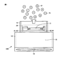
- FIG. 1 is a side view showing a schematic configuration of an electric device 100 including an ion generation device 26 according to Embodiment 1 of the present invention.
- the electric device 100 may be, for example, an ion generator, an air conditioner, a dehumidifier, a humidifier, an air cleaner, a fan heater, or other devices.
- the electrical device 100 is a device that is preferably used to adjust air in a house, a building, a hospital room, a car cabin, an airplane cabin, or a ship vessel.
- the electrical device 100 includes an ion generator 26, a blower 16, and ducts 12 and 15.
- the ducts 12 and 15 are hollow, and the air passage 10 through which air flows is formed by the internal spaces of the ducts 12 and 15 communicating with each other.
- the air blower 16 is provided at the opening of the duct 12 and forms an air flow in the air passage 10.
- the air blower 16 may be a sirocco fan, a cross flow fan, or another fan.
- the ion generator 26 is disposed inside the duct 15.
- the ion generator 26 may be configured to be integrated into the electric device 100.
- the ion generator 26 may be provided so as to be detachable from the electric device 100.
- the ion generator 26 can be made to have a replaceable specification, so that maintenance of the electric device 100 is facilitated.
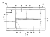
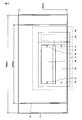
- FIG. 2 is a plan view showing the configuration of the ion generator 26 of the first embodiment.
- FIG. 3 is a side view showing the ion generator 26 as seen from the direction indicated by the arrow III in FIG.
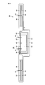
- FIG. 4 is a side view showing the ion generator 26 as seen from the direction indicated by the arrow IV in FIG.
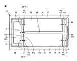
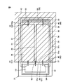
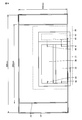
- FIG. 5 is a plan view showing the internal structure of the ion generator 26 of the first embodiment.
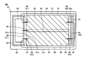
- FIG. 6 is a cross-sectional view of the ion generator 26 along the line VI-VI shown in FIG. With reference to FIGS. 2 to 6, the structure of the ion generator 26 of the present embodiment will be described in detail.
- the ion generator 26 includes an outer case 31, a discharge electrode 40, an induction electrode (counter electrode) 45, a base material 50, a high voltage generation circuit unit 53, a substrate support case 54, and a substrate support.
- a case 55, a wiring 56 and a wiring 57 are mainly provided.
- the discharge electrode 40 includes a first needle-like electrode 41, a second needle-like electrode 42, a third needle-like electrode 43, and a fourth needle-like electrode 44.
- Each of the first to fourth needle-like electrodes 41 to 44 is formed in a needle shape, extends linearly, and has a needle tip with a sharpened tip.
- the first to fourth needle-like electrodes 41 to 44 are arranged in the same plane so that the extending directions of the respective electrodes are parallel to each other.
- the first acicular electrode 41 and the third acicular electrode 43 are arranged side by side with an interval in a direction orthogonal to the extending direction.
- the 2nd discharge electrode 42 and the 4th acicular electrode 44 are arrange
- the first needle-like electrode 41 and the second needle-like electrode 42 are arranged to face each other with a distance in the extending direction.
- the needle tip of the first needle electrode 41 and the needle tip of the second needle electrode 42 face each other.
- the central axis of the first acicular electrode 41 and the central axis of the second acicular electrode 42 are located on the same straight line.
- the third acicular electrode 43 and the fourth acicular electrode 44 are arranged to face each other with a distance in the extending direction.
- the needle tip of the third needle electrode 43 and the needle tip of the fourth needle electrode 44 face each other.
- the central axis of the third acicular electrode 43 and the central axis of the fourth acicular electrode 44 are located on the same straight line.
- the induction electrode 45 is disposed between the first acicular electrode 41 and the third acicular electrode 43.
- the induction electrode 45 is disposed away from both the first needle-like electrode 41 and the third needle-like electrode 43.
- the induction electrode 45 is provided at a position where the distance between the first acicular electrode 41 and the induction electrode 45 and the distance between the third acicular electrode 43 and the induction electrode 45 are equal to each other. Yes.
- the induction electrode 45 is also provided at a position where the distance between the second acicular electrode 42 and the induction electrode 45 and the distance between the fourth acicular electrode 44 and the induction electrode 45 are equal to each other. ing.
- the induction electrode 45 By providing the induction electrode 45 in the middle between the first needle-like electrode 41 and the third needle-like electrode 43, the induction electrode 45 is located farthest from both the first and third needle-like electrodes 41, 43. And the amount of ions recovered by the induction electrode 45 and disappearing can be reduced.
- the first to fourth needle-like electrodes 41 to 44 generate ions by discharge.
- the first acicular electrode 41 and the fourth acicular electrode 44 generate positive ions.
- the second acicular electrode 42 and the third acicular electrode 43 generate negative ions.
- the first acicular electrode 41 and the third acicular electrode 43 generate ions having different polarities, and the second acicular electrode 42 and the fourth acicular electrode 44 have different polarities. Is generated.
- the first acicular electrode 41 and the second acicular electrode 42 generate ions having different polarities, and the third acicular electrode 43 and the fourth acicular electrode 44 have different polarities. Is generated.
- first to fourth needle-shaped electrodes 41 to 44 two needle-shaped electrodes arranged adjacent to each other or facing each other generate ions of different polarities.
- the first to fourth needle-like electrodes 41 to 44 are arranged so that the generated positive ions and negative ions are easily mixed.
- the first to fourth needle-like electrodes 41 to 44 have an air flow relative to the first to fourth needle-like electrodes 41 to 44. Even if the air path is branched downstream (downstream), positive ions and negative ions can be supplied to each branch duct in a balanced manner, and both high-concentration positive ions and negative ions are supplied to the indoor space. Can release mixed air.
- the high voltage generation circuit 53 generates a high voltage to be applied to the first to fourth needle electrodes 41 to 44.
- a positive high voltage is applied to the first needle electrode 41 and a negative high voltage is applied to the third needle electrode 43
- a corona discharge is generated between the discharge electrode and the induction electrode 45.
- Positive ions and negative ions are generated.
- a negative high voltage is applied to the second acicular electrode 42 and a positive high voltage is applied to the fourth acicular electrode 44
- a corona discharge is generated between the discharge electrode and the induction electrode 45.
- negative ions and positive ions are generated.
- the base material 50 has the discharge electrode 40 mounted thereon.
- the base material 50 includes a substrate 51 as a first base material and a substrate 52 as a second base material as separate different base materials.
- the substrate 51 and the substrate 52 are provided to face each other.
- the substrate 51 has one surface 51a and the other surface 51b, and the substrate 52 has one surface 52a.
- the substrates 51 and 52 are arranged so that the surface 51a and the surface 52a face each other.
- the first acicular electrode 41 and the third acicular electrode 43 are mounted on the substrate 51.
- the first needle-like electrode 41 and the third needle-like electrode 43 are fixed to the substrate 51 so that the respective needle tips protrude from the surface 51a.
- the second acicular electrode 42 and the fourth acicular electrode 44 are mounted on the substrate 52.
- the second needle-like electrode 42 and the fourth needle-like electrode 44 are fixed to the substrate 52 such that the respective needle tips protrude from the surface 52a.
- the high voltage generation circuit unit 53 is provided on the other surface 51 b of the substrate 51.
- the substrate support case 54 is provided so as to support the substrate 51 and cover the high voltage generation circuit unit 53.
- the substrate support case 54 has a function as a first housing that accommodates the high voltage generation circuit unit 53 and the substrate 51.
- the substrate support case 55 is provided to support the substrate 52.
- the substrate support case 54 has a function as a housing that accommodates the substrate 52.
- the substrate 51 is formed with a via electrode extending in the thickness direction of the substrate 51 and an electrode pattern extending in a plane direction orthogonal to the thickness direction.
- These via electrodes and electrode patterns include a connection member that electrically connects the high voltage generation circuit portion 53 and the first and third needle-like electrodes 41 and 43.
- the wiring 56 is provided as a connection member that electrically connects the high voltage generation circuit portion 53 and the second needle electrode 42.
- the wiring 57 is provided as a connection member that electrically connects the high voltage generation circuit unit 53 and the fourth needle electrode 44.
- the wirings 56 and 57 are high voltage lines having insulation resistance corresponding to the high voltage generated in the high voltage generation circuit unit 53.
- the substrate support case 55 is provided so as to cover the contacts between the second and fourth discharge electrodes 42 and 44 and the wirings 56 and 57 on the substrate 52.
- the second discharge electrode 42 covers both of the two contacts of the second and fourth discharge electrodes 42 and 44 and the wirings 56 and 57
- a case covering the contact point between the fourth discharge electrode 44 and the wiring 57 may be provided separately.
- the outer case 31 is provided as a casing that forms the appearance of the ion generator 26.
- the outer case 31 is integrally formed of a resin material.
- the outer case 31 has substrate housing portions 32 and 33 and rib-like portions 34 to 36 as its constituent parts.
- the exterior case 31 has a rectangular frame shape in which four sides are constituted by the substrate housing portion 32, the rib-like portion 35, the substrate housing portion 33, and the rib-like portion 34.
- the outer case 31 has a rectangular plan view having a long side extending along the extending direction of the discharge electrode 40 and a short side extending along a direction orthogonal to the extending direction of the discharge electrode 40. .
- the substrate housing part 32 and the substrate housing part 33 are arranged in parallel at a distance from each other.
- the substrate housing part 32 has a larger volume than the substrate housing part 33.
- the substrate accommodating portion 32 accommodates a substrate 51, a high voltage generation circuit portion 53, and a substrate support case 54.
- a substrate 52 and a substrate support case 55 are accommodated in the substrate accommodating portion 33.
- the exterior case 31 has a function as a second casing that accommodates the substrate support case 54, the substrate 52, and the wiring 56.
- the first acicular electrode 41 and the third acicular electrode 43 extend from the surface 51 a of the substrate 51 to the outside of the outer case 31.
- the second acicular electrode 42 and the fourth acicular electrode 44 extend from the surface 52 a of the substrate 52 to the outside of the outer case 31.
- a protective cover that prevents direct contact with the needle tips of the first to fourth needle-like electrodes 41 to 44 may be provided.
- the first and third acicular electrodes 41 and 43, the induction electrode 45, the substrate 51, the high voltage generation circuit unit 53, and the substrate support case 54 constitute a power supply unit.
- substrate support case 55 comprise the electrode unit.
- Both the substrate 51 on which the first and third needle-like electrodes 41 and 43 are mounted and the substrate 52 on which the second and fourth needle-like electrodes 42 and 44 are mounted are in the outer case 31. Contained. Thus, the first to fourth needle-like electrodes 41 to 44 are made into one unit.
- the exterior case 31 further accommodates a high voltage generation circuit unit 53, an induction electrode 45, and wirings 56 and 57.
- the elements constituting the ion generator 26 are accommodated in the exterior case 31 and integrated. ing. Since the first to fourth needle-like electrodes 41 to 44 are unitized, the positioning accuracy of the first to fourth needle-like electrodes 41 to 44 is improved, and the first to fourth needle-like electrodes 41 to 44 are improved.
- the needle electrodes 41 to 44 are easy to handle.
- the rib-shaped portion 34 and the rib-shaped portion 35 are arranged so as to be parallel to each other at a distance and orthogonal to the substrate accommodating portion 32 and the substrate accommodating portion 33.
- One ends of the substrate housing portion 32 and the substrate housing portion 33 facing each other are connected by a rib-shaped portion 34.
- the other ends of the substrate housing portion 32 and the substrate housing portion 33 facing each other are connected by a rib-like portion 35.
- the rib-shaped portion 36 is disposed in parallel with the rib-shaped portion 34 and the rib-shaped portion 35.
- the rib-shaped portion 36 connects the substrate housing portion 32 and the substrate housing portion 33 to each other between the rib-shaped portion 34 and the rib-shaped portion 35.
- the rib portions 34 to 36 extend linearly from the substrate housing portion 32 along the extending direction of the first needle electrode 41 and the third needle electrode 43.
- the rib portions 34 to 36 extend linearly from the substrate housing portion 33 along the extending direction of the second needle electrode 42 and the fourth needle electrode 44.
- the induction electrode 45 protrudes from the surface 51 a of the substrate 51 toward the inside of the rib-shaped portion 36.
- the leading end portion of the induction electrode 45 is accommodated in the exterior case 31 (rib-shaped portion 36).
- the induction electrode 45 may have a plate shape or a rod shape in addition to the illustrated needle shape.
- the wiring 56 is routed from the substrate housing portion 32 to the substrate housing portion 33 through the inside of the rib-shaped portion 35.
- the wiring 57 is routed from the substrate housing portion 32 toward the substrate housing portion 33 through the inside of the rib-shaped portion 34.
- the wiring 56 is routed so as to pass through one of the rib-like portion 34 and the rib-like portion 35, and the wiring 57 is routed so as to pass either one of the rib-like portion 34 and the rib-like portion 35. Yes.
- a hollow space 38 is formed inside the outer case 31 surrounded by the substrate housing portion 32, the rib-shaped portion 35, the substrate housing portion 33 and the rib-shaped portion 34.
- the space 38 is formed in a shape penetrating the outer case 31 in the direction perpendicular to the paper surface in FIGS. 2 and 5, that is, in the vertical direction in FIGS. 3, 4 and 6.
- the exterior case 31 has an outer surface 31 s, and a part of the outer surface 31 s constitutes a first wall surface 37 and a second wall surface 39 that faces the first wall surface 37.
- the first wall surface 37 is formed in the substrate housing portion 32, and the second wall surface 39 is formed in the substrate housing portion 33.
- the first wall surface 37 and the second wall surface 39 constitute a part of the periphery of the space 38.
- the first wall surface 37 and the second wall surface 39 define a space 38 between the substrate housing portions 32 and 33.
- the space 38 is formed between the first wall surface 37 and the second wall surface 39.
- a pair of first wall surface 37 and second wall surface 39 facing each other is provided facing the space 38.
- the tips of the first to fourth needle electrodes 41 to 44 extending from the substrates 51 and 52 are arranged in the space 38.
- the needle tips of the first needle-like electrode 41 and the third needle-like electrode 43 protrude from the first wall surface 37 to the outside of the outer case 31 and are arranged side by side in the space 38.
- the needle tips of the second needle-like electrode 42 and the fourth needle-like electrode 44 protrude from the second wall surface 39 to the outside of the outer case 31 and are arranged side by side in the space 38.
- the needle tips of the first needle-like electrode 41 and the second needle-like electrode 42 are disposed in the space 38 between the rib-like portion 34 and the rib-like portion 36, and the third needle-like electrode 43 and the fourth needle-like electrode 43
- the needle tip of the needle electrode 44 is disposed in a space 38 between the rib-like portion 36 and the rib-like portion 35.
- the rib-shaped portion 36 partitions the first and third needle-shaped electrodes 41 and 43 that generate ions having different polarities, and similarly partitions the second and fourth needle-shaped electrodes.
- the rib-like portion 36 has a function as a partition plate that partitions between two adjacent needle-like electrodes.
- the rib-shaped portion 36 constitutes a part of the outer case 31 and is formed of an insulating resin material. Since the rib-like portion 36 spatially blocks between the two needle-like electrodes that generate ions having different polarities, it is possible to suppress neutralization of positive ions and negative ions having different polarities to reduce the ion concentration. Yes.
- the first wall surface 37 is formed with an opening that penetrates the outer case 31 in the thickness direction, and the opening communicates with the internal space of the substrate housing portion 32 and the space 38.
- the first needle-like electrode 41 and the third needle-like electrode 43 are disposed so as to penetrate the opening formed in the first wall surface 37 and project the tip into the space 38.
- An opening that penetrates the outer case 31 in the thickness direction is formed in the second wall surface 39, and the opening communicates the internal space of the substrate housing portion 33 with the space 38.
- the second needle-like electrode 42 and the fourth needle-like electrode 44 are disposed so as to penetrate the opening formed in the second wall surface 39 and project the tip into the space 38.
- Air is ventilated through the space 38.
- the outer case 31 defines a part of the air flow path. Ions generated by the discharge electrode 40 are transported by air flowing through the space 38.
- the space 38 constitutes a part of an air passage through which a gas for transporting ions generated by the first to fourth acicular electrodes 41 to 44 flows.
- the first wall surface 37 and the second wall surface 39 that define the outer edge of the space 38 constitute a part of the air path.
- the air flowing through the space 38 is ventilated in the direction perpendicular to the paper surface in FIGS. 2 and 5, that is, in the vertical direction in FIGS. 3, 4 and 6.
- the first to fourth needle-like electrodes 41 to 44 are arranged on the same plane perpendicular to the air flow direction in the space 38.
- the first to fourth needle-like electrodes 41 to 44 extend in a direction orthogonal to the direction of air flow in the space 38 and are arranged in parallel to each other.
- the space 38 defined by the outer case 31 of the ion generator 26 constitutes a part of the air passage 10 shown in FIG.
- the space 38 communicates with a part of the air passage 10 formed by the duct 15.
- the blower 16 blows gas into the space 38 included in the air passage 10. Air flowing through the air passage 10 in the duct 15 is passed through the space 38.
- the air flowing through the space 38 is vented in the upward direction in FIG.
- the electric device 100 is provided. Positive ions P and negative ions N (see FIG. 1) generated by the first to fourth needle-like electrodes 41 to 44 are discharged from a blow-out opening in which the duct 15 opens to the outside.
- Ions generated by the first to fourth needle-like electrodes 41 to 44 arranged in parallel in the air passage 10 are transported by air and diffused over a wide area, and high-concentration positive ions and negative ions are spread over a wide range. It comes to exist.
- the ion generator 26 further includes a power supply connector 46.
- the power feeding connector 46 is provided in the board housing portion 32 that houses the high voltage generation circuit portion 53.
- the power supply connector 46 is provided as a power supply unit for supplying power to the high voltage generation circuit unit 53.
- FIG. 7 is a circuit diagram showing a configuration of the ion generator 26 of the first embodiment.
- the ion generator 26 in addition to the first to fourth acicular electrodes 41 to 44 and the induction electrode 45, the ion generator 26 includes terminals T1 and T2, a booster circuit 90, a booster transformer 91, and diodes 92 and 93. , Capacitors 94 and 95.
- the step-up circuit 90, step-up transformer 91, diodes 92 and 93, and capacitors 94 and 95 are included in the configuration of the high voltage generation circuit unit 53 shown in FIG.
- the booster circuit 90 includes a diode, a resistance element, an NPN bipolar transistor, and the like as appropriate.
- Step-up transformer 91 includes a primary winding 91a and a secondary winding 91b.
- the diodes 92 and 93 and the capacitors 94 and 95 are provided for rectification.
- One end of the secondary winding 91b is electrically connected to the first to fourth needle electrodes 41 to 44.
- the other end of the secondary winding 91b is electrically connected to the induction electrode 45.
- the step-up transformer 91 generates a positive or negative high voltage applied to each of the first to fourth needle-like electrodes 41 to 44.
- a positive high voltage pulse is applied to the first needle electrode 41 and the fourth needle electrode 44 via the diode 92, and a negative voltage is applied via the diode 93.
- a high voltage pulse is applied to the second acicular electrode 42 and the third acicular electrode 43.
- corona discharge is generated between the needle tips of the first to fourth needle-like electrodes 41 to 44 and the induction electrode 45, and the first needle-like electrode 41 and the fourth needle-like electrode 44 are positive ions.
- the second acicular electrode 42 and the third acicular electrode 43 generate negative ions.
- a single step-up transformer 91 can apply a high voltage to each of the first to fourth needle-like electrodes 41 to 44, and the number of high voltage generation circuits can be kept to a minimum. It is possible to reduce the manufacturing cost of the ion generator 26 and to reduce the power consumption of the ion generator 26. By reducing the number of induction electrodes 45 in accordance with the number of high voltage generation circuits, the efficiency of ion generation can be improved, and ions generated by the first to fourth needle-like electrodes 41 to 44 can be induced. It is possible to suppress the reduction of the ion concentration by being recovered by the above, and it is possible to generate a higher concentration of ions.
- a positive ion is a cluster ion in which a plurality of water molecules are attached around a hydrogen ion (H + ), and is represented as H + (H 2 O) m (m is an arbitrary integer of 0 or more).
- a negative ion is a cluster ion in which a plurality of water molecules are attached around an oxygen ion (O 2 ⁇ ), and is represented as O 2 ⁇ (H 2 O) n (n is an arbitrary integer of 0 or more).
- FIG. 8 is a schematic diagram illustrating a first example of the relationship between the ion generator 26 and the air passage 10 according to the first embodiment.
- FIG. 9 is a schematic diagram illustrating a second example of the relationship between the ion generator 26 and the air passage 10 according to the first embodiment.
- FIG. 10 is a schematic diagram illustrating a third example of the relationship between the ion generator 26 and the air passage 10 according to the first embodiment.
- FIG. 11 is a schematic diagram illustrating a fourth example of the relationship between the ion generator 26 and the air passage 10 according to the first embodiment.
- the hatched portion indicates the air passage 10.
- the air passage 10 formed in the duct 15 of the electric device 100 includes the space 38 defined by the outer case 31 of the ion generator 26.
- the outer shape of the air passage 10 and the outer shape of the space 38 may be formed to be equal. That is, a configuration in which all of the air passing through the duct 15 passes through the space 38 may be adopted.
- the outer shape of the air passage 10 may be larger than the outer shape of the space 38, and typically, the outer shape of the air passage 10 may be larger than the outer shape of the exterior case 31. In other words, only a part of the air passing through the duct 15 may pass through the space 38.
- the shape of the outer case 31, that is, the shape of the space 38 may be formed in accordance with the shape of the duct 15.
- the shape of the space 38 is also horizontally long by changing the shape of the exterior case 31, and all of the air passing through the duct 15 is formed. May be configured to pass through the space 38.
- the shape of the space 38 is changed to a vertically long shape by changing the shape of the outer case 31, and all of the air passing through the duct 15 is formed. It may be configured to pass through the space 38.
- the ion generator 26 that can supply high-concentration ions suitable for each air passage size can be produced at a lower cost.
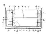
- FIG. 12 is a plan view showing the internal structure of the ion generator 26 of the second embodiment.
- the induction electrode 45 is provided on the other surface 51 b side with respect to the substrate 51. ing.
- the induction electrode 45 is configured by a wiring pattern of the high voltage generation circuit unit 53. If the induction electrode 45 is formed by a printed pattern on the substrate 51, the number of parts can be reduced and the processing cost can be reduced as compared with the configuration in which the pin-like induction electrode 45 is provided.
- FIG. 13 is a plan view showing the internal structure of the ion generator 26 of the third embodiment.
- the ion generator 26 of Embodiment 1 shown in FIG. 5 has a configuration in which the needle tips of the first to fourth needle-like electrodes 41 to 44 protrude into the space 38.
- the first to fourth needle-like electrodes 41 to 44 may be arranged such that the needle tips are present in the outer case 31.
- two holes opened in the first wall surface 37 and two holes opened in the second wall surface 39 may be formed.
- ions generated by the first and third needle-like electrodes 41 and 43 are released into the space 38 from the hole opened in the first wall surface 37.
- Ions generated in the second and fourth needle-like electrodes 42 and 44 are released into the space 38 from the hole opened in the second wall surface 39.
- the ions released into the space 38 are transported by the flow of air passing through the space 38 and supplied to the indoor space.
- FIG. 14 is a plan view showing the internal structure of the ion generator 26 of the fourth embodiment.
- the ion generator 26 according to Embodiment 1 shown in FIG. 5 includes first to fourth needle-like electrodes 41 to 44 protruding into the space 38.
- one first needle-like electrode 41 projecting from the first wall surface 37 of the outer case 31 to the space 38 and one second needle-like electrode projecting from the second wall surface 39 to the space 38. It is good also as a structure provided with the electrode 42.
- the first and second needle-like electrodes 41 and 42 are arranged at intermediate positions between the rib-like portions 34 and 35, and the outer case 31 does not have the rib-like portion 36.
- the induction electrode 45 is disposed so that the needle tip protrudes into the space 38 at a position close to the rib-like portion 35 with respect to the first needle-like electrode 41.
- FIG. 15 is a plan view showing the internal structure of the ion generator 26 of the fifth embodiment.
- the outer case 31 is provided so as to surround the space 38, and there are a plurality of needle-like electrodes that discharge ions from both sides of the first wall surface 37 and the second wall surface 39 facing each other. It was provided.
- the first wall surface 37 and the second wall surface 39 may be formed as the same wall surface facing the space 38. That is, as shown in FIG. 15, the planar first wall surface 37 and the planar second wall surface 39 form the same plane.
- the first to fourth needle-like electrodes 41 to 44 protrude from the same plane and are exposed in the space 38.
- the electrode unit includes one electrode unit including the second needle-like electrode 42 (left side in FIG. 15) and the other electrode unit including the fourth needle-like electrode 44 (right side in FIG. 15). And divided into two.
- One high voltage generation circuit unit 53 provided in the power supply unit is electrically connected to the second needle electrode 42 via a wiring 56, and is connected to the fourth needle electrode 44 via a wiring 57. Electrically connected.
- the induction electrode 45 is configured by a wiring pattern of the high voltage generation circuit unit 53.
- FIG. 16 is a plan view showing the internal structure of the ion generator 26 of the sixth embodiment. Compared to the ion generator 26 of the fifth embodiment shown in FIG. 15, in the ion generator 26 of the sixth embodiment shown in FIG. 16, one first needle electrode 41 is mounted on the substrate 51. The third acicular electrode 43 is not provided. A first needle electrode 41 and an induction electrode 45 mounted on the substrate 51 are provided so as to protrude from the first wall surface 37 to the space 38.
- the first needle electrode 41 may be configured to release either positive ions or negative ions.
- At least one of the second and fourth acicular electrodes 42 and 44 generates ions having a polarity different from the ions generated by the first acicular electrode 41.
- both the second and fourth needle-shaped electrodes 42 and 44 may generate negative ions, or the second and fourth needle-shaped electrodes.
- One of the electrodes 42 and 44 may generate negative ions and the other may generate positive ions.
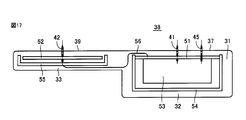
- FIG. 17 is a plan view showing the internal structure of the ion generator 26 of the seventh embodiment.
- the power supply unit is provided with one first needle-like electrode 41
- the electrode unit is provided with one third needle-like electrode 43. ing.
- the first and second needle-like electrodes 41, 42 protrude into the space 38 from the first wall surface 37 and the second wall surface 39 on the same plane.
- the high voltage generation circuit unit 53 included in the power supply unit and the second needle electrode 42 included in the electrode unit are electrically connected via a wiring 56.
- the ion generator 26 includes a first needle electrode 41 as a first discharge electrode, a second needle electrode 42 as a second discharge electrode, and a first base material on which the first needle electrode 41 is mounted. And a substrate 52 as a second base material on which the second acicular electrode 42 is mounted.
- the first acicular electrode 41 and the second acicular electrode 41 each generate ions by discharge.
- the substrate 52 is provided as a separate configuration different from the substrate 51.
- the ion generator 26 also includes a high voltage generation circuit unit 53 that generates a high voltage to be applied to the first needle electrode 41 and the second needle electrode 42, a high voltage generation circuit unit 53, and a second voltage generator circuit unit 53.
- the high voltage generated by the high voltage generation circuit unit 53 is applied to the first and second needle-like electrodes 41, 42, whereby the first and second needle-like electrodes 41, 42 are High concentration of ions can be generated.
- the first acicular electrode 41 and the second acicular electrode 42 are mounted on separate substrates 51 and 52, and the second acicular electrode 42 is electrically connected to the high voltage generation circuit unit 53 via a wiring 56. Since the first needle-like electrode 41 and the second needle-like electrode 42 can be arranged at spatially separated positions, the ions can be released to a wider range, The diffusion of the generated ions can be promoted to suppress a decrease in ion concentration.
- each element constituting the ion generator 26, in particular, the high voltage elements including the first and second needle-like electrodes 41 and 42 and the high voltage generation circuit unit 53 are all accommodated in the outer case 31 and integrated. Since it is provided as one unit, the handleability of the ion generator 26 is improved, and the user can easily handle the ion generator 26. Further, the high voltage generation circuit unit 53 is accommodated in the substrate support case 54, the substrate support case 54 is accommodated in the exterior case 31, and the high voltage generation circuit unit 53 is accommodated in the double case. . By protecting the high voltage generation circuit unit 53 in a double manner, it is possible to prevent a user handling the ion generation device 26 from directly touching the high voltage generation circuit unit 53, thereby improving the safety of the ion generation device 26. Can do.
- the exterior case 31 has an outer surface 31s, and a gas carrying ions generated by the first needle-like electrode 41 and the second needle-like electrode 42 flows in a part of the outer surface 31s. It faces a hollow space 38 that constitutes a part of the air passage 10, the tip of the first needle electrode 41 protrudes into the space 38, and the tip of the second needle electrode 42 faces the space 38. Protruding to In this way, ions are generated at the needle tips of the first and second needle-like electrodes 41, 42 protruding into the space 38, and the generated ions are carried by the gas flowing through the space 38. Therefore, it is possible to realize the ion generator 26 that can efficiently discharge a high concentration of ions.
- the first needle-like electrode 41 and the second needle-like electrode 42 protrude from the first and second wall surfaces 37 and 39 constituting the same surface facing the space 38 into the space 38. In this way, when a plane having a large area constitutes the space 38, high-concentration ions can be emitted over a wide range.
- the first acicular electrode 41 and the second acicular electrode 42 protrude into the space 38 from each of a pair of first wall surface 37 and second wall surface 39 facing the space 38 and facing each other. .
- the first acicular electrode 41 and the second acicular electrode 42 that generate ions of different polarities can be arranged apart from each other, and positive ions and negative ions are diffused over a wider range. be able to.
- it is possible to suppress a decrease in ion concentration due to neutralization of the generated positive ions and negative ions or recovery of ions to the different polarity electrode it is possible to generate ions with a higher concentration.
- the space 38 is provided in a shape penetrating the exterior case 31, ions generated inside the space 38 can be diffused at an early stage, and the reduction in ion concentration due to neutralization of positive ions and negative ions is further suppressed. Can do.
- the tip of the first needle electrode 41 and the tip of the second needle electrode 42 face each other.
- the 1st acicular electrode 41 and the 2nd acicular electrode 42 are arrange
- the wiring 56 is a high voltage line having insulation resistance corresponding to a high voltage generated in the high voltage generation circuit unit 53.
- the wiring 56 which is a high-voltage line, is accommodated in the outer case 31, and the outer case 31 forms a path for routing the wiring 56, so that a user who handles the ion generator 26 has a high pressure. Since it is possible to avoid touching the line directly, the safety of the ion generator 26 can be further improved.
- the electric device 100 includes the ion generator 26 according to any one of the above aspects and the blower 16 that blows a gas that conveys ions generated by the discharge electrodes 40 of the ion generator 26.
- the electric device 100 including the ion generator 26 that can generate ions with a high concentration in a wide range and is excellent in handling and safety. Since the ion generator 26 is provided as one unit, when the ion generator 26 is detachable from the electric device 100, the ion generator 26 can be easily replaced.
- FIG. 18 is a schematic diagram illustrating a state in which the ion generator 26 according to the first embodiment is disposed in the air passage 10.
- a duct 15 for forming the air passage 10 is provided in the housing 14 corresponding to the casing of the electric device 100, and the inside of the duct 15 will be described with reference to FIGS.
- the ion generator 26 of the first embodiment is arranged.
- the housing 14 has a width of 300 mm and a height of 150 mm
- the duct 15 has a width of 245 mm and a height of 150 mm. Air was blown into the duct 15 by a cross flow fan (not shown) so that the discharge electrode 40 would have a flow velocity of 5 m / s.
- the first to fourth needle-like electrodes 41 to 44 were provided so that the needle tips protruded from the outer case 31 by 9.5 mm, respectively.
- the distance between the needle tip of the first needle electrode 41 and the needle tip of the second needle electrode 42, and the distance between the needle tip of the third needle electrode 43 and the needle tip of the fourth needle electrode 44 Each distance was 101 mm.
- the interval was 37 mm.
- the duct 15 is arranged so that air flows in the direction perpendicular to the paper surface of FIG. 18, and the ion generating device 26 places the outer case 31 in the duct 15 so that the air flowing in the duct 15 penetrates the space 38. It was placed upright.
- the first to fourth needle-like electrodes 41 to 44 are arranged so as to extend in a direction perpendicular to the air flow direction in the duct 15.
- the ion generator 26 of Example 1 was disposed in the duct 15 so as to be offset in the height direction. Specifically, it was arranged so that the axis connecting the first needle electrode 41 and the second needle electrode 42 was located at a position 18.5 mm from the inner wall on the bottom side of the duct 15.
- FIG. 19 is a schematic diagram showing a state in which the ion generator 26 of Example 2 is arranged in the air passage 10.
- the ion generator 26 of Example 2 has the configuration in which the ion generator 26 of Embodiment 2 described with reference to FIG. 12, that is, the induction electrode 45 is provided in a high voltage generation circuit unit 53 in a wiring pattern. It was. As shown in FIG. 19, the ion generator 26 of Example 2 was similarly arrange
- FIG. 20 is a schematic diagram showing a state in which the ion generator 226 of Comparative Example 1 is arranged in the air passage 10.
- the ion generator 226 of Comparative Example 1 includes a first acicular electrode 241, a second acicular electrode 242, a third acicular electrode 243, a fourth acicular electrode 244, which are discharge electrodes, and each discharge electrode. And four annular induction electrodes. A positive or negative high voltage is applied to each of the first to fourth needle-like electrodes 241 to 244 to generate positive ions or negative ions, respectively.
- Such an ion generator 226 of Comparative Example 1 was placed in the duct 15 having the same shape as in FIG. 18 at a position on the bottom surface side in the height direction in the duct 15.
- the first to fourth needle-like electrodes 241 to 244 were provided so that the respective needle tips protrude into the duct 15 by 7 mm.
- Table 1 summarizes the integrated values of the measured values of the ion concentration in Comparative Example 1 and Example 1 with Comparative Example 1 as 100%.
- the ion concentration was measured at a position 350 mm away from the electrode on the downstream side (downstream side) of the air flow through the duct 15.
- the measurement points were 3 points at 100 mm intervals in the width direction of the duct 15 and 3 points at 60 mm intervals in the height direction, for a total of 9 points in a lattice shape.
- Example 1 As shown in Table 1, the integrated value of the ion concentration at 9 measurement points in Example 1 was 318% of Comparative Example 1. From this result, the ion generator 26 of Example 1 can supply more positive ions and negative ions than the ion generator 226 of Comparative Example 1, and a sufficient number of positive ions in the vicinity of the outlet of the ion generator 26. It was confirmed that ions and negative ions could be supplied.
- Table 2 shows the ion concentration at one measurement point at the center in the width direction of the inner wall on the bottom surface side of the duct 15, which is 350 mm away from the electrode on the downstream side (leeward side) of the air flow flowing through the duct 15 in Examples 1 and 2.
- Example 1 is summarized as 100%.
- Example 2 As shown in Table 2, the positive ion concentration at one measurement point in Example 2 was 101% of Example 1, and the negative ion concentration was 103% of Example 1. From this result, it was confirmed that in Example 2 in which the induction electrode 45 was formed by the wiring pattern, a sufficient amount of ions equivalent to or higher than that of the ion generator 26 of Example 1 could be supplied.
- FIG. 21 is a schematic diagram showing an ion concentration distribution on the downstream side of the ion generator 26 of the first embodiment.
- FIG. 22 is a schematic diagram showing an ion concentration distribution on the downstream side of the ion generator 26 of Comparative Example 1.
- the lower one of the positive ion and the negative ion concentration measured at a position 350 mm from the electrode on the downstream side (downstream side) of the air flow flowing through the duct 15. (Ie, the distribution of the lower ion concentration when positive and negative ions coexist) is shown as a graph.
- the vertical axis indicates the height direction coordinate of the duct 15
- the horizontal axis indicates the width direction coordinate of the duct 15
- the normalized ion concentration is shown by the shading of the graph.
- the center of the duct 15 in the width direction and the inner wall on the bottom side in the height direction are set to 0 of the coordinate axis.
- Comparative Example 1 shown in FIG. 22 a high ion concentration is obtained near the center of the bottom surface of the duct 15 provided with four needle-shaped electrodes, but the ion concentrations near the ceiling of the duct 15 and on the left and right in the width direction are small. The range in which high concentrations of ions are present was small.
- Example 1 shown in FIG. 21 a region where positive ions and negative ions coexist in a wide range, and the ion concentration in the vicinity of the coordinate axis 0 is compared with Example 1 than Comparative Example 1. It can be seen that there is a larger region where high-concentration positive ions and negative ions coexist. Therefore, it was shown that the ion generator 26 of Example 1 can supply a sufficient number of positive ions and negative ions, and a high concentration of positive ions and negative ions can exist in a wide range.
Landscapes
- Engineering & Computer Science (AREA)
- Health & Medical Sciences (AREA)
- Veterinary Medicine (AREA)
- Animal Behavior & Ethology (AREA)
- General Health & Medical Sciences (AREA)
- Public Health (AREA)
- Life Sciences & Earth Sciences (AREA)
- Physics & Mathematics (AREA)
- Epidemiology (AREA)
- Plasma & Fusion (AREA)
- Chemical & Material Sciences (AREA)
- Combustion & Propulsion (AREA)
- Mechanical Engineering (AREA)
- General Engineering & Computer Science (AREA)
- Disinfection, Sterilisation Or Deodorisation Of Air (AREA)
Abstract
高濃度のイオンを広範囲に放出できるとともに取扱性に優れたイオン発生装置を提供する。イオン発生装置は、それぞれが放電によりイオンを発生する第1の針状電極(41)および第2の針状電極(42)と、第1の針状電極(41)を搭載している基板(51)と、基板(51)とは異なる基材であって、第2の針状電極(42)を搭載している第2の基材と、第1の針状電極(41)および第2の針状電極(42)に印加するための高電圧を発生する高電圧発生回路部(53)と、高電圧発生回路部(53)と第2の針状電極(42)とを電気的に接続している配線(56)と、高電圧発生回路部(53)および基板(51)を収容している基板支持ケース(54)と、基板支持ケース(54)、基板(52)および配線(56)を収容している外装ケース(31)とを備えている。
Description
本発明は、イオン発生装置および電気機器に関し、特に、複数の針状電極を備えるイオン発生装置と、そのイオン発生装置を用いた電気機器とに関する。
従来、室内の空気の浄化、殺菌または消臭などを行なうために、イオン発生装置が利用されている。イオン発生装置の多くは、コロナ放電により正イオンおよび負イオンを発生させている。
特開2011-60537号公報(特許文献1)には、電源から供給された電力によりプラスイオンを放出する第1の電極と、第1の電極に対し所定の間隔をあけて配置され、電源から供給された電力によりマイナスイオンを放出する第2の電極とを備えており、電源の正端子と第1の電極とが接続されており、電源の負端子と第2の電極とが接続されている、除電装置が開示されている。
一般的にイオン発生装置は、放電によりイオンを発生する放電電極と、放電電極に高電圧を印加するための高電圧発生部とを備えている。放電を長期間に渡って繰り返し行なうと、放電電極に汚れが生じたり劣化したりするため、イオン発生装置は定期的なメンテナンスまたは交換を必要としている。そのため、容易に取扱の可能なイオン発生装置の構造が重要となっている。
本発明は上記の課題に鑑みてなされたものであり、その主たる目的は、高濃度のイオンを広範囲に放出できるとともに取扱性に優れた、イオン発生装置を提供することである。
本発明に係るイオン発生装置は、第1放電電極および第2放電電極と、第1の基材と、第2の基材と、高電圧発生部と、接続部と、第1筺体と、第2筺体とを備えている。第1放電電極および第2放電電極は、それぞれが放電によりイオンを発生する。第1の基材は、第1放電電極を搭載している。第2の基材は、第1の基材とは異なる基材であって、第2放電電極を搭載している。高電圧発生部は、第1放電電極および第2放電電極に印加するための高電圧を発生する。接続部は、高電圧発生部と第2放電電極とを電気的に接続している。第1筺体は、高電圧発生部および第1の基材を収容している。第2筺体は、第1筺体、第2の基材および接続部を収容している。
上記イオン発生装置において好ましくは、第2筺体は、外表面を有している。外表面の一部は、中空空間に面している。中空空間は、第1放電電極および第2放電電極が発生したイオンを搬送する気体が流れる風路の一部を構成している。第1放電電極の先端は、中空空間へ突出している。第2放電電極の先端は、中空空間へ突出している。
上記イオン発生装置において好ましくは、第1放電電極と第2放電電極とは、中空空間に面する同一の壁面から中空空間へ突出している。
上記イオン発生装置において好ましくは、第1放電電極と第2放電電極とは、中空空間に面し互いに対向する一対の壁面の各々からそれぞれ中空空間へ突出している。好ましくは、第1放電電極の先端と第2放電電極の先端とが互いに向かい合っている。
上記イオン発生装置において好ましくは、接続部は、高電圧発生部で発生する高電圧に対応した絶縁耐性を有する高圧線である。
本発明に係る電気機器は、上記のいずれかの局面のイオン発生装置と、イオン発生装置の放電電極が発生したイオンを搬送する気体を送風するために構成された送風装置とを備えている。
本発明によると、高濃度のイオンを広範囲に放出できるとともに取扱性に優れたイオン発生装置を実現することができる。
以下、図面に基づいてこの発明の実施の形態を説明する。なお、以下の図面において、同一または相当する部分には同一の参照番号を付し、その説明は繰返さない。
(実施の形態1)
図1は、本発明の実施の形態1におけるイオン発生装置26を備える電気機器100の概略構成を示す側面図である。電気機器100は、たとえばイオン発生機、空気調和機、除湿機、加湿器、空気清浄機、ファンヒータまたはその他の機器であってもよい。電気機器100は、家屋の室内、ビルの一室、病院の病室、自動車の車室内、飛行機の機内または船の船舶内などの空気を調節するために、好適に用いられる機器である。
図1は、本発明の実施の形態1におけるイオン発生装置26を備える電気機器100の概略構成を示す側面図である。電気機器100は、たとえばイオン発生機、空気調和機、除湿機、加湿器、空気清浄機、ファンヒータまたはその他の機器であってもよい。電気機器100は、家屋の室内、ビルの一室、病院の病室、自動車の車室内、飛行機の機内または船の船舶内などの空気を調節するために、好適に用いられる機器である。
図1に示すように、電気機器100は、イオン発生装置26と、送風装置16と、ダクト12,15とを備えている。ダクト12,15は中空であり、ダクト12,15の内部空間が互いに連通されることにより、空気が流れる風路10が形成されている。送風装置16は、ダクト12の開口部に設けられており、風路10内に空気の流れを形成する。送風装置16は、シロッコファン、クロスフローファンまたはその他のファンであってもよい。
イオン発生装置26は、ダクト15の内部に配置されている。イオン発生装置26は、電気機器100に一体に組み込まれた構成であってもよい。またはイオン発生装置26は、電気機器100に対して取り外し可能に設けられてもよく、この場合、イオン発生装置26を交換可能な仕様にできるので、電気機器100のメンテナンスが容易になる。
図2は、実施の形態1のイオン発生装置26の構成を示す平面図である。図3は、図2中の矢印IIIに示す方向から見たイオン発生装置26を示す側面図である。図4は、図2中の矢印IVに示す方向から見たイオン発生装置26を示す側面図である。図5は、実施の形態1のイオン発生装置26の内部構造を示す平面図である。図6は、図5に示すVI-VI線に沿うイオン発生装置26の断面図である。図2~図6を参照して、本実施の形態のイオン発生装置26の構造について詳細に説明する。
実施の形態1のイオン発生装置26は、外装ケース31と、放電電極40と、誘導電極(対向電極)45と、基材50と、高電圧発生回路部53と、基板支持ケース54および基板支持ケース55と、配線56および配線57とを主に備えている。
放電電極40は、第1の針状電極41、第2の針状電極42、第3の針状電極43および第4の針状電極44を含んでいる。第1~第4の針状電極41~44は、それぞれ、針形状に形成されており、直線状に延在するとともに、先端が尖鋭化された針先を有している。第1~第4の針状電極41~44は、それぞれの電極の延びる方向が互いに平行となるように、同一平面内に配置されている。
第1の針状電極41と第3の針状電極43とは、それぞれの延びる方向に対して直交する方向に間隔をあけて、並んで配置されている。第2の放電電極42と第4の針状電極44とは、それぞれの延びる方向に対して直交する方向に間隔をあけて、並んで配置されている。
第1の針状電極41と第2の針状電極42とは、それぞれの延びる方向に距離を設けて、互いに対向して配置されている。第1の針状電極41の針先と、第2の針状電極42の針先とは、互いに向かい合っている。第1の針状電極41の中心軸と第2の針状電極42の中心軸とは、同一直線上に位置している。第3の針状電極43と第4の針状電極44とは、それぞれの延びる方向に距離を設けて、互いに対向して配置されている。第3の針状電極43の針先と、第4の針状電極44の針先とは、互いに向かい合っている。第3の針状電極43の中心軸と第4の針状電極44の中心軸とは、同一直線上に位置している。
誘導電極45は、第1の針状電極41と第3の針状電極43との間に配置されている。誘導電極45は、第1の針状電極41および第3の針状電極43の両方から離れて配置されている。誘導電極45は、第1の針状電極41と誘導電極45との間の距離と、第3の針状電極43と誘導電極45との間の距離とが、互いに等しくなる位置に設けられている。誘導電極45はまた、第2の針状電極42と誘導電極45との間の距離と、第4の針状電極44と誘導電極45との間の距離とが、互いに等しくなる位置に設けられている。誘導電極45を第1の針状電極41と第3の針状電極43との中間に設けることで、第1および第3の針状電極41,43の両方から最も離れた位置に誘導電極45を配置することができ、誘導電極45で回収されて消滅するイオンの量を低減できる。
第1~第4の針状電極41~44は、それぞれが放電によりイオンを発生する。第1の針状電極41と第4の針状電極44とは、正イオンを発生する。第2の針状電極42と第3の針状電極43とは、負イオンを発生する。第1の針状電極41と第3の針状電極43とは、互いに異なる極性のイオンを発生させ、第2の針状電極42と第4の針状電極44とは、互いに異なる極性のイオンを発生させる。第1の針状電極41と第2の針状電極42とは、互いに異なる極性のイオンを発生させ、第3の針状電極43と第4の針状電極44とは、互いに異なる極性のイオンを発生させる。
第1~第4の針状電極41~44のうち、隣接して配置されるまたは互いに向かい合って配置される2つの針状電極は、異なる極性のイオンを発生する。第1~第4の針状電極41~44は、発生する正イオンと負イオンとが混合されやすいように配置されており、たとえば、第1~第4の針状電極41~44に対し空気流れの下流側(風下側)に風路を分岐させたとしても、各々の分岐ダクトにバランスよく正イオンと負イオンとを供給でき、室内空間に高濃度の正イオンと負イオンとの両方が混合された空気を放出できる。
高電圧発生回路部53は、第1~第4の針状電極41~44に印加するための高電圧を発生させる。第1の針状電極41に正の高電圧が印加され、第3の針状電極43に負の高電圧が印加されると、これら放電電極と誘導電極45との間にコロナ放電が発生し、正イオンおよび負イオンが発生する。同様に、第2の針状電極42に負の高電圧が印加され、第4の針状電極44に正の高電圧が印加されると、これら放電電極と誘導電極45との間にコロナ放電が発生し、負イオンおよび正イオンが発生する。
基材50は、放電電極40を搭載している。基材50は、第1の基材としての基板51と、第2の基材としての基板52とを、別々の異なる基材として含んでいる。基板51と基板52とは、互いに対向して設けられている。基板51は一方の表面51aと他方の表面51bとを有しており、基板52は一方の表面52aを有している。表面51aと表面52aとが対面するように、基板51,52は配置されている。
第1の針状電極41および第3の針状電極43は、基板51に搭載されている。第1の針状電極41および第3の針状電極43は、それぞれの針先が表面51aから突出するように、基板51に固定されている。第2の針状電極42および第4の針状電極44は、基板52に搭載されている。第2の針状電極42および第4の針状電極44は、それぞれの針先が表面52aから突出するように、基板52に固定されている。
高電圧発生回路部53は、基板51の他方の表面51bに設けられている。基板支持ケース54は、基板51を支持するとともに、高電圧発生回路部53を覆うように設けられている。基板支持ケース54は、高電圧発生回路部53および基板51を収容する第1筺体としての機能を有している。基板支持ケース55は、基板52を支持するように設けられている。基板支持ケース54は、基板52を収容する筺体としての機能を有している。
基板51には、基板51の厚み方向に延びるビア電極、および、厚み方向に直交する面方向に延びる電極パターンが形成されている。これらビア電極および電極パターンは、高電圧発生回路部53と第1および第3の針状電極41,43との間を電気的に接続する接続部材を含んでいる。配線56は、高電圧発生回路部53と第2の針状電極42の間を電気的に接続する接続部材として設けられている。配線57は、高電圧発生回路部53と第4の針状電極44との間を電気的に接続する接続部材として設けられている。配線56,57は、高電圧発生回路部53で発生する高電圧に対応した絶縁耐性を有している高圧線である。
基板支持ケース55は、基板52における、第2および第4の放電電極42,44と配線56,57との接点を覆うように、設けられている。単一の基板支持ケース55が第2および第4の放電電極42,44と配線56,57との2つの接点の両方を覆っている図5に示す構成に替えて、第2の放電電極42と配線56との接点を覆うケースと、第4の放電電極44と配線57との接点を覆うケースとを、別々に設けてもよい。
外装ケース31は、イオン発生装置26の外観をなす筺体として設けられている。外装ケース31は、樹脂材料により一体に成形されている。外装ケース31は、その構成部位として、基板収容部32,33と、リブ状部34~36とを有している。外装ケース31は、基板収容部32、リブ状部35、基板収容部33およびリブ状部34により四辺が構成される、矩形の枠形状を有している。外装ケース31は、放電電極40の延在方向に沿って延びる長辺と、放電電極40の延在方向に直交する方向に沿って延びる短辺とを有する、矩形の平面視を有している。
基板収容部32および基板収容部33は、互いに距離を隔てて平行に配置されている。基板収容部32は、基板収容部33よりも大きい容積を有している。基板収容部32には、基板51、高電圧発生回路部53および基板支持ケース54が収容されている。基板収容部33には、基板52および基板支持ケース55が収容されている。外装ケース31は、基板支持ケース54、基板52および配線56を収容する、第2筺体としての機能を有している。
第1の針状電極41および第3の針状電極43は、基板51の表面51aから外装ケース31の外部に延出している。第2の針状電極42および第4の針状電極44は、基板52の表面52aから外装ケース31の外部に延出している。図5に示す構成に追加して、安全性を向上させるために、第1~第4の針状電極41~44の針先に直接触れられなくする保護カバーを設けてもよい。
第1および第3の針状電極41,43、誘導電極45、基板51、高電圧発生回路部53および基板支持ケース54は、電源ユニットを構成している。第2および第4の針状電極42,44、基板52および基板支持ケース55は、電極ユニットを構成している。
第1および第3の針状電極41,43を搭載している基板51と、第2および第4の針状電極42,44を搭載している基板52とは、いずれも外装ケース31内に収容されている。これにより、第1~第4の針状電極41~44は、1ユニット化されている。外装ケース31内にはさらに、高電圧発生回路部53、誘導電極45、配線56,57も収容されており、イオン発生装置26を構成する各要素が外装ケース31内に収められて一体化されている。第1~第4の針状電極41~44が1ユニット化されているために、第1~第4の針状電極41~44の位置決め精度が向上されており、また第1~第4の針状電極41~44の取扱が容易とされている。
リブ状部34およびリブ状部35は、互いに距離を隔てて平行に、かつ、基板収容部32および基板収容部33と直交するように配置されている。互いに対向する基板収容部32および基板収容部33の一方端同士が、リブ状部34によって連結されている。互いに対向する基板収容部32および基板収容部33の他方端同士が、リブ状部35によって連結されている。
リブ状部36は、リブ状部34およびリブ状部35と平行に配置されている。リブ状部36は、リブ状部34とリブ状部35との間で、基板収容部32および基板収容部33を互いに連結している。
リブ状部34~36は、基板収容部32から、第1の針状電極41および第3の針状電極43の延在方向に沿って、直線状に延びている。リブ状部34~36は、基板収容部33から、第2の針状電極42および第4の針状電極44の延在方向に沿って、直線状に延びている。
誘導電極45は、基板51の表面51aからリブ状部36の内部に向けて突出している。誘導電極45の先端部は、外装ケース31(リブ状部36)の内部に収容されている。絶縁性の樹脂材料製である外装ケース31内に誘導電極45を収容することにより、誘導電極45で回収されて消滅するイオンの量を低減できる。なお、誘導電極45は、図示された針状の形状のほか、板状または棒状の形状を有していてもよい。
配線56は、基板収容部32からリブ状部35の内部を通って基板収容部33に向かうように配索されている。配線57は、基板収容部32からリブ状部34の内部を通って基板収容部33に向かうように配索されている。配線56は、リブ状部34およびリブ状部35のいずれか一方を通るように配索され、配線57は、リブ状部34およびリブ状部35のいずれか他方を通るように配索されている。
基板収容部32、リブ状部35、基板収容部33およびリブ状部34により囲まれた外装ケース31の内側には、中空の空間38が形成されている。空間38は、図2および図5における紙面垂直方向、すなわち、図3、図4および図6における上下方向に、外装ケース31を貫通する形状に形成されている。
外装ケース31は、外表面31sを有しており、外表面31sの一部は、第1壁面37と、第1壁面37に対向する第2壁面39とを構成している。第1壁面37は基板収容部32に形成されており、第2壁面39は基板収容部33に形成されている。第1壁面37と第2壁面39とは、空間38の周縁の一部を構成している。第1壁面37と第2壁面39とは、基板収容部32,33間の空間38を区画形成している。空間38は、第1壁面37と第2壁面39との間に形成されている。互いに対向する一対の第1壁面37と第2壁面39とは、空間38に面して設けられている。
基板51,52から延出する第1~第4の針状電極41~44の先端部は、空間38に配置されている。第1の針状電極41および第3の針状電極43の針先は、第1壁面37から外装ケース31の外部へ突出して、空間38内に並べて配置されている。第2の針状電極42および第4の針状電極44の針先は、第2壁面39から外装ケース31の外部へ突出して、空間38内に並べて配置されている。第1の針状電極41および第2の針状電極42の針先は、リブ状部34とリブ状部36との間の空間38に配置され、第3の針状電極43および第4の針状電極44の針先は、リブ状部36とリブ状部35との間の空間38に配置されている。
リブ状部36は、互いに極性の異なるイオンを発生する第1および第3の針状電極41,43の間を仕切り、同様に、第2および第4の針状電極の間を仕切っている。リブ状部36は、隣接する二つの針状電極間を仕切る仕切り板としての機能を有している。リブ状部36は、外装ケース31の一部を構成しており、絶縁性の樹脂材料によって形成されている。極性の異なるイオンを発生する二つの針状電極間がリブ状部36で空間的に遮断されるので、極性の異なる正イオンおよび負イオンが中和してイオン濃度が減少することが抑制されている。
第1壁面37には、外装ケース31を厚み方向に貫通する開口部が形成されており、当該開口部は、基板収容部32の内部空間と空間38とを連通している。第1の針状電極41および第3の針状電極43は、第1壁面37に形成された開口部を貫通して、先端を空間38に突出させて配置されている。第2壁面39には、外装ケース31を厚み方向に貫通する開口部が形成されており、当該開口部は、基板収容部33の内部空間と空間38とを連通している。第2の針状電極42および第4の針状電極44は、第2壁面39に形成された開口部を貫通して、先端を空間38に突出させて配置されている。
空間38には、空気が通風される。外装ケース31は、空気の流路の一部を規定している。放電電極40が発生したイオンは、空間38を通過して流れる空気によって搬送される。空間38は、第1~第4の針状電極41~44が発生したイオンを搬送するための気体が流れる風路の一部を構成している。空間38の外縁を規定する第1壁面37および第2壁面39は、風路の一部を構成している。
空間38を流れる空気は、図2および図5における紙面垂直方向、すなわち、図3、図4および図6における上下方向に、通風される。第1~第4の針状電極41~44は、空間38内の空気の流れる方向に対し直交する同一平面上に配置されている。第1~第4の針状電極41~44は、空間38内の空気の流れる方向に対し直交する方向に延びて、互いに平行に配置されている。
イオン発生装置26の外装ケース31により規定される空間38は、図1に示す風路10の一部を構成している。空間38は、ダクト15により形成される一部の風路10に連通している。送風装置16は、風路10に含まれる空間38内に気体を送風する。空間38には、ダクト15内の風路10を流れる空気が通風される。空間38を通過して流れる空気は、図1中の上向き方向に通風される。
空間38を通過して空気が流れることにより、放電電極40が発生したイオンが、空気の流れによって搬送され、図1に示す風路10を経由して吹出口から室内空間に放出される。空間38内に突出した第1~第4の針状電極41~44の風上および風下には、第1~第4の針状電極41~44への通風の妨げとなる構造物を配置しないように、電気機器100は設けられている。第1~第4の針状電極41~44が発生した正イオンPおよび負イオンN(図1参照)は、ダクト15が外部に開口する吹出口から放出される。風路10内に平行に配置された第1~第4の針状電極41~44で発生したイオンは、空気により搬送されて広いエリアに拡散し、高濃度の正イオンおよび負イオンが広範囲に存在するようになる。
イオン発生装置26は、給電コネクタ46をさらに備えている。給電コネクタ46は、高電圧発生回路部53を収容する基板収容部32に設けられている。給電コネクタ46は、高電圧発生回路部53に電力を供給するための給電部として設けられている。
図7は、実施の形態1のイオン発生装置26の構成を示す回路図である。図7に示すように、イオン発生装置26は、第1~第4の針状電極41~44および誘導電極45の他に、端子T1,T2、昇圧回路90、昇圧トランス91、ダイオード92,93、コンデンサ94,95とを備えている。昇圧回路90、昇圧トランス91、ダイオード92,93、コンデンサ94,95は、図5に示す高電圧発生回路部53の構成に含まれている。
昇圧回路90は、ダイオード、抵抗素子およびNPNバイポーラトランジスタなどを適宜含んで構成されている。昇圧トランス91は、一次巻線91aと、二次巻線91bとを含んでいる。ダイオード92,93およびコンデンサ94,95は、整流のために設けられている。二次巻線91bの一端は、第1~第4の針状電極41~44に電気的に接続されている。二次巻線91bの他端は、誘導電極45に電気的に接続されている。
昇圧トランス91は、第1~第4の針状電極41~44のそれぞれに印加される正または負の高電圧を発生する。端子T1,T2間に電圧が印加されると、ダイオード92を介して正の高電圧パルスが第1の針状電極41および第4の針状電極44に印加され、ダイオード93を介して負の高電圧パルスが第2の針状電極42および第3の針状電極43に印加される。これにより、第1~第4の針状電極41~44の針先と誘導電極45との間でコロナ放電が発生し、第1の針状電極41および第4の針状電極44が正イオンを発生し、第2の針状電極42および第3の針状電極43が負イオンを発生する。
1つの昇圧トランス91で第1~第4の針状電極41~44の各々に高電圧を印加することができ、高電圧発生用回路の数を最小限に留めることができるので、部品点数を削減してイオン発生装置26の製造コストを抑制できるとともに、イオン発生装置26の消費電力を低減することができる。高電圧発生用回路の数に合わせて誘導電極45の数を低減することで、イオン発生の効率を向上できるとともに、第1~第4の針状電極41~44で発生したイオンが誘導電極45で回収されてイオン濃度が減少することを抑制でき、より高濃度のイオンを発生することができる。
なお、正イオンは、水素イオン(H+)の周囲に複数の水分子が付随したクラスターイオンであり、H+(H2O)m(mは0以上の任意の整数)と表わされる。負イオンは、酸素イオン(O2
-)の周囲に複数の水分子が付随したクラスターイオンであり、O2
-(H2O)n(nは0以上の任意の整数)と表わされる。正イオンおよび負イオンを放出すると、両イオンが空気中を浮遊するカビ菌やウィルスの周りを取り囲み、その表面上で互いに化学反応を起こす。その際に生成される活性種の水酸化ラジカル(・OH)の作用により、浮遊カビ菌などが除去される。
図8は、実施の形態1のイオン発生装置26と風路10との関係の第1の例を示す模式図である。図9は、実施の形態1のイオン発生装置26と風路10との関係の第2の例を示す模式図である。図10は、実施の形態1のイオン発生装置26と風路10との関係の第3の例を示す模式図である。図11は、実施の形態1のイオン発生装置26と風路10との関係の第4の例を示す模式図である。なお、図8~11において斜線のハッチングを付した部分が、風路10を示している。
上述したように、電気機器100のダクト15内に形成される風路10は、イオン発生装置26の外装ケース31によって規定される空間38を含んでいる。この空間38と風路10との関係としては、たとえば図8に示すように、風路10の外形と空間38の外形とが等しく形成されてもよい。すなわち、ダクト15内を通過する空気の全てが空間38を通過するような構成としてもよい。または、図9に示すように、風路10の外形を空間38の外形よりも大きくし、典型的には風路10の外形を外装ケース31の外形よりも大きくしてもよい。すなわち、ダクト15内を通過する空気の一部のみが空間38を通過するような構成としてもよい。
また、電気機器100が形状または寸法の異なるダクト15を備えている場合、外装ケース31の形状、従って空間38の形状を、ダクト15の形状に合わせて形成してもよい。たとえば図10に示すように、ダクト15が横長形状の風路10を形成する場合、外装ケース31の形状を変更することにより空間38の形状も横長にして、ダクト15内を通過する空気の全てが空間38を通過するような構成としてもよい。図11に示すように、ダクト15が縦長形状の風路10を形成する場合、外装ケース31の形状を変更することにより空間38の形状の縦長にして、ダクト15内を通過する空気の全てが空間38を通過するような構成としてもよい。
本実施の形態によれば、各々の風路サイズに適した高濃度のイオンを供給できるイオン発生装置26を、より安価に作成することが可能となる。
(実施の形態2)
図12は、実施の形態2のイオン発生装置26の内部構造を示す平面図である。図5に示す実施の形態1のイオン発生装置26と比較して、図12に示す実施の形態2のイオン発生装置26では、誘導電極45が基板51に対して他方の表面51b側に設けられている。誘導電極45は、高電圧発生回路部53の配線パターンによって構成されている。誘導電極45を基板51上の印刷パターンで形成すれば、ピン状の誘導電極45を設ける構成と比較して、部品点数を削減できるとともに加工費を抑制することができる。
図12は、実施の形態2のイオン発生装置26の内部構造を示す平面図である。図5に示す実施の形態1のイオン発生装置26と比較して、図12に示す実施の形態2のイオン発生装置26では、誘導電極45が基板51に対して他方の表面51b側に設けられている。誘導電極45は、高電圧発生回路部53の配線パターンによって構成されている。誘導電極45を基板51上の印刷パターンで形成すれば、ピン状の誘導電極45を設ける構成と比較して、部品点数を削減できるとともに加工費を抑制することができる。
(実施の形態3)
図13は、実施の形態3のイオン発生装置26の内部構造を示す平面図である。図5に示す実施の形態1のイオン発生装置26では、第1~第4の針状電極41~44の各々の針先が空間38に突出する構成を備えていた。この構成に替えて、図13に示すように、第1~第4の針状電極41~44は針先が外装ケース31内に存在しているように配置されていてもよく、外装ケース31に、第1壁面37に開口する2つの穴、および、第2壁面39に開口する2つの穴を形成してもよい。この場合、第1および第3の針状電極41,43で発生するイオンは、第1壁面37に開口する穴から空間38に放出される。第2および第4の針状電極42,44で発生するイオンは、第2壁面39に開口する穴から空間38に放出される。空間38に放出されたイオンは、空間38内を通過する空気の流れによって搬送され、室内空間へ供給される。
図13は、実施の形態3のイオン発生装置26の内部構造を示す平面図である。図5に示す実施の形態1のイオン発生装置26では、第1~第4の針状電極41~44の各々の針先が空間38に突出する構成を備えていた。この構成に替えて、図13に示すように、第1~第4の針状電極41~44は針先が外装ケース31内に存在しているように配置されていてもよく、外装ケース31に、第1壁面37に開口する2つの穴、および、第2壁面39に開口する2つの穴を形成してもよい。この場合、第1および第3の針状電極41,43で発生するイオンは、第1壁面37に開口する穴から空間38に放出される。第2および第4の針状電極42,44で発生するイオンは、第2壁面39に開口する穴から空間38に放出される。空間38に放出されたイオンは、空間38内を通過する空気の流れによって搬送され、室内空間へ供給される。
(実施の形態4)
図14は、実施の形態4のイオン発生装置26の内部構造を示す平面図である。図5に示す実施の形態1のイオン発生装置26では、空間38に突出する第1~第4の針状電極41~44を備えていた。この構成に替えて、外装ケース31の第1壁面37から空間38に突出する1本の第1の針状電極41と、第2壁面39から空間38に突出する1本の第2の針状電極42とを備える構成としてもよい。この場合、第1および第2の針状電極41,42は、リブ状部34,35の中間位置に配置されており、外装ケース31はリブ状部36を有していない。誘導電極45は、第1の針状電極41に対してリブ状部35に近接する位置において、針先が空間38に突出するように配置されている。
図14は、実施の形態4のイオン発生装置26の内部構造を示す平面図である。図5に示す実施の形態1のイオン発生装置26では、空間38に突出する第1~第4の針状電極41~44を備えていた。この構成に替えて、外装ケース31の第1壁面37から空間38に突出する1本の第1の針状電極41と、第2壁面39から空間38に突出する1本の第2の針状電極42とを備える構成としてもよい。この場合、第1および第2の針状電極41,42は、リブ状部34,35の中間位置に配置されており、外装ケース31はリブ状部36を有していない。誘導電極45は、第1の針状電極41に対してリブ状部35に近接する位置において、針先が空間38に突出するように配置されている。
(実施の形態5)
図15は、実施の形態5のイオン発生装置26の内部構造を示す平面図である。これまでの実施の形態においては、外装ケース31は空間38を取り囲むように設けられ、互いに対向する第1壁面37および第2壁面39の両側からイオンを空間38に放出する複数の針状電極が設けられていた。この構成に替えて、第1壁面37と第2壁面39とを、空間38に面する同一の壁面として形成してもよい。つまり、図15に示すように、平面状の第1壁面37と、平面状の第2壁面39とは、同一の平面を形成している。第1~第4の針状電極41~44は、同一の平面から突出し、空間38内に露出している。
図15は、実施の形態5のイオン発生装置26の内部構造を示す平面図である。これまでの実施の形態においては、外装ケース31は空間38を取り囲むように設けられ、互いに対向する第1壁面37および第2壁面39の両側からイオンを空間38に放出する複数の針状電極が設けられていた。この構成に替えて、第1壁面37と第2壁面39とを、空間38に面する同一の壁面として形成してもよい。つまり、図15に示すように、平面状の第1壁面37と、平面状の第2壁面39とは、同一の平面を形成している。第1~第4の針状電極41~44は、同一の平面から突出し、空間38内に露出している。
電極ユニットは、第2の針状電極42を含んでいる一方の電極ユニット(図15中の左側)と、第4の針状電極44を含んでいる他方の電極ユニット(図15中の右側)とに、2分割されている。電源ユニットに設けられた1つの高電圧発生回路部53は、配線56を介して第2の針状電極42と電気的に接続されており、配線57を介して第4の針状電極44と電気的に接続されている。誘導電極45は、高電圧発生回路部53の配線パターンによって構成されている。
(実施の形態6)
図16は、実施の形態6のイオン発生装置26の内部構造を示す平面図である。図15に示す実施の形態5のイオン発生装置26と比較して、図16に示す実施の形態6のイオン発生装置26では、基板51に1本の第1の針状電極41が搭載されており、第3の針状電極43は設けられていない。基板51に搭載された第1の針状電極41と誘導電極45とが、第1壁面37から空間38へ突出して設けられている。
図16は、実施の形態6のイオン発生装置26の内部構造を示す平面図である。図15に示す実施の形態5のイオン発生装置26と比較して、図16に示す実施の形態6のイオン発生装置26では、基板51に1本の第1の針状電極41が搭載されており、第3の針状電極43は設けられていない。基板51に搭載された第1の針状電極41と誘導電極45とが、第1壁面37から空間38へ突出して設けられている。
この場合、第1の針状電極41は、正イオンと負イオンとのいずれかを放出する構成とされていてもよい。第2および第4の針状電極42,44のうち少なくともいずれか一方は、第1の針状電極41が発生するイオンと異なる極性のイオンを発生する。たとえば、第1の針状電極41が正イオンを発生する場合、第2および第4の針状電極42,44の両方が負イオンを発生してもよく、または第2および第4の針状電極42,44の一方が負イオンを発生し他方が正イオンを発生してもよい。
(実施の形態7)
図17は、実施の形態7のイオン発生装置26の内部構造を示す平面図である。図17に示す実施の形態7のイオン発生装置26では、電源ユニットに1本の第1の針状電極41が設けられており、電極ユニットに1本の第3の針状電極43が設けられている。第1および第2の針状電極41,42は、同一平面上の第1壁面37および第2壁面39から、それぞれ空間38に突出している。電源ユニットに含まれている高電圧発生回路部53と電極ユニットに含まれている第2の針状電極42とは、配線56を介して電気的に接続されている。
図17は、実施の形態7のイオン発生装置26の内部構造を示す平面図である。図17に示す実施の形態7のイオン発生装置26では、電源ユニットに1本の第1の針状電極41が設けられており、電極ユニットに1本の第3の針状電極43が設けられている。第1および第2の針状電極41,42は、同一平面上の第1壁面37および第2壁面39から、それぞれ空間38に突出している。電源ユニットに含まれている高電圧発生回路部53と電極ユニットに含まれている第2の針状電極42とは、配線56を介して電気的に接続されている。
以上説明した各実施の形態の構成および作用効果についてまとめて説明すると、以下のとおりである。なお、実施の形態の構成に参照番号を付すが、これは一例である。
イオン発生装置26は、第1放電電極としての第1の針状電極41および第2放電電極としての第2の針状電極42と、第1の針状電極41を搭載する第1の基材としての基板51と、第2の針状電極42を搭載する第2の基材としての基板52とを備えている。第1の針状電極41および第2の針状電極41は、それぞれが放電によりイオンを発生する。基板52は、基板51とは異なる別々の構成として設けられている。イオン発生装置26はまた、第1の針状電極41および第2の針状電極42に印加するための高電圧を発生する高電圧発生回路部53と、高電圧発生回路部53と第2の針状電極42とを電気的に接続する接続部としての配線56と、高電圧発生回路部53および基板51を収容する第1筺体としての基板支持ケース54と、基板支持ケース54、基板52および配線56を収容する第2筺体としての外装ケース31とを備えている。
このようにすれば、高電圧発生回路部53が発生する高電圧が第1および第2の針状電極41,42に印加されることにより、第1および第2の針状電極41,42は高濃度のイオンを発生できる。第1の針状電極41と第2の針状電極42とは別々の基板51,52に搭載されており、第2の針状電極42は配線56を介して高電圧発生回路部53と電気的に接続されている構成のため、第1の針状電極41と第2の針状電極42とを空間的に離れた位置に配置することができ、より広い範囲にイオンを放出できるとともに、発生したイオンの拡散を促進してイオン濃度の低下を抑制することができる。
イオン発生装置26を構成する各要素、特に、第1および第2の針状電極41,42ならびに高電圧発生回路部53を含む高電圧要素が、すべて外装ケース31に収容されて一体化され、一つのユニットとして設けられているので、イオン発生装置26の取扱性が向上されており、使用者は容易にイオン発生装置26を取り扱うことができる。さらに、高電圧発生回路部53が基板支持ケース54に収容されており、さらに基板支持ケース54が外装ケース31に収容されており、高電圧発生回路部53は二重のケースに収容されている。高電圧発生回路部53を2重に保護することにより、イオン発生装置26を取り扱う使用者が高電圧発生回路部53に直接触れることを回避できるので、イオン発生装置26の安全性を向上することができる。
好ましくは、外装ケース31は、外表面31sを有しており、外表面31sの一部は、第1の針状電極41および第2の針状電極42が発生したイオンを搬送する気体が流れる風路10の一部を構成する中空の空間38に面しており、第1の針状電極41の先端は、空間38へ突出しており、第2の針状電極42の先端は、空間38へ突出している。このようにすれば、空間38内に突出した第1および第2の針状電極41,42の針先でイオンが発生し、発生したイオンは空間38を流れる気体によって搬送される。したがって、高濃度のイオンを効率よく放出できるイオン発生装置26を実現することができる。
好ましくは、第1の針状電極41と第2の針状電極42とは、空間38に面する同一の面を構成する第1および第2壁面37,39から空間38へ突出している。このようにすれば、面積の大きい平面が空間38を構成している場合に、高濃度のイオンを広範囲に放出することができる。
好ましくは、第1の針状電極41と第2の針状電極42とは、空間38に面し互いに対向する一対の第1壁面37および第2壁面39の各々からそれぞれ空間38へ突出している。このようにすれば、異なる極性のイオンを発生する第1の針状電極41と第2の針状電極42とを離して配置することができ、より広い範囲に正イオンおよび負イオンを拡散することができる。また、発生した正イオンと負イオンとの中和、または異極性電極へのイオンの回収などによるイオン濃度の減少を抑制できるので、より高濃度のイオンを発生することができる。外装ケース31を貫通する形状に空間38を設ければ、空間38内部で発生したイオンを早期に拡散することができ、正イオンと負イオンとの中和によるイオン濃度の減少をさらに抑制することができる。
好ましくは、第1の針状電極41の先端と第2の針状電極42の先端とが互いに向かい合っている。これにより、第1の針状電極41と第2の針状電極42とが同一直線上に並んで配置されるので、イオン発生装置26を小型化することができる。
好ましくは、配線56は、高電圧発生回路部53で発生する高電圧に対応した絶縁耐性を有する高圧線である。このようにすれば、高圧線である配線56が外装ケース31内に収容され、外装ケース31が配線56を配索する経路を形成していることにより、イオン発生装置26を取り扱う使用者が高圧線に直接触れることを回避できるので、イオン発生装置26の安全性をより向上することができる。
電気機器100は、上記のいずれかの局面のイオン発生装置26と、イオン発生装置26の放電電極40が発生したイオンを搬送する気体を送風する送風装置16とを備えている。このようにすれば、高濃度のイオンを広範囲に発生できるとともに取扱性および安全性に優れたイオン発生装置26を備えた、電気機器100を提供することができる。イオン発生装置26が一つのユニットとして設けられているので、イオン発生装置26が電気機器100に対して着脱可能な場合には、イオン発生装置26の交換も容易である。
以下、この発明の実施例について説明する。図18は、実施例1のイオン発生装置26を風路10内に配置した状態を示す模式図である。図18に示すように、電気機器100の筐体に相当するハウジング14の内部に、風路10を形成するためのダクト15を設け、ダクト15の内部に、図2~6を参照して説明した実施の形態1のイオン発生装置26を配置した。図18に示すように、ハウジング14の寸法は幅300mm、高さ150mmとし、ダクト15の寸法は幅245mm、高さ150mmとした。このダクト15内に、図示しないクロスフローファンにより、放電電極40において5m/sの流速となるように、空気を送風した。
第1~第4の針状電極41~44は、それぞれ外装ケース31から針先が9.5mm突出するように設けられた。第1の針状電極41の針先と第2の針状電極42の針先との距離、および、第3の針状電極43の針先と第4の針状電極44の針先との距離は、それぞれ101mmとした。第1の針状電極41の針先と第3の針状電極43の針先との間隔、および、第2の針状電極42の針先と第4の針状電極44の針先との間隔は、それぞれ37mmとした。
ダクト15は、図18の紙面垂直方向に空気が流れるように配置されており、イオン発生装置26は、ダクト15内を流れる空気が空間38内を貫通するように、外装ケース31をダクト15内に立てて配置された。その結果、第1~第4の針状電極41~44は、ダクト15内の空気の流れる方向に対して直交する方向に延びて配置された。後述する比較例1のイオン発生装置と条件を近づけるために、実施例1のイオン発生装置26は、ダクト15内で高さ方向に片寄って配置された。具体的には、ダクト15の底面側の内壁から18.5mmの位置に、第1の針状電極41および第2の針状電極42を結ぶ軸が位置するように配置された。
図19は、実施例2のイオン発生装置26を風路10内に配置した状態を示す模式図である。実施例2のイオン発生装置26は、図12を参照して説明した実施の形態2のイオン発生装置26、すなわち、誘導電極45が高電圧発生回路部53内に配線パターン状に設けられた構成とした。図19に示すように、図18と同形状のダクト15内に、実施例2のイオン発生装置26を同様に配置した。
図20は、比較例1のイオン発生装置226を風路10内に配置した状態を示す模式図である。比較例1のイオン発生装置226は、放電電極である第1の針状電極241、第2の針状電極242、第3の針状電極243および第4の針状電極244と、各放電電極を囲繞する4つの円環状の誘導電極とを備えている。第1~第4の針状電極241~244には、それぞれ正または負の高電圧が印加され、それぞれ正イオンまたは負イオンを発生する。
このような比較例1のイオン発生装置226を、図18と同形状のダクト15内に、ダクト15内の高さ方向の底面側の位置に配置した。第1~第4の針状電極241~244は、それぞれの針先がダクト15内に7mm突出するように設けられた。
表1は、比較例1および実施例1におけるイオン濃度の計測値の積分値を、比較例1を100%として規格化してまとめたものである。なお、イオン濃度は、ダクト15を流れる空気流れ下流側(風下側)の、電極から350mm離れる位置において計測した。計測点は、ダクト15の幅方向において100mm間隔で3点、高さ方向において60mm間隔で3点の、格子状の合計9点とした。

表1に示すように、実施例1における9計測点のイオン濃度の積分値は、比較例1の318%であった。この結果から、実施例1のイオン発生装置26は、比較例1のイオン発生装置226に比較して正イオンおよび負イオンを多く供給でき、イオン発生装置26の吹出口近傍において十分な数の正イオンおよび負イオンを供給できていることが確認できた。
表2は、実施例1および2において、ダクト15を流れる空気流れ下流側(風下側)の電極から350mm離れた、ダクト15の底面側の内壁の幅方向の中心の1計測点におけるイオン濃度を、実施例1を100%としてまとめたものである。

表2に示すように、実施例2における1計測点の正イオン濃度は実施例1の101%、負イオン濃度は実施例1の103%であった。この結果から、誘導電極45を配線パターンによって形成した実施例2においても、実施例1のイオン発生装置26と同等またはそれ以上の、十分な量のイオンを供給できることが確認された。
図21は、実施例1のイオン発生装置26の下流側におけるイオン濃度分布を示す模式図である。図22は、比較例1のイオン発生装置26の下流側におけるイオン濃度分布を示す模式図である。
図21,22では、実施例1および比較例1において、ダクト15を流れる空気流れ下流側(風下側)の電極から350mmの位置において計測した、正イオンと負イオンとのいずれか濃度が低い方の濃度分布(すなわち、正負イオンが共存するときの低い方のイオン濃度の分布)が、グラフとして図示されている。図21,22では、縦軸にダクト15の高さ方向の座標、横軸にダクト15の幅方向の座標を示し、規格化したイオン濃度をグラフの濃淡で示している。なお、ダクト15の幅方向の中心、高さ方向における底面側の内壁を、座標軸の0とした。
図22に示す比較例1では、4本の針状電極が設けられているダクト15の底面中央付近では高いイオン濃度が得られるものの、ダクト15の天井付近および幅方向の左右におけるイオン濃度は小さく、高濃度のイオンが存在する範囲は小さかった。
これに対し、図21に示す実施例1では、正イオンおよび負イオンの共存する領域が広範囲に存在しており、かつ、座標軸0近傍のイオン濃度を比べると、比較例1よりも実施例1の方が、高濃度の正イオンおよび負イオンが共存する領域がより大きく存在していることがわかる。したがって、実施例1のイオン発生装置26によって、十分な数の正イオンおよび負イオンを供給することができ、高濃度の正イオンおよび負イオンを広範囲に存在させることができることが示された。
以上のように本発明の実施の形態について説明を行なったが、各実施の形態の構成を適宜組み合わせてもよい。また、今回開示された実施の形態および実施例はすべての点で例示であって、制限的なものではないと考えられるべきである。この発明の範囲は上記した説明ではなくて請求の範囲によって示され、請求の範囲と均等の意味、および範囲内でのすべての変更が含まれることが意図される。
10 風路、12,15 ダクト、16 送風装置、26 イオン発生装置、31 外装ケース、31s 外表面、32,33 基板収容部、34,35,36 リブ状部、37 第1壁面、38 空間、39 第2壁面、40 放電電極、41 第1の針状電極、42 第2の針状電極、43 第3の針状電極、44 第4の放電電極、45 誘導電極、46 給電コネクタ、50 基材、51,52 基板、51a,51b,52a 表面、53 高電圧発生回路部、54,55 基板支持ケース、56,57 配線、90 昇圧回路、91 昇圧トランス、91a 一次巻線、91b 二次巻線、92,93 ダイオード、94,95 コンデンサ、100 電気機器、N 負イオン、P 正イオン、T1,T2 端子。
Claims (7)
- それぞれが放電によりイオンを発生する第1放電電極および第2放電電極と、
前記第1放電電極を搭載する第1の基材と、
前記第2放電電極を搭載する、前記第1の基材とは異なる第2の基材と、
前記第1放電電極および前記第2放電電極に印加するための高電圧を発生する高電圧発生部と、
前記高電圧発生部と前記第2放電電極とを電気的に接続する接続部と、
前記高電圧発生部および前記第1の基材を収容する第1筺体と、
前記第1筺体、前記第2の基材および前記接続部を収容する第2筺体とを備える、イオン発生装置。 - 前記第2筺体は、外表面を有し、
前記外表面の一部は、前記第1放電電極および前記第2放電電極が発生したイオンを搬送する気体が流れる風路の一部を構成する中空空間に面し、
前記第1放電電極の先端は、前記中空空間へ突出し、
前記第2放電電極の先端は、前記中空空間へ突出する、請求項1に記載のイオン発生装置。 - 前記第1放電電極と前記第2放電電極とは、前記中空空間に面する同一の壁面から前記中空空間へ突出する、請求項2に記載のイオン発生装置。
- 前記第1放電電極と前記第2放電電極とは、前記中空空間に面し互いに対向する一対の壁面の各々からそれぞれ前記中空空間へ突出する、請求項2に記載のイオン発生装置。
- 前記第1放電電極の先端と前記第2放電電極の先端とが互いに向かい合う、請求項4に記載のイオン発生装置。
- 前記接続部は、前記高電圧発生部で発生する高電圧に対応した絶縁耐性を有する高圧線である、請求項1から請求項5のいずれか1項に記載のイオン発生装置。
- 請求項1から請求項6のいずれか1項に記載のイオン発生装置と、前記イオン発生装置の放電電極が発生したイオンを搬送する気体を送風する送風装置とを備える、電気機器。
Priority Applications (1)
| Application Number | Priority Date | Filing Date | Title |
|---|---|---|---|
| CN201490000884.4U CN205355533U (zh) | 2013-08-05 | 2014-02-28 | 离子发生装置和电器设备 |
Applications Claiming Priority (2)
| Application Number | Priority Date | Filing Date | Title |
|---|---|---|---|
| JP2013162635A JP6195487B2 (ja) | 2013-08-05 | 2013-08-05 | イオン発生装置および電気機器 |
| JP2013-162635 | 2013-08-05 |
Publications (1)
| Publication Number | Publication Date |
|---|---|
| WO2015019641A1 true WO2015019641A1 (ja) | 2015-02-12 |
Family
ID=52460990
Family Applications (1)
| Application Number | Title | Priority Date | Filing Date |
|---|---|---|---|
| PCT/JP2014/055027 Ceased WO2015019641A1 (ja) | 2013-08-05 | 2014-02-28 | イオン発生装置および電気機器 |
Country Status (3)
| Country | Link |
|---|---|
| JP (1) | JP6195487B2 (ja) |
| CN (1) | CN205355533U (ja) |
| WO (1) | WO2015019641A1 (ja) |
Families Citing this family (2)
| Publication number | Priority date | Publication date | Assignee | Title |
|---|---|---|---|---|
| WO2020013143A1 (ja) * | 2018-07-12 | 2020-01-16 | シャープ株式会社 | 放電装置 |
| CN115943734B (zh) * | 2018-07-12 | 2025-09-23 | 夏普株式会社 | 可安装放电装置的设备 |
Citations (4)
| Publication number | Priority date | Publication date | Assignee | Title |
|---|---|---|---|---|
| JP2007123166A (ja) * | 2005-10-31 | 2007-05-17 | Omron Corp | 直流式イオナイザ |
| JP2009004127A (ja) * | 2007-06-19 | 2009-01-08 | Shishido Seidenki Kk | イオン生成装置 |
| JP2010287321A (ja) * | 2009-06-09 | 2010-12-24 | Sharp Corp | イオン発生装置 |
| JP2013033654A (ja) * | 2011-08-02 | 2013-02-14 | Sharp Corp | イオン発生装置およびそれを備える電気機器 |
-
2013
- 2013-08-05 JP JP2013162635A patent/JP6195487B2/ja active Active
-
2014
- 2014-02-28 WO PCT/JP2014/055027 patent/WO2015019641A1/ja not_active Ceased
- 2014-02-28 CN CN201490000884.4U patent/CN205355533U/zh not_active Expired - Fee Related
Patent Citations (4)
| Publication number | Priority date | Publication date | Assignee | Title |
|---|---|---|---|---|
| JP2007123166A (ja) * | 2005-10-31 | 2007-05-17 | Omron Corp | 直流式イオナイザ |
| JP2009004127A (ja) * | 2007-06-19 | 2009-01-08 | Shishido Seidenki Kk | イオン生成装置 |
| JP2010287321A (ja) * | 2009-06-09 | 2010-12-24 | Sharp Corp | イオン発生装置 |
| JP2013033654A (ja) * | 2011-08-02 | 2013-02-14 | Sharp Corp | イオン発生装置およびそれを備える電気機器 |
Also Published As
| Publication number | Publication date |
|---|---|
| JP6195487B2 (ja) | 2017-09-13 |
| JP2015032511A (ja) | 2015-02-16 |
| CN205355533U (zh) | 2016-06-29 |
Similar Documents
| Publication | Publication Date | Title |
|---|---|---|
| JP6289162B2 (ja) | イオン発生装置および電気機器 | |
| CN201656247U (zh) | 离子产生器和空气调节机 | |
| JP6062561B2 (ja) | イオン発生装置および電気機器 | |
| WO2012157391A1 (ja) | イオン発生装置およびそれを用いた電気機器 | |
| KR20110050473A (ko) | 이온 발생 장치 및 전기 기기 | |
| WO2013121672A1 (ja) | イオン発生装置 | |
| JP7225235B2 (ja) | 放電装置を装着可能な機器 | |
| CN207021513U (zh) | 离子产生装置及电气设备 | |
| JP6195487B2 (ja) | イオン発生装置および電気機器 | |
| JP6681790B2 (ja) | イオン発生装置および電気機器 | |
| JP2016006748A (ja) | イオン発生装置および電気機器 | |
| JP5273733B2 (ja) | イオン発生装置およびそれを用いた電気機器 | |
| JP7225234B2 (ja) | 放電装置 | |
| JP5484259B2 (ja) | イオン発生装置および電気機器 | |
| JP2016091714A (ja) | イオン発生装置 | |
| JP2013152910A (ja) | イオン発生方法と、イオン発生装置およびそれを用いた電気機器 | |
| JP2015039392A (ja) | 空気調和機およびイオン発生装置 | |
| JP2006302573A (ja) | イオン発生素子及びこれを用いたイオン発生装置 | |
| JP2014002998A (ja) | イオン発生装置 | |
| JP2014006974A (ja) | イオン発生装置 | |
| JP5183713B2 (ja) | イオン発生装置 | |
| JP2016021302A (ja) | イオン発生装置および電気機器 | |
| CN115552746A (zh) | 放电装置以及空气调节系统 | |
| CN109690893A (zh) | 放电装置及电气设备 | |
| JP2013254587A (ja) | イオン発生装置 |
Legal Events
| Date | Code | Title | Description |
|---|---|---|---|
| 121 | Ep: the epo has been informed by wipo that ep was designated in this application |
Ref document number: 14834057 Country of ref document: EP Kind code of ref document: A1 |
|
| NENP | Non-entry into the national phase |
Ref country code: DE |
|
| 122 | Ep: pct application non-entry in european phase |
Ref document number: 14834057 Country of ref document: EP Kind code of ref document: A1 |