WO2015019595A1 - アイソレータ - Google Patents
アイソレータ Download PDFInfo
- Publication number
- WO2015019595A1 WO2015019595A1 PCT/JP2014/004067 JP2014004067W WO2015019595A1 WO 2015019595 A1 WO2015019595 A1 WO 2015019595A1 JP 2014004067 W JP2014004067 W JP 2014004067W WO 2015019595 A1 WO2015019595 A1 WO 2015019595A1
- Authority
- WO
- WIPO (PCT)
- Prior art keywords
- sterilizing substance
- working chamber
- blower
- work
- diffusion fan
- Prior art date
- Legal status (The legal status is an assumption and is not a legal conclusion. Google has not performed a legal analysis and makes no representation as to the accuracy of the status listed.)
- Ceased
Links
Images


Classifications
-
- C—CHEMISTRY; METALLURGY
- C12—BIOCHEMISTRY; BEER; SPIRITS; WINE; VINEGAR; MICROBIOLOGY; ENZYMOLOGY; MUTATION OR GENETIC ENGINEERING
- C12M—APPARATUS FOR ENZYMOLOGY OR MICROBIOLOGY; APPARATUS FOR CULTURING MICROORGANISMS FOR PRODUCING BIOMASS, FOR GROWING CELLS OR FOR OBTAINING FERMENTATION OR METABOLIC PRODUCTS, i.e. BIOREACTORS OR FERMENTERS
- C12M41/00—Means for regulation, monitoring, measurement or control, e.g. flow regulation
- C12M41/12—Means for regulation, monitoring, measurement or control, e.g. flow regulation of temperature
- C12M41/14—Incubators; Climatic chambers
-
- A—HUMAN NECESSITIES
- A61—MEDICAL OR VETERINARY SCIENCE; HYGIENE
- A61L—METHODS OR APPARATUS FOR STERILISING MATERIALS OR OBJECTS IN GENERAL; DISINFECTION, STERILISATION OR DEODORISATION OF AIR; CHEMICAL ASPECTS OF BANDAGES, DRESSINGS, ABSORBENT PADS OR SURGICAL ARTICLES; MATERIALS FOR BANDAGES, DRESSINGS, ABSORBENT PADS OR SURGICAL ARTICLES
- A61L2/00—Disinfection or sterilisation of materials or objects, in general; Accessories therefor
- A61L2/16—Disinfection or sterilisation of materials or objects, in general; Accessories therefor using chemical substances
- A61L2/20—Gaseous substances, e.g. vapours
- A61L2/208—Hydrogen peroxide
-
- A—HUMAN NECESSITIES
- A61—MEDICAL OR VETERINARY SCIENCE; HYGIENE
- A61L—METHODS OR APPARATUS FOR STERILISING MATERIALS OR OBJECTS IN GENERAL; DISINFECTION, STERILISATION OR DEODORISATION OF AIR; CHEMICAL ASPECTS OF BANDAGES, DRESSINGS, ABSORBENT PADS OR SURGICAL ARTICLES; MATERIALS FOR BANDAGES, DRESSINGS, ABSORBENT PADS OR SURGICAL ARTICLES
- A61L2/00—Disinfection or sterilisation of materials or objects, in general; Accessories therefor
- A61L2/16—Disinfection or sterilisation of materials or objects, in general; Accessories therefor using chemical substances
- A61L2/22—Phase substances, e.g. smokes or aerosols
-
- C—CHEMISTRY; METALLURGY
- C12—BIOCHEMISTRY; BEER; SPIRITS; WINE; VINEGAR; MICROBIOLOGY; ENZYMOLOGY; MUTATION OR GENETIC ENGINEERING
- C12M—APPARATUS FOR ENZYMOLOGY OR MICROBIOLOGY; APPARATUS FOR CULTURING MICROORGANISMS FOR PRODUCING BIOMASS, FOR GROWING CELLS OR FOR OBTAINING FERMENTATION OR METABOLIC PRODUCTS, i.e. BIOREACTORS OR FERMENTERS
- C12M37/00—Means for sterilizing, maintaining sterile conditions or avoiding chemical or biological contamination
-
- F—MECHANICAL ENGINEERING; LIGHTING; HEATING; WEAPONS; BLASTING
- F24—HEATING; RANGES; VENTILATING
- F24F—AIR-CONDITIONING; AIR-HUMIDIFICATION; VENTILATION; USE OF AIR CURRENTS FOR SCREENING
- F24F3/00—Air-conditioning systems in which conditioned primary air is supplied from one or more central stations to distributing units in the rooms or spaces where it may receive secondary treatment; Apparatus specially designed for such systems
- F24F3/12—Air-conditioning systems in which conditioned primary air is supplied from one or more central stations to distributing units in the rooms or spaces where it may receive secondary treatment; Apparatus specially designed for such systems characterised by the treatment of the air otherwise than by heating and cooling
- F24F3/16—Air-conditioning systems in which conditioned primary air is supplied from one or more central stations to distributing units in the rooms or spaces where it may receive secondary treatment; Apparatus specially designed for such systems characterised by the treatment of the air otherwise than by heating and cooling by purification, e.g. by filtering; by sterilisation; by ozonisation
- F24F3/167—Clean rooms, i.e. enclosed spaces in which a uniform flow of filtered air is distributed
-
- F—MECHANICAL ENGINEERING; LIGHTING; HEATING; WEAPONS; BLASTING
- F24—HEATING; RANGES; VENTILATING
- F24F—AIR-CONDITIONING; AIR-HUMIDIFICATION; VENTILATION; USE OF AIR CURRENTS FOR SCREENING
- F24F8/00—Treatment, e.g. purification, of air supplied to human living or working spaces otherwise than by heating, cooling, humidifying or drying
- F24F8/20—Treatment, e.g. purification, of air supplied to human living or working spaces otherwise than by heating, cooling, humidifying or drying by sterilisation
-
- F—MECHANICAL ENGINEERING; LIGHTING; HEATING; WEAPONS; BLASTING
- F24—HEATING; RANGES; VENTILATING
- F24F—AIR-CONDITIONING; AIR-HUMIDIFICATION; VENTILATION; USE OF AIR CURRENTS FOR SCREENING
- F24F8/00—Treatment, e.g. purification, of air supplied to human living or working spaces otherwise than by heating, cooling, humidifying or drying
- F24F8/20—Treatment, e.g. purification, of air supplied to human living or working spaces otherwise than by heating, cooling, humidifying or drying by sterilisation
- F24F8/24—Treatment, e.g. purification, of air supplied to human living or working spaces otherwise than by heating, cooling, humidifying or drying by sterilisation using sterilising media
-
- A—HUMAN NECESSITIES
- A61—MEDICAL OR VETERINARY SCIENCE; HYGIENE
- A61L—METHODS OR APPARATUS FOR STERILISING MATERIALS OR OBJECTS IN GENERAL; DISINFECTION, STERILISATION OR DEODORISATION OF AIR; CHEMICAL ASPECTS OF BANDAGES, DRESSINGS, ABSORBENT PADS OR SURGICAL ARTICLES; MATERIALS FOR BANDAGES, DRESSINGS, ABSORBENT PADS OR SURGICAL ARTICLES
- A61L2202/00—Aspects relating to methods or apparatus for disinfecting or sterilising materials or objects
- A61L2202/10—Apparatus features
- A61L2202/12—Apparatus for isolating biocidal substances from the environment
- A61L2202/122—Chambers for sterilisation
Definitions
- the present disclosure relates to an isolator used for, for example, pharmaceutical development work or cell culture work.
- This type of conventional isolator is a main body case, a working chamber provided in the main body case, an outside air introduction path for introducing external air into the working chamber, and exhausts the gas in the working chamber to the outside of the working chamber.
- the structure includes a sterilizing substance reducing means provided in the path, and a control means connected to the blower and the sterilizing substance supply means (as a prior art similar to this, for example, Patent Document 1 below).
- the isolator performs a sterilization operation by supplying a sterilizing material from the sterilizing material supply means into the work chamber before starting the work, and then discharges the sterilizing material in the work chamber to the outside of the work chamber through the gas exhaust path. I am doing so.
- the sterilizing substance reducing means is provided in the gas exhaust path, the sterilizing substance discharged to the outside of the working chamber is rendered harmless by the sterilizing substance reducing means, and as a result, the environment outside the working room is deteriorated. There is nothing.
- the concentration of the sterilizing substance in the gas exhaust path is detected.
- An amount of the sterilizing substance exceeding the processing capacity of the reducing means is prevented from being supplied from the working room to the sterilizing substance reducing means.
- the present disclosure is intended to effectively discharge the sterilizing substance remaining in the local area of the working room in a short time.
- the present disclosure provides a main body case, a working chamber provided in the main body case, an outside air introduction path for introducing external air into the working chamber, and a gas in the working chamber.
- a gas exhaust path for discharging to the outside a blower provided in the outside air introduction path or the gas exhaust path, a sterilizing substance supply means for supplying a sterilizing substance into the work chamber, and the outside air introduction path or the gas exhaust path.
- a sterilizing substance reducing means provided at least in the gas exhaust path, and a control means connected to the blower and the sterilizing substance supplying means, and a diffusion fan for diffusing the gas in the working chamber is provided.
- the control means is connected to the control means.
- the control means intermittently operates the blower for a predetermined time after the supply of the sterilizing substance into the working chamber by the sterilizing substance supply means, and the diffusion.
- ⁇ emissions are those with a structure to be continuously operated, thereby achieving the intended purpose.
- the present disclosure provides a main body case, a working chamber provided in the main body case, an outside air introduction path for introducing external air into the working chamber, and exhausts the gas in the working chamber to the outside of the working chamber.
- a sterilizing substance reducing means provided in the path; and a control means connected to the blower and the sterilizing substance supply means.
- a diffusion fan for diffusing the gas in the working chamber is provided, and the diffusion fan is connected to the control means.
- the control means performs intermittent operation of the blower for a predetermined time after the sterilizing substance is supplied into the working chamber by the sterilizing substance supply means, and the diffusion fan is continuously operated. Since the configuration and the that, the sterilizing agent remaining in the local working chamber can be effectively discharged in a short time.
- the present disclosure provides a diffusion fan for diffusing the gas in the working chamber, and the diffusion fan is connected to a control unit.
- the control unit is configured to supply the sterilizing substance after the sterilizing substance supply unit supplies the working chamber.
- the blower is intermittently operated and the diffusion fan is continuously operated.
- the “airflow stagnant state” that occurs in the lee of what is present in the working chamber is mitigated to the suspension state of the blower (including the state of rotation only by inertia), and At this time, the diffusion flow by the diffusion fan acts on the “airflow retention state” portion, and as a result, the sterilizing substance remaining in the “airflow retention state” portion is effectively discharged in a short time. Will be able to.
- FIG. 1 shows an isolator in a state where an upper part of a main body case serving as an exterior is removed, and a work chamber 1 is provided in the main body case as shown in FIG.
- the isolator includes a work preparation box 2 on the right side and a storage box 3 called an incubator on the left side.
- the tools necessary for performing such work are in a state of being put in the work chamber 1 in advance, but a work preparation box 2 is provided to put a new tool in the work chamber 1. .
- the lid 5 is opened and the instrument to be used is placed in the work preparation box 2, then the lid 5 is closed, and then the sterilization work with the sterilizing substance and the sterilization substance reduction work are performed in the work preparation box 2. Let it be done.
- a lid (not shown) of the work preparation box 2 fitted into an opening provided on the right side surface of the work room 1 is opened from the work room 1, and the tool to be used is placed in the work room 1 from the work preparation box 2. Then, the lid is closed again to maintain the environment of the working chamber 1.
- the storage box 3 is used for culturing substances after work performed in the work chamber 1, for example, cells, and is stored in the opening provided on the left side surface of the work chamber 1 from within the work chamber 1.
- the lid (not shown) of the box 3 is opened, and then, for example, a container containing cells is transferred into the storage box 3, and then the lid of the storage box 3 is closed.
- the storage box 3 is separated from the work room 1 and stored in a storage place, that is, cell culture is performed.
- an air supply fan 8 is disposed on the upper front side of the work chamber 1, and an exhaust fan 7 is disposed on the upper rear side of the work chamber 1.
- the gas in the work chamber 1 is passed through the opening (not shown) on the exhaust side of the work chamber 1, and the dust filter 13, the sterilizing substance reducing means 14, It can be discharged out of the main body case via the valve 15.
- valve 9 the sterilizing substance reducing means 10, the blower 8, and the dust filter 11 serve as an outside air introduction path 16 for introducing outside air into the work chamber 1, and the valve 9 draws outside air from above the main body case. I am trying to introduce it.
- the dust filter 13, the sterilizing substance reducing means 14, and the valve 15 serve as a gas exhaust path 17 for discharging the gas in the work chamber 1 to the outside of the work chamber 1, and the exhaust is on the upper rear side of the main body case. To be discharged.
- a nozzle 18 (an example of a part of a sterilizing substance supply means) that supplies hydrogen peroxide as a sterilizing substance in the working chamber 1 above the working chamber 1.
- the sterilizing substance supply means 34 includes nozzles 18 and 20, an air compressor 35 connected to the nozzles 18 and 20, a bottle 36 of hydrogen peroxide solution, and a pump 37.
- the sterilizing substance supply means 34 mists the hydrogen peroxide solution from the nozzle 18 and ejects it into the working chamber 1.
- a diffusion fan 19 is disposed above the work chamber 1 at a position where the sterilizing substance is not directly jetted from the nozzle 18.
- the diffusion fan 19, the blower 8, the valves 9 and 15, and the nozzle 18 are connected to the control means 32 as shown in FIG.
- the work preparation box 2 is also provided with a blower 23 above the work preparation box 2, as in the work chamber 1. By driving, external air is introduced into the work preparation box 2 or sterilization substance reduction work after sterilization work is performed.
- the gas in the work preparation box 2 is discharged from the opening 25 on the back side of the work preparation box 2 shown in FIG. It can be discharged out of the main body case through the sterilizing substance reducing means 27 and the valve 28.
- valve 21, the sterilizing substance reducing means 22, the blower 23, and the dust filter 24 form an outside air introduction path 29 for introducing outside air into the work preparation box 2, and the valve 21 is outside air from above the main body case. To introduce.
- the dust filter 26, the sterilizing substance reducing means 27, and the valve 28 form a gas exhaust path 30 for discharging the gas in the work preparation box 2 to the outside of the work preparation box 2. It is trying to discharge to the side.
- a sterilizing substance for example, hydrogen peroxide solution
- the sterilizing substance supply means 34 mists the hydrogen peroxide solution by this nozzle 20 and ejects it into the work preparation box 2.
- a diffusion fan 31 is disposed above the work preparation box 2 at a position where the sterilizing substance is not directly jetted from the nozzle 20.
- the diffusion fan 31, the blower 23, the valves 21, 28, and the nozzle 20 are also connected to another control means (not shown) as in FIG.
- the sterilization work and the sterilization substance reduction work of the work chamber 1 and the work preparation box 2 are almost the same, so the sterilization work and the sterilization substance reduction work will be described by taking the work room 1 as an example. To do.
- this sterilization operation is performed by operating the nozzle 18 a plurality of times by the control means 32 with the lid 33 on the front surface of the work chamber 1 closed, and injecting a sterilizing substance into the work chamber 1. .
- the diffusion fan 19 is also continuously operated by the control means 32, whereby the sterilizing material is diffused widely in the work chamber 1 and the sterilization work is performed. For example, after 30 minutes, the operation moves to a sterilization substance reduction operation.
- control means 32 opens the valves 9 and 15 and drives the blowers 8 and 9 (of course, the nozzle 18 is stopped).
- the gas in the working chamber 1 is removed from the gas exhaust path 17 of the working chamber 1 shown in FIG. 15 can be discharged out of the main body case.
- the work for reducing the sterilized substance in the work chamber 1 is performed.
- a characteristic feature of this embodiment is that during the sterilizing substance reduction operation, the control means 32 causes the blower 8 to be turned on for a predetermined time (for example, 10 minutes) after the sterilizing substance is supplied into the working chamber 1 by the nozzle 18. In addition to intermittent operation every 3 seconds, the diffusion fan 19 is operated continuously.
- the air blower 8 decided to perform a continuous operation for 20 minutes.
- a predetermined time for example, 10) is used. Minutes
- the blower 23 is intermittently operated every 3 seconds, and the diffusion fan 31 is continuously operated.
- the present disclosure includes a diffusion fan for diffusing the gas in the working chamber, and the diffusion fan is connected to the control unit.
- the control unit supplies the sterilizing substance into the working chamber by the sterilizing substance supply unit. Thereafter, the fan is intermittently operated for a predetermined time, and the diffusion fan is continuously operated.
- the “airflow stagnant state” that occurs in the lee of what is present in the working chamber is mitigated to the suspension state of the blower (including the state of rotation only by inertia), and At this time, the diffusion flow by the diffusion fan acts on the “airflow retention state” portion, and as a result, the sterilizing substance remaining in the “airflow retention state” portion is effectively discharged in a short time. Will be able to.
Landscapes
- Engineering & Computer Science (AREA)
- Chemical & Material Sciences (AREA)
- Health & Medical Sciences (AREA)
- Life Sciences & Earth Sciences (AREA)
- General Engineering & Computer Science (AREA)
- Wood Science & Technology (AREA)
- Organic Chemistry (AREA)
- General Health & Medical Sciences (AREA)
- Bioinformatics & Cheminformatics (AREA)
- Zoology (AREA)
- Combustion & Propulsion (AREA)
- Mechanical Engineering (AREA)
- Public Health (AREA)
- Microbiology (AREA)
- Sustainable Development (AREA)
- Biotechnology (AREA)
- Biomedical Technology (AREA)
- Biochemistry (AREA)
- Epidemiology (AREA)
- Genetics & Genomics (AREA)
- Veterinary Medicine (AREA)
- Animal Behavior & Ethology (AREA)
- Chemical Kinetics & Catalysis (AREA)
- General Chemical & Material Sciences (AREA)
- Analytical Chemistry (AREA)
- Molecular Biology (AREA)
- Thermal Sciences (AREA)
- Physics & Mathematics (AREA)
- Apparatus For Disinfection Or Sterilisation (AREA)
- Apparatus Associated With Microorganisms And Enzymes (AREA)
Abstract
本体ケースと、前記本体ケース内に設けた作業室と、前記作業室内に外部空気を導入する外気導入路と、前記作業室内の気体を前記作業室外に排出する気体排気経路と、前記外気導入路または前記気体排気経路に設けた送風機と、前記作業室内に滅菌物質を供給する滅菌物質供給手段と、前記外気導入路、または前記気体排気経路のうち、少なくとも気体排気経路に設けた滅菌物質低減化手段と、前記送風機、および前記滅菌物質供給手段を接続した制御手段とを備え、前記作業室内の気体を拡散させる拡散ファンを設けるとともに、前記拡散ファンは前記制御手段に接続し、前記制御手段は、前記滅菌物質供給手段による滅菌物質の前記作業室内への供給後、所定時間は、前記送風機を断続運転するとともに、前記拡散ファンは連続運転させる構成としたアイソレータ。
Description
本開示は、例えば医薬品の開発作業や細胞培養作業などに活用されるアイソレータに関するものである。
従来のこの種、アイソレータは、本体ケースと、この本体ケース内に設けた作業室と、この作業室内に外部空気を導入する外気導入路と、前記作業室内の気体を、この作業室外に排出する気体排気経路と、前記外気導入路、または気体排気経路に設けた送風機と、前記作業室内に滅菌物質を供給する滅菌物質供給手段と、前記外気導入路、または気体排気経路のうち、少なくとも気体排気経路に設けた滅菌物質低減化手段と、前記送風機、および滅菌物質供給手段を接続した制御手段とを備えた構成となっていた(これに類似する先行文献としては、例えば下記特許文献1)。
上記アイソレータは、作業の開始前に、作業室内に滅菌物質供給手段から滅菌物質を供給して滅菌作業を行い、その後、この作業室内の滅菌物質を、気体排気経路を介して作業室外に排出するようにしている。
また、気体排気経路には滅菌物質低減化手段が設けられているので、前記作業室外に排出される滅菌物質は滅菌物質低減化手段によって無害化され、その結果として、作業室外の環境を悪化させることはない。
この場合、滅菌物質低減化手段の処理能力を超えた量の滅菌物質が作業室から、この滅菌物質低減化手段に供給されると、作業室外の環境が悪化することとなる。
そこで、従来例では、滅菌物質を作業室から排気するときには、気体排気経路における滅菌物質濃度を検出し、この滅菌物質濃度が高いときには、送風機の能力(回転数)を低下させ、それにより滅菌物質低減化手段の処理能力を超えた量の滅菌物質が作業室から、この滅菌物質低減化手段に供給されることの無いようにしている。
しかしながら、送風機の能力(回転数)を低下させたといえども、連続的に送風機が運転されている状態では、作業室の局部に残留する滅菌物質を、短時間で効果的に排出することができなかった。
すなわち、作業室内には、たとえば作業用の器具などが存在し、そのようのものが存在する状態で、送風機が連続運転されたときには、その器具の風下では気流が滞留状態となり、その結果として、ここに残留する滅菌物質を、短時間で効果的に排出することができなくなるのであった。
そこで、本開示は、作業室の局部に残留する滅菌物質を、短時間で効果的に排出することを目的とするものである。
そしてこの目的を達成するために本開示は、本体ケースと、この本体ケース内に設けた作業室と、この作業室内に外部空気を導入する外気導入路と、前記作業室内の気体を、この作業室外に排出する気体排気経路と、前記外気導入路、または気体排気経路に設けた送風機と、前記作業室内に滅菌物質を供給する滅菌物質供給手段と、前記外気導入路、または気体排気経路のうち、少なくとも気体排気経路に設けた滅菌物質低減化手段と、前記送風機、および滅菌物質供給手段を接続した制御手段とを備え、前記作業室内の気体を拡散させる拡散ファンを設けるとともに、この拡散ファンは制御手段に接続し、この制御手段は、前記滅菌物質供給手段による滅菌物質の作業室内への供給後、所定時間は、送風機を断続運転するとともに、拡散ファンは連続運転させる構成とし、これにより所期の目的を達成するものである。
以上のように本開示は、本体ケースと、この本体ケース内に設けた作業室と、この作業室内に外部空気を導入する外気導入路と、前記作業室内の気体を、この作業室外に排出する気体排気経路と、前記外気導入路、または気体排気経路に設けた送風機と、前記作業室内に滅菌物質を供給する滅菌物質供給手段と、前記外気導入路、または気体排気経路のうち、少なくとも気体排気経路に設けた滅菌物質低減化手段と、前記送風機、および滅菌物質供給手段を接続した制御手段とを備え、前記作業室内の気体を拡散させる拡散ファンを設けるとともに、この拡散ファンは制御手段に接続し、この制御手段は、前記滅菌物質供給手段による滅菌物質の作業室内への供給後、所定時間は、送風機を断続運転するとともに、拡散ファンは連続運転させる構成としたので、作業室の局部に残留する滅菌物質を、短時間で効果的に排出することができる。
すなわち、本開示は、前記作業室内の気体を拡散させる拡散ファンを設けるとともに、この拡散ファンは制御手段に接続し、この制御手段は、前記滅菌物質供給手段による滅菌物質の作業室内への供給後、所定時間は、送風機を断続運転するとともに、拡散ファンは連続運転させる構成とした。
このため、送風機の運転時に、作業室内に存在するものの風下で発生する「気流の滞留状態」は、この送風機の運転休止状態(慣性だけで回転している状態を含む)には緩和され、また、このときには、拡散ファンによる拡散流が前記「気流の滞留状態」部分に作用し、その結果として、前記「気流の滞留状態」部分に残留する滅菌物質を、短時間で効果的に排出することができるようになる。
以下、本開示の一実施形態を、添付図面を用いて説明する。
(実施の形態1)
図1は、外装となる本体ケースの上部を外した状態のアイソレータを示し、この本体ケース内には、図2の示すように、作業室1が設けられている。
図1は、外装となる本体ケースの上部を外した状態のアイソレータを示し、この本体ケース内には、図2の示すように、作業室1が設けられている。
また、本実施形態のアイソレータは、図1のごとく、右側に作業準備ボックス2を備え、左側にはインキュベータと言われる保管ボックス3が装着可能な構成となっている。
つまり、作業室1では前面開口4に取り付けられる作業用グローブを介して手を挿入し、この作業室1内で、医薬品の開発作業や細胞培養作業などを行うようになっている。
また、このような作業を行うために必要な器具は、あらかじめ作業室1内に入れた状態としているが、新たな器具を作業室1に入れるために設けたのが、作業準備ボックス2である。
この場合、先ず、蓋5を開けて作業準備ボックス2に使用器具を入れ、次に、この蓋5を閉め、その後、作業準備ボックス2内で滅菌物質による滅菌作業、および滅菌物質低減化作業を行わせる。
次に、作業室1内から作業室1の右側面に設けられた開口に嵌め込まれた作業準備ボックス2の蓋(図示せず)を開け、作業準備ボックス2内から使用器具を作業室1内に取り込み、再び、蓋を閉めて、作業室1の環境を保持する。
また、保管ボックス3は、作業室1で行った作業後の物質、例えば細胞を培養するためのものであり、作業室1内から作業室1の左側面に設けられた開口に嵌め込まれた保管ボックス3の蓋(図示せず)を開け、その後、例えば細胞が入った容器を、保管ボックス3内へ移送させ、次に、保管ボックス3の蓋を閉じる。
その後、保管ボックス3は作業室1から分離され、保管場所で保管、つまり細胞培養が行われる。
以上のような構成はすでに知られた構成であるので、説明の煩雑化を避けるために、これ以上の説明は省略し、以下、本実施形態の特徴部分について説明する。
本実施形態においては、作業室1の上方前側に、給気用の送風機8が配置されており、作業室1の上方後側に、排気用の送風機7が配置されている。この送風機7、8を駆動することで、作業室1内に外部空気を導入したり、滅菌作業後の滅菌物質低減化作業を行わせたり、作業室1内の気体を外部へ排気する。
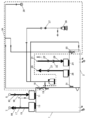
すなわち、この送風機7、8を駆動すると、図3に示すバルブ9、滅菌物質低減化手段10、送風機8、塵埃フィルタ11を介して、本体ケース外の外部空気を作業室1の上方前側から作業室1内に導入することができる。
また、このような外部空気を作業室1に導入しながら、作業室1の排気側の開口(図示せず)から、作業室1内の気体を、塵埃フィルタ13、滅菌物質低減化手段14、バルブ15を介して、本体ケース外に排出することができる。
つまり、バルブ9、滅菌物質低減化手段10、送風機8、塵埃フィルタ11が、作業室1内に外部空気を導入する外気導入路16となっており、バルブ9は本体ケースの上方からの外気を導入するようにしている。
また、塵埃フィルタ13、滅菌物質低減化手段14、バルブ15が、作業室1内の気体を、この作業室1外に排出する気体排気経路17となっており、排気は本体ケースの上方背面側に排出するようにしている。
本実施形態においては、図2に示すように、作業室1内の上方に、この作業室1内に滅菌物質として、過酸化水素水を供給するノズル18(滅菌物質供給手段の一部の一例)を配置している。滅菌物質供給手段34は、ノズル18,20、ノズル18、20に接続されたエアコンプレッサ35、過酸化水素水のボトル36及びポンプ37を含んで構成される。滅菌物質供給手段34は、このノズル18により、過酸化水素水をミスト化して作業室1内に噴出する。
また、作業室1内の上方で、ノズル18からの滅菌物質が直接噴射されない位置に、拡散ファン19が配置されている。
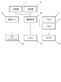
そして、この拡散ファン19、送風機8、バルブ9、15、ノズル18(ノズルバルブを含む)は、図4に示すように、制御手段32に接続している。
さらに、本実施形態においては、図3からも理解されるように、作業準備ボックス2にも、作業室1と同様に、作業準備ボックス2の上方に、送風機23が配置されており、この送風機を駆動することで、作業準備ボックス2内に外部空気を導入したり、滅菌作業後の滅菌物質低減化作業を行わせたりする。
すなわち、この送風機を駆動すると、図3に示すバルブ21、滅菌物質低減化手段22、送風機23、塵埃フィルタ24を介して、作業準備ボックス2の上方から本体ケース外の外部空気を、この作業準備ボックス2に導入することができる。
また、このような外部空気を作業準備ボックス2に導入すると、図2に示す作業準備ボックス2の背面側の開口部25から、作業準備ボックス2内の気体を、図3に示す塵埃フィルタ26、滅菌物質低減化手段27、バルブ28を介して、本体ケース外に排出することができる。
つまり、バルブ21、滅菌物質低減化手段22、送風機23、塵埃フィルタ24が、作業準備ボックス2内に外部空気を導入する外気導入路29となっており、バルブ21は本体ケースの上方からの外気を導入するようにしている。
また、塵埃フィルタ26、滅菌物質低減化手段27、バルブ28が、作業準備ボックス2内の気体を、この作業準備ボックス2外に排出する気体排気経路30となっており、排気は本体ケースの背面側に排出するようにしている。
本実施形態においては、作業準備ボックス2内の上方に、この作業準備ボックス2内に滅菌物質(例えば過酸化水素水)を供給する図3のノズル20(滅菌物質供給手段の一部の一例)を配置している。滅菌物質供給手段34は、このノズル20により、過酸化水素水をミスト化して作業準備ボックス2内に噴出する。
また、作業準備ボックス2内の上方で、ノズル20からの滅菌物質が直接噴射されない位置に、拡散ファン31が配置されている。
また、この拡散ファン31、送風機23、バルブ21、28、ノズル20(ノズルバルブを含む)も、図4と同様に、別の制御手段(図示せず)に接続している。
以上の構成において、作業室1と作業準備ボックス2の滅菌作業、および滅菌物質低減化作業はほぼ同様になっているので、滅菌作業、および滅菌物質低減化作業について、作業室1を例に説明する。
先ず、この滅菌作業は、図1に示したように、作業室1前面の蓋33を閉めた状態で、ノズル18を制御手段32で複数回動作させ、作業室1内に滅菌物質を噴射する。
このとき、拡散ファン19も制御手段32で連続的に動作させており、これにより作業室1内では滅菌物質が広く拡散し、滅菌作業が行われる。例えば、30分後、滅菌物質低減化作業に移る。
このときには、制御手段32でバルブ9、15を開放するとともに、送風機8、9を駆動する(勿論、ノズル18は停止)。
すると、図3に示すバルブ9、滅菌物質低減化手段10、送風機8、塵埃フィルタ11を介して、作業室1の上方から本体ケース外の外部空気を、この作業室1に導入することができる。
また、このような外部空気を作業室1に導入する同時に、図2に示す作業室1の気体排気経路17から、作業室1内の気体を、塵埃フィルタ13、滅菌物質低減化手段14、バルブ15を介して、本体ケース外に排出することができる。
つまり、作業室1内における滅菌物質低減化作業が実行されるのである。
本実施形態で特徴的なのは、この滅菌物質低減化作業時において、制御手段32により、前記ノズル18による滅菌物質の作業室1内への供給後、所定時間(例えば10分間)は、送風機8を3秒ごとに断続運転するとともに、拡散ファン19は連続運転させる構成とした。
このため、送風機8の運転時に、作業室1内に存在するもの、例えばノズル18や拡散ファン19やその他の器具の風下で発生する「気流の滞留状態」は、この送風機8の運転休止状態(慣性だけで回転している状態を含む)には緩和され、また、このときには、拡散ファン19が発生させる気流が前記「気流の滞留状態」部分に作用し、その結果として、前記「気流の滞留状態」部分に残留する滅菌物質を、短時間で効果的に排出することができるようになる。
そして、この10分が経過した後には、送風機8は連続運転を20分行うこととした。
なお、以上の説明は作業室1において説明したが、作業準備ボックス2においても、同様に、制御手段により、前記ノズル20による滅菌物質の作業準備ボックス2内への供給後、所定時間(例えば10分間)は、送風機23を3秒ごとに断続運転するとともに、拡散ファン31は連続運転させる。
以上のごとく本開示は、前記作業室内の気体を拡散させる拡散ファンを設けるとともに、この拡散ファンは制御手段に接続し、この制御手段は、前記滅菌物質供給手段による滅菌物質の作業室内への供給後、所定時間は、送風機を断続運転するとともに、拡散ファンは連続運転させる構成とした。
このため、送風機の運転時に、作業室内に存在するものの風下で発生する「気流の滞留状態」は、この送風機の運転休止状態(慣性だけで回転している状態を含む)には緩和され、また、このときには、拡散ファンによる拡散流が前記「気流の滞留状態」部分に作用し、その結果として、前記「気流の滞留状態」部分に残留する滅菌物質を、短時間で効果的に排出することができるようになる。
したがって、医薬品の開発作業や細胞培養作業などに活用されるアイソレータとしての活用が期待されるものとなる。
1 作業室
2 作業準備ボックス
3 保管ボックス
4 前面開口
5 蓋
7 送風機
8 送風機
9 バルブ
10 滅菌物質低減化手段
11 塵埃フィルタ
13 塵埃フィルタ
14 滅菌物質低減化手段
15 バルブ
16 外気導入路
17 気体排気経路
18 ノズル
19 拡散ファン
20 ノズル
21 バルブ
22 滅菌物質低減化手段
23 送風機
24 塵埃フィルタ
25 開口部
26 塵埃フィルタ
27 滅菌物質低減化手段
28 バルブ
29 外気導入路
30 気体排気経路
31 拡散ファン
32 制御手段
33 蓋
34 滅菌物質供給手段
35 エアコンプレッサ
36 ボトル
37 ポンプ
2 作業準備ボックス
3 保管ボックス
4 前面開口
5 蓋
7 送風機
8 送風機
9 バルブ
10 滅菌物質低減化手段
11 塵埃フィルタ
13 塵埃フィルタ
14 滅菌物質低減化手段
15 バルブ
16 外気導入路
17 気体排気経路
18 ノズル
19 拡散ファン
20 ノズル
21 バルブ
22 滅菌物質低減化手段
23 送風機
24 塵埃フィルタ
25 開口部
26 塵埃フィルタ
27 滅菌物質低減化手段
28 バルブ
29 外気導入路
30 気体排気経路
31 拡散ファン
32 制御手段
33 蓋
34 滅菌物質供給手段
35 エアコンプレッサ
36 ボトル
37 ポンプ
Claims (5)
- 本体ケースと、前記本体ケース内に設けた作業室と、前記作業室内に外部空気を導入する外気導入路と、前記作業室内の気体を前記作業室外に排出する気体排気経路と、前記外気導入路または前記気体排気経路に設けた送風機と、前記作業室内に滅菌物質を供給する滅菌物質供給手段と、前記外気導入路、または前記気体排気経路のうち、少なくとも気体排気経路に設けた滅菌物質低減化手段と、前記送風機、および前記滅菌物質供給手段を接続した制御手段とを備え、前記作業室内の気体を拡散させる拡散ファンを設けるとともに、前記拡散ファンは前記制御手段に接続し、前記制御手段は、前記滅菌物質供給手段による滅菌物質の前記作業室内への供給後、所定時間は、前記送風機を断続運転するとともに、前記拡散ファンは連続運転させる構成としたアイソレータ。
- 前記滅菌物質供給手段は、液体状の滅菌物質を前記作業室内に噴霧するノズルを含む請求項1に記載のアイソレータ。
- 前記ノズルと前記拡散ファンは、前記作業室内に設けた請求項2に記載のアイソレータ。
- 前記制御手段は、所定時間、前記送風機を断続運転するとともに、前記拡散ファンを継続運転させ、この所定時間が経過した後には、前記送風機と前記拡散ファンを連続運転させる構成とした請求項1から3のいずれか一つに記載のアイソレータ。
- 前記外気導入路を前記作業室の上面に連結するとともに、前記作業室内の上方に、前記滅菌物質供給手段と前記拡散ファンを配置した請求項1から4のいずれか一つに記載のアイソレータ。
Applications Claiming Priority (2)
| Application Number | Priority Date | Filing Date | Title |
|---|---|---|---|
| JP2013-163888 | 2013-08-07 | ||
| JP2013163888 | 2013-08-07 |
Publications (1)
| Publication Number | Publication Date |
|---|---|
| WO2015019595A1 true WO2015019595A1 (ja) | 2015-02-12 |
Family
ID=52460951
Family Applications (1)
| Application Number | Title | Priority Date | Filing Date |
|---|---|---|---|
| PCT/JP2014/004067 Ceased WO2015019595A1 (ja) | 2013-08-07 | 2014-08-04 | アイソレータ |
Country Status (1)
| Country | Link |
|---|---|
| WO (1) | WO2015019595A1 (ja) |
Cited By (3)
| Publication number | Priority date | Publication date | Assignee | Title |
|---|---|---|---|---|
| CN107920496A (zh) * | 2015-03-31 | 2018-04-17 | 兴盛生物科技股份有限公司 | 自动化细胞培养培殖器 |
| CN109795857A (zh) * | 2019-02-19 | 2019-05-24 | 浙江大学 | 隔离器集菌操作传输系统 |
| US12098358B2 (en) | 2015-03-31 | 2024-09-24 | Thrive Bioscience, Inc. | Automated incubator with robotic transport |
Citations (4)
| Publication number | Priority date | Publication date | Assignee | Title |
|---|---|---|---|---|
| JP2008014523A (ja) * | 2006-07-03 | 2008-01-24 | Daikin Ind Ltd | 空調システム |
| JP2010046226A (ja) * | 2008-08-20 | 2010-03-04 | Sanyo Electric Co Ltd | アイソレータ |
| JP2010051351A (ja) * | 2008-08-26 | 2010-03-11 | Shibuya Kogyo Co Ltd | アイソレータシステム |
| JP2012024385A (ja) * | 2010-07-26 | 2012-02-09 | Ihi Corp | 有毒物質の除染装置及び除染方法 |
-
2014
- 2014-08-04 WO PCT/JP2014/004067 patent/WO2015019595A1/ja not_active Ceased
Patent Citations (4)
| Publication number | Priority date | Publication date | Assignee | Title |
|---|---|---|---|---|
| JP2008014523A (ja) * | 2006-07-03 | 2008-01-24 | Daikin Ind Ltd | 空調システム |
| JP2010046226A (ja) * | 2008-08-20 | 2010-03-04 | Sanyo Electric Co Ltd | アイソレータ |
| JP2010051351A (ja) * | 2008-08-26 | 2010-03-11 | Shibuya Kogyo Co Ltd | アイソレータシステム |
| JP2012024385A (ja) * | 2010-07-26 | 2012-02-09 | Ihi Corp | 有毒物質の除染装置及び除染方法 |
Cited By (8)
| Publication number | Priority date | Publication date | Assignee | Title |
|---|---|---|---|---|
| CN107920496A (zh) * | 2015-03-31 | 2018-04-17 | 兴盛生物科技股份有限公司 | 自动化细胞培养培殖器 |
| EP3307059A4 (en) * | 2015-03-31 | 2019-03-20 | Thrive Bioscience, Inc. | AUTOMATED CELL CULTURE INCUBATOR |
| US11319523B2 (en) | 2015-03-31 | 2022-05-03 | Thrive Bioscience, Inc. | Automated cell culture incubator |
| US11920121B2 (en) | 2015-03-31 | 2024-03-05 | Thrive Bioscience, Inc. | Automated cell culture incubator |
| US12098358B2 (en) | 2015-03-31 | 2024-09-24 | Thrive Bioscience, Inc. | Automated incubator with robotic transport |
| US12180454B2 (en) | 2015-03-31 | 2024-12-31 | Thrive Bioscience, Inc. | Automated cell culture incubator |
| US12359159B2 (en) | 2015-03-31 | 2025-07-15 | Thrive Bioscience, Inc. | Cell culture incubators with integrated cell manipulation systems |
| CN109795857A (zh) * | 2019-02-19 | 2019-05-24 | 浙江大学 | 隔离器集菌操作传输系统 |
Similar Documents
| Publication | Publication Date | Title |
|---|---|---|
| EP2692848B1 (en) | Decontamination solution spray device | |
| JP6028089B2 (ja) | アイソレータシステム | |
| JP4924570B2 (ja) | アイソレータシステム | |
| KR102316664B1 (ko) | 무균 작업 시스템 | |
| KR102413251B1 (ko) | 무균 작업 시스템 및 무균 작업 시스템을 위한 물품-반입 방법 | |
| JP6271224B2 (ja) | インキュベータおよびインキュベータの除染方法 | |
| JP5823727B2 (ja) | アイソレータ | |
| JP4911632B2 (ja) | アイソレータ | |
| JP2017013036A (ja) | 安全キャビネットおよび安全キャビネットの除染方法 | |
| WO2019012696A1 (ja) | 安全キャビネットおよびその滅菌方法 | |
| WO2015019595A1 (ja) | アイソレータ | |
| JP5189433B2 (ja) | アイソレータ | |
| JP2014195713A (ja) | アイソレータ、アイソレータの制御方法 | |
| JP5341428B2 (ja) | アイソレータ | |
| JP2017000988A (ja) | 安全キャビネットおよび安全キャビネットの除染方法 | |
| JP6724549B2 (ja) | アイソレータシステム | |
| JP6531810B2 (ja) | 無菌作業システム | |
| JP6408894B2 (ja) | アイソレータシステム | |
| JP5877178B2 (ja) | アイソレータ | |
| JP2001000514A (ja) | 滅菌装置 | |
| JP5757965B2 (ja) | アイソレータおよびアイソレータの制御方法 | |
| JP2018001051A (ja) | 安全キャビネット | |
| JP2015148422A (ja) | 加湿装置 |
Legal Events
| Date | Code | Title | Description |
|---|---|---|---|
| 121 | Ep: the epo has been informed by wipo that ep was designated in this application |
Ref document number: 14834030 Country of ref document: EP Kind code of ref document: A1 |
|
| NENP | Non-entry into the national phase |
Ref country code: DE |
|
| NENP | Non-entry into the national phase |
Ref country code: JP |
|
| 122 | Ep: pct application non-entry in european phase |
Ref document number: 14834030 Country of ref document: EP Kind code of ref document: A1 |