WO2015016342A1 - 超音波治療装置 - Google Patents
超音波治療装置 Download PDFInfo
- Publication number
- WO2015016342A1 WO2015016342A1 PCT/JP2014/070324 JP2014070324W WO2015016342A1 WO 2015016342 A1 WO2015016342 A1 WO 2015016342A1 JP 2014070324 W JP2014070324 W JP 2014070324W WO 2015016342 A1 WO2015016342 A1 WO 2015016342A1
- Authority
- WO
- WIPO (PCT)
- Prior art keywords
- ultrasonic
- array
- imaging
- subject
- therapeutic
- Prior art date
- Legal status (The legal status is an assumption and is not a legal conclusion. Google has not performed a legal analysis and makes no representation as to the accuracy of the status listed.)
- Ceased
Links
Images


Classifications
-
- A—HUMAN NECESSITIES
- A61—MEDICAL OR VETERINARY SCIENCE; HYGIENE
- A61B—DIAGNOSIS; SURGERY; IDENTIFICATION
- A61B8/00—Diagnosis using ultrasonic, sonic or infrasonic waves
-
- A—HUMAN NECESSITIES
- A61—MEDICAL OR VETERINARY SCIENCE; HYGIENE
- A61N—ELECTROTHERAPY; MAGNETOTHERAPY; RADIATION THERAPY; ULTRASOUND THERAPY
- A61N7/00—Ultrasound therapy
- A61N7/02—Localised ultrasound hyperthermia
-
- A—HUMAN NECESSITIES
- A61—MEDICAL OR VETERINARY SCIENCE; HYGIENE
- A61B—DIAGNOSIS; SURGERY; IDENTIFICATION
- A61B90/00—Instruments, implements or accessories specially adapted for surgery or diagnosis and not covered by any of the groups A61B1/00 - A61B50/00, e.g. for luxation treatment or for protecting wound edges
- A61B90/36—Image-producing devices or illumination devices not otherwise provided for
- A61B90/37—Surgical systems with images on a monitor during operation
- A61B2090/378—Surgical systems with images on a monitor during operation using ultrasound
-
- A—HUMAN NECESSITIES
- A61—MEDICAL OR VETERINARY SCIENCE; HYGIENE
- A61N—ELECTROTHERAPY; MAGNETOTHERAPY; RADIATION THERAPY; ULTRASOUND THERAPY
- A61N7/00—Ultrasound therapy
- A61N2007/0086—Beam steering
- A61N2007/0095—Beam steering by modifying an excitation signal
Definitions
- the present invention relates to an ultrasonic therapy apparatus, and in particular, in a therapy apparatus having a structure in which imaging and therapeutic ultrasonic arrays are stacked, ultrasonic waves with high accuracy and high output that enable efficient therapeutic action are provided. It relates to technology that enables output.
- a diagnostic transducer including a plurality of arranged first vibration elements and emitting therapeutic ultrasonic waves to the subject and a plurality of arranged second vibration elements, the subject being used for diagnosis
- a diagnostic vibrator for emitting ultrasonic waves and receiving the diagnostic ultrasonic waves reflected by the subject, wherein the therapeutic vibrator and the diagnostic vibrator are laminated.
- An ultrasonic probe (see Patent Document 1) is proposed.
- a therapeutic ultrasonic transducer that irradiates a therapeutic target in a subject with a therapeutic ultrasonic wave, and an ultrasonic image for scanning the inside of the subject with an ultrasonic image for obtaining an image in the subject.
- An ultrasonic therapy apparatus (see Patent Document 2) characterized by comprising a control means has also been proposed.
- a piezoelectric transducer that generates therapy ultrasonic waves and a power amplification module that drives the piezoelectric transducer serve as a heat dissipation plate for the power amplification module.
- An integrated ultrasonic therapy transducer assembly (see Patent Document 3) mounted in a housing has also been proposed.
- an imaging array that oscillates diagnostic ultrasound is stacked on a treatment array that oscillates treatment ultrasound, and has a structure that allows these two types of ultrasound arrays to be used simultaneously. is there.
- the doctor who uses the device has an advantageous characteristic that diagnosis and treatment can be performed seamlessly, but there is a drawback that it is difficult to increase the ultrasonic output of the treatment array due to the fear of adversely affecting the joint structure between the two arrays. there were. Therefore, as in the treatment array 1 shown in FIG. 1, a structure in which the second element 4 and the third element 5 that do not stack the imaging array 2 are added around the first element 3 that stacks the imaging array 2, Technology to compensate for the lack of output has been developed.
- the present invention has been made in view of the above-described problems, and in a treatment apparatus having a structure in which imaging and treatment ultrasonic arrays are stacked, the accuracy of enabling an efficient treatment action is high.
- An object of the present invention is to provide a technology capable of outputting high-power ultrasonic waves.
- the present invention employs the following means. That is, the invention according to claim 1 is a single therapeutic ultrasonic array that irradiates a subject with therapeutic ultrasonic waves, and is laminated on a predetermined region on the single therapeutic ultrasonic array, An ultrasonic imaging array that irradiates imaging ultrasonic waves and receives reflected waves of the imaging ultrasonic waves, and is disposed in a non-laminated area where the imaging ultrasonic arrays are not stacked on the therapeutic ultrasonic array. And a structure in which sound speed adjusting members having a predetermined density are stacked so as to cancel the difference in sound path length from each of the non-stacked region and the predetermined region to the subject.
- the effective sound path length is substantially the same at various points in the laminated structure of the therapeutic ultrasonic array and the imaging ultrasonic array, and the phase shift at the focal point on the subject Suppression of the generation, and hence the accuracy of the ultrasonic beam irradiated to the subject is also improved.
- the therapeutic ultrasonic array is composed of a single element rather than a plurality of elements, the surface amplitude is larger than before, and the ultrasonic output can be increased. Therefore, the vibration efficiency at the time of ultrasonic oscillation can be improved.
- a treatment apparatus having a laminated structure of imaging and treatment ultrasonic arrays it is possible to output high-accuracy and high-accuracy ultrasonic waves that enable efficient treatment.
- the invention according to claim 2 is the ultrasonic therapy apparatus according to claim 1, wherein the imaging ultrasonic superimposing member wired on the non-laminated area is used as the sound velocity adjusting member laminated on the non-laminated area.
- a connection cable for the acoustic wave array is also included.
- the invention according to claim 3 is the ultrasonic therapy apparatus according to claim 1 or 2, wherein the therapeutic ultrasonic array comprising a plurality of elements for irradiating the subject with therapeutic ultrasonic waves, An imaging ultrasonic array that is stacked on any one of a plurality of elements and irradiates the subject with imaging ultrasound and receives reflected waves of the imaging ultrasound;
- the phase of the driving voltage applied to the element is different by a predetermined degree between the stacking target element in which the ultrasonic array is stacked and the non-stacking target element in which the imaging ultrasonic array is not stacked. It is characterized by comprising phase adjusting means for canceling the difference in the respective sound path lengths.
- the ultrasonic therapy apparatus of the present invention in a structure in which the therapeutic ultrasonic array is composed of a plurality of elements, even if the ultrasonic output is large, by adjusting the phase of the drive voltage applied to each element, thus, the effective sound path length is made the same, the occurrence of phase shift at the focal point on the subject is suppressed, and the accuracy of the ultrasonic beam applied to the subject is also improved. That is, in a treatment apparatus having a structure in which imaging and treatment ultrasonic arrays are stacked, it is possible to output high-accuracy ultrasonic waves with good accuracy that enable efficient treatment.
- the ultrasonic treatment apparatus of the present invention in the treatment apparatus having a structure in which the ultrasonic arrays for imaging and treatment are stacked, the accuracy is high and the efficient treatment action is possible. It becomes possible to output an output ultrasonic wave.
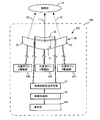
- FIG. 2 is a cross-sectional view illustrating a configuration example of the ultrasonic therapy apparatus 100 according to the first embodiment.
- the ultrasonic therapy apparatus 10 according to the first embodiment is not composed of a plurality of elements as shown in FIG. 2, and therefore is a single therapeutic ultrasonic array 20 and an imaging arranged on the therapeutic ultrasonic array 20.
- the control structure of each of the ultrasonic arrays 20 and 30 are provided.
- the imaging ultrasonic transmission / reception unit 31 and the image processing unit 32 connected to the imaging ultrasonic array 30 are used.
- a display unit 105 for example, the therapeutic array drive unit 25 connected to the therapeutic ultrasonic array 20, the imaging ultrasonic transmission / reception unit 31 and the image processing unit 32 connected to the imaging ultrasonic array 30 are used.
- a display unit 105 for example, the therapeutic array drive unit 25 connected to the therapeutic ultrasonic array 20, the imaging ultrasonic transmission / reception unit 31 and the image processing unit 32 connected to
- the therapeutic array driving unit 25 is a circuit that generates and applies a driving voltage for causing the therapeutic ultrasonic array 20 to oscillate therapeutic ultrasonic waves.
- the imaging ultrasonic transmission / reception unit 31 is a circuit that generates and applies a drive voltage for oscillating imaging ultrasound to the imaging ultrasound array 30 and receives a reflected echo wave returned from the subject 10.
- the image processing unit 32 is a circuit that generates an image based on the above-described reflected echo wave.
- the display unit 105 is a display device that displays an image of the subject 10 generated by the image processing unit 32 from the above-described reflected echo waves.
- the therapeutic array driving unit 25 and the imaging ultrasonic transmission / reception unit 31 have a predetermined set time (e.g., imaging ultrasonic array) in the therapeutic ultrasonic array 20 and the imaging ultrasonic array 30 so that noise is not generated.
- the application control of the drive voltage is performed so that the ultrasonic waves are alternately emitted every 1 second or less and the therapeutic ultrasonic waves are within 10 seconds or less).
- the therapeutic ultrasonic array 20 and imaging ultrasonic array 30 constituting the laminated structure 200 described above, the therapeutic ultrasonic array 20 oscillates about 3 MHz ultrasonic waves, and the imaging ultrasonic array 30 An ultrasonic wave of about 10 MHz having a higher frequency is oscillated.
- the high frequency ultrasonic waves generated by the imaging ultrasonic array 30 have a lower object transmission capability than the low frequency ultrasonic waves generated by the therapeutic ultrasonic array 20. Therefore, the imaging ultrasonic array 30 is stacked on the therapeutic ultrasonic array 20.
- a frequency selective acoustic separation layer 15 is provided between the therapeutic ultrasonic array 20 and the imaging ultrasonic array 30.
- This frequency selective acoustic separation layer 15 is a layer provided by sufficiently increasing the difference in acoustic impedance between the therapeutic ultrasonic array 20 and the imaging ultrasonic array 30 and is not necessary for the therapeutic ultrasonic array 20. While the reflected echo waves reach the therapeutic ultrasonic array 20 and detrimentally affect the output of the therapeutic ultrasonic wave, the therapeutic ultrasonic waves generated by the therapeutic ultrasonic array 20 are the imaging ultrasonic array 30. The function of not impeding the passage of the light toward the subject 10 is shown.
- the therapeutic ultrasonic array 20 and the imaging ultrasonic array 30 are both formed of a concave plate-shaped piezoelectric ceramic that is bent or curved to a predetermined extent.
- the therapeutic ultrasonic array 20 converts the drive voltage applied from the therapeutic array drive unit 25 into mechanical vibration, and deflects and emits therapeutic ultrasonic waves to the subject 10.
- the imaging ultrasonic array 30 converts the drive voltage applied from the imaging ultrasonic transmission / reception unit 31 into mechanical vibration, deflects and transmits imaging ultrasonic waves to the subject 10, and The reflected echo wave generated from 10 is received and converted into an electric signal.
- the path of the therapeutic ultrasound emitted from the therapeutic ultrasound array 20 is the first path 11 from the stacked region 21 where the imaging ultrasound array 30 is stacked on the therapeutic ultrasound array 20 to the subject 10.
- the second path 12 and the third path 13 from the non-stacked region 22 to the subject 10 exist.
- the ultrasonic transmission speed is different between the first path 11 in which the imaging ultrasonic array 30 is included in the path and the second path 12 and the third path in which the imaging ultrasonic array 30 is not included in the path. There is also a difference in the sound path length.
- the sonic speed adjusting member 40 having a predetermined density is provided in the non-stacked region 22 where the imaging ultrasonic array 30 is not stacked in the therapeutic ultrasonic array 20. It has a laminated structure.
- the sonic speed adjusting member 40 has a structure in which, for example, a copper material 42 having a thickness of 50 ⁇ m and a predetermined shape is installed on a polyimide material 41 having a thickness of 250 ⁇ m.
- the level at which the imaging ultrasonic array 30 affects the speed of the therapeutic ultrasonic wave is analyzed or estimated in advance, and this analysis or estimation is performed.
- connection cable 33 (which serves as a path for a reception signal of a drive voltage or a reflected echo wave) of the imaging ultrasonic array 30 wired on the non-laminated area 22 is used. If the material and size are taken into consideration, the above-described sound path length identification becomes even more accurate, suppressing the occurrence of a phase shift of the therapeutic ultrasonic wave at the focal point on the subject 10, and thus irradiating the subject 10 The accuracy of the therapeutic ultrasonic beam to be applied is further improved.
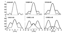
- FIG. 3 shows an example of the beam shape on the focal plane.
- This figure shows the beam shape obtained as a result of calculation when the frequency is 3 MHz, the radius of curvature (focal length) is 30 mm, the aperture width is 15 mm, and the aperture width of the imaging device on the treatment element is 5 mm short axis and 15 mm long axis. is there.
- the phase difference is 0 degree (invention), 45 degrees, 60 degrees, 90 degrees, 135 degrees, and 180 degrees, respectively, on the path that directly reaches the focal point from the treatment element and the path that passes through the imaging element.
- the beam shape on the focal plane is plotted for.
- the horizontal axis of each figure indicates the distance (mm) in the azimuth direction from the focal point of the beam
- the vertical axis indicates the intensity of the beam (no unit).
- a solid line is a plot along a direction parallel to the short axis of the image sensor
- a broken line is a plot along a direction parallel to the long axis of the image sensor.
- the effect of the present invention that makes the effective sound path length constant can also be confirmed from the calculation results of the figure.
- the therapeutic ultrasonic array 20 is composed of a single element rather than a plurality of elements, the surface amplitude at the time of therapeutic ultrasonic oscillation is larger than the conventional (oscillated by each of the plurality of elements), In addition to increasing the ultrasonic output, the conventional structure for preventing moisture intrusion from the gap between the elements is unnecessary, and the vibration efficiency at the time of ultrasonic oscillation can be improved.
- the ultrasonic output in the conventional ultrasonic therapeutic apparatus in which the therapeutic ultrasonic array 20 is composed of a plurality of elements is 10 W / cm 2 , but the ultrasonic output in the ultrasonic therapeutic apparatus 100 of the first embodiment is 1 kW. / Cm 2 , and high output could be realized without other problems.
- FIG. 4 is a cross-sectional view illustrating a configuration example of the ultrasonic therapy apparatus according to the second embodiment.
- the therapeutic ultrasound array 50 in the ultrasound treatment apparatus 100 is composed of a plurality of elements, that is, a first element 51, a second element 52, and a third element 53.
- the imaging ultrasonic array 30 is stacked on the first element 51.
- the first element 51 is a stack target element in which the imaging ultrasonic array 30 is stacked on the first element 51.
- other elements on which the imaging ultrasonic array 30 is not stacked that is, the second element 52 and the third element 53 are non-stacked elements.
- Each of the first element 51, the second element 52, and the third element 53 constituting the therapeutic ultrasonic array 50 is connected to each of the therapeutic array drive units 25A to 25C and can be driven independently. It can be configured.
- the configuration of the imaging ultrasonic array 30 and its drive control function are the same as those in the first embodiment.
- the shape, material (concave plate-shaped piezoelectric ceramic) and function of the first to third elements 51 to 53 and the imaging ultrasonic array 30 constituting the therapeutic ultrasonic array 50, and the therapeutic ultrasonic waves is the same as in the first embodiment described above.
- the phase of the driving voltage applied to the element is made to differ by a predetermined amount by the phase adjusting means), and the difference in sound path length between the first path 11, the second path 12, and the third path 13 is canceled.
- N 3 to 5
- the thickness and sound speed of each layer are t1, t2,..., TN, c1, c2,.
- a phase difference of ⁇ t ⁇ f may be set.
- the level at which the imaging ultrasonic array 30 affects the speed of the therapeutic ultrasonic wave is analyzed or estimated in advance, and the result of this analysis or estimation is shown (second).
- the setting content of the phase that cancels the value of the speed decrease or speed increase (compared with the speed of the third path), that is, the opposite speed increase or speed decrease, may be selected as appropriate.
- the sound path lengths of the paths 11 to 13 are the same, the generation of a phase shift of the therapeutic ultrasonic wave at the focal point on the subject 10 is suppressed, and the accuracy of the therapeutic ultrasonic beam irradiated to the subject 10 is also good. It will be something.
Landscapes
- Health & Medical Sciences (AREA)
- Life Sciences & Earth Sciences (AREA)
- Public Health (AREA)
- Nuclear Medicine, Radiotherapy & Molecular Imaging (AREA)
- Radiology & Medical Imaging (AREA)
- Biomedical Technology (AREA)
- Animal Behavior & Ethology (AREA)
- General Health & Medical Sciences (AREA)
- Engineering & Computer Science (AREA)
- Veterinary Medicine (AREA)
- Biophysics (AREA)
- Physics & Mathematics (AREA)
- Pathology (AREA)
- Heart & Thoracic Surgery (AREA)
- Medical Informatics (AREA)
- Molecular Biology (AREA)
- Surgery (AREA)
- Surgical Instruments (AREA)
- Ultra Sonic Daignosis Equipment (AREA)
Abstract
超音波治療装置100において、被検体10に対し治療用超音波を照射する単体の治療用超音波アレイ20と、単体の治療用超音波アレイ20上の所定領域21に積層され、被検体10に対し撮像用超音波を照射し当該撮像用超音波の反射波を受信する撮像用超音波アレイ30とを備え、治療用超音波アレイ20上のうち撮像用超音波アレイ30を積層していない非積層領域22に、所定密度を有する音速調整部材40が積層し、非積層領域22及び所定領域21の各領域から被検体10に至るそれぞれの音路長の差異をキャンセルする構造を備える。
Description
本発明は、超音波治療装置に関し、特に、撮像用と治療用の各超音波アレイを積層した構造を備える治療装置において、効率的な治療行為が可能となる精度良好で高出力の超音波を出力可能とする技術に関する。
カテーテル誘導下で患部に超音波を照射し、そのエネルギーと加温効果とによって肺塞栓や脳梗塞等における血栓溶解効果を加速させる技術や、超音波照射に伴う発熱により癌細胞滅却を図る技術など、照射対象の生体にエネルギーを印加し発熱を生じさせる超音波を用いた各種の治療技術が開発されている。
こうした超音波を用いた治療技術として以下のようなものが提案されている。すなわち、配列された複数の第1の振動素子を含み、被検体に治療用超音波を射出する治療用振動子と、配列された複数の第2の振動素子を含み、前記被検体に診断用超音波を射出し、前記被検体で反射された前記診断用超音波を受信する診断用振動子とを備え、前記治療用振動子と前記診断用振動子とが積層されていることを特徴とする超音波プローブ(特許文献1参照)などが提案されている。
こうした超音波を用いた治療技術として以下のようなものが提案されている。すなわち、配列された複数の第1の振動素子を含み、被検体に治療用超音波を射出する治療用振動子と、配列された複数の第2の振動素子を含み、前記被検体に診断用超音波を射出し、前記被検体で反射された前記診断用超音波を受信する診断用振動子とを備え、前記治療用振動子と前記診断用振動子とが積層されていることを特徴とする超音波プローブ(特許文献1参照)などが提案されている。
また、治療用超音波を被検体内の治療対象に照射する治療用超音波振動子と、前記被検体内の画像を得るために画像用超音波で前記被検体内を走査する画像用超音波探触子と、前記画像用超音波探触子を介して前記治療用超音波の反射波を受信する受信手段と、前記受信手段による受信信号に基づいて前記治療用超音波の強度を制御する制御手段とを具備したことを特徴とする超音波治療装置(特許文献2参照)なども提案されている。
また、超音波機器を最小化し、電磁干渉および放熱を大幅に削減すべく、療法超音波を発生させる圧電トランスデューサと、この圧電トランスデューサを駆動する電力増幅モジュールとを、電力増幅モジュールの放熱板となる筐体内に取り付けた集積超音波療法トランスデューサアセンブリ(特許文献3参照)なども提案されている。
また、超音波機器を最小化し、電磁干渉および放熱を大幅に削減すべく、療法超音波を発生させる圧電トランスデューサと、この圧電トランスデューサを駆動する電力増幅モジュールとを、電力増幅モジュールの放熱板となる筐体内に取り付けた集積超音波療法トランスデューサアセンブリ(特許文献3参照)なども提案されている。
従来の治療装置においては、診断用超音波を発振する撮像アレイが、治療用超音波を発振する治療アレイ上に積層され、これら2種の超音波アレイを同時に利用可能とする構造を備えるものがある。その場合、該当装置を使用する医師において診断と治療をシームレスに行えるとの有利な特性を備える一方、両アレイ間の接合構造に悪影響を及ぼす懸念から治療アレイの超音波出力を増大させにくい欠点があった。
そこで、図1に示す治療アレイ1のごとく、撮像アレイ2を積層させた第1素子3の周囲に、撮像アレイ2を積層させない第2素子4および第3素子5を追加した構造を採用し、出力不足を補う技術が開発されている。
ところが、上部に撮像アレイを載置した第1素子3と、撮像アレイを載置していない第2素子4、第3素子5とでは実効的な音路長が異なることとなるため、焦点における位相ずれが発生し、患部等の目標物に照射される超音波ビームが劣化するおそれがある。また、上述した第1~第3の各素子3~5間の間隙から装置内に水分が浸入することを防止すべく、各素子3~5のそれぞれの周囲を筐体等に液密に固定する必要がある。こうした構造は、超音波発振に際しての振動効率を各素子3~5で低下させることにつながり、エネルギー消費の増大や超音波出力の低下等を招く恐れがあるという課題がある。
本発明は、上記のような課題に鑑みなされたものであって、撮像用と治療用の各超音波アレイを積層した構造を備える治療装置において、効率的な治療行為が可能となる精度良好で高出力の超音波を出力可能とする技術を提供することを目的とする。
そこで、図1に示す治療アレイ1のごとく、撮像アレイ2を積層させた第1素子3の周囲に、撮像アレイ2を積層させない第2素子4および第3素子5を追加した構造を採用し、出力不足を補う技術が開発されている。
ところが、上部に撮像アレイを載置した第1素子3と、撮像アレイを載置していない第2素子4、第3素子5とでは実効的な音路長が異なることとなるため、焦点における位相ずれが発生し、患部等の目標物に照射される超音波ビームが劣化するおそれがある。また、上述した第1~第3の各素子3~5間の間隙から装置内に水分が浸入することを防止すべく、各素子3~5のそれぞれの周囲を筐体等に液密に固定する必要がある。こうした構造は、超音波発振に際しての振動効率を各素子3~5で低下させることにつながり、エネルギー消費の増大や超音波出力の低下等を招く恐れがあるという課題がある。
本発明は、上記のような課題に鑑みなされたものであって、撮像用と治療用の各超音波アレイを積層した構造を備える治療装置において、効率的な治療行為が可能となる精度良好で高出力の超音波を出力可能とする技術を提供することを目的とする。
上記のような課題を解決するために、本発明は、以下のような手段を採用している。
すなわち、請求項1に係る発明は、被検体に対し治療用超音波を照射する単体の治療用超音波アレイと、前記単体の治療用超音波アレイ上の所定領域に積層され、前記被検体に対し撮像用超音波を照射し当該撮像用超音波の反射波を受信する撮像用超音波アレイとを備え、治療用超音波アレイ上のうち撮像用超音波アレイを積層していない非積層領域に、所定密度を有する音速調整部材を積層し、前記非積層領域及び前記所定領域の各領域から前記被検体に至るそれぞれの音路長の差異をキャンセルする構造を備えることを特徴とする。
本発明の超音波治療装置によれば、治療用超音波アレイと撮像用超音波アレイとの積層構造における各所で実効的な音路長を実質的に同一とし、被検体上の焦点における位相ずれ発生の抑制、ひいては被検体に照射される超音波ビームの精度も良好なものとなる。また、治療用超音波アレイが複数素子ではなく単体の素子からなっているため、表面振幅が従来より大きくなり、超音波出力を増大できる上、従来のように各素子間の間隙からの水分浸入を防止するための構造が不要であるので、超音波発振に際しての振動効率を良好なものとできる。
つまり、撮像と治療の各超音波アレイの積層構造を備える治療装置において、効率的な治療行為が可能となる精度良好で高出力の超音波を出力することができる。
すなわち、請求項1に係る発明は、被検体に対し治療用超音波を照射する単体の治療用超音波アレイと、前記単体の治療用超音波アレイ上の所定領域に積層され、前記被検体に対し撮像用超音波を照射し当該撮像用超音波の反射波を受信する撮像用超音波アレイとを備え、治療用超音波アレイ上のうち撮像用超音波アレイを積層していない非積層領域に、所定密度を有する音速調整部材を積層し、前記非積層領域及び前記所定領域の各領域から前記被検体に至るそれぞれの音路長の差異をキャンセルする構造を備えることを特徴とする。
本発明の超音波治療装置によれば、治療用超音波アレイと撮像用超音波アレイとの積層構造における各所で実効的な音路長を実質的に同一とし、被検体上の焦点における位相ずれ発生の抑制、ひいては被検体に照射される超音波ビームの精度も良好なものとなる。また、治療用超音波アレイが複数素子ではなく単体の素子からなっているため、表面振幅が従来より大きくなり、超音波出力を増大できる上、従来のように各素子間の間隙からの水分浸入を防止するための構造が不要であるので、超音波発振に際しての振動効率を良好なものとできる。
つまり、撮像と治療の各超音波アレイの積層構造を備える治療装置において、効率的な治療行為が可能となる精度良好で高出力の超音波を出力することができる。
また、請求項2に係る発明は、請求項1に記載の超音波治療装置であって、前記非積層領域に積層した前記音速調整部材として、前記非積層領域上に配線された前記撮像用超音波アレイの接続ケーブルも含むことを特徴とする。
本発明の超音波治療装置によれば、前記非積層領域及び前記所定領域の各領域から前記被検体に至るそれぞれの音路長の差異をより高い精度でキャンセルすることにつながり、実効的な音路長の同一化も更に精度良く図られることとなる。
さらに、請求項3に係る発明は、請求項1または2に記載の超音波治療装置であって、被検体に対し治療用超音波を照射する複数の素子からなる治療用超音波アレイと、前記複数の素子のうちいずれかの素子上に積層され、前記被検体に対し撮像用超音波を照射し当該撮像用超音波の反射波を受信する撮像用超音波アレイとを備え、上部に撮像用超音波アレイを積層した積層対象素子と、撮像用超音波アレイを積層していない非積層対象素子とで、素子に印加する駆動電圧の位相を所定程度相違させ、前記各素子から前記被検体に至るそれぞれの音路長の差異をキャンセルする、位相調整手段を備えることを特徴とする。
本発明の超音波治療装置によれば、前記非積層領域及び前記所定領域の各領域から前記被検体に至るそれぞれの音路長の差異をより高い精度でキャンセルすることにつながり、実効的な音路長の同一化も更に精度良く図られることとなる。
さらに、請求項3に係る発明は、請求項1または2に記載の超音波治療装置であって、被検体に対し治療用超音波を照射する複数の素子からなる治療用超音波アレイと、前記複数の素子のうちいずれかの素子上に積層され、前記被検体に対し撮像用超音波を照射し当該撮像用超音波の反射波を受信する撮像用超音波アレイとを備え、上部に撮像用超音波アレイを積層した積層対象素子と、撮像用超音波アレイを積層していない非積層対象素子とで、素子に印加する駆動電圧の位相を所定程度相違させ、前記各素子から前記被検体に至るそれぞれの音路長の差異をキャンセルする、位相調整手段を備えることを特徴とする。
本発明の超音波治療装置によれば、治療用超音波アレイが複数の素子からなる構造において、超音波出力を大きなものとしても、各素子に印加する駆動電圧の位相を調整することにより、各所で実効的な音路長を同一とし、被検体上の焦点における位相ずれ発生の抑制、ひいては被検体に照射される超音波ビームの精度も良好なものとなる。つまり、撮像用と治療用の各超音波アレイを積層する構造を備える治療装置において、効率的な治療行為が可能となる精度良好で高出力の超音波を出力することができる。
以上説明したように、本発明の超音波治療装置によれば、撮像用と治療用の各超音波アレイを積層する構造を備える治療装置において、効率的な治療行為が可能となる精度良好で高出力の超音波を出力することが可能となる。
---第1の形態---
以下、図面を参照しながら本発明の実施の形態について説明する。図2は、第1実施形態の超音波治療装置100の構成例を示す断面図である。第1実施形態における超音波治療装置10は、図2にて示すような、複数素子から構成されず、従って単体である治療用超音波アレイ20と、治療用超音波アレイ20上に配置した撮像用超音波アレイ30との積層構造200と、こうした各超音波アレイ20、30の制御機能とを備えている。ここで、制御機能としては、例えば、治療用超音波アレイ20に接続された治療用アレイ駆動部25と、撮像用超音波アレイ30に接続された撮像用超音波送受部31および画像処理部32と、表示部105とが含まれる。
このうち、治療用アレイ駆動部25は、治療用超音波アレイ20に治療用超音波を発振させる駆動電圧を生成、印加する回路である。また、撮像用超音波送受部31は、撮像用超音波アレイ30に撮像用超音波を発振させる駆動電圧を生成、印加する一方、被検体10から返される反射エコー波を受信する回路である。また、画像処理部32は、前述の反射エコー波に基づき画像生成を行う回路である。また、表示部105は、上述した反射エコー波から画像処理部が32が生成した被検体10の画像を表示するディスプレイ装置である。なお、治療用アレイ駆動部25と撮像用超音波送受部31は、ノイズが発生しないように、治療用超音波アレイ20と撮像用超音波アレイ30とにおいて所定の設定時間(例:撮像用超音波は1秒以内程度、治療用超音波は10秒以内程度)ごとに交互に超音波を射出するよう、駆動電圧の印加制御を行うものとなる。
以下、図面を参照しながら本発明の実施の形態について説明する。図2は、第1実施形態の超音波治療装置100の構成例を示す断面図である。第1実施形態における超音波治療装置10は、図2にて示すような、複数素子から構成されず、従って単体である治療用超音波アレイ20と、治療用超音波アレイ20上に配置した撮像用超音波アレイ30との積層構造200と、こうした各超音波アレイ20、30の制御機能とを備えている。ここで、制御機能としては、例えば、治療用超音波アレイ20に接続された治療用アレイ駆動部25と、撮像用超音波アレイ30に接続された撮像用超音波送受部31および画像処理部32と、表示部105とが含まれる。
このうち、治療用アレイ駆動部25は、治療用超音波アレイ20に治療用超音波を発振させる駆動電圧を生成、印加する回路である。また、撮像用超音波送受部31は、撮像用超音波アレイ30に撮像用超音波を発振させる駆動電圧を生成、印加する一方、被検体10から返される反射エコー波を受信する回路である。また、画像処理部32は、前述の反射エコー波に基づき画像生成を行う回路である。また、表示部105は、上述した反射エコー波から画像処理部が32が生成した被検体10の画像を表示するディスプレイ装置である。なお、治療用アレイ駆動部25と撮像用超音波送受部31は、ノイズが発生しないように、治療用超音波アレイ20と撮像用超音波アレイ30とにおいて所定の設定時間(例:撮像用超音波は1秒以内程度、治療用超音波は10秒以内程度)ごとに交互に超音波を射出するよう、駆動電圧の印加制御を行うものとなる。
また、上述の積層構造200を構成する治療用超音波アレイ20および撮像用超音波アレイ30のうち、治療用超音波アレイ20は約3MHzの超音波を発振し、撮像用超音波アレイ30はそれよりも高い周波数の、約10MHzの超音波を発振する。撮像用超音波アレイ30が生じる高い周波数の超音波は、治療用超音波アレイ20が生じる低い周波数の超音波よりも物体透過能力が低い。そのため、治療用超音波アレイ20上に撮像用超音波アレイ30を積層した構造となっている。
また、治療用超音波アレイ20と撮像用超音波アレイ30との間には、周波数選択性音響分離層15が設けられている。この周波数選択性音響分離層15は、治療用超音波アレイ20と撮像用超音波アレイ30とで音響インピーダンスの差異を十分大きくすることで設けられる層であり、治療用超音波アレイ20にとっては不要な反射エコー波が治療用超音波アレイ20にまで到達して治療用超音波の出力に悪影響を与えることを抑止する一方、治療用超音波アレイ20による治療用超音波は撮像用超音波アレイ30を透過して被検体10に向けて進むことを阻害しない機能を発揮する。
また、治療用超音波アレイ20と撮像用超音波アレイ30との間には、周波数選択性音響分離層15が設けられている。この周波数選択性音響分離層15は、治療用超音波アレイ20と撮像用超音波アレイ30とで音響インピーダンスの差異を十分大きくすることで設けられる層であり、治療用超音波アレイ20にとっては不要な反射エコー波が治療用超音波アレイ20にまで到達して治療用超音波の出力に悪影響を与えることを抑止する一方、治療用超音波アレイ20による治療用超音波は撮像用超音波アレイ30を透過して被検体10に向けて進むことを阻害しない機能を発揮する。
なお、治療用超音波アレイ20および撮像用超音波アレイ30は、いずれも所定程度屈曲ないし湾曲した凹板状の圧電セラミックスで形成されている。治療用超音波アレイ20は、治療用アレイ駆動部25から印加された駆動電圧を機械的振動に変換し、被検体10に治療用の超音波を偏向射出する。また、撮像用超音波アレイ30は、撮像用超音波送受部31から印加された駆動電圧を機械的振動に変換し、被検体10に対して撮像用超音波を偏向送波すると共に、被検体10から発生する反射エコー波を受信して電気信号に変換する。
治療用超音波アレイ20から射出された治療用超音波の経路は、治療用超音波アレイ20上で撮像用超音波アレイ30が積層された積層領域21から被検体10に至る第1経路11と、非積層領域22から被検体10に至る第2経路12、第3経路13とが存在する。撮像用超音波アレイ30が経路中に含まれる第1経路11と、撮像用超音波アレイ30が経路中に含まれない第2経路12および第3経路とでは超音波の伝達速度が異なり、ひいては音路長にも差異が生じる。
治療用超音波アレイ20から射出された治療用超音波の経路は、治療用超音波アレイ20上で撮像用超音波アレイ30が積層された積層領域21から被検体10に至る第1経路11と、非積層領域22から被検体10に至る第2経路12、第3経路13とが存在する。撮像用超音波アレイ30が経路中に含まれる第1経路11と、撮像用超音波アレイ30が経路中に含まれない第2経路12および第3経路とでは超音波の伝達速度が異なり、ひいては音路長にも差異が生じる。
そこで第1実施形態の超音波治療装置100においては、治療用超音波アレイ20上のうち撮像用超音波アレイ30を積層していない非積層領域22には、所定密度を有する音速調整部材40が積層された構造を備えている。この音速調整部材40は、例えば厚さ250μmのポリイミド材41上に、厚さ50μmで所定形状の銅材42を設置した構造となっている。勿論、こうした音速調整部材40の構造や使用部材の選定に際しては、撮像用超音波アレイ30が治療用超音波の速度に影響を与えるレベルを事前に解析ないし推定しておき、この解析ないし推定の結果が示す(第2、第3経路の速度と比較した)速度低下ないし速度上昇の値をキャンセルする、すなわち反対の速度上昇ないし速度低下を図れるものを適宜選択すればよい。こうした速度調整部材40を採用して各経路11~13における超音波速度の統一を図ることで、各経路11~13の音路長に差異が生じることを抑止できる。
各経路11~13の音路長を同一とすれば、被検体10上の焦点における治療用超音波の位相ずれ発生の抑制、ひいては被検体10に照射される治療用超音波ビームの精度も良好なものとなる。なお、非積層領域22に積層した速度調整部材40として、非積層領域22上に配線された撮像用超音波アレイ30の接続ケーブル33(駆動電圧や反射エコー波の受信信号の経路となる)の材質、サイズも含めて考慮すれば、上述した音路長の同一化が更に高精度なものとなり、被検体10上の焦点における治療用超音波の位相ずれ発生の抑制、ひいては被検体10に照射される治療用超音波ビームの精度も更に良好なものとなる。
各経路11~13の音路長を同一とすれば、被検体10上の焦点における治療用超音波の位相ずれ発生の抑制、ひいては被検体10に照射される治療用超音波ビームの精度も良好なものとなる。なお、非積層領域22に積層した速度調整部材40として、非積層領域22上に配線された撮像用超音波アレイ30の接続ケーブル33(駆動電圧や反射エコー波の受信信号の経路となる)の材質、サイズも含めて考慮すれば、上述した音路長の同一化が更に高精度なものとなり、被検体10上の焦点における治療用超音波の位相ずれ発生の抑制、ひいては被検体10に照射される治療用超音波ビームの精度も更に良好なものとなる。
図3に焦点面上でのビーム形状の例を示す。同図は、周波数3MHz、曲率半径(焦点距離)30mm、口径幅15mm、治療素子上の撮像素子の口径幅を短軸5mm、長軸15mmとしたときに計算の結果、得られたビーム形状である。同図では、治療素子から直接焦点に到達した経路と、撮像素子を通った経路のそれぞれに位相差を0度(本発明)、45度、60度、90度、135度、180度のそれぞれの場合について焦点面上でのビーム形状をプロットしてある。ここで、各図の横軸はビームの焦点からの方位方向への距離(mm)、縦軸はビームの強度(単位なし)を示している 。実線は撮像素子の短軸に平行な方向、破線は撮像素子の長軸に平行な方向に沿ったプロットである。ビーム強度は位相差0度のときの最大値で規格化してある。この結果から、位相差によっては最大音圧が70%程度に低下し(エネルギーは音圧の二乗に比例するので、このときのエネルギーは半分となる)、ピークの位置が2mm弱ずれていることが確認できる。このように実効的な音路長を一定とする本発明の効果が図の計算結果からも確認できる。
第1実施形態においては、治療用超音波アレイ20が複数素子ではなく単体の素子からなっているため、治療用超音波発振時の表面振幅が従来(複数素子のそれぞれで発振)より大きくなり、超音波出力を増大できる上、従来のように各素子間の間隙からの水分浸入を防止するための構造は不要で、超音波発振に際しての振動効率を良好なものとできる。ここで、口径の中心で最大音圧、端で0になる音圧分布をハニング関数 (0.5-0.5cos(2px);0<x<1)に近似すると、本発明による場合と比べて、従来技術のように素子が三つに分かれている場合は、素子表面の音圧の積分値が51%に低下、すなわちエネルギーに換算すると26%にまで低下してしまう(ここでは、三つの素子に分割された場合の音圧分布を、3つ並んだハニング関数と、全体を覆う一つのハニング関数の積から概算した。)。治療用超音波アレイ20を複数素子で構成した従来の超音波治療装置における超音波出力は、10W/cm2であったが、第1実施形態の超音波治療装置100における超音波出力は、1kW/cm2となり、他の不具合無く高出力を実現できた。
第1実施形態においては、治療用超音波アレイ20が複数素子ではなく単体の素子からなっているため、治療用超音波発振時の表面振幅が従来(複数素子のそれぞれで発振)より大きくなり、超音波出力を増大できる上、従来のように各素子間の間隙からの水分浸入を防止するための構造は不要で、超音波発振に際しての振動効率を良好なものとできる。ここで、口径の中心で最大音圧、端で0になる音圧分布をハニング関数 (0.5-0.5cos(2px);0<x<1)に近似すると、本発明による場合と比べて、従来技術のように素子が三つに分かれている場合は、素子表面の音圧の積分値が51%に低下、すなわちエネルギーに換算すると26%にまで低下してしまう(ここでは、三つの素子に分割された場合の音圧分布を、3つ並んだハニング関数と、全体を覆う一つのハニング関数の積から概算した。)。治療用超音波アレイ20を複数素子で構成した従来の超音波治療装置における超音波出力は、10W/cm2であったが、第1実施形態の超音波治療装置100における超音波出力は、1kW/cm2となり、他の不具合無く高出力を実現できた。
---第2の形態---
図4は第2実施形態の超音波治療装置の構成例を示す断面図である。続いて、治療用超音波アレイが複数の素子からなる従来の構造において、被検体10上の焦点における位相ずれ発生の抑制、ひいては被検体10に照射される超音波ビームの精度を良好なものとする技術について説明する。
この場合、超音波治療装置100における治療用超音波アレイ50は、複数の素子、すなわち第1素子51、第2素子52、第3素子53から構成されている。また、第1~第3の各素子51~53のうち、例えば第1素子51上には撮像用超音波アレイ30が積層された構造となっている。この第1素子51を、その上部に撮像用超音波アレイ30を積層した積層対象素子とする。他方、撮像用超音波アレイ30を積層していないその他の素子すなわち第2素子52、第3素子53は非積層対象素子とする。
なお、治療用超音波アレイ50を構成する第1素子51、第2素子52、第3素子53のそれぞれは、各治療用アレイ駆動部25A~25Cに接続されており、独立に駆動することができる構成となっている。一方、撮像用超音波アレイ30の構成とその駆動制御の機能等については上述した第1実施形態と同様である。また、治療用超音波アレイ50を構成する第1~第3の各素子51~53と撮像用超音波アレイ30の形状、材質(凹板状の圧電セラミックス)や機能、および、治療用超音波アレイ20と撮像用超音波アレイ30との間に設ける周波数選択性音響分離層15の存在等も上述した第1実施形態と同様である。
図4は第2実施形態の超音波治療装置の構成例を示す断面図である。続いて、治療用超音波アレイが複数の素子からなる従来の構造において、被検体10上の焦点における位相ずれ発生の抑制、ひいては被検体10に照射される超音波ビームの精度を良好なものとする技術について説明する。
この場合、超音波治療装置100における治療用超音波アレイ50は、複数の素子、すなわち第1素子51、第2素子52、第3素子53から構成されている。また、第1~第3の各素子51~53のうち、例えば第1素子51上には撮像用超音波アレイ30が積層された構造となっている。この第1素子51を、その上部に撮像用超音波アレイ30を積層した積層対象素子とする。他方、撮像用超音波アレイ30を積層していないその他の素子すなわち第2素子52、第3素子53は非積層対象素子とする。
なお、治療用超音波アレイ50を構成する第1素子51、第2素子52、第3素子53のそれぞれは、各治療用アレイ駆動部25A~25Cに接続されており、独立に駆動することができる構成となっている。一方、撮像用超音波アレイ30の構成とその駆動制御の機能等については上述した第1実施形態と同様である。また、治療用超音波アレイ50を構成する第1~第3の各素子51~53と撮像用超音波アレイ30の形状、材質(凹板状の圧電セラミックス)や機能、および、治療用超音波アレイ20と撮像用超音波アレイ30との間に設ける周波数選択性音響分離層15の存在等も上述した第1実施形態と同様である。
第2実施形態の超音波治療装置100において、積層対象素子たる第1素子51から被検体10に至る第1経路11と、非積層対象素子たる第2素子52から被検体10に至る第2経路12、および非積層対象素子たる第3素子53から被検体10に至る第3経路13とでは、超音波の伝達速度が異なり、ひいては音路長にも差異が生じてしまう。
そこで第2実施形態の超音波治療装置100においては、上述した積層対象素子たる第1素子51と、非積層対象素子たる第2素子53および第3素子53とで、治療用アレイ駆動部25(位相調整手段)により素子に印加する駆動電圧の位相を所定程度相違させ、第1経路11と、第2経路12および第3経路13との間での、音路長の差異をキャンセルする。
具体的には、撮像アレイを構成する材料がN種類の場合(N=3~5)に、各層の厚みと音速をそれぞれt1、t2、・・・、tN、c1、c2、・・・cN、水の音速をcWとすると、積層された素子での音路長と、積層されない素子の音路長それぞれの伝搬時間の差Δtは次式のようになるので、
Δt=(t1/c1+t2/c2+・・・+tN/cN)-(t1+t2+・・・+tN)/cW
このΔtをキャンセルするように、周波数がfの場合はΔt×fの位相差を設定すればよい。
そこで第2実施形態の超音波治療装置100においては、上述した積層対象素子たる第1素子51と、非積層対象素子たる第2素子53および第3素子53とで、治療用アレイ駆動部25(位相調整手段)により素子に印加する駆動電圧の位相を所定程度相違させ、第1経路11と、第2経路12および第3経路13との間での、音路長の差異をキャンセルする。
具体的には、撮像アレイを構成する材料がN種類の場合(N=3~5)に、各層の厚みと音速をそれぞれt1、t2、・・・、tN、c1、c2、・・・cN、水の音速をcWとすると、積層された素子での音路長と、積層されない素子の音路長それぞれの伝搬時間の差Δtは次式のようになるので、
Δt=(t1/c1+t2/c2+・・・+tN/cN)-(t1+t2+・・・+tN)/cW
このΔtをキャンセルするように、周波数がfの場合はΔt×fの位相差を設定すればよい。
勿論、こうした駆動電圧の位相設定に際しては、撮像用超音波アレイ30が治療用超音波の速度に影響を与えるレベルを事前に解析ないし推定しておき、この解析ないし推定の結果が示す(第2、第3経路の速度と比較した)速度低下ないし速度上昇の値をキャンセルする、すなわち反対の速度上昇ないし速度低下を図れる位相の設定内容を適宜選択すればよい。こうして各経路11~13における速度の統一を図ることで、各経路11~13の音路長に差異が生じることを抑止できる。
各経路11~13の音路長を同一とすれば、被検体10上の焦点における治療用超音波の位相ずれ発生の抑制、ひいては被検体10に照射される治療用超音波ビームの精度も良好なものとなる。
以上本実施形態によれば、撮像と治療の各超音波アレイの積層構造を備える治療装置において、効率的な治療行為が可能となる精度良好で高出力の超音波を出力することが可能とる。
各経路11~13の音路長を同一とすれば、被検体10上の焦点における治療用超音波の位相ずれ発生の抑制、ひいては被検体10に照射される治療用超音波ビームの精度も良好なものとなる。
以上本実施形態によれば、撮像と治療の各超音波アレイの積層構造を備える治療装置において、効率的な治療行為が可能となる精度良好で高出力の超音波を出力することが可能とる。
10 被検体
11 第1経路
12 第2経路
13 第3経路
15 周波数選択性音響分離層
20 単体の治療用超音波アレイ
21 治療用超音波アレイ上の積層領域(所定領域)
22 治療用超音波アレイ上の非積層領域
25 治療用アレイ駆動部(位相調整手段)
30 撮像用超音波アレイ
31 撮像用超音波送受部
32 画像処理部
33 接続ケーブル
40 音速調整部材
50 治療用超音波アレイ
51 第1素子(積層対象素子)
52 第2素子(非積層対象素子)
53 第3素子(非積層対象素子)
100 超音波治療装置
105 表示部
200 超音波アレイ積層構造
11 第1経路
12 第2経路
13 第3経路
15 周波数選択性音響分離層
20 単体の治療用超音波アレイ
21 治療用超音波アレイ上の積層領域(所定領域)
22 治療用超音波アレイ上の非積層領域
25 治療用アレイ駆動部(位相調整手段)
30 撮像用超音波アレイ
31 撮像用超音波送受部
32 画像処理部
33 接続ケーブル
40 音速調整部材
50 治療用超音波アレイ
51 第1素子(積層対象素子)
52 第2素子(非積層対象素子)
53 第3素子(非積層対象素子)
100 超音波治療装置
105 表示部
200 超音波アレイ積層構造
Claims (3)
- 被検体に対し治療用超音波を照射する単体の治療用超音波アレイと、前記単体の治療用超音波アレイ上の所定領域に積層され、前記被検体に対し撮像用超音波を照射し当該撮像用超音波の反射波を受信する撮像用超音波アレイとを備え、
治療用超音波アレイ上のうち撮像用超音波アレイを積層していない非積層領域に、所定密度を有する音速調整部材を積層し、前記非積層領域及び前記所定領域の各領域から前記被検体に至るそれぞれの音路長の差異をキャンセルする構造を備えることを特徴とする超音波治療装置。 - 前記非積層領域に積層した前記速度調整部材として、前記非積層領域上に配線された前記撮像用超音波アレイの接続ケーブルも含むことを特徴とする請求項1に記載の超音波治療装置。
- 被検体に対し治療用超音波を照射する複数の素子からなる治療用超音波アレイと、前記複数の素子のうちいずれかの素子上に積層され、前記被検体に対し撮像用超音波を照射し当該撮像用超音波の反射波を受信する撮像用超音波アレイとを備え、
上部に撮像用超音波アレイを積層した積層対象素子と、撮像用超音波アレイを積層していない非積層対象素子とで、素子に印加する駆動電圧の位相を所定程度相違させ、前記各素子から前記被検体に至るそれぞれの音路長の差異をキャンセルする、位相調整手段を備えることを特徴とする超音波治療装置。
Applications Claiming Priority (2)
| Application Number | Priority Date | Filing Date | Title |
|---|---|---|---|
| JP2013161064A JP6300397B2 (ja) | 2013-08-02 | 2013-08-02 | 超音波治療装置 |
| JP2013-161064 | 2013-08-02 |
Publications (1)
| Publication Number | Publication Date |
|---|---|
| WO2015016342A1 true WO2015016342A1 (ja) | 2015-02-05 |
Family
ID=52431865
Family Applications (1)
| Application Number | Title | Priority Date | Filing Date |
|---|---|---|---|
| PCT/JP2014/070324 Ceased WO2015016342A1 (ja) | 2013-08-02 | 2014-08-01 | 超音波治療装置 |
Country Status (2)
| Country | Link |
|---|---|
| JP (1) | JP6300397B2 (ja) |
| WO (1) | WO2015016342A1 (ja) |
Cited By (1)
| Publication number | Priority date | Publication date | Assignee | Title |
|---|---|---|---|---|
| CN114948079A (zh) * | 2022-05-06 | 2022-08-30 | 苏州谱洛医疗科技有限公司 | 一种超声换能装置及其治疗系统 |
Families Citing this family (1)
| Publication number | Priority date | Publication date | Assignee | Title |
|---|---|---|---|---|
| KR101935375B1 (ko) | 2016-02-01 | 2019-01-07 | 서강대학교산학협력단 | Hifu와 초음파 영상을 위한 초음파 치료 장치 및 그 제어 방법 |
Citations (6)
| Publication number | Priority date | Publication date | Assignee | Title |
|---|---|---|---|---|
| JPS61206434A (ja) * | 1985-03-12 | 1986-09-12 | 富士通株式会社 | 超音波診断装置 |
| JPH03151952A (ja) * | 1989-11-08 | 1991-06-28 | Matsushita Electric Ind Co Ltd | 超音波治療装置 |
| JPH04273699A (ja) * | 1991-02-28 | 1992-09-29 | Toshiba Corp | 超音波検査装置 |
| JP2004154205A (ja) * | 2002-11-05 | 2004-06-03 | Hitachi Ltd | 超音波装置 |
| JP2005103193A (ja) * | 2003-10-02 | 2005-04-21 | Hitachi Medical Corp | 超音波送波器及びこれを用いた超音波装置 |
| JP2009503990A (ja) * | 2005-07-26 | 2009-01-29 | アー.ヤー. アンゲルセン、ビョルン | 二重周波数帯域の超音波送受波器アレイ |
-
2013
- 2013-08-02 JP JP2013161064A patent/JP6300397B2/ja not_active Expired - Fee Related
-
2014
- 2014-08-01 WO PCT/JP2014/070324 patent/WO2015016342A1/ja not_active Ceased
Patent Citations (6)
| Publication number | Priority date | Publication date | Assignee | Title |
|---|---|---|---|---|
| JPS61206434A (ja) * | 1985-03-12 | 1986-09-12 | 富士通株式会社 | 超音波診断装置 |
| JPH03151952A (ja) * | 1989-11-08 | 1991-06-28 | Matsushita Electric Ind Co Ltd | 超音波治療装置 |
| JPH04273699A (ja) * | 1991-02-28 | 1992-09-29 | Toshiba Corp | 超音波検査装置 |
| JP2004154205A (ja) * | 2002-11-05 | 2004-06-03 | Hitachi Ltd | 超音波装置 |
| JP2005103193A (ja) * | 2003-10-02 | 2005-04-21 | Hitachi Medical Corp | 超音波送波器及びこれを用いた超音波装置 |
| JP2009503990A (ja) * | 2005-07-26 | 2009-01-29 | アー.ヤー. アンゲルセン、ビョルン | 二重周波数帯域の超音波送受波器アレイ |
Cited By (2)
| Publication number | Priority date | Publication date | Assignee | Title |
|---|---|---|---|---|
| CN114948079A (zh) * | 2022-05-06 | 2022-08-30 | 苏州谱洛医疗科技有限公司 | 一种超声换能装置及其治疗系统 |
| CN114948079B (zh) * | 2022-05-06 | 2025-11-04 | 苏州谱洛医疗科技有限公司 | 一种超声换能装置及其治疗系统 |
Also Published As
| Publication number | Publication date |
|---|---|
| JP6300397B2 (ja) | 2018-03-28 |
| JP2015029664A (ja) | 2015-02-16 |
Similar Documents
| Publication | Publication Date | Title |
|---|---|---|
| KR102844333B1 (ko) | 초음파 이미징 및 에너지 전달 장치 및 방법 | |
| CN102197660B (zh) | 声振子以及图像生成装置 | |
| US8911376B2 (en) | Array of electroacoustic transducers and electronic probe for three-dimensional imaging | |
| JP6058207B2 (ja) | 分離結合型超音波プローブ装置 | |
| KR101354603B1 (ko) | 초음파 프로브 및 그 제조방법 | |
| US20210278530A1 (en) | Ultrasonic imaging device with programmable anatomy and flow imaging | |
| JP6070549B2 (ja) | 超音波探触子 | |
| KR101269459B1 (ko) | 초음파 프로브 및 그 제조방법 | |
| JP5643191B2 (ja) | 超音波探触子及び超音波撮像装置 | |
| JPH08336541A (ja) | 音波源を有する治療装置 | |
| KR20130123761A (ko) | 레이저 유도 초음파 장치 및 이를 이용한 영상 생성 방법 | |
| JP4897370B2 (ja) | 超音波トランスデューサアレイ、超音波用探触子、超音波内視鏡、超音波診断装置 | |
| US9246077B2 (en) | Ultrasonic transducer device, head unit, probe, and ultrasonic imaging apparatus | |
| JP6300397B2 (ja) | 超音波治療装置 | |
| CN114345673A (zh) | 超声换能器及其制作方法、以及超声换能系统 | |
| JP2016139871A (ja) | 超音波トランスデューサ | |
| JP2009112379A (ja) | 超音波探触子 | |
| JP2020115940A (ja) | 超音波プローブ、及び超音波診断装置 | |
| JP2004033666A (ja) | 超音波探触子および超音波診断装置 | |
| WO2008068932A1 (ja) | 超音波探触子 | |
| EP2549273B1 (en) | Ultrasonic probe using rear-side acoustic matching layer | |
| JP2005253699A (ja) | 超音波探触子の制御方法および超音波診断装置 | |
| KR20200056895A (ko) | 초음파 트랜스듀서 | |
| WO2024122021A1 (ja) | 超音波トランスデューサーアレイ及び超音波フェイズドアレイセンサー | |
| JP6433748B2 (ja) | 超音波発生装置 |
Legal Events
| Date | Code | Title | Description |
|---|---|---|---|
| 121 | Ep: the epo has been informed by wipo that ep was designated in this application |
Ref document number: 14831661 Country of ref document: EP Kind code of ref document: A1 |
|
| NENP | Non-entry into the national phase |
Ref country code: DE |
|
| 122 | Ep: pct application non-entry in european phase |
Ref document number: 14831661 Country of ref document: EP Kind code of ref document: A1 |