WO2015016134A1 - 建設機械 - Google Patents
建設機械 Download PDFInfo
- Publication number
- WO2015016134A1 WO2015016134A1 PCT/JP2014/069572 JP2014069572W WO2015016134A1 WO 2015016134 A1 WO2015016134 A1 WO 2015016134A1 JP 2014069572 W JP2014069572 W JP 2014069572W WO 2015016134 A1 WO2015016134 A1 WO 2015016134A1
- Authority
- WO
- WIPO (PCT)
- Prior art keywords
- swing
- display unit
- turned
- selects
- continuously
- Prior art date
- Legal status (The legal status is an assumption and is not a legal conclusion. Google has not performed a legal analysis and makes no representation as to the accuracy of the status listed.)
- Ceased
Links
Images



Classifications
-
- E—FIXED CONSTRUCTIONS
- E02—HYDRAULIC ENGINEERING; FOUNDATIONS; SOIL SHIFTING
- E02F—DREDGING; SOIL-SHIFTING
- E02F3/00—Dredgers; Soil-shifting machines
- E02F3/04—Dredgers; Soil-shifting machines mechanically-driven
- E02F3/28—Dredgers; Soil-shifting machines mechanically-driven with digging tools mounted on a dipper- or bucket-arm, i.e. there is either one arm or a pair of arms, e.g. dippers, buckets
- E02F3/30—Dredgers; Soil-shifting machines mechanically-driven with digging tools mounted on a dipper- or bucket-arm, i.e. there is either one arm or a pair of arms, e.g. dippers, buckets with a dipper-arm pivoted on a cantilever beam, i.e. boom
- E02F3/32—Dredgers; Soil-shifting machines mechanically-driven with digging tools mounted on a dipper- or bucket-arm, i.e. there is either one arm or a pair of arms, e.g. dippers, buckets with a dipper-arm pivoted on a cantilever beam, i.e. boom working downwardly and towards the machine, e.g. with backhoes
- E02F3/325—Backhoes of the miniature type
-
- E—FIXED CONSTRUCTIONS
- E02—HYDRAULIC ENGINEERING; FOUNDATIONS; SOIL SHIFTING
- E02F—DREDGING; SOIL-SHIFTING
- E02F3/00—Dredgers; Soil-shifting machines
- E02F3/04—Dredgers; Soil-shifting machines mechanically-driven
- E02F3/28—Dredgers; Soil-shifting machines mechanically-driven with digging tools mounted on a dipper- or bucket-arm, i.e. there is either one arm or a pair of arms, e.g. dippers, buckets
- E02F3/36—Component parts
- E02F3/38—Cantilever beams, i.e. booms;, e.g. manufacturing processes, forms, geometry or materials used for booms; Dipper-arms, e.g. manufacturing processes, forms, geometry or materials used for dipper-arms; Bucket-arms
- E02F3/382—Connections to the frame; Supports for booms or arms
- E02F3/384—Connections to the frame; Supports for booms or arms the boom being pivotable relative to the frame about a vertical axis
-
- E—FIXED CONSTRUCTIONS
- E02—HYDRAULIC ENGINEERING; FOUNDATIONS; SOIL SHIFTING
- E02F—DREDGING; SOIL-SHIFTING
- E02F3/00—Dredgers; Soil-shifting machines
- E02F3/04—Dredgers; Soil-shifting machines mechanically-driven
- E02F3/96—Dredgers; Soil-shifting machines mechanically-driven with arrangements for alternate or simultaneous use of different digging elements
-
- E—FIXED CONSTRUCTIONS
- E02—HYDRAULIC ENGINEERING; FOUNDATIONS; SOIL SHIFTING
- E02F—DREDGING; SOIL-SHIFTING
- E02F9/00—Component parts of dredgers or soil-shifting machines, not restricted to one of the kinds covered by groups E02F3/00 - E02F7/00
- E02F9/20—Drives; Control devices
- E02F9/2004—Control mechanisms, e.g. control levers
-
- E—FIXED CONSTRUCTIONS
- E02—HYDRAULIC ENGINEERING; FOUNDATIONS; SOIL SHIFTING
- E02F—DREDGING; SOIL-SHIFTING
- E02F9/00—Component parts of dredgers or soil-shifting machines, not restricted to one of the kinds covered by groups E02F3/00 - E02F7/00
- E02F9/20—Drives; Control devices
- E02F9/2004—Control mechanisms, e.g. control levers
- E02F9/2012—Setting the functions of the control levers, e.g. changing assigned functions among operations levers, setting functions dependent on the operator or seat orientation
-
- E—FIXED CONSTRUCTIONS
- E02—HYDRAULIC ENGINEERING; FOUNDATIONS; SOIL SHIFTING
- E02F—DREDGING; SOIL-SHIFTING
- E02F9/00—Component parts of dredgers or soil-shifting machines, not restricted to one of the kinds covered by groups E02F3/00 - E02F7/00
- E02F9/24—Safety devices, e.g. for preventing overload
-
- E—FIXED CONSTRUCTIONS
- E02—HYDRAULIC ENGINEERING; FOUNDATIONS; SOIL SHIFTING
- E02F—DREDGING; SOIL-SHIFTING
- E02F9/00—Component parts of dredgers or soil-shifting machines, not restricted to one of the kinds covered by groups E02F3/00 - E02F7/00
- E02F9/26—Indicating devices
- E02F9/264—Sensors and their calibration for indicating the position of the work tool
Definitions
- the present invention relates to the technology of construction machinery.
- the "swing operation” refers to a movement for turning only the working device left and right.
- Such a construction machine is capable of swinging operation using the hydraulic pressure of the PTO mechanism. Therefore, the swing motion of the working device and the driving of the special work tool attached to the working device can not be performed simultaneously.
- the operator selects whether to make the swing operation of the working device possible or to enable the driving of the special work tool attached to the working device.
- the operator also selects whether to swing the working device to the right or swing the working device to the left. Therefore, if the operator can confirm his or her choice visually or aurally, it is considered to contribute to the improvement of safety.
- An object of the present invention is to provide a construction machine that allows an operator to confirm his / her choice.
- the first aspect of the present invention is A working device capable of swinging operation;
- a selector switch is provided which can select whether to make the swing operation of the work device possible or to enable the driving of a special work tool attached to the work device.
- the display device displays that the selector switch selects the swing operation.
- a second aspect of the present invention relates to the construction machine according to the first aspect, And a swing switch capable of selecting whether to swing the work device to the right or to swing the work device to the left;
- the display device displays that the swing switch selects a swing operation to the right or selects a swing operation to the left.
- a third aspect of the present invention relates to the construction machine according to the second aspect,
- the display device is A right swing display unit that displays swing motion to the right; And a left swing display unit for displaying a swing motion to the left,
- the selector switch selects a swing operation
- the right swing display unit and the left swing display unit light continuously or intermittently.
- the swing switch selects a swing operation to the right
- the right swing display unit is turned on continuously or intermittently and the left swing display unit is turned off.
- the swing switch selects a swing operation to the left, the left swing display unit is turned on continuously or intermittently and the right swing display unit is turned off.
- a fourth aspect of the present invention relates to the construction machine according to the third aspect,
- the selector switch selects a swing operation
- the right swing display unit and the left swing display unit light intermittently.
- the swing switch selects a swing operation to the right
- the right swing display unit is continuously turned on and the left swing display unit is turned off
- the swing switch selects a swing operation to the left
- the left swing display unit is continuously turned on and the right swing display unit is turned off.
- the alarm buzzer in the construction machine according to any one of the first to fourth aspects, Equipped with an alarm buzzer, The alarm buzzer emits alarm sound continuously or intermittently when the selector switch selects a swing operation.
- the display device displays that the selector switch has selected the swing operation.
- the display device displays that the swing switch selects the swing operation to the right or selects the swing operation to the left.
- the selector switch selects the swing operation
- the right swing display unit and the left swing display unit light up continuously or intermittently.
- the swing switch selects the swing operation to the right
- the right swing display unit lights continuously or intermittently and the left swing display unit is extinguished, and the swing switch moves to the left.
- the left swing display unit is turned on continuously or intermittently and the right swing display unit is turned off.
- the selector switch selects the swing operation
- the right swing display unit and the left swing display unit are intermittently lit.
- the swing switch selects the swing operation to the right
- the right swing display unit lights continuously and the left swing display unit is extinguished
- the swing switch selects the swing operation to the left.
- the camera is on
- the left swing display unit is continuously turned on and the right swing display unit is turned off.
- the alarm buzzer emits an alarm sound continuously or intermittently when the selector switch selects the swing operation.
- the construction machine can further improve the safety because the operator can confirm the selection of the swing operation.
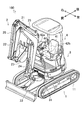
- FIG. The perspective view showing a construction machine.
- the side view showing a construction machine.
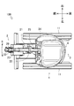
- the top view which shows a construction machine.
- FIG. The figure which shows a selector switch.
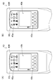
- A The figure which shows the display apparatus in the case where a swing operation is made possible.
- B A figure showing a display in a case where drive of a special work tool is made possible.
- A The figure which shows the display apparatus in, when making a working apparatus swing to right direction.
- backhoe 100 the construction machine (hereinafter referred to as “backhoe”) 100 will be briefly described.
- the technical concept of the present invention can be applied not only to the backhoe 100 described below, but also to other work vehicles.
- FIG. 1 is a perspective view showing the backhoe 100. As shown in FIG. FIG. 2 is a side view thereof, and FIG. 3 is a top view thereof. In the drawings, the front-rear direction and the left-right direction of the backhoe 100 are shown.
- the backhoe 100 mainly includes a traveling device 1, a working device 2, and a turning device 3.
- the travel device 1 travels the backhoe 100.
- the traveling device 1 includes a pair of left and right crawlers 11 and a hydraulic motor 12 and the like.
- the traveling device 1 can move forward and backward by simultaneously driving the left and right crawlers 11 by the hydraulic motor 12.
- the traveling device 1 enables right turn and left turn by the hydraulic motor 12 driving the left and right crawlers 11 independently.
- the work device 2 is for carrying out an excavating work of soil and the like.
- the work device 2 includes a boom 21, an arm 22, a bucket 23 and the like.
- the working device 2 enables the drilling operation by moving these simultaneously or independently.
- the boom 21 is supported at one end thereof by the boom bracket 33 of the turning device 3 and is rotated by the telescopically movable boom cylinder 24.
- one end of the arm 22 is supported by the other end of the boom 21 and is pivoted by the telescopically movable arm cylinder 25.
- One end of the bucket 23 is supported by the other end of the arm 22, and the bucket 23 is pivoted by a telescopically movable bucket cylinder 26.
- the working device 2 enables the digging operation.
- the turning device 3 turns the work device 2.
- the swing device 3 is configured of a swing base 31, a hydraulic motor 32, and the like.
- the turning device 3 enables right turning and left turning by the hydraulic motor 32 driving the turning base 31.
- the pivoting device 3 also includes a boom bracket 33.
- the turning device 3 enables the swing operation of the working device 2 by rotating the boom bracket 33.
- the boom bracket 33 is supported by the swivel base 31 and is pivoted by the telescopically movable swing cylinder 34.
- the turning device 3 enables the swing operation of the working device 2 (see the arrow S in FIG. 3).
- the turning device 3 is provided with a cockpit 4.
- the cockpit 4 is provided with various operation tools 42a, 42b,... In addition to the operation seat 41.
- the operator controls the motors 12 and 32 and the cylinders 24, 25, 26 and 34 by operating the operation tools 42 a and 42 b in a state where the operator is seated on the operation seat 41.
- the operator controls the diesel engine 5 by operating other operation tools.
- the operator maneuvers the backhoe 100.
- the display device 43 is disposed on the right front side of the driver's seat 41 so that the operator can easily view the seat.
- FIG. 4 shows the display device 43.
- the display device 43 includes a lighting display unit 43 a, a liquid crystal display unit 43 b, and a liquid crystal operation unit 43 c.
- the structure of the display device 43 is not limited.
- the lighting display unit 43a represents the driving information of the backhoe 100.
- the lighting display portion 43a displays a plurality of figures in which the driving information of the backhoe 100 is symbolized. Each figure is turned on or off by the backlight. Therefore, the operator can recognize driving information through vision.
- the right swing display unit 43R has an arrow shape pointing to the right side
- the left swing display unit 43L has an arrow shape pointing to the left side.
- the liquid crystal display unit 43 b displays the setting status and the like in addition to the driving information of the backhoe 100.
- the liquid crystal display unit 43 b displays a sentence in which the driving information of the backhoe 100 is described and a symbolized figure. Further, the liquid crystal display unit 43b displays a sentence or a symbolized figure describing the setting condition of the backhoe 100. Therefore, the operator can visually recognize the driving information and the setting situation.
- the liquid crystal operation unit 43c allows the display contents of the liquid crystal display unit 43b to be selectable.
- the liquid crystal operation unit 43c is provided with a plurality of buttons. Then, the control unit switches the display content of the liquid crystal display unit 43b according to the operation of each button. Therefore, the operator can arbitrarily select the display content of the liquid crystal display unit 43b, and can recognize desired operation information and setting conditions.
- the control unit is housed inside the display device 43.
- the selector switch 44 provided in the cockpit 4 will be described.
- the selector switch 44 is disposed on the right of the operator's seat 41 so that the operator can easily operate in a seated state (see FIG. 1).
- the selector switch 44 is effective only when the diesel engine 5 is moving.
- FIG. 5 shows the selector switch 44. Further, FIG. 6A shows the display device 43 when the swing operation is possible, and FIG. 6B shows the display device 43 when the special work tool can be driven. Is shown.
- the selector switch 44 is generally called a rocker switch or a seesaw switch.
- the configuration of the selector switch 44 is not limited.
- the operator can make the swing operation of the working device 2 possible. That is, the operator can select the operation mode in which the swing operation is performed. At this time, the right swing display unit 43R and the left swing display unit 43L of the display device 43 light continuously or intermittently (see FIG. 6A).
- the operator can drive the special work tool attached to the work apparatus 2 (FIG. 5 shows that the X side is pressed). Note). That is, the operator can select an operation mode for driving the special work tool. At this time, the right swing display unit 43R and the left swing display unit 43L of the display device 43 remain unlit (see FIG. 6B).
- the display device 43 displays that the selector switch 44 has selected the swing operation.
- the display device 43 displays that the selector switch 44 has selected the swing operation.
- the swing switch 45 provided in the cockpit 4 will be described.
- the swing switch 45 is disposed on the upper portion of the operation tool 42a so that the operator can quickly operate while steering (see FIG. 7).
- the swing switch 45 is effective only when the selector switch 44 selects the swing operation.
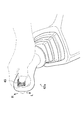
- FIG. 7 shows the swing switch 45.
- 8A shows the display device 43 in the case of swinging the work device 2 to the right
- FIG. 8B shows the display device in the case of swinging the work device 2 to the left 43 is shown.
- the swing switch 45 is generally called a lever switch.
- the structure of the swing switch 45 is not limited.
- the operator can realize the swing operation to the right of the work device 2 by tilting the swing switch 45 to the R side. That is, the operator can turn the working device 2 to the right. At this time, the right swing display unit 43R of the display device 43 is turned on continuously or intermittently, and the left swing display unit 43L is turned off (see FIG. 8A).
- the operator can realize the swing operation to the left of the working device 2 by tilting the swing switch 45 to the L side. That is, the operator can turn the working device 2 to the left.
- the left swing display unit 43L of the display device 43 is turned on continuously or intermittently, and the right swing display unit 43R is turned off (see FIG. 8B).
- the display device 43 displays that the swing switch 45 selects the swing operation to the right or selects the swing operation to the left.
- the safety can be improved.
- the backhoe 100 includes a selector switch 44. Then, the display device 43 displays that the selector switch 44 has selected the swing operation. Specifically, the right swing display unit 43R and the left swing display unit 43L light continuously or intermittently.
- the backhoe 100 includes a swing switch 45. Then, the display device 43 displays that the swing switch 45 selects the swing operation to the right or selects the swing operation to the left. Specifically, the right swing display unit 43R is turned on continuously or intermittently and the left swing display unit 43L is turned off. Alternatively, the left swing display unit 43L is turned on continuously or intermittently and the right swing display unit 43R is turned off.
- the selector switch 44 selects the swing operation
- the right swing display unit 43R and the left swing display unit 43L light continuously or intermittently.
- the swing switch 45 selects the swing operation to the right
- the right swing display unit 43R lights continuously or intermittently and the left swing display unit 43L is turned off, and the swing switch 45 moves to the left.
- the left swing display unit 43L is turned on continuously or intermittently and the right swing display unit 43R is turned off.
- the display device 43 is controlled as follows in order to enhance the above effect.
- the display device 43 intermittently lights the right swing display unit 43R and the left swing display unit 43L when the selector switch 44 selects the swing operation. This is to alert the operator that the operation mode is a swing operation.
- the display device 43 continuously turns on the right swing display unit 43R and turns off the left swing display unit 43L, and the swing switch 45 When the swing operation to the left is selected, the left swing display unit 43L is continuously turned on and the right swing display unit 43R is turned off. This is to clearly indicate the direction in which the working device 2 turns and to alert the operator about the direction in which the working device 2 turns.
- this backhoe 100 when the selector switch 44 selects the swing operation, the right swing display section 43R and the left swing display section 43L are lit, but the other display sections are lit. Also good. Further, in the present backhoe 100, the right swing display portion 43R and the left swing display portion 43L are turned off when the selector switch 44 selects the driving of the special work tool, but the other display portions are turned on. It is good.
- the backhoe 100 includes an alarm buzzer 46 inside the instrument panel.
- the alarm buzzer 46 is interlocked with the selector switch 44, and continues to emit an alarm sound as long as the selector switch 44 selects the swing operation.
- the alarm buzzer 46 emits an alarm sound continuously or intermittently when the selector switch 44 selects the swing operation.
- the safety can be further improved.
- the present invention is applicable to the technology of construction machinery.
Landscapes
- Engineering & Computer Science (AREA)
- Mining & Mineral Resources (AREA)
- Civil Engineering (AREA)
- General Engineering & Computer Science (AREA)
- Structural Engineering (AREA)
- Mechanical Engineering (AREA)
- Component Parts Of Construction Machinery (AREA)
Abstract
スイング動作を可能とする作業装置2と、運転情報の表示を可能とする表示装置43と、を備えた建設機械(バックホー100)において、前記作業装置2のスイング動作を可能な状態とするか前記作業装置2に取り付けられた特殊作業具の駆動を可能な状態とするかを選択できるセレクタスイッチ44を具備し、前記表示装置43は、前記セレクタスイッチ44がスイング動作を選択している旨を表示する、とした。
Description
本発明は、建設機械の技術に関する。
従来より、土砂等の掘削作業に用いられる建設機械が知られている(例えば特許文献1参照)。このような建設機械は、油圧によって可動する作業装置を備えている。作業装置には、土砂等を掘削してすくい上げるバケットが取り付けられている。
ところで、作業装置に取り付け可能とした特殊作業具が知られている(例えば特許文献2参照)。例えばブレーカーやカッター、フォーククロー等である。このような特殊作業具は、バケットの代わりに取り付けられ、PTO機構の油圧によって駆動する。
また、近年の建設機械では、作業装置のスイング動作を可能としている(例えば特許文献3参照)。「スイング動作」とは、作業装置のみを左右に旋回させる動きをいう。このような建設機械は、PTO機構の油圧を利用してスイング動作を可能としている。従って、作業装置のスイング動作と作業装置に取り付けられた特殊作業具の駆動は、同時に行なうことができないのである。
以上のような建設機械において、オペレータは、作業装置のスイング動作を可能な状態とするか、作業装置に取り付けられた特殊作業具の駆動を可能な状態とするか、を選択する。また、オペレータは、作業装置を右方へスイング動作させるか、作業装置を左方へスイング動作させるか、を選択する。そのため、オペレータが自己の選択を視覚又は聴覚にて確認できれば、安全性の向上に寄与するものと考えられる。
本発明は、オペレータが自己の選択を確認できる建設機械を提供することを目的としている。
本発明の第一の態様は、
スイング動作を可能とする作業装置と、
運転情報の表示を可能とする表示装置と、を備えた建設機械において、
前記作業装置のスイング動作を可能な状態とするか前記作業装置に取り付けられた特殊作業具の駆動を可能な状態とするかを選択できるセレクタスイッチを具備し、
前記表示装置は、前記セレクタスイッチがスイング動作を選択している旨を表示する、としたものである。
スイング動作を可能とする作業装置と、
運転情報の表示を可能とする表示装置と、を備えた建設機械において、
前記作業装置のスイング動作を可能な状態とするか前記作業装置に取り付けられた特殊作業具の駆動を可能な状態とするかを選択できるセレクタスイッチを具備し、
前記表示装置は、前記セレクタスイッチがスイング動作を選択している旨を表示する、としたものである。
本発明の第二の態様は、第一の態様に係る建設機械において、
前記作業装置を右方へスイング動作させるか前記作業装置を左方へスイング動作させるかを選択できるスイングスイッチを具備し、
前記表示装置は、前記スイングスイッチが右方へのスイング動作を選択している又は左方へのスイング動作を選択している旨を表示する、としたものである。
前記作業装置を右方へスイング動作させるか前記作業装置を左方へスイング動作させるかを選択できるスイングスイッチを具備し、
前記表示装置は、前記スイングスイッチが右方へのスイング動作を選択している又は左方へのスイング動作を選択している旨を表示する、としたものである。
本発明の第三の態様は、第二の態様に係る建設機械において、
前記表示装置は、
右方へのスイング動作を表示する右スイング表示部と、
左方へのスイング動作を表示する左スイング表示部と、を具備し、
前記セレクタスイッチがスイング動作を選択している場合では、前記右スイング表示部と前記左スイング表示部が連続的又は間欠的に点灯し、
前記スイングスイッチが右方へのスイング動作を選択しているときには、前記右スイング表示部が連続的又は間欠的に点灯するとともに前記左スイング表示部を消灯し、
前記スイングスイッチが左方へのスイング動作を選択しているときには、前記左スイング表示部が連続的又は間欠的に点灯するとともに前記右スイング表示部を消灯する、としたものである。
前記表示装置は、
右方へのスイング動作を表示する右スイング表示部と、
左方へのスイング動作を表示する左スイング表示部と、を具備し、
前記セレクタスイッチがスイング動作を選択している場合では、前記右スイング表示部と前記左スイング表示部が連続的又は間欠的に点灯し、
前記スイングスイッチが右方へのスイング動作を選択しているときには、前記右スイング表示部が連続的又は間欠的に点灯するとともに前記左スイング表示部を消灯し、
前記スイングスイッチが左方へのスイング動作を選択しているときには、前記左スイング表示部が連続的又は間欠的に点灯するとともに前記右スイング表示部を消灯する、としたものである。
本発明の第四の態様は、第三の態様に係る建設機械において、
前記セレクタスイッチがスイング動作を選択している場合では、前記右スイング表示部と前記左スイング表示部が間欠的に点灯し、
前記スイングスイッチが右方へのスイング動作を選択しているときには、前記右スイング表示部が連続的に点灯するとともに前記左スイング表示部を消灯し、
前記スイングスイッチが左方へのスイング動作を選択しているときには、前記左スイング表示部が連続的に点灯するとともに前記右スイング表示部を消灯する、としたものである。
前記セレクタスイッチがスイング動作を選択している場合では、前記右スイング表示部と前記左スイング表示部が間欠的に点灯し、
前記スイングスイッチが右方へのスイング動作を選択しているときには、前記右スイング表示部が連続的に点灯するとともに前記左スイング表示部を消灯し、
前記スイングスイッチが左方へのスイング動作を選択しているときには、前記左スイング表示部が連続的に点灯するとともに前記右スイング表示部を消灯する、としたものである。
本発明の第五の態様は、第一から第四のいずれかに係る建設機械において、
警報ブザーを具備し、
前記警報ブザーは、前記セレクタスイッチがスイング動作を選択している場合に、連続的又は間欠的に警報音を発する、としたものである。
警報ブザーを具備し、
前記警報ブザーは、前記セレクタスイッチがスイング動作を選択している場合に、連続的又は間欠的に警報音を発する、としたものである。
本発明の効果として、以下に示すような効果を奏する。
本発明の第一の態様によれば、表示装置は、セレクタスイッチがスイング動作を選択している旨を表示する。これにより、本建設機械は、オペレータがスイング動作の選択を確認できるので、安全性を向上させることが可能となる。
本発明の第二の態様によれば、表示装置は、スイングスイッチが右方へのスイング動作を選択している又は左方へのスイング動作を選択している旨を表示する。これにより、本建設機械は、オペレータがスイング動作の方向を確認できるので、安全性を向上させることが可能となる。
本発明の第三の態様によれば、セレクタスイッチがスイング動作を選択している場合では、右スイング表示部と左スイング表示部が連続的又は間欠的に点灯する。また、スイングスイッチが右方へのスイング動作を選択しているときには、右スイング表示部が連続的又は間欠的に点灯するとともに左スイング表示部を消灯し、スイングスイッチが左方へのスイング動作を選択しているときには、左スイング表示部が連続的又は間欠的に点灯するとともに右スイング表示部を消灯する。これにより、本建設機械は、オペレータがスイング動作の選択やスイング動作の方向を確認しやすいので、更に安全性を向上させることが可能となる。
本発明の第四の態様によれば、セレクタスイッチがスイング動作を選択している場合では、右スイング表示部と左スイング表示部が間欠的に点灯する。また、スイングスイッチが右方へのスイング動作を選択しているときには、右スイング表示部が連続的に点灯するとともに左スイング表示部を消灯し、スイングスイッチが左方へのスイング動作を選択しているときには、左スイング表示部が連続的に点灯するとともに右スイング表示部を消灯する。これにより、本建設機械は、オペレータがスイング動作の選択やスイング動作の方向をより確認しやすいので、更に安全性を向上させることが可能となる。
本発明の第五の態様によれば、警報ブザーは、セレクタスイッチがスイング動作を選択している場合に、連続的又は間欠的に警報音を発する。これにより、本建設機械は、オペレータがスイング動作の選択を確認できるので、更に安全性を向上させることが可能となる。
次に、発明の実施の形態を説明する。
まず、建設機械(以降「バックホー」とする)100について簡単に説明する。なお、本発明の技術的思想は、以下に説明するバックホー100に限らず、他の作業車両にも適用することが可能である。
図1は、バックホー100を示す斜視図である。また、図2は、その側面図であり、図3は、その上面図である。なお、図中には、バックホー100の前後方向及び左右方向を表している。
図1から図3に示すように、バックホー100は、主に走行装置1と、作業装置2と、旋回装置3と、で構成されている。
走行装置1は、バックホー100を走行させるものである。走行装置1は、左右一対のクローラ11や油圧モータ12等で構成される。走行装置1は、油圧モータ12が左右のクローラ11を同時に駆動することで前進及び後進を可能としている。また、走行装置1は、油圧モータ12が左右のクローラ11を独立して駆動することで右旋回及び左旋回を可能としている。
作業装置2は、土砂等の掘削作業を行なうものである。作業装置2は、ブーム21やアーム22、バケット23等で構成される。作業装置2は、これらを同時に又は独立して動かすことで掘削作業を可能としている。具体的に説明すると、ブーム21は、その一端部が旋回装置3のブームブラケット33に支持されており、伸縮自在に可動するブームシリンダ24によって回動される。また、アーム22は、その一端部がブーム21の他端部に支持されており、伸縮自在に可動するアームシリンダ25によって回動される。そして、バケット23は、その一端部がアーム22の他端部に支持されており、伸縮自在に可動するバケットシリンダ26によって回動される。こうして、作業装置2は、掘削作業を可能としているのである。
旋回装置3は、作業装置2を旋回させるものである。旋回装置3は、旋回台31や油圧モータ32等で構成される。旋回装置3は、油圧モータ32が旋回台31を駆動することで右旋回及び左旋回を可能としている。また、旋回装置3は、ブームブラケット33を備えている。旋回装置3は、ブームブラケット33を回動させることで作業装置2のスイング動作を可能としている。具体的に説明すると、ブームブラケット33は、旋回台31に支持されており、伸縮自在に可動するスイングシリンダ34によって回動される。こうして、旋回装置3は、作業装置2のスイング動作を可能としているのである(図3の矢印S参照)。
加えて、旋回装置3には、コクピット4が設けられている。コクピット4には、操縦席41のほか、各種の操作具42a・42b・・・が備えられている。オペレータは、操縦席41に着座した状態で操作具42a・42b・・・を操作することによって各モータ12・32や各シリンダ24・25・26・34の制御を行なう。また、オペレータは、他の操作具を操作することによってディーゼルエンジン5の制御を行なう。こうして、オペレータは、バックホー100を操縦するのである。
次に、コクピット4に備えられている表示装置43について説明する。表示装置43は、オペレータが着座した状態で容易に見ることができるよう、操縦席41の右前方に配置されている。
図4は、表示装置43を示している。
図4に示すように、表示装置43は、点灯表示部43a、液晶表示部43b、及び液晶操作部43cで構成されている。但し、表示装置43の構造形態について限定するものではない。
点灯表示部43aは、バックホー100の運転情報を表す。点灯表示部43aには、バックホー100の運転情報を記号化した複数の図形が表示されている。また、各図形は、バックライトによって点灯又は消灯する。従って、オペレータは、視覚を通じて運転情報を認識できるのである。なお、右スイング表示部43Rは、右側を指した矢印形状であり、左スイング表示部43Lは、左側を指した矢印形状である。
液晶表示部43bは、バックホー100の運転情報のほか、設定状況等を表示する。液晶表示部43bには、バックホー100の運転情報を記した文章や記号化した図形が表示される。また、液晶表示部43bには、バックホー100の設定状況を記した文章や記号化した図形が表示される。従って、オペレータは、視覚を通じて運転情報ならびに設定状況を認識できるのである。
液晶操作部43cは、液晶表示部43bの表示内容を選択自在とする。液晶操作部43cには、複数のボタンが設けられている。そして、制御部は、液晶表示部43bの表示内容を各ボタンの操作に応じて切り替える。従って、オペレータは、任意に液晶表示部43bの表示内容を選択し、所望の運転情報ならびに設定状況を認識できるのである。なお、制御部は、表示装置43の内部に納められている。
次に、コクピット4に備えられているセレクタスイッチ44について説明する。セレクタスイッチ44は、オペレータが着座した状態で容易に操作できるよう、操縦席41の右方に配置されている(図1参照)。セレクタスイッチ44は、ディーゼルエンジン5が可動している場合のみ有効となる。
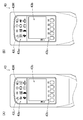
図5は、セレクタスイッチ44を示している。また、図6(A)は、スイング動作を可能な状態とした場合における表示装置43を示しており、図6(B)は、特殊作業具の駆動を可能な状態とした場合における表示装置43を示している。
図5に示すように、セレクタスイッチ44は、一般的にロッカースイッチやシーソースイッチと呼ばれるものである。但し、セレクタスイッチ44の構造形態について限定するものではない。
オペレータは、セレクタスイッチ44のX側を押すことで、作業装置2のスイング動作を可能な状態にできる。即ち、オペレータは、スイング動作を行なうオペレーションモードを選択できる。このとき、表示装置43の右スイング表示部43Rと左スイング表示部43Lは、連続的又は間欠的に点灯する(図6(A)参照)。
他方、オペレータは、セレクタスイッチ44のY側を押すことで、作業装置2に取り付けられた特殊作業具の駆動を可能な状態にできる(図5はX側を押した状態を表していることに注意)。即ち、オペレータは、特殊作業具の駆動を行なうオペレーションモードを選択できる。このとき、表示装置43の右スイング表示部43Rと左スイング表示部43Lは、消灯したままとなる(図6(B)参照)。
このように、表示装置43は、セレクタスイッチ44がスイング動作を選択している旨を表示する。これにより、本バックホー100は、オペレータがスイング動作の選択を確認できるので、安全性を向上させることが可能となる。
次に、コクピット4に備えられているスイングスイッチ45について説明する。スイングスイッチ45は、オペレータが操縦しながら素早く操作できるよう、操作具42aの上部に配置されている(図7参照)。スイングスイッチ45は、セレクタスイッチ44がスイング動作を選択している場合のみ有効となる。
図7は、スイングスイッチ45を示している。また、図8(A)は、作業装置2を右方へスイング動作させる場合における表示装置43を示しており、図8(B)は、作業装置2を左方へスイング動作させる場合における表示装置43を示している。
図7に示すように、スイングスイッチ45は、一般的にレバースイッチと呼ばれるものである。但し、スイングスイッチ45の構造形態について限定するものではない。
オペレータは、スイングスイッチ45をR側に倒すことで、作業装置2の右方へのスイング動作を実現できる。即ち、オペレータは、作業装置2を右方へ旋回させることができる。このとき、表示装置43の右スイング表示部43Rは、連続的又は間欠的に点灯し、左スイング表示部43Lは、消灯したままとなる(図8(A)参照)。
他方、オペレータは、スイングスイッチ45をL側に倒すことで、作業装置2の左方へのスイング動作を実現できる。即ち、オペレータは、作業装置2を左方へ旋回させることができる。このとき、表示装置43の左スイング表示部43Lは、連続的又は間欠的に点灯し、右スイング表示部43Rは、消灯したままとなる(図8(B)参照)。
このように、表示装置43は、スイングスイッチ45が右方へのスイング動作を選択している又は左方へのスイング動作を選択している旨を表示する。これにより、本バックホー100は、オペレータがスイング動作の方向を確認できるので、安全性を向上させることが可能となる。
以上より、本バックホー100に適用した技術的特徴をまとめると次のようになる。
第一の特徴として、本バックホー100は、セレクタスイッチ44を備えている。そして、表示装置43は、セレクタスイッチ44がスイング動作を選択している旨を表示する。具体的には、右スイング表示部43Rと左スイング表示部43Lが連続的又は間欠的に点灯する。
第二の特徴として、本バックホー100は、スイングスイッチ45を備えている。そして、表示装置43は、スイングスイッチ45が右方へのスイング動作を選択している又は左方へのスイング動作を選択している旨を表示する。具体的には、右スイング表示部43Rが連続的又は間欠的に点灯するとともに左スイング表示部43Lを消灯したままとする。若しくは、左スイング表示部43Lが連続的又は間欠的に点灯するとともに右スイング表示部43Rを消灯したままとする。
このように、セレクタスイッチ44がスイング動作を選択している場合では、右スイング表示部43Rと左スイング表示部43Lが連続的又は間欠的に点灯する。また、スイングスイッチ45が右方へのスイング動作を選択しているときには、右スイング表示部43Rが連続的又は間欠的に点灯するとともに左スイング表示部43Lを消灯し、スイングスイッチ45が左方へのスイング動作を選択しているときには、左スイング表示部43Lが連続的又は間欠的に点灯するとともに右スイング表示部43Rを消灯する。これにより、本バックホー100は、オペレータがスイング動作の選択やスイング動作の方向を確認しやすいので、更に安全性を向上させることが可能となる。
なお、表示装置43は、上記の効果を高めるために次のように制御している。
即ち、表示装置43は、セレクタスイッチ44がスイング動作を選択している場合に、右スイング表示部43Rと左スイング表示部43Lを間欠的に点灯する。これは、スイング動作を行なうオペレーションモードであることについて、オペレータに注意を喚起するためである。
また、表示装置43は、スイングスイッチ45が右方へのスイング動作を選択しているときに、右スイング表示部43Rが連続的に点灯するとともに左スイング表示部43Lを消灯し、スイングスイッチ45が左方へのスイング動作を選択しているときに、左スイング表示部43Lが連続的に点灯するとともに右スイング表示部43Rを消灯する。これは、作業装置2が旋回する方向を明確に示し、該作業装置2が旋回する方向について、オペレータに注意を喚起するためである。
留意事項として、本バックホー100においては、セレクタスイッチ44がスイング動作を選択している場合に、右スイング表示部43Rと左スイング表示部43Lを点灯するとしているが、他の表示部を点灯させても良い。また、本バックホー100においては、セレクタスイッチ44が特殊作業具の駆動を選択している場合に、右スイング表示部43Rと左スイング表示部43Lを消灯するとしているが、他の表示部を点灯させても良い。
次に、本バックホー100の他の特徴点について説明する。
図2に示すように、本バックホー100は、インストルメントパネルの内側に警報ブザー46を備えている。警報ブザー46は、セレクタスイッチ44に連動しており、該セレクタスイッチ44がスイング動作を選択している限り、警報音を発し続ける。
このように、警報ブザー46は、セレクタスイッチ44がスイング動作を選択している場合に、連続的又は間欠的に警報音を発する。これにより、本バックホー100は、オペレータがスイング動作の選択を確認できるので、更に安全性を向上させることが可能となる。
本発明は、建設機械の技術に利用可能である。
100 バックホー(建設機械)
1 走行装置
11 クローラ
12 油圧モータ
2 作業装置
21 ブーム
22 アーム
23 バケット
3 旋回装置
31 旋回台
32 油圧モータ
33 ブームブラケット
34 スイングシリンダ
4 コクピット
41 操縦席
42a 操作具
42b 操作具
43 表示装置
43a 点灯表示部
43b 液晶表示部
43c 液晶操作部
43R 右スイング表示部
43L 左スイング表示部
44 セレクトスイッチ
45 スイングスイッチ
46 警報ブザー
5 ディーゼルエンジン
1 走行装置
11 クローラ
12 油圧モータ
2 作業装置
21 ブーム
22 アーム
23 バケット
3 旋回装置
31 旋回台
32 油圧モータ
33 ブームブラケット
34 スイングシリンダ
4 コクピット
41 操縦席
42a 操作具
42b 操作具
43 表示装置
43a 点灯表示部
43b 液晶表示部
43c 液晶操作部
43R 右スイング表示部
43L 左スイング表示部
44 セレクトスイッチ
45 スイングスイッチ
46 警報ブザー
5 ディーゼルエンジン
Claims (5)
- スイング動作を可能とする作業装置と、
運転情報の表示を可能とする表示装置と、を備えた建設機械において、
前記作業装置のスイング動作を可能な状態とするか前記作業装置に取り付けられた特殊作業具の駆動を可能な状態とするかを選択できるセレクタスイッチを具備し、
前記表示装置は、前記セレクタスイッチがスイング動作を選択している旨を表示する、ことを特徴とする建設機械。 - 前記作業装置を右方へスイング動作させるか前記作業装置を左方へスイング動作させるかを選択できるスイングスイッチを具備し、
前記表示装置は、前記スイングスイッチが右方へのスイング動作を選択している又は左方へのスイング動作を選択している旨を表示する、ことを特徴とする請求項1に記載の建設機械。 - 前記表示装置は、
右方へのスイング動作を表示する右スイング表示部と、
左方へのスイング動作を表示する左スイング表示部と、を具備し、
前記セレクタスイッチがスイング動作を選択している場合では、前記右スイング表示部と前記左スイング表示部が連続的又は間欠的に点灯し、
前記スイングスイッチが右方へのスイング動作を選択しているときには、前記右スイング表示部が連続的又は間欠的に点灯するとともに前記左スイング表示部を消灯し、
前記スイングスイッチが左方へのスイング動作を選択しているときには、前記左スイング表示部が連続的又は間欠的に点灯するとともに前記右スイング表示部を消灯する、ことを特徴とする請求項2に記載の建設機械。 - 前記セレクタスイッチがスイング動作を選択している場合では、前記右スイング表示部と前記左スイング表示部が間欠的に点灯し、
前記スイングスイッチが右方へのスイング動作を選択しているときには、前記右スイング表示部が連続的に点灯するとともに前記左スイング表示部を消灯し、
前記スイングスイッチが左方へのスイング動作を選択しているときには、前記左スイング表示部が連続的に点灯するとともに前記右スイング表示部を消灯する、ことを特徴とする請求項3に記載の建設機械。 - 警報ブザーを具備し、
前記警報ブザーは、前記セレクタスイッチがスイング動作を選択している場合に、連続的又は間欠的に警報音を発する、ことを特徴とする請求項1から請求項4のいずれか一項に記載の建設機械。
Applications Claiming Priority (2)
| Application Number | Priority Date | Filing Date | Title |
|---|---|---|---|
| JP2013158141A JP6340175B2 (ja) | 2013-07-30 | 2013-07-30 | 建設機械 |
| JP2013-158141 | 2013-07-30 |
Publications (1)
| Publication Number | Publication Date |
|---|---|
| WO2015016134A1 true WO2015016134A1 (ja) | 2015-02-05 |
Family
ID=52431670
Family Applications (1)
| Application Number | Title | Priority Date | Filing Date |
|---|---|---|---|
| PCT/JP2014/069572 Ceased WO2015016134A1 (ja) | 2013-07-30 | 2014-07-24 | 建設機械 |
Country Status (2)
| Country | Link |
|---|---|
| JP (1) | JP6340175B2 (ja) |
| WO (1) | WO2015016134A1 (ja) |
Cited By (1)
| Publication number | Priority date | Publication date | Assignee | Title |
|---|---|---|---|---|
| US11738673B2 (en) * | 2018-12-06 | 2023-08-29 | Kubota Corporation | Working vehicle |
Citations (2)
| Publication number | Priority date | Publication date | Assignee | Title |
|---|---|---|---|---|
| JPH07138994A (ja) * | 1993-11-15 | 1995-05-30 | Hitachi Constr Mach Co Ltd | 建設機械の作業用表示モニタ |
| JP2004043168A (ja) * | 2002-07-15 | 2004-02-12 | Komatsu Ltd | スイング式油圧ショベルの制御装置 |
Family Cites Families (3)
| Publication number | Priority date | Publication date | Assignee | Title |
|---|---|---|---|---|
| JPH1060947A (ja) * | 1996-08-21 | 1998-03-03 | Komatsu Ltd | 油圧ショベルの操作装置 |
| JP3841209B2 (ja) * | 2002-08-15 | 2006-11-01 | 東日本旅客鉄道株式会社 | 構造用鋼材の継手構造 |
| US8521371B2 (en) * | 2010-12-22 | 2013-08-27 | Caterpillar Inc. | Systems and methods for remapping of machine implement controls |
-
2013
- 2013-07-30 JP JP2013158141A patent/JP6340175B2/ja active Active
-
2014
- 2014-07-24 WO PCT/JP2014/069572 patent/WO2015016134A1/ja not_active Ceased
Patent Citations (2)
| Publication number | Priority date | Publication date | Assignee | Title |
|---|---|---|---|---|
| JPH07138994A (ja) * | 1993-11-15 | 1995-05-30 | Hitachi Constr Mach Co Ltd | 建設機械の作業用表示モニタ |
| JP2004043168A (ja) * | 2002-07-15 | 2004-02-12 | Komatsu Ltd | スイング式油圧ショベルの制御装置 |
Cited By (1)
| Publication number | Priority date | Publication date | Assignee | Title |
|---|---|---|---|---|
| US11738673B2 (en) * | 2018-12-06 | 2023-08-29 | Kubota Corporation | Working vehicle |
Also Published As
| Publication number | Publication date |
|---|---|
| JP6340175B2 (ja) | 2018-06-06 |
| JP2015028272A (ja) | 2015-02-12 |
Similar Documents
| Publication | Publication Date | Title |
|---|---|---|
| US9670939B2 (en) | Operation control system | |
| EP2105536B1 (en) | Display Device of Work Vehicle | |
| EP2105339B1 (en) | Display Device of Work Vehicle | |
| WO2012176499A1 (ja) | 作業車両、作業車両用表示装置、作業車両用表示装置の制御方法、バックホウローダ、バックホウローダ用表示装置、およびバックホウローダ用表示装置の制御方法 | |
| JP5669520B2 (ja) | 作業車両 | |
| JP2005155274A (ja) | 建設機械の表示装置 | |
| JP2016071426A (ja) | 走行作業車の操縦補助装置 | |
| JP6340175B2 (ja) | 建設機械 | |
| JP6113046B2 (ja) | トラクタ | |
| CN111051614A (zh) | 作业车辆 | |
| JP2007120222A (ja) | ホイール式建設機械 | |
| JP5781971B2 (ja) | 作業車両 | |
| JP2024113876A (ja) | 作業機械 | |
| JP4690352B2 (ja) | 建設機械の走行制御装置 | |
| EP3048505B1 (en) | Device for operating the double arm of a working machine | |
| WO2025197261A1 (ja) | 作業車 | |
| JP6198557B2 (ja) | トラクタ | |
| CN119365656A (zh) | 工程机械 | |
| JP2008008122A (ja) | 建設機械のモニタ | |
| JP2009097303A (ja) | 建設機械 | |
| JP2025041061A (ja) | 作業機械および作業機械の制御方法 | |
| GB2641779A (en) | Working machine | |
| KR20230067262A (ko) | 건설 기계 | |
| JP2003291865A (ja) | クローラ型作業車輛 | |
| JP2024052153A (ja) | 建設機械 |
Legal Events
| Date | Code | Title | Description |
|---|---|---|---|
| 121 | Ep: the epo has been informed by wipo that ep was designated in this application |
Ref document number: 14831899 Country of ref document: EP Kind code of ref document: A1 |
|
| NENP | Non-entry into the national phase |
Ref country code: DE |
|
| 122 | Ep: pct application non-entry in european phase |
Ref document number: 14831899 Country of ref document: EP Kind code of ref document: A1 |