WO2015015968A1 - 往復運動工具 - Google Patents
往復運動工具 Download PDFInfo
- Publication number
- WO2015015968A1 WO2015015968A1 PCT/JP2014/067145 JP2014067145W WO2015015968A1 WO 2015015968 A1 WO2015015968 A1 WO 2015015968A1 JP 2014067145 W JP2014067145 W JP 2014067145W WO 2015015968 A1 WO2015015968 A1 WO 2015015968A1
- Authority
- WO
- WIPO (PCT)
- Prior art keywords
- plunger
- reciprocating
- guide portion
- guide
- power
- Prior art date
- Legal status (The legal status is an assumption and is not a legal conclusion. Google has not performed a legal analysis and makes no representation as to the accuracy of the status listed.)
- Ceased
Links
Images


Classifications
-
- B—PERFORMING OPERATIONS; TRANSPORTING
- B23—MACHINE TOOLS; METAL-WORKING NOT OTHERWISE PROVIDED FOR
- B23D—PLANING; SLOTTING; SHEARING; BROACHING; SAWING; FILING; SCRAPING; LIKE OPERATIONS FOR WORKING METAL BY REMOVING MATERIAL, NOT OTHERWISE PROVIDED FOR
- B23D49/00—Machines or devices for sawing with straight reciprocating saw blades, e.g. hacksaws
- B23D49/10—Hand-held or hand-operated sawing devices with straight saw blades
- B23D49/16—Hand-held or hand-operated sawing devices with straight saw blades actuated by electric or magnetic power or prime movers
- B23D49/162—Pad sawing devices
-
- B—PERFORMING OPERATIONS; TRANSPORTING
- B23—MACHINE TOOLS; METAL-WORKING NOT OTHERWISE PROVIDED FOR
- B23D—PLANING; SLOTTING; SHEARING; BROACHING; SAWING; FILING; SCRAPING; LIKE OPERATIONS FOR WORKING METAL BY REMOVING MATERIAL, NOT OTHERWISE PROVIDED FOR
- B23D51/00—Sawing machines or sawing devices working with straight blades, characterised only by constructional features of particular parts; Carrying or attaching means for tools, covered by this subclass, which are connected to a carrier at both ends
- B23D51/16—Sawing machines or sawing devices working with straight blades, characterised only by constructional features of particular parts; Carrying or attaching means for tools, covered by this subclass, which are connected to a carrier at both ends of drives or feed mechanisms for straight tools, e.g. saw blades, or bows
- B23D51/161—Sawing machines or sawing devices working with straight blades, characterised only by constructional features of particular parts; Carrying or attaching means for tools, covered by this subclass, which are connected to a carrier at both ends of drives or feed mechanisms for straight tools, e.g. saw blades, or bows with dynamic balancing
Definitions
- the present invention relates to a reciprocating tool for reciprocating an operation member with the power of a power source.
- a reciprocating tool described in Patent Document 1 includes an electric motor provided inside a tool body, a gear to which the rotational force of the electric motor is transmitted, an eccentric portion provided eccentrically from the rotation center of the gear, and an eccentricity. And a balance weight having a long hole in which the portion is movably disposed.
- a reciprocating tool described in Patent Document 1 includes a pin provided at a position eccentric from the rotation center of a gear, a sleeve rotatably attached to the pin, and a plunger provided inside the tool body so as to be capable of reciprocating. And a sleeve guide that is provided on the plunger and guides the sleeve, and a tip tool attached to the plunger.
- the plunger and sleeve guide described in Patent Document 1 will be specifically described with reference to FIG.
- the plunger 100 is movable along the center line A1, that is, ascends and descends.
- the sleeve guide 101 is fixed to the plunger 100.
- the sleeve guide 101 has a pair of guide portions 102 and 103 extended in a direction intersecting the center line A1.
- the pair of guide portions 102 and 103 are parallel to each other.
- the sleeve 104 is disposed between the guide portion 102 and the guide portion 103 so as to be able to roll.
- the sleeve 104 revolves in a circular shape outside the rotation center of the gear.
- the moving force of the sleeve 104 is transmitted to the guide portion 102 and the plunger 100 is raised.
- the moving force of the sleeve 104 is transmitted to the guide portion 103 and the plunger 100 descends. In this way, the object is processed by repeating the operation of raising and lowering the tip tool together with the plunger 100.
- the balance weight moves in the direction along the center line A1.
- the direction in which the balance weight moves is opposite to the direction in which the plunger and the tip tool move. In this way, the balance weight moves in a phase opposite to that of the plunger and the tip tool, so that the vibration due to the reciprocating motion of the plunger and the tip tool is canceled, and the vibration of the reciprocating tool can be reduced.
- the reciprocating tool described in Patent Document 1 is provided with a sleeve guide that transmits the moving force of the sleeve to the plunger, and the sleeve guide is provided with a pair of guide portions. For this reason, there has been room for improvement in order to reduce the weight of the reciprocating tool. *
- An object of the present invention is to reduce the weight of a reciprocating tool.
- a reciprocating tool is a reciprocating tool that reciprocates an operation member in a first direction with the power of a power source, wherein the power is transmitted from the power source and revolves around a rotation center. And a support portion that supports the operating member and converts the revolving force of the power transmission member into a reciprocating force of the operating member, and the support portion intersects the first direction.
- a first guide portion extending in a second direction, and a second guide portion extending in a second direction intersecting the first direction and parallel to the first guide portion, The power transmission member moves in the second direction between the first guide portion and the second guide portion when revolving around the rotation center, and the power transmission member moves in the second direction.
- Arrangement range and arrangement range of the second guide part in the second direction It is different.
- the arrangement range of the first guide part in the second direction is different from the arrangement range of the second guide part in the second direction, and the weight of the reciprocating tool can be reduced.
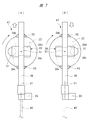
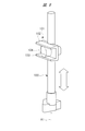
- FIG. (A) to (E) are schematic side views showing the main part of the jigsaw shown in FIG. (A), (B) is a typical side view which shows the principal part of the jigsaw shown in FIG. It is a perspective view which shows the other structural example of the principal part of the jigsaw shown in FIG. (A), (B) is a typical side view of the structural example shown in FIG. It is a perspective view which shows the principal part of the conventional reciprocating tool.
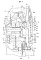
- FIG. 1 is a front sectional view of a jigsaw 11 for cutting the object 10
- FIG. 2 is an enlarged front sectional view of a main part of FIG. 1.
- the object 10 includes wood, mild steel plate, and stainless steel.
- the jigsaw 11 has a tool body 12, and the tool body 12 includes a first cylinder portion 13 that extends in the horizontal direction and a second cylinder portion 14 that extends upward from the end of the first cylinder portion 13. And a handle portion 15 that connects the end portion of the first tube portion 13 and the end portion of the second tube portion 14.
- the horizontal direction is a direction along the surface 10 a of the object 10.
- the center line of the first cylinder part 13 and the center line of the second cylinder part 14 intersect each other.
- the 2nd cylinder part 14 has an opening part, and the cover 14a which covers an opening part is provided. *
- An electric motor 16 is provided in the first cylinder portion 13.
- a pinion 18 is provided on the output shaft 17 of the electric motor 16.
- a gear holder 19 is provided from the first tube portion 13 to the inside of the second tube portion 14, and the bearing 20 attached to the gear holder 19 and the bearing 20A provided on the first tube portion 13 rotate the output shaft 17. I support it as possible.
- a support shaft 21 parallel to the output shaft 17 is fixed to the gear holder 19, and the support shaft 21 supports a gear 22 in a rotatable manner.
- the gear 22 meshes with the pinion 18.
- An eccentric portion 23 is provided continuously to the gear 22.
- the eccentric portion 23 protrudes from the side surface of the gear 22 in a direction along the rotation center B1 of the support shaft 21.
- the outer peripheral shape of the eccentric part 23 is circular, and the center of the eccentric part 23 is eccentric from the rotation center B1.
- a balance weight 24 is attached to the outer periphery of the eccentric portion 23.
- the balance weight 24 is integrally formed of metal.
- the balance weight 24 is provided with a long hole 25 penetrating in the direction along the rotation center B ⁇ b> 1, and the eccentric portion 23 is disposed in the long hole 25.
- the long axis of the long hole 25 is extended along the horizontal direction.
- the eccentric part 23 is movable in the horizontal direction within the long hole 25.
- the balance weight 24 is provided with a linear slit 24a extending in the vertical direction.
- a guide pin 26 is fixed to the gear holder 19, and the guide pin 26 is disposed in the slit 24a.
- the guide pin 26 is movable in the slit 24a, and the guide pin 26 regulates the movement direction of the balance weight 24 in the vertical direction.
- the holder 27 is fixed to the tip of the eccentric part 23 using a screw 28.
- the holder 27 is integrally formed of a steel material.
- a pin 29 is attached to the holder 27.
- the pin 29 is integrally formed of a cylindrical steel material, and the center line C1 of the pin 29 is eccentric from the rotation center B1 of the gear 22.
- a connecting piece 31 is attached to the outer peripheral surface of the pin 29 via a needle bearing 30.
- the connecting piece 31 is formed by integrally forming a steel material into a cylindrical shape.
- a plunger holder 32 is provided in the second cylindrical portion 14.
- a support shaft 32a that supports the upper end of the plunger holder 32 is provided.
- the plunger holder 32 can swing within a range of a predetermined angle.
- the plunger holder 32 is provided with a first shaft hole 33 and a second shaft hole 34 that penetrate in the direction along the center line D1.
- the first shaft hole 33 and the second shaft hole 34 are arranged coaxially, and the center line D1 is arranged along the vertical direction, that is, the vertical direction.
- the center line D1 is perpendicular to the rotation center B1.
- FIG. 1 shows a case where the center line D1 is substantially perpendicular to the surface 10a of the object 10. *
- the plunger holder 32 can swing around the support shaft 32a in a plane parallel to all of the center lines C1 and D1. And the elastic member which urges
- Two stoppers 35 and 43 are fixed to the plunger holder 32.
- the stopper 35 has a third shaft hole 35a, and the stopper 43 has a fourth shaft hole 43a.
- the stopper 35 is fitted in the first shaft hole 33, and the stopper 43 is fitted in the second shaft hole 34.
- the stopper 35 is disposed above the stopper 43 in the direction along the center line D1.
- the stoppers 35 and 43 are integrally formed of a rubber-like elastic body.
- a plunger 36 made of steel is provided inside the tool body 12, and the plunger 36 is movable in the direction along the center line D1 in the third shaft hole 35a and the fourth shaft hole 43a.
- Needle bearings 37 are respectively provided in the first shaft hole 33 and the second shaft hole 34, and the plunger 36 is supported by the two needle bearings 37 so as to be capable of reciprocating in the direction along the center line D1. . *
- the plunger 36 is provided with two recesses 36a in series from both ends in the longitudinal direction along the center line D1.
- a solid portion 36b is provided between the concave portions 36a of the plunger 36, and a connector 38 is fixed to the solid portion 36b.
- the connector 38 is made of steel, and the connector 38 is fixed to the plunger 36 by using a fixing element 44. *
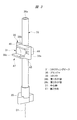
- the connector 38 includes a rectangular plate 38a, and two first guide portions 38b and second guide portions 38c provided along two parallel sides of the plate 38a.
- the first guide portion 38b is provided above the second guide portion 38c in the direction along the center line D1.
- the lower surface of the first guide part 38b is parallel to the upper surface of the second guide part 38c.
- Both the lower surface of the first guide part 38b and the upper surface of the second guide part 38c extend along the second direction E1.
- the second direction E1 in the embodiment is substantially horizontal, and the second direction E1 intersects the center line D1. In the embodiment, the center line D1 and the second direction E1 intersect at a substantially right angle. *
- the first guide portion 38b and the second guide portion 38c have the same length in the second direction E1 within a plane parallel to the center line D1, but are different in the arrangement range in the second direction E1. Specifically, the positions of both ends in the second direction E1 are different between the first guide part 38b and the second guide part 38c.
- a first notch 45 is provided below one end of the first guide portion 38b in a plane parallel to the center line D1. That is, the second guide portion 38c is not provided below one end of the first guide portion 38b.
- a second notch 46 is provided above the other end of the second guide portion 38c in a plane parallel to the center line D1. That is, the first guide portion 38b is not provided above the other end of the second guide portion 38c.
- the second notch 46 is provided on the side of the first guide part 38b, and the first notch 45 is provided on the side of the second guide part 38c.
- the first notch 45 is positioned opposite to the second notch 46.
- the connecting piece 31 is movable along the second direction E1 while being disposed between the lower surface of the first guide portion 38b and the upper surface of the second guide portion 38c.
- the distance between the lower surface of the first guide part 38b and the upper surface of the second guide part 38c in the direction along the center line D1 is slightly larger than the outer diameter of the connecting piece 31.
- the holder 27, the pin 29, the connecting piece 31, and the connector 38 constitute a motion conversion mechanism 47.
- the connector 38 converts the moving force of the connecting piece 31 into the reciprocating motion force of the plunger 36.
- the gear 22 and the holder 27 are provided in a power transmission path from the electric motor 16 to the plunger 36.
- a grip portion 39 is provided at the lower end of the plunger 36, and the blade 40 is gripped by the grip portion 39.
- a base 42 having a flat surface is attached to the second cylindrical portion 14, and an opening 42 a of the base 42 is provided.
- the handle portion 15 is provided with a trigger 15a.
- a power cord 41 is connected to a boundary portion between the handle portion 15 and the first tube portion 13.
- a control unit is provided inside the tool body 12, and the control unit has an electric circuit for connecting the power cord 41 and the electric motor 16, and a switch provided in the electric circuit. The control unit connects or disconnects the switch based on the operation of the trigger 15a.
- the jigsaw 11 has an orbital mechanism.
- the orbital mechanism controls the blade 40 so that the blade 40 has an elliptical movement trajectory as a whole when the plunger 36 moves up and down by swinging the blade 40 within a predetermined angle range with the grip portion 39 as a fulcrum. To do. Specifically, in the process in which the plunger 36 is raised, the blade 40 approaches the object 10, and in the process in which the plunger 36 is lowered, the blade 40 is separated from the object 10. Since the orbital mechanism is a well-known technique as described in Japanese Patent Application Laid-Open Nos. 2002-079417, 2002-283135, and 2006-175524, a specific description thereof is omitted. *
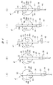
- FIGS. 4 and 5 are schematic side views of the plunger 36 and the gear 22 shown in FIG. 2 as viewed from the cover 14a side.
- the connecting piece 31 is at the lowest position in the direction along the center line D1, and the plunger 36 is at the bottom dead center.
- the gear 22 rotates in the clockwise direction
- the connecting piece 31 revolves around the rotation center B1 as shown in FIGS. 4B to 4E and rises along an arcuate locus.
- the connecting piece 31 is at the highest position in the vertical direction along the center line D1, and the plunger 36 is at the top dead center.
- the rotational force of the gear 22 is transmitted to the balance weight 24, and the balance weight 24 repeats the operation of raising and lowering along the center line D1.
- the direction in which the balance weight 24 operates has a phase opposite to the direction in which the plunger 36 and the blade 40 operate. That is, when the plunger 36 and the blade 40 are raised, the balance weight 24 is lowered. On the other hand, when the plunger 36 and the blade 40 are lowered, the balance weight 24 is raised. For this reason, the vibration by the reciprocating motion of the plunger 36 and the blade 40 is canceled, and the vibration of the jigsaw 11 can be reduced. *
- the stoppers 35 and 43 serve both as a function of regulating the operation range of the plunger 36 and a function of a damper that absorbs an impact.
- a first cutout portion 45 and a second cutout portion 46 are provided in a connector 38 that transmits the moving force of the connecting piece 31 to the plunger 36. That is, the first guide portion 38b is provided within a range in which the connecting piece 31 moves in the second direction E1 while an upward force is transmitted from the connecting piece 31, and the connecting piece 31 is in the second direction E1. The first guide portion 38b is not provided outside the moving range.
- the second guide portion 38c is provided within the range in which the connecting piece 31 moves in the second direction E1 while the downward force is transmitted from the connecting piece 31, and the connecting piece 31 is in the second direction E1. The second guide portion 38c is not provided outside the moving range.
- the weight of the connector 38 reciprocating up and down in the jigsaw 11 can be reduced, and the vibration of the jigsaw 11 can be reduced.
- the mass of the connector 38 can be reduced, the weight of the balance weight 24 that reduces the vibration caused by the reciprocating motion of the plunger 36 and the connector 38 can be reduced. Therefore, the weight of the jigsaw 11 as a whole can be reduced.
- the plunger 36 is provided with a concave portion 36a to reduce the weight of the plunger 36.
- the recess 36a has an inner diameter and a depth in the direction along the center line D1 so that the strength required for the plunger 36 can be maintained when the object 10 is cut by the movement of the plunger 36. Since the mass of the connector 38 is reduced without changing the depth or inner diameter of the recess 36a of the plunger 36, the vibration of the jigsaw 11 can be reduced without reducing the strength of the plunger 36. Furthermore, it is not necessary to use an expensive and lightweight material as the material of the plunger 36. Therefore, it can suppress that the manufacturing cost of the jigsaw 11 rises. *
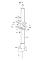
- the connector 38 shown in FIGS. 6 and 7 has a first restricting portion 38d disposed at the same height as the first guide portion 38b and the second notch portion 46.
- the height is a position in the direction along the center line D1.
- the 2nd notch 46 is located in the 2nd direction E1 between the 1st guide part 38b and the 1st control part 38d.
- the connector 38 includes a second restricting portion 38e disposed at the same height as the second guide portion 38c and the first notch portion 45.
- the 1st notch part 45 is located in the 2nd direction E1 between the 2nd guide part 38c and the 2nd control part 38e.
- the second restricting portion 38e is positioned directly below the connecting piece 31 in the second direction E1. ing. For this reason, the 2nd control part 38e contacts the connecting piece 31, and the connector 38 and the connecting piece 31 raise the same position along the centerline D1. That is, it is possible to prevent the connecting piece 31 from being detached from the connector 38.
- the 1st control part 38d contacts the connecting piece 31, and the connector 38 and the connecting piece 31 descend
- the jigsaw 11 can also be used in a state where the center line D1 is inclined with respect to the vertical direction. In this case, the second direction E1 is inclined with respect to the horizontal direction.
- the jigsaw 11 can also cut the object 10 whose surface 10a is not horizontal.
- the jigsaw 11 can also be used when a slit, a cut, or a groove is formed in the object 10. *
- the jigsaw 11 corresponds to the reciprocating tool of the present invention, and the direction along the center line D1 is the first direction of the present invention.
- the pin 29 and the connecting piece 31 correspond to the power transmission member of the present invention
- the plunger 36 and the blade 40 correspond to the operation member of the present invention
- the holder 27 corresponds to the rotating member of the present invention.
- the connector 38 corresponds to the support portion of the present invention
- the blade 40 corresponds to the tip tool of the present invention
- the pinion 18 and the gear 22 correspond to the reduction mechanism of the present invention.
- the reciprocating tool of the present invention is not limited to the above embodiment, and can be variously changed without departing from the gist thereof.
- the power of the battery pack attached to the tool body is supplied to the electric motor in addition to the reciprocating tool in which the power of the commercial power source is supplied to the electric motor via the power cord.
- the battery pack is obtained by housing battery cells in a housing case, and the battery pack is detachable from the tool body.
- the reciprocating tool of the present invention includes a tool in which a gear transmission device, a winding transmission device, and a friction transmission device are provided in a power transmission path from a power source to a rotating member.
- the speed reduction mechanism configured by the pinion 18 and the gear 22 described in the embodiment is a gear transmission.
- the power source that generates power to be transmitted to the tip tool includes an electric motor, an engine, and a hydraulic motor.
- the present invention also includes a reciprocating tool for transmitting the power of the power source to the tip tool, such as a hammer, a hammer driver, a hammer drill, a saver saw, and a hedge trimmer.
Landscapes
- Engineering & Computer Science (AREA)
- Mechanical Engineering (AREA)
- Sawing (AREA)
Abstract
電動モータの動力でプランジャ(36)を中心線(D1)方向に往復運動させるジグソーであって、電動モータからプランジャ(36)に至る動力伝達経路に設けられ、かつ、中心線を中心として回転するギヤ及びホルダと、ホルダに中心線から偏心して設けられ、かつ、中心線の周囲を移動するコネクティングピース(31)と、プランジャ(36)に設けられ、かつ、コネクティングピース(31)の移動力をプランジャ(36)の往復運動力に変換するコネクタ(38)と、コネクタ(38)に設けられ、かつ、中心線(D1)方向に対して交差する第2方向(E1)に沿って平行に配置された第1ガイド部(38b)及び第2ガイド部(38c)と、を有し、第2方向(E1)における第1ガイド部(38b)の配置範囲と、第2方向(E1)における第2ガイド部(38c)の配置範囲とが異なる構成とすることでジグソーの重量を軽減する。
Description
本発明は、動力源の動力で動作部材を往復運動させる往復運動工具に関する。
従来、動力源の動力で、動作部材としての先端工具を往復運動させて対象物を加工する往復運動工具が知られており、その一例が特許文献1に記載されている。特許文献1に記載された往復運動工具は、工具本体の内部に設けた電動モータと、電動モータの回転力が伝達されるギヤと、ギヤの回転中心から偏心して設けられた偏心部と、偏心部が移動可能に配置される長孔を有するバランスウェイトと、を有する。
また、特許文献1に記載された往復運動工具は、ギヤの回転中心から偏心した位置に設けたピンと、ピンに回転可能に取り付けられたスリーブと、工具本体の内部に往復運動可能に設けたプランジャと、プランジャに設けられ、かつ、スリーブをガイドするスリーブガイドと、プランジャに取り付けられた先端工具とを有する。
特許文献1に記載されたプランジャ及びスリーブガイドを、図8により具体的に説明する。プランジャ100は中心線A1に沿って移動可能、つまり、上昇及び下降する。スリーブガイド101は、プランジャ100に固定されている。スリーブガイド101は、中心線A1に対して交差する方向に延ばされた一対のガイド部102,103を有する。一対のガイド部102,103は互いに平行である。スリーブ104は、ガイド部102とガイド部103との間に転動可能に配置されている。
そして、電動モータの回転力でギヤが回転すると、スリーブ104はギヤの回転中心の外側を円形に公転する。ここで、スリーブ104が円弧状に上昇する過程では、スリーブ104の移動力がガイド部102に伝達され、プランジャ100が上昇する。一方、スリーブ104が円弧上に下降する過程では、スリーブ104の移動力がガイド部103に伝達され、プランジャ100が下降する。このようにして、プランジャ100と共に先端工具が上昇及び下降する動作を繰り返し、対象物が加工される。
一方、ギヤが回転すると、バランスウェイトが中心線A1に沿った方向に動作する。バランスウェイトが移動する向きは、プランジャ及び先端工具が移動する向きとは逆である。このように、バランスウェイトが、プランジャ及び先端工具とは逆の位相で移動することで、プランジャ及び先端工具の往復運動による振動が相殺され、往復運動工具の振動を低減できる。
しかしながら、特許文献1に記載された往復運動工具は、スリーブの移動力をプランジャに伝達するスリーブガイドが設けられており、そのスリーブガイドに一対のガイド部が設けられている。このため、往復運動工具の重量を軽減するためには、改善の余地があった。
本発明の目的は、往復運動工具の重量を軽減することにある。
一実施形態の往復運動工具は、動力源の動力で動作部材を第1方向に往復運動させる往復運動工具であって、前記動力源から動力が伝達されて回転中心の回りを公転する動力伝達部材と、前記動作部材を支持し、かつ、前記動力伝達部材の公転力を前記動作部材の往復運動力に変換する支持部と、を設け、前記支持部は、前記第1方向に対して交差する第2方向に延ばされた第1ガイド部と、前記第1方向に対して交差する第2方向に延ばされ、かつ、前記第1ガイド部と平行な第2ガイド部と、を備え、前記動力伝達部材は、前記回転中心の回りを公転する際に前記第1ガイド部と前記第2ガイド部との間で前記第2方向に移動し、前記第2方向における前記第1ガイド部の配置範囲と、前記第2方向における前記第2ガイド部の配置範囲と、が異なる。
本発明によれば、第2方向における第1ガイド部の配置範囲と、第2方向における第2ガイド部の配置範囲とが異なり、往復運動工具の重量を軽減できる。
本発明の往復運動工具をジグソーに適用した実施の形態を、図1及び図2に基づき説明する。図1は、対象物10を切断するジグソー11の正面断面図、図2は、図1の要部を拡大した正面断面図である。対象物10は、木材、軟鋼板、ステンレスを含む。ジグソー11は工具本体12を有しており、工具本体12は水平方向に延ばされた第1筒部13と、第1筒部13の端部から上方に延ばされた第2筒部14と、第1筒部13の端部と第2筒部14の端部とを接続するハンドル部15と、を有する。ここで、水平方向とは、対象物10の表面10aに沿った方向である。第1筒部13の中心線と第2筒部14の中心線とは交差している。また、第2筒部14は開口部を有し、開口部を覆うカバー14aが設けられている。
第1筒部13内に電動モータ16が設けられている。電動モータ16の出力軸17にはピニオン18が設けられている。第1筒部13から第2筒部14の内部に亘り、ギヤホルダ19が設けられており、ギヤホルダ19に取り付けた軸受20と、第1筒部13に設けた軸受20Aは、出力軸17を回転可能に支持している。
ギヤホルダ19には出力軸17と平行な支持軸21が固定されており、支持軸21はギヤ22を回転可能に支持している。ギヤ22はピニオン18と噛合している。ギヤ22に連続して偏心部23が設けられている。偏心部23はギヤ22の側面から、支持軸21の回転中心B1に沿った方向に突出されている。偏心部23の外周形状は円形であり、偏心部23の中心は回転中心B1から偏心している。
そして、偏心部23の外周にバランスウェイト24が取り付けられている。バランスウェイト24は金属により一体成形されている。バランスウェイト24には、回転中心B1に沿った方向に貫通する長孔25が設けられており、偏心部23は長孔25内に配置されている。長孔25の長軸は、水平方向に沿って延ばされている。偏心部23は長孔25内で水平方向に移動可能である。さらに、バランスウェイト24には、上下方向に延ばされた直線状のスリット24aが設けられている。一方、ギヤホルダ19には、ガイドピン26が固定されており、ガイドピン26がスリット24a内に配置されている。ガイドピン26はスリット24a内で移動可能であり、ガイドピン26は、バランスウェイト24の移動方向を、上下方向に規制する。
さらに、ホルダ27が、ねじ28を用いて偏心部23の先端に固定されている。ホルダ27は鋼材により一体成形されている。ホルダ27にピン29が取り付けられている。ピン29は円柱形状の鋼材で一体成形されており、ピン29の中心線C1は、ギヤ22の回転中心B1から偏心している。また、ピン29の外周面に、ニードル軸受30を介してコネクティングピース31が取り付けられている。コネクティングピース31は、鋼材を円柱形状に一体成形したものである。
一方、第2筒部14内にプランジャホルダ32が設けられている。プランジャホルダ32の上端を支持する支持軸32aが設けられており、ジグソー11を正面視すると、プランジャホルダ32は、所定角度の範囲内で揺動可能である。プランジャホルダ32に、中心線D1に沿った方向に貫通する第1軸孔33及び第2軸孔34が設けられている。第1軸孔33及び第2軸孔34は同軸に配置されており、中心線D1は上下方向、つまり、鉛直方向に沿って配置されている。ジグソー11を正面視すると、中心線D1は回転中心B1と直角である。図1では、中心線D1が、対象物10の表面10aに対して略垂直である場合を示してある。
なお、プランジャホルダ32は、中心線C1,D1の全てと平行な平面内で支持軸32aを中心として揺動可能である。そして、プランジャホルダ32を、図1及び図2において支持軸32aを中心として時計方向に付勢する弾性部材が設けられている。
プランジャホルダ32に2個のストッパ35,43が固定されている。ストッパ35は第3軸孔35aを有し、ストッパ43は第4軸孔43aを有する。ストッパ35は第1軸孔33に嵌合され、ストッパ43は第2軸孔34に嵌合されている。中心線D1に沿った方向で、ストッパ35はストッパ43よりも上に配置されている。ストッパ35,43は、ゴム状弾性体により一体成形されている。また、工具本体12の内部に、鋼材により形成されたプランジャ36が設けられており、プランジャ36は第3軸孔35a及び第4軸孔43a内で中心線D1に沿った方向に移動可能である。第1軸孔33及び第2軸孔34内にニードル軸受37がそれぞれ設けられており、プランジャ36は、2個のニードル軸受37により中心線D1に沿った方向に往復運動可能に支持されている。
プランジャ36には、長手方向の両端から中心線D1に沿った方向に、2つの凹部36aが直列に設けられている。プランジャ36における凹部36a同士の間に中実部36bが設けられており、中実部36bにコネクタ38が固定されている。コネクタ38は鋼材により構成されており、コネクタ38は、固定要素44を用いてプランジャ36に固定されている。
図3のように、コネクタ38は、四角形のプレート38aと、プレート38aにおける平行な2辺に沿って設けた2つの第1ガイド部38b及び第2ガイド部38cと、を有する。第1ガイド部38bは、中心線D1に沿った方向で第2ガイド部38cよりも上に設けられている。第1ガイド部38bの下面は、第2ガイド部38cの上面と平行である。第1ガイド部38bの下面及び第2ガイド部38cの上面は、共に第2方向E1に沿って延ばされている。実施形態における第2方向E1は略水平であり、第2方向E1は中心線D1に対して交差している。実施の形態では中心線D1と第2方向E1とが略直角で交差している。
第1ガイド部38b及び第2ガイド部38cは、中心線D1と平行な平面内で、第2方向E1における長さは同じであるが、第2方向E1の配置範囲が異なる。具体的には、第1ガイド部38b及び第2ガイド部38cは、第2方向E1の両端の位置が異なる。また、中心線D1と平行な平面内で、第1ガイド部38bの一端の下方には、第1切り欠き部45が設けられている。すなわち、第1ガイド部38bの一端の下方には、第2ガイド部38cは設けられていない。中心線D1と平行な平面内で、第2ガイド部38cの他端の上方には、第2切り欠き部46が設けられている。すなわち、第2ガイド部38cの他端の上方には、第1ガイド部38bは設けられていない。このように、第2方向E1で、第1ガイド部38bの側方に第2切り欠き部46が設けられ、第2ガイド部38cの側方に第1切り欠き部45が設けられている。第2方向E1で、第1切り欠き部45は第2切り欠き部46の反対に位置する。
コネクティングピース31は、第1ガイド部38bの下面と第2ガイド部38cの上面との間に配置された状態で、第2方向E1に沿って移動可能である。中心線D1に沿った方向で、第1ガイド部38bの下面と第2ガイド部38cの上面との距離は、コネクティングピース31の外径よりもわずかに大きい。上記のホルダ27、ピン29、コネクティングピース31、コネクタ38により、運動変換機構47が構成されている。コネクタ38は、コネクティングピース31の移動力を、プランジャ36の往復運動力に変換する。ギヤ22及びホルダ27は、電動モータ16からプランジャ36に至る動力伝達経路に設けられている。
さらに、プランジャ36の下端には把持部39が設けられており、把持部39によりブレード40が把持されている。第2筒部14には平坦面を有するベース42が取り付けられており、ベース42の開口部42aが設けられている。ハンドル部15にはトリガ15aが設けられている。ハンドル部15と第1筒部13との境界部分に電源コード41が接続されている。工具本体12の内部には制御部が設けられている、制御部は、電源コード41と電動モータ16とを接続する電気回路、電気回路に設けたスイッチを有している。制御部は、トリガ15aの操作に基づいて、スイッチを接続または遮断する。
次に、ジグソー11の動作について説明する。作業者は電源コード41を外部電源に接続した後、ハンドル部15を把持しベース42を対象物10に押し付ける。そして、トリガ15aを操作するとスイッチが接続されて、電動モータ16に電力が供給され、出力軸17が一方向に回転する。出力軸17のトルクがギヤ22に伝達される場合、出力軸17の回転速度に対してギヤ22の回転速度が低くなる。すなわち、ピニオン18及びギヤ22は減速機構であり、電動モータ16のトルクをホルダ27に伝達する際に、出力軸17の回転速度よりもホルダ27の回転速度が低速となる。
ギヤ22が支持軸21を中心として回転すると、ギヤ22及びホルダ27が一体回転する。ホルダ27が回転中心B1を中心として回転すると、ピン29は、回転中心B1に対して垂直な平面内で、回転中心B1の周囲を公転する。すると、ピン29の移動力は、コネクティングピース31を介してコネクタ38に伝達され、コネクタ38及びプランジャ36が、中心線D1に沿った方向に往復移動、つまり、上昇及び下降する。そして、プランジャ36に取り付けられたブレード40が上昇及び下降して、対象物10がブレード40により加工される。このように、ジグソー11は、電動モータ16の出力軸17の回転運動が、プランジャ36及びブレード40の往復運動に変換される。
さらに、ジグソー11はオービタル機構を備えている。オービタル機構は、プランジャ36が上昇及び下降する際に、ブレード40を、把持部39を支点として所定角度の範囲内で揺動させて、ブレード40が全体として楕円形状の移動軌跡となるように制御する。具体的には、プランジャ36が上昇する過程では、ブレード40が対象物10に近づき、プランジャ36が下降する過程では、ブレード40が対象物10から離れる。なお、オービタル機構は、特開2002-079417号公報、特開2002-283135公報、特開2006-175524公報に記載されているように周知技術であるため、具体的な説明を省略する。
次に、ピン29の移動力が、コネクティングピース31を介してコネクタ38に伝達される作用を、図4及び図5を参照して具体的に説明する。図4は、図2に示すプランジャ36及びギヤ22を、カバー14a側から見た模式的な側面図である。図4(A)において、コネクティングピース31は、中心線D1に沿った方向で最も低い位置にあり、プランジャ36が下死点にある。ギヤ22が時計方向に回転すると、コネクティングピース31は、図4(B)~図4(E)のように回転中心B1を中心として公転し、かつ、円弧状の軌跡で上昇する。図4(E)において、コネクティングピース31は、中心線D1に沿った上下方向で最も高い位置にあり、プランジャ36が上死点にある。
そして、図4(A)~図4(E)に示すように、プランジャ36が下死点から上死点まで移動する間、コネクティングピース31は、第1ガイド部38bの下面に押し付けられて転動する。このため、ギヤ22の回転力、つまり、コネクティングピース31の移動力は、第1ガイド部38bを介してコネクタ38に伝達され、プランジャ36が中心線D1に沿って上昇する。
上記した図4(E)のように、プランジャ36が上死点にある状態から、さらに、ギヤ22が時計方向に回転すると、コネクティングピース31は円弧状の軌跡で下降する。つまり、コネクティングピース31は、図5(A),(B)のように第2ガイド部38cの上面に押し付けられて転動する。このため、ギヤ22の回転力、つまり、コネクティングピース31の移動力は、第2ガイド部38cを介してコネクタ38に伝達され、プランジャ36が中心線D1に沿って下降する。その後、ギヤ22が時計方向にさらに回転すると、図4(A)のように、コネクティングピース31が最も低い位置へ移動し、プランジャ36が下死点に到達する。以後、出力軸17が一方向に回転する間、コネクティングピース31の公転力が、プランジャ36の往復運動力に変換されて、ブレード40が上昇及び下降する動作を繰り返す。
一方、ギヤ22の回転力はバランスウェイト24に伝達され、バランスウェイト24は中心線D1に沿って上昇及び下降する動作を繰り返す。バランスウェイト24が動作する向きは、プランジャ36及びブレード40が動作する向きとは逆の位相となる。つまり、プランジャ36及びブレード40が上昇する場合、バランスウェイト24は下降する。これに対して、プランジャ36及びブレード40が下降する場合、バランスウェイト24は上昇する。このため、プランジャ36及びブレード40の往復運動による振動が相殺され、ジグソー11の振動を低減できる。
次に、ギヤ22の回転速度が低下する場合について説明する。上記のように、電動モータ16の出力軸17の回転力により、プランジャ36を上下方向に往復運動させた後、トリガ15aに操作力が加えられなくなると、制御回路のスイッチが開放される。すると、電動モータ16に電力が供給されなくなり、ギヤ22の回転速度が低下する。例えば、プランジャ36が下死点から上死点に向けて移動中に、ギヤ22の回転速度が低下すると、プランジャ36が慣性力で上昇する速度は、コネクティングピース31が上昇する速度よりも高速となる。このため、コネクティングピース31がコネクタ38から離れ、コネクティングピース31の移動力はコネクタ38に伝達されなくなる。その結果、コネクタ38及びプランジャ36は慣性力で上昇し、コネクタ38がストッパ35に衝突する。したがって、プランジャ36の移動による衝撃がストッパ35により吸収され、プランジャ36の動作範囲が規制される。
これに対して、プランジャ36が上死点から下死点に向けて移動する過程で、ギヤ22の回転速度が低下する場合を説明する。ギヤ22の回転速度が低下して、プランジャ36の下降速度が、コネクティングピース31の下降速度よりも高速になると、コネクティングピース31がコネクタ38から離れ、コネクティングピース31の移動力はコネクタ38に伝達されなくなる。
その結果、コネクタ38及びプランジャ36は慣性力で下降し、コネクタ38がストッパ43に衝突する。したがって、プランジャ36の移動による衝撃がストッパ43により吸収され、プランジャ36の動作範囲が規制される。このように、ストッパ35,43は、プランジャ36の動作範囲を規制する役割と、衝撃を吸収するダンパとしての役割と、を兼ねる。
本実施形態におけるジグソー11に、コネクティングピース31の移動力をプランジャ36に伝達するコネクタ38に第1切り欠き部45及び第2切り欠き部46が設けられている。すなわち、コネクティングピース31から上向きの力が伝達される間に、コネクティングピース31が第2方向E1で移動する範囲内に、第1ガイド部38bが設けらており、コネクティングピース31が第2方向E1で移動する範囲外には、第1ガイド部38bは設けられていない。一方、コネクティングピース31から下向きの力が伝達される間に、コネクティングピース31が第2方向E1で移動する範囲内に、第2ガイド部38cが設けらており、コネクティングピース31が第2方向E1で移動する範囲外には、第2ガイド部38cは設けられていない。
このため、ジグソー11において上下方向に往復動するコネクタ38の重量を軽減でき、ジグソー11の振動を低減することができる。また、コネクタ38の質量を低減できるため、プランジャ36及びコネクタ38往復動作による振動を低減するバランスウェイト24の重量を軽減できる。したがって、ジグソー11全体の重量を軽減できる。
さらに、プランジャ36には凹部36aが設けられており、プランジャ36の重量を軽減している。この凹部36aはプランジャ36の移動により対象物10を切断する際に、プランジャ36に必要な強度を維持できるように、その内径、中心線D1に沿った方向の深さが決定されている。そして、プランジャ36の凹部36aの深さや内径を変更せずに、コネクタ38の質量を低減させているため、プランジャ36の強度を低下させずに、ジグソー11の振動を低減できる。さらに、プランジャ36の材料として、高価で軽量な材料を用いずに済む。したがって、ジグソー11の製造コストが上昇することを抑制できる。
次に、コネクタ38の他の構造例を、図6,図7を参照して説明する。図6,図7において、図1~図5と同じ構成部分については、図1~図5と同じ符号を付してある。図6,図7に示すコネクタ38は、第1ガイド部38b及び第2切り欠き部46と同じ高さに配置した第1規制部38dを有する。高さとは、中心線D1に沿った方向の位置である。このため、第2切り欠き部46は、第2方向E1で第1ガイド部38bと、第1規制部38dと、の間に位置する。
一方、コネクタ38は、第2ガイド部38c及び第1切り欠き部45と同じ高さに配置した第2規制部38eを有する。このため、第1切り欠き部45は、第2方向E1で、第2ガイド部38cと第2規制部38eと、の間に位置する。
図6,図7のコネクタ38を図1のジグソー11に用いた場合に、図3~図5のコネクタ38と同じ構成部分については、図3~図5のコネクタ38と同様の作用効果を得られる。図6,図7のコネクタ38を図1のジグソー11に用いた場合に、図3~図5のコネクタ38とは異なる作用効果を説明する。図7(A)のように、プランジャ36が下死点から上死点へ上昇する過程で、ギヤ22の回転速度が減速するとプランジャ36は慣性力で上昇する。
ここで、第2方向E1におけるコネクティングピース31の位置が、第2ガイド部38cから外れた位置にあっても、第2方向E1で、コネクティングピース31の真下に、第2規制部38eが位置している。このため、第2規制部38eが、コネクティングピース31に接触し、コネクタ38とコネクティングピース31とが、中心線D1に沿い同じ位置を上昇する。つまり、コネクティングピース31がコネクタ38から外れることを防止できる。
一方、図7(B)のように、プランジャ36が上死点から下死点へ下降する過程で、ギヤ22の回転速度が減速するとプランジャ36は自重で下降する。ここで、第2方向E1におけるコネクティングピース31の位置が、第1ガイド部38bから外れた位置にあっても、第2方向E1で、コネクティングピース31の真上に、第1規制部38dが位置している。
このため、第1規制部38dが、コネクティングピース31に接触し、コネクタ38とコネクティングピース31とが、中心線D1方向で同じ位置を下降する。つまり、第1規制部38dが、コネクティングピース31に接触し、コネクタ38とコネクティングピース31とが、中心線D1に沿い同じ位置を下降する。したがって、コネクティングピース31がコネクタ38から外れることを防止できる。上記のように、第1規制部38d及び第2規制部38eは、プランジャ36とコネクティングピース31とが、中心線D1方向に相対移動することを防止する。
なお、ジグソー11は、中心線D1が鉛直方向に対して傾斜する状態で使用することも可能である。この場合、第2方向E1は水平方向に対して傾斜する。また、ジグソー11は、表面10aが水平でない対象物10を切断することも可能である。また、ジグソー11は、対象物10にスリット、切り込み、溝を形成する場合に用いることもできる。
ここで、本実施形態の構成と本発明の構成との対応関係を説明すると、ジグソー11が、本発明の往復運動工具に相当し、中心線D1に沿った方向が、本発明の第1方向に相当し、ピン29及びコネクティングピース31が、本発明の動力伝達部材に相当し、プランジャ36及びブレード40が、本発明の動作部材に相当し、ホルダ27が、本発明の回転部材に相当し、コネクタ38が、本発明の支持部に相当し、ブレード40が、本発明の先端工具に相当し、ピニオン18及びギヤ22が、本発明の減速機構に相当する。
本発明の往復運動工具は、上記実施形態に限定されるものではなく、その要旨を逸脱しない範囲で種々変更可能である。例えば、本発明の往復運動工具は、商用電源の電力が、電源コードを介して電動モータに供給される往復運動工具の他、工具本体に取り付けられた電池パックの電力が、電動モータに供給される往復運動工具を含む。電池パックは、電池セルを収容ケースに収容したものであり、電池パックは工具本体に対して着脱可能である。
本発明の往復運動工具は、動力源から回転部材に至る動力伝達経路に、歯車伝動装置、巻き掛け伝動装置、摩擦伝動装置が設けられている工具を含む。実施形態で説明したピニオン18及びギヤ22により構成される減速機構は、歯車伝動装置である。さらに、先端工具に伝達する動力を発生する動力源は、電動モータ、エンジン、油圧モータを含む。また、本発明は、動力源の動力を先端工具に伝達する往復運動工具、例えば、ハンマ、ハンマドライバ、ハンマドリル、セーバソー、ヘッジトリマを含む。
10…対象物、10a…表面、11…ジグソー、12…工具本体、13…第1筒部、14…第2筒部、14a…カバー、15…ハンドル部、15a…トリガ、16…電動モータ、17…出力軸、18…ピニオン、19…ギヤホルダ、20…軸受、21,32a…支持軸、22,26…ギヤ、23…偏心部、24…バランスウェイト、24a…スリット、25…長孔、26…ガイドピン、27…ホルダ、29…ピン、30,37…ニードル軸受、31…コネクティングピース、32…プランジャホルダ、33…第1軸孔、34…第2軸孔、35a…第3軸孔、36…プランジャ、36a…凹部、36b…中実部、38…コネクタ、38a…プレート、38b…第1ガイド部、38c…第2ガイド部、38d…第1規制部、38e…第2規制部、39…把持部、40…ブレード、41…電源コード、42…ベース、42a…開口部、43a…第4軸孔、44…固定要素、45…第1切り欠き部、46…第2切り欠き部、47…運動変換機構、A1,C1,D1…中心線、B1…回転中心、E1…水平方向。
Claims (8)
- 動力源の動力で動作部材を第1方向に往復運動させる往復運動工具であって、前記動力源から動力が伝達されて回転中心の回りを公転する動力伝達部材と、前記動作部材を支持し、かつ、前記動力伝達部材の公転力を前記動作部材の往復運動力に変換する支持部と、を設け、前記支持部は、前記第1方向に対して交差する第2方向に延ばされた第1ガイド部と、前記第1方向に対して交差する第2方向に延ばされ、かつ、前記第1ガイド部と平行な第2ガイド部と、を備え、前記動力伝達部材は、前記回転中心の回りを公転する際に前記第1ガイド部と前記第2ガイド部との間で前記第2方向に移動し、前記第2方向における前記第1ガイド部の配置範囲と、前記第2方向における前記第2ガイド部の配置範囲と、が異なる、往復運動工具。
- 前記動作部材は、前記支持部が固定されたプランジャと、前記プランジャに取り付けられて対象物を加工する先端工具と、を含む、請求項1に記載の往復運動工具。
- 前記プランジャは、前記第1方向に沿って直列に配置した2つの凹部と、前記2つの凹部の間に配置した中実部と、を備え、前記支持部は、前記中実部に取り付けられている、請求項2に記載の往復運動工具。
- 前記第2方向で前記第1ガイド部の側方に第1切り欠き部を設け、前記第2方向で前記第2ガイド部の側方に第2切り欠き部を設けた、請求項2または3に記載の往復運動工具。
- 前記第2方向で前記第1切り欠き部の側方に、前記動力伝達部材と前記プランジャとが前記第1方向に相対移動することを防止する第1規制部を設け、前記第2方向で前記第2切り欠き部の側方に、前記動力伝達部材と前記プランジャとが前記第1方向に相対移動することを防止する第2規制部を設けた、請求項4に記載の往復運動工具。
- 前記プランジャを前記第1方向に往復運動可能に支持する工具本体と、前記工具本体に取り付けられ、かつ、前記プランジャが往復運動する範囲を規制するストッパと、を設けた、請求項2または3に記載の往復運動工具。
- 前記回転中心を中心として回転可能であり、かつ、前記回転中心から偏心した位置に前記動力伝達部材を取り付けた回転部材と、前記動力源の動力を前記回転部材に伝達し、かつ、前記動力源の回転速度よりも前記回転部材の回転速度を低速にする減速機構と、を設けた、請求項1~6のいずれか1項に記載の往復運動工具。
- 前記動力源の動力で、前記動作部材とは逆の位相で移動するバランスウェイトを設けた、請求項1~7のいずれか1項に記載の往復運動工具。
Applications Claiming Priority (2)
| Application Number | Priority Date | Filing Date | Title |
|---|---|---|---|
| JP2013159769 | 2013-07-31 | ||
| JP2013-159769 | 2013-07-31 |
Publications (1)
| Publication Number | Publication Date |
|---|---|
| WO2015015968A1 true WO2015015968A1 (ja) | 2015-02-05 |
Family
ID=52431509
Family Applications (1)
| Application Number | Title | Priority Date | Filing Date |
|---|---|---|---|
| PCT/JP2014/067145 Ceased WO2015015968A1 (ja) | 2013-07-31 | 2014-06-27 | 往復運動工具 |
Country Status (1)
| Country | Link |
|---|---|
| WO (1) | WO2015015968A1 (ja) |
Citations (3)
| Publication number | Priority date | Publication date | Assignee | Title |
|---|---|---|---|---|
| JPH0360914A (ja) * | 1989-07-26 | 1991-03-15 | Matsushita Electric Works Ltd | レシプロソー |
| JP2006175524A (ja) * | 2004-12-20 | 2006-07-06 | Hitachi Koki Co Ltd | 往復運動工具 |
| US20120272799A1 (en) * | 2002-01-02 | 2012-11-01 | Black And Decker Inc. | Reciprocating saw |
-
2014
- 2014-06-27 WO PCT/JP2014/067145 patent/WO2015015968A1/ja not_active Ceased
Patent Citations (3)
| Publication number | Priority date | Publication date | Assignee | Title |
|---|---|---|---|---|
| JPH0360914A (ja) * | 1989-07-26 | 1991-03-15 | Matsushita Electric Works Ltd | レシプロソー |
| US20120272799A1 (en) * | 2002-01-02 | 2012-11-01 | Black And Decker Inc. | Reciprocating saw |
| JP2006175524A (ja) * | 2004-12-20 | 2006-07-06 | Hitachi Koki Co Ltd | 往復運動工具 |
Similar Documents
| Publication | Publication Date | Title |
|---|---|---|
| EP1502685B1 (en) | Reciprocating power tool | |
| US9573207B2 (en) | Reciprocating cutting tool | |
| JP2004130801A (ja) | 往復動鋸 | |
| JP6421818B2 (ja) | 往復運動工具 | |
| US20150367494A1 (en) | Counterweight Mechanism and Power Tool | |
| WO2015155912A1 (ja) | 電動工具 | |
| JP2002283135A (ja) | セーバソーの切断機構 | |
| JP5862950B2 (ja) | セーバソー | |
| EP3053686A1 (en) | Reciprocating tool | |
| JP2002283135A5 (ja) | セーバソー | |
| BR102012013240B1 (pt) | ferramenta elétrica | |
| JP2012218082A (ja) | 電動工具 | |
| CN203956218U (zh) | 往复运动工具 | |
| WO2015145912A1 (ja) | 電動工具 | |
| WO2015015968A1 (ja) | 往復運動工具 | |
| WO2013108557A1 (ja) | 往復動工具 | |
| JP5482157B2 (ja) | 往復運動工具 | |
| WO2014192455A1 (ja) | 往復動切断工具 | |
| US11904395B2 (en) | Hand-held machine tool | |
| JP2006175524A (ja) | 往復運動工具 | |
| WO2012024843A1 (en) | Striking mechanism | |
| JP5019101B2 (ja) | 電動工具 | |
| JP2013226614A (ja) | 電動工具 | |
| JP2005014111A (ja) | 往復動式電動工具 | |
| JP2010214519A (ja) | セーバソー |
Legal Events
| Date | Code | Title | Description |
|---|---|---|---|
| 121 | Ep: the epo has been informed by wipo that ep was designated in this application |
Ref document number: 14831794 Country of ref document: EP Kind code of ref document: A1 |
|
| NENP | Non-entry into the national phase |
Ref country code: DE |
|
| 122 | Ep: pct application non-entry in european phase |
Ref document number: 14831794 Country of ref document: EP Kind code of ref document: A1 |
|
| NENP | Non-entry into the national phase |
Ref country code: JP |