WO2015015907A1 - Blow-by gas treatment device for internal combustion engine - Google Patents
Blow-by gas treatment device for internal combustion engine Download PDFInfo
- Publication number
- WO2015015907A1 WO2015015907A1 PCT/JP2014/065292 JP2014065292W WO2015015907A1 WO 2015015907 A1 WO2015015907 A1 WO 2015015907A1 JP 2014065292 W JP2014065292 W JP 2014065292W WO 2015015907 A1 WO2015015907 A1 WO 2015015907A1
- Authority
- WO
- WIPO (PCT)
- Prior art keywords
- resonator
- fresh air
- blow
- air introduction
- combustion engine
- Prior art date
Links
- 238000002485 combustion reaction Methods 0.000 title claims description 20
- 229920003002 synthetic resin Polymers 0.000 claims abstract description 7
- 239000000057 synthetic resin Substances 0.000 claims abstract description 7
- 238000011144 upstream manufacturing Methods 0.000 claims description 13
- 230000010349 pulsation Effects 0.000 abstract description 13
- 230000001603 reducing effect Effects 0.000 abstract description 3
- 230000000694 effects Effects 0.000 abstract 2
- 230000009471 action Effects 0.000 description 5
- 238000005192 partition Methods 0.000 description 4
- 230000009467 reduction Effects 0.000 description 4
- 230000008859 change Effects 0.000 description 3
- 239000000463 material Substances 0.000 description 3
- 238000005259 measurement Methods 0.000 description 3
- 238000004891 communication Methods 0.000 description 2
- 239000003595 mist Substances 0.000 description 2
- 238000000465 moulding Methods 0.000 description 2
- 230000000737 periodic effect Effects 0.000 description 2
- 238000011084 recovery Methods 0.000 description 2
- 230000007423 decrease Effects 0.000 description 1
- 230000006866 deterioration Effects 0.000 description 1
- 238000007599 discharging Methods 0.000 description 1
- 239000000428 dust Substances 0.000 description 1
- 230000006872 improvement Effects 0.000 description 1
- 231100000989 no adverse effect Toxicity 0.000 description 1
- 230000001902 propagating effect Effects 0.000 description 1
- 238000003466 welding Methods 0.000 description 1
Images


Classifications
-
- F—MECHANICAL ENGINEERING; LIGHTING; HEATING; WEAPONS; BLASTING
- F02—COMBUSTION ENGINES; HOT-GAS OR COMBUSTION-PRODUCT ENGINE PLANTS
- F02M—SUPPLYING COMBUSTION ENGINES IN GENERAL WITH COMBUSTIBLE MIXTURES OR CONSTITUENTS THEREOF
- F02M25/00—Engine-pertinent apparatus for adding non-fuel substances or small quantities of secondary fuel to combustion-air, main fuel or fuel-air mixture
- F02M25/06—Engine-pertinent apparatus for adding non-fuel substances or small quantities of secondary fuel to combustion-air, main fuel or fuel-air mixture adding lubricant vapours
-
- F—MECHANICAL ENGINEERING; LIGHTING; HEATING; WEAPONS; BLASTING
- F01—MACHINES OR ENGINES IN GENERAL; ENGINE PLANTS IN GENERAL; STEAM ENGINES
- F01M—LUBRICATING OF MACHINES OR ENGINES IN GENERAL; LUBRICATING INTERNAL COMBUSTION ENGINES; CRANKCASE VENTILATING
- F01M11/00—Component parts, details or accessories, not provided for in, or of interest apart from, groups F01M1/00 - F01M9/00
- F01M11/08—Separating lubricant from air or fuel-air mixture before entry into cylinder
-
- F—MECHANICAL ENGINEERING; LIGHTING; HEATING; WEAPONS; BLASTING
- F01—MACHINES OR ENGINES IN GENERAL; ENGINE PLANTS IN GENERAL; STEAM ENGINES
- F01M—LUBRICATING OF MACHINES OR ENGINES IN GENERAL; LUBRICATING INTERNAL COMBUSTION ENGINES; CRANKCASE VENTILATING
- F01M13/00—Crankcase ventilating or breathing
- F01M13/02—Crankcase ventilating or breathing by means of additional source of positive or negative pressure
- F01M13/021—Crankcase ventilating or breathing by means of additional source of positive or negative pressure of negative pressure
- F01M13/022—Crankcase ventilating or breathing by means of additional source of positive or negative pressure of negative pressure using engine inlet suction
-
- F—MECHANICAL ENGINEERING; LIGHTING; HEATING; WEAPONS; BLASTING
- F01—MACHINES OR ENGINES IN GENERAL; ENGINE PLANTS IN GENERAL; STEAM ENGINES
- F01M—LUBRICATING OF MACHINES OR ENGINES IN GENERAL; LUBRICATING INTERNAL COMBUSTION ENGINES; CRANKCASE VENTILATING
- F01M13/00—Crankcase ventilating or breathing
- F01M13/02—Crankcase ventilating or breathing by means of additional source of positive or negative pressure
- F01M13/028—Crankcase ventilating or breathing by means of additional source of positive or negative pressure of positive pressure
-
- F—MECHANICAL ENGINEERING; LIGHTING; HEATING; WEAPONS; BLASTING
- F01—MACHINES OR ENGINES IN GENERAL; ENGINE PLANTS IN GENERAL; STEAM ENGINES
- F01M—LUBRICATING OF MACHINES OR ENGINES IN GENERAL; LUBRICATING INTERNAL COMBUSTION ENGINES; CRANKCASE VENTILATING
- F01M13/00—Crankcase ventilating or breathing
- F01M13/04—Crankcase ventilating or breathing having means for purifying air before leaving crankcase, e.g. removing oil
- F01M13/0416—Crankcase ventilating or breathing having means for purifying air before leaving crankcase, e.g. removing oil arranged in valve-covers
-
- F—MECHANICAL ENGINEERING; LIGHTING; HEATING; WEAPONS; BLASTING
- F02—COMBUSTION ENGINES; HOT-GAS OR COMBUSTION-PRODUCT ENGINE PLANTS
- F02M—SUPPLYING COMBUSTION ENGINES IN GENERAL WITH COMBUSTIBLE MIXTURES OR CONSTITUENTS THEREOF
- F02M35/00—Combustion-air cleaners, air intakes, intake silencers, or induction systems specially adapted for, or arranged on, internal-combustion engines
- F02M35/10—Air intakes; Induction systems
- F02M35/10209—Fluid connections to the air intake system; their arrangement of pipes, valves or the like
- F02M35/10222—Exhaust gas recirculation [EGR]; Positive crankcase ventilation [PCV]; Additional air admission, lubricant or fuel vapour admission
-
- F—MECHANICAL ENGINEERING; LIGHTING; HEATING; WEAPONS; BLASTING
- F02—COMBUSTION ENGINES; HOT-GAS OR COMBUSTION-PRODUCT ENGINE PLANTS
- F02M—SUPPLYING COMBUSTION ENGINES IN GENERAL WITH COMBUSTIBLE MIXTURES OR CONSTITUENTS THEREOF
- F02M35/00—Combustion-air cleaners, air intakes, intake silencers, or induction systems specially adapted for, or arranged on, internal-combustion engines
- F02M35/12—Intake silencers ; Sound modulation, transmission or amplification
- F02M35/1255—Intake silencers ; Sound modulation, transmission or amplification using resonance
- F02M35/1261—Helmholtz resonators
-
- F—MECHANICAL ENGINEERING; LIGHTING; HEATING; WEAPONS; BLASTING
- F02—COMBUSTION ENGINES; HOT-GAS OR COMBUSTION-PRODUCT ENGINE PLANTS
- F02M—SUPPLYING COMBUSTION ENGINES IN GENERAL WITH COMBUSTIBLE MIXTURES OR CONSTITUENTS THEREOF
- F02M35/00—Combustion-air cleaners, air intakes, intake silencers, or induction systems specially adapted for, or arranged on, internal-combustion engines
- F02M35/12—Intake silencers ; Sound modulation, transmission or amplification
- F02M35/1288—Intake silencers ; Sound modulation, transmission or amplification combined with or integrated into other devices ; Plurality of air intake silencers
-
- F—MECHANICAL ENGINEERING; LIGHTING; HEATING; WEAPONS; BLASTING
- F01—MACHINES OR ENGINES IN GENERAL; ENGINE PLANTS IN GENERAL; STEAM ENGINES
- F01M—LUBRICATING OF MACHINES OR ENGINES IN GENERAL; LUBRICATING INTERNAL COMBUSTION ENGINES; CRANKCASE VENTILATING
- F01M13/00—Crankcase ventilating or breathing
- F01M13/04—Crankcase ventilating or breathing having means for purifying air before leaving crankcase, e.g. removing oil
- F01M2013/0488—Crankcase ventilating or breathing having means for purifying air before leaving crankcase, e.g. removing oil with oil trap in the return conduit to the crankcase
-
- Y—GENERAL TAGGING OF NEW TECHNOLOGICAL DEVELOPMENTS; GENERAL TAGGING OF CROSS-SECTIONAL TECHNOLOGIES SPANNING OVER SEVERAL SECTIONS OF THE IPC; TECHNICAL SUBJECTS COVERED BY FORMER USPC CROSS-REFERENCE ART COLLECTIONS [XRACs] AND DIGESTS
- Y02—TECHNOLOGIES OR APPLICATIONS FOR MITIGATION OR ADAPTATION AGAINST CLIMATE CHANGE
- Y02T—CLIMATE CHANGE MITIGATION TECHNOLOGIES RELATED TO TRANSPORTATION
- Y02T10/00—Road transport of goods or passengers
- Y02T10/10—Internal combustion engine [ICE] based vehicles
- Y02T10/12—Improving ICE efficiencies
Definitions
- the present invention relates to an improvement of a blowby gas processing system for an internal combustion engine in which blowby gas in a crankcase of the internal combustion engine is introduced into an intake system and burned in a combustion chamber.
- Patent Document 1 a fresh air introducing passage for introducing new air into the crankcase from the upstream side of the throttle valve in the intake passage, and a blowby gas passage for discharging the blowby gas from the inside of the crankcase to the downstream side of the throttle valve in the intake passage
- An internal combustion engine blowby gas processing apparatus is disclosed.
- One end of the fresh air introduction passage is connected between the throttle valve of the intake passage and an air flow meter located upstream of the throttle valve.
- blowby gas processing apparatus new air is introduced into the crankcase by the pressure difference before and after the throttle valve, and the blowby gas is guided to the downstream side of the throttle valve together with the new air, and finally the combustion is performed in the combustion chamber. It is processed. Then, in the high-speed high-load area where the pressure difference before and after the throttle valve is small and the blow-by gas generation amount is large, the blow-by gas flows backward in the new air introduction passage and is led to the throttle valve upstream side.
- Patent Document 2 in consideration of the backflow of blowby gas in such a new air introduction passage, an oil separator for the new air introduction passage and an oil separator for the blowby gas passage are respectively provided inside the cylinder head cover of the internal combustion engine An arrangement is disclosed in which the tip of the fresh air introduction passage and the tip of the blowby gas passage are respectively connected.
- the periodic pressure change in the crankcase that is, the pressure pulsation of the blowby gas via the fresh air introduction passage.
- the influence of the pulsation of the blowby gas appears largely in a low load area where the amount of intake air is small (such as at idle time).
- the present invention is a blow-by gas processing system for an internal combustion engine including a fresh air introduction passage extending from the throttle valve upstream side of the intake passage to the inside of the crankcase and a blowby gas passage extending from inside the crankcase to the throttle valve downstream side of the intake passage.
- a resonator is connected between the throttle valve of the intake passage and the air flow meter on the upstream side, and one end of the fresh air introduction passage is connected to the resonator.
- An orifice is provided at the connection with the resonator of
- the resonator is connected to the intake passage as a so-called Helmholtz resonance element and contributes to the reduction of the intake noise.
- the fresh air introduction passage is in communication with the intake passage via the resonator, and fresh air flows from the intake passage to the fresh air introduction passage via the resonator, and blowby gas flows back at high load areas. Gas flows from the fresh air introduction passage to the intake passage via the resonator.
- the orifice is provided in the fresh air introduction passage at the connection portion with the resonator, the pressure pulsation transmitted from the crankcase side to the intake passage side is reduced by the throttling action.
- the orifice since the orifice is located just before the volume expanding resonator and the gas throttled by the orifice expands rapidly in the resonator, the expansion action reduces the pressure pulsation more effectively.
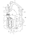
- FIG. 1 is a plan view showing an internal combustion engine 1 for an automobile provided with a blowby gas processing apparatus according to the present invention, including an intake system.
- the internal combustion engine 1 is mounted in the engine room at the front of the vehicle in a so-called horizontal orientation (the crankshaft center axis extends in the vehicle width direction), and the exhaust manifold 2 is in front of the vehicle (symbol FR in the figure).
- the intake manifold 3 is located on the rear side of the vehicle.
- a collector portion 3a forming a part of the intake manifold 3 is disposed on the vehicle rear side of the cylinder head cover 4 so as to be adjacent to the cylinder head cover 4.
- the throttle chamber 5 is disposed at an inlet portion at one longitudinal end of the collector portion 3a. Is connected.
- the throttle chamber 5 is internally provided with a throttle valve (not shown).
- An intake duct 6 made of a flexible material such as rubber or synthetic resin is connected to the upstream end of the throttle chamber 5, and the other end of the intake duct 6 is a cylindrical outlet of the air cleaner case 7. It is connected to the pipe 7a.
- An outside air introduction duct 8 made of a relatively hard synthetic resin material is connected to the inlet side of the air cleaner case 7, and a tip opening 8a of the outside air introduction duct 8 is open toward the front of the vehicle.
- An air cleaner element (not shown) is accommodated in the air cleaner case 7 so as to separate a so-called dust side to which the outside air introduction duct 8 is connected and a so-called clean side to which the air intake duct 6 is connected.
- the outlet pipe 7a of the air cleaner case 7 is provided with a hot-wire type air flow meter 11 for measuring the amount of intake air. That is, the air flow meter 11 is located upstream of the throttle valve.
- the resonator 12 has a substantially triangular or substantially L-shape elongated in the vehicle width direction in a plan view of the vehicle, and is disposed to overlap a part of the upper surface of the cylinder head cover 4.
- the resonator 12 has a simple hollow shape, and is divided into upper and lower parts into a lower body 13 and an upper body 14 which are each formed of an injection-molded product of hard synthetic resin. They are integrally joined to each other by vibration welding or the like. Then, as shown in FIG. 3, the resonator 12 has a neck portion 12 a at one end in the longitudinal direction adjacent to the intake duct 6, and the neck portion 12 a is connected to the branch pipe portion 6 a of the intake duct 6. It is done.
- the internal volume of the resonator 12 is in communication with the intake passage in the intake duct 6 (more specifically, between the throttle valve and the air flow meter 11) via the neck portion 12a, and the intake noise reduction operation is performed in a predetermined zone. can get.
- the neck portion 12 a is integrally formed with the lower body 13.
- the lower body 13 is integrally formed with a connector portion 15 for a fresh air introducing passage at a position relatively close to the neck portion 12a.
- the connector portion 15 is cylindrically protruded toward the inside of the substantially triangular or substantially L shape of the resonator 12 and, as shown in FIG. 2, extends along the flat bottom wall 13a of the lower body 13 . That is, in the vehicle mounted state, the connector portion 15 is provided at the lowermost position of the resonator 12.
- One end of a rubber-made fresh air introducing hose 16 which constitutes a part of a fresh air introducing passage is connected to the connector portion 15.
- the fresh air introducing hose 16 extends downward in a substantially L-shape, and the other end is connected to the connector portion 17 on the upper surface of the cylinder head cover 4 as shown in FIG.
- An oil separator 18 for a fresh air introducing passage is formed inside the cylinder head cover 4, and the fresh air introducing passage communicates with the inside of the crankcase (not shown) via the oil separator 18.
- one end of a rubber blow-by gas hose 20 constituting a part of the blow-by gas passage is connected to the upper surface of the cylinder head cover 4 and the other end of the blow-by gas hose 20 is not shown. It is connected to the collector portion 3 a of the intake manifold 3 via the PCV valve.
- An oil separator (not shown) is formed inside the cylinder head cover 4 for the blowby gas hose 20, and the blowby gas passage communicates with the inside of the crankcase (not shown) via the oil separator. There is.
- an orifice 21 for pressure pulsation reduction is integrally formed in the connector portion 15 of the resonator 12.
- the orifice 21 is composed of a partition wall 21a along the inner wall surface of the lower body 13 and an orifice hole 21b formed in the partition wall 21a.
- the connector portion 15 is formed simultaneously with the slide core.
- the partition wall 21a is along an arc surface that smoothly connects the bottom wall 13a and the side wall 13b of the lower body 13 and is located below the cylindrical connector portion 15 and is smaller than the inner diameter of the connector portion 15
- the small orifice hole 21b is open.
- the lowermost edge of the orifice hole 21 b substantially coincides with the bottom wall surface of the lower body 14.
- the orifice hole 21b is a non-circular hole (specifically, the outer edge forms an inverted U shape) when viewed from the axial direction of the connector portion 15 for convenience of molding. Of course, it may be a circular hole. In one embodiment, the inner diameter of the connector portion 15 is 12 mm, while the orifice hole 21 b has an equivalent diameter of about 7 mm. It is also possible to secondarily machine the orifice hole 21b after molding the partition wall 21a with a synthetic resin material.
- the blowby gas processing apparatus is configured mainly by the new air introduction passage formed by the fresh air introduction hose 16 and the blowby gas passage formed by the blowby gas hose 20. That is, in a low and medium load region where a sufficient pressure difference occurs before and after the throttle valve, fresh air is introduced from the throttle valve upstream side into the crankcase of the internal combustion engine 1 via the resonator 12. The blowby gas in the crankcase is introduced to the collector portion 3a through the blowby gas passage together with the introduced fresh air. The blow-by gas amount at this time is appropriately adjusted by a PCV valve (not shown). Further, in the high-speed high-load area where the pressure difference before and after the throttle valve is small and the blow-by gas generation amount is large, the blow-by gas mainly flows back through the new air introduction passage and is led upstream of the throttle valve.
- the fresh air introduction passage always communicates the crankcase and the throttle valve upstream side of the intake passage, the periodic pressure change in the crankcase, that is, the pressure pulsation of the blowby gas, is transmitted through the fresh air introduction passage to the intake passage.
- the orifice 21 is provided in the connector portion 15 which is a part of the fresh air introduction passage, so the pressure pulsation transmitted to the intake passage side is reduced by the throttling action.
- the orifice 21 is located immediately in front of the large volume of the resonator 12 and the gas passing through the orifice hole 21b is rapidly expanded, the pressure pulsation is more effectively reduced by the expansion action.
- the opening area of the orifice hole 21b is excessively large, the pulsation reducing effect can not be obtained, but if excessively small, the progress of oil deterioration due to blow-by gas in the crankcase is accelerated, so it is necessary to set appropriately.
- the orifice 21 is configured as a part of the resonator 12 which is usually designed for each vehicle type separately from the internal combustion engine 1 itself, tuning for each vehicle type is facilitated.
- the orifice 21 is formed integrally with the resonator 12 formed of a synthetic resin, pulsation can be reduced without an increase in the number of parts and a substantial increase in cost.
- the above-described resonator 12 also functions as a volume chamber (so-called catch tank) for oil recovery which separates and recovers oil mist entrained in blowby gas, in addition to the suction noise reduction action. That is, as described above, the blowby gas flowing back through the fresh air introduction passage at high speed and high load contains oil mist in the crankcase, but as a result, the flow velocity of the blowby gas in the resonator 12 decreases. Are separated and collected as droplets in the resonator 12. Then, the oil collected at the bottom of the resonator 12 flows through the fresh air introducing hose 16 to the cylinder head cover 4 side and finally returns to the inside of the crankcase.
- catch tank volume chamber
- the connector portion 15 of the fresh air introducing hose 16 is connected to the bottom portion of the resonator 12, and the connector portion is positioned so that the orifice hole 21b is at substantially the same height as the bottom wall surface of the lower body 13.
- the oil collected in the resonator 12 flows smoothly through the orifice hole 21b because it is formed offset to the lower side of the reference numeral 15. That is, the provision of the orifice 21 has no adverse effect on the recovery of oil.
Landscapes
- Engineering & Computer Science (AREA)
- Mechanical Engineering (AREA)
- General Engineering & Computer Science (AREA)
- Chemical & Material Sciences (AREA)
- Combustion & Propulsion (AREA)
- Lubrication Details And Ventilation Of Internal Combustion Engines (AREA)
Abstract
Description
As mentioned above, although one Example of this invention was described, this invention is not limited to the said Example, A various change is possible. For example, in the above embodiment, although both the fresh air introduction passage and the blow-by gas passage are connected to the
Claims (5)
- 吸気通路のスロットル弁上流側からクランクケース内へ至る新気導入通路と、クランクケース内から吸気通路のスロットル弁下流側へ至るブローバイガス通路と、を備えた内燃機関のブローバイガス処理装置において、
上記吸気通路の上記スロットル弁と上流側のエアフロメータとの間に、レゾネータが接続されているとともに、上記新気導入通路の一端が上記レゾネータに接続されており、この新気導入通路のレゾネータとの接続部にオリフィスが設けられている、内燃機関のブローバイガス処理装置。 A blowby gas processing system for an internal combustion engine, comprising: a fresh air introduction passage extending from the throttle valve upstream side of the intake passage to the inside of the crankcase; and a blowby gas passage extending from inside the crankcase to the throttle valve downstream side of the intake passage.
A resonator is connected between the throttle valve of the intake passage and the upstream air flow meter, and one end of the fresh air introduction passage is connected to the resonator, and a resonator of the fresh air introduction passage An internal combustion engine blow-by gas processing apparatus, wherein an orifice is provided at a connection portion of - 上記レゾネータは、上記新気導入通路となる配管が接続されるコネクタ部を有し、このコネクタ部に上記オリフィスが設けられている、請求項1に記載の内燃機関のブローバイガス処理装置。 The blowby gas processing apparatus for an internal combustion engine according to claim 1, wherein the resonator has a connector portion to which a pipe serving as the fresh air introduction passage is connected, and the connector portion is provided with the orifice.
- 上記レゾネータが合成樹脂成形品からなり、上記コネクタ部が上記レゾネータの一部として成形されているとともに、このコネクタ部と一体に上記オリフィスが形成されている、請求項2に記載の内燃機関のブローバイガス処理装置。 The blow-by of an internal combustion engine according to claim 2, wherein the resonator is made of a synthetic resin molded product, and the connector portion is formed as a part of the resonator, and the orifice is formed integrally with the connector portion. Gas processing equipment.
- 上記レゾネータは、ブローバイガスから分離したオイルを上記新気導入通路を通してクランクケース側へ戻すように、車両搭載姿勢で下側となる位置に上記コネクタ部が設けられている、請求項2または3に記載の内燃機関のブローバイガス処理装置。 4. The connector according to claim 2, wherein the resonator is provided at a lower position in a vehicle mounting posture so as to return the oil separated from the blowby gas to the crankcase through the fresh air introduction passage. Blow-by gas processing system for an internal combustion engine as described above.
- 円筒形をなす上記コネクタ部の下側に片寄って上記オリフィスが開口している、請求項4に記載の内燃機関のブローバイガス処理装置。 5. The blow-by gas processing system for an internal combustion engine according to claim 4, wherein the orifice is opened to the lower side of the cylindrical connector portion.
Priority Applications (4)
| Application Number | Priority Date | Filing Date | Title |
|---|---|---|---|
| JP2015529437A JP5967310B2 (en) | 2013-07-31 | 2014-06-10 | Blow-by gas processing device for internal combustion engine |
| CN201480053003.XA CN105612318B (en) | 2013-07-31 | 2014-06-10 | The blow-by gas processing device of internal combustion engine |
| EP14832209.2A EP3029288B1 (en) | 2013-07-31 | 2014-06-10 | Blow-by gas treatment device for internal combustion engine |
| US14/903,432 US9605624B2 (en) | 2013-07-31 | 2014-06-10 | Blow-by gas treatment device for internal combustion engine |
Applications Claiming Priority (2)
| Application Number | Priority Date | Filing Date | Title |
|---|---|---|---|
| JP2013-158382 | 2013-07-31 | ||
| JP2013158382 | 2013-07-31 |
Publications (1)
| Publication Number | Publication Date |
|---|---|
| WO2015015907A1 true WO2015015907A1 (en) | 2015-02-05 |
Family
ID=52431451
Family Applications (1)
| Application Number | Title | Priority Date | Filing Date |
|---|---|---|---|
| PCT/JP2014/065292 WO2015015907A1 (en) | 2013-07-31 | 2014-06-10 | Blow-by gas treatment device for internal combustion engine |
Country Status (5)
| Country | Link |
|---|---|
| US (1) | US9605624B2 (en) |
| EP (1) | EP3029288B1 (en) |
| JP (1) | JP5967310B2 (en) |
| CN (1) | CN105612318B (en) |
| WO (1) | WO2015015907A1 (en) |
Cited By (2)
| Publication number | Priority date | Publication date | Assignee | Title |
|---|---|---|---|---|
| JP2017150418A (en) * | 2016-02-25 | 2017-08-31 | トヨタ紡織株式会社 | Blow-by gas hose connection structure |
| JP2018162669A (en) * | 2017-03-24 | 2018-10-18 | マツダ株式会社 | Ventilation device for engine |
Families Citing this family (2)
| Publication number | Priority date | Publication date | Assignee | Title |
|---|---|---|---|---|
| JP6969964B2 (en) * | 2017-10-12 | 2021-11-24 | トヨタ自動車株式会社 | Piping part connection structure |
| CN113482812B (en) * | 2021-06-30 | 2022-11-01 | 东风汽车集团股份有限公司 | Anti-icing device for air inlet main pipeline and vehicle |
Citations (9)
| Publication number | Priority date | Publication date | Assignee | Title |
|---|---|---|---|---|
| JPS6412051A (en) * | 1987-07-02 | 1989-01-17 | Mazda Motor | Fuel injection device for multicylinder engine |
| JPH07301165A (en) * | 1994-05-02 | 1995-11-14 | Nissan Motor Co Ltd | Air intake duct device for internal combustion engine |
| JP2006250080A (en) * | 2005-03-11 | 2006-09-21 | Toyota Motor Corp | Internal combustion engine with blowby gas treatment device |
| JP2009257117A (en) * | 2008-04-14 | 2009-11-05 | Denso Corp | Abnormality diagnosis device for intake system of internal combustion engine |
| JP2010096028A (en) | 2008-10-14 | 2010-04-30 | Toyota Motor Corp | Crankcase emission control system for internal combustion engine |
| JP2012021491A (en) * | 2010-07-16 | 2012-02-02 | Honda Motor Co Ltd | Internal combustion engine |
| JP2012241561A (en) * | 2011-05-17 | 2012-12-10 | Nifco Inc | Resonator |
| JP2013107599A (en) * | 2011-11-24 | 2013-06-06 | Nippon Plast Co Ltd | Resonator |
| JP2013113109A (en) | 2011-11-25 | 2013-06-10 | Honda Motor Co Ltd | Head cover structure for internal combustion engine |
Family Cites Families (9)
| Publication number | Priority date | Publication date | Assignee | Title |
|---|---|---|---|---|
| JP2663072B2 (en) * | 1991-12-27 | 1997-10-15 | 株式会社ユニシアジェックス | Apparatus for detecting fuel concentration in blow-by gas |
| JP3942444B2 (en) * | 2002-01-22 | 2007-07-11 | 株式会社日本自動車部品総合研究所 | Evaporative fuel processing equipment |
| JP4321606B2 (en) * | 2007-02-28 | 2009-08-26 | トヨタ自動車株式会社 | Blow-by gas reduction device, cylinder head used in the blow-by gas reduction device, and internal combustion engine including the blow-by gas reduction device |
| JP2008215152A (en) * | 2007-03-02 | 2008-09-18 | Mahle Filter Systems Japan Corp | Ventilation device for internal combustion engine |
| JP5125399B2 (en) * | 2007-10-19 | 2013-01-23 | 日産自動車株式会社 | Engine blow-by gas recovery system |
| US8118013B2 (en) * | 2008-09-24 | 2012-02-21 | GM Global Technology Operations LLC | Resonator and crankcase ventilation system for internal combustion engine |
| JP5006298B2 (en) * | 2008-10-10 | 2012-08-22 | 愛三工業株式会社 | Blow-by gas reduction device |
| JP2010168920A (en) * | 2009-01-20 | 2010-08-05 | Toyota Motor Corp | Internal combustion engine |
| US8967128B2 (en) * | 2013-06-03 | 2015-03-03 | Ford Global Technologies, Llc | Multiple layer bypass hydrocarbon trap |
-
2014
- 2014-06-10 EP EP14832209.2A patent/EP3029288B1/en active Active
- 2014-06-10 WO PCT/JP2014/065292 patent/WO2015015907A1/en active Application Filing
- 2014-06-10 US US14/903,432 patent/US9605624B2/en active Active
- 2014-06-10 JP JP2015529437A patent/JP5967310B2/en active Active
- 2014-06-10 CN CN201480053003.XA patent/CN105612318B/en active Active
Patent Citations (9)
| Publication number | Priority date | Publication date | Assignee | Title |
|---|---|---|---|---|
| JPS6412051A (en) * | 1987-07-02 | 1989-01-17 | Mazda Motor | Fuel injection device for multicylinder engine |
| JPH07301165A (en) * | 1994-05-02 | 1995-11-14 | Nissan Motor Co Ltd | Air intake duct device for internal combustion engine |
| JP2006250080A (en) * | 2005-03-11 | 2006-09-21 | Toyota Motor Corp | Internal combustion engine with blowby gas treatment device |
| JP2009257117A (en) * | 2008-04-14 | 2009-11-05 | Denso Corp | Abnormality diagnosis device for intake system of internal combustion engine |
| JP2010096028A (en) | 2008-10-14 | 2010-04-30 | Toyota Motor Corp | Crankcase emission control system for internal combustion engine |
| JP2012021491A (en) * | 2010-07-16 | 2012-02-02 | Honda Motor Co Ltd | Internal combustion engine |
| JP2012241561A (en) * | 2011-05-17 | 2012-12-10 | Nifco Inc | Resonator |
| JP2013107599A (en) * | 2011-11-24 | 2013-06-06 | Nippon Plast Co Ltd | Resonator |
| JP2013113109A (en) | 2011-11-25 | 2013-06-10 | Honda Motor Co Ltd | Head cover structure for internal combustion engine |
Cited By (2)
| Publication number | Priority date | Publication date | Assignee | Title |
|---|---|---|---|---|
| JP2017150418A (en) * | 2016-02-25 | 2017-08-31 | トヨタ紡織株式会社 | Blow-by gas hose connection structure |
| JP2018162669A (en) * | 2017-03-24 | 2018-10-18 | マツダ株式会社 | Ventilation device for engine |
Also Published As
| Publication number | Publication date |
|---|---|
| EP3029288B1 (en) | 2017-08-23 |
| US9605624B2 (en) | 2017-03-28 |
| EP3029288A4 (en) | 2016-10-05 |
| US20160160802A1 (en) | 2016-06-09 |
| CN105612318B (en) | 2018-05-04 |
| CN105612318A (en) | 2016-05-25 |
| JP5967310B2 (en) | 2016-08-10 |
| EP3029288A1 (en) | 2016-06-08 |
| JPWO2015015907A1 (en) | 2017-03-02 |
Similar Documents
| Publication | Publication Date | Title |
|---|---|---|
| JP5626597B2 (en) | Intake manifold | |
| WO2015015907A1 (en) | Blow-by gas treatment device for internal combustion engine | |
| US20060027202A1 (en) | Air intake device for two-wheeled motor vehicle | |
| JP5290732B2 (en) | Oil separator for internal combustion engine | |
| US20150337698A1 (en) | Separation device for an aerosol stream | |
| CN104428502A (en) | Blowby gas ventilation system for supercharger-equipped internal combustion engine | |
| JP2009121281A (en) | Oil separator for internal combustion engine | |
| JP5978751B2 (en) | Blowby gas recirculation structure | |
| CN110107376B (en) | Blow-by gas treatment device for internal combustion engine | |
| CN105971783A (en) | Vehicular suction noise transmission device | |
| JP2009047141A (en) | Oil separation device for engine | |
| JP5686692B2 (en) | Resin intake manifold | |
| JP2017180261A (en) | Surge tank integrated intake manifold | |
| JP2013249822A (en) | Intake manifold | |
| US9212637B2 (en) | Intake pipe structure for internal combustion engine | |
| JP4357233B2 (en) | Internal combustion engine surge tank | |
| JP5959517B2 (en) | Intake device | |
| JP6933700B2 (en) | Head cover structure | |
| JP6289043B2 (en) | Resonator | |
| JP6025582B2 (en) | Intake manifold | |
| JP4192551B2 (en) | Oil separator | |
| JP2014181624A (en) | Intake device of internal combustion engine | |
| EP3653864B1 (en) | Structure for suctioning back blow-back fuel | |
| JP2021127700A (en) | Oil separation structure | |
| JP2003056325A (en) | Oil separation structure of blow-by gas disposing fresh air passage |
Legal Events
| Date | Code | Title | Description |
|---|---|---|---|
| 121 | Ep: the epo has been informed by wipo that ep was designated in this application |
Ref document number: 14832209 Country of ref document: EP Kind code of ref document: A1 |
|
| ENP | Entry into the national phase |
Ref document number: 2015529437 Country of ref document: JP Kind code of ref document: A |
|
| WWE | Wipo information: entry into national phase |
Ref document number: 14903432 Country of ref document: US |
|
| NENP | Non-entry into the national phase |
Ref country code: DE |
|
| REEP | Request for entry into the european phase |
Ref document number: 2014832209 Country of ref document: EP |
|
| WWE | Wipo information: entry into national phase |
Ref document number: 2014832209 Country of ref document: EP |