EP3029288A1 - Blow-by gas treatment device for internal combustion engine - Google Patents
Blow-by gas treatment device for internal combustion engine Download PDFInfo
- Publication number
- EP3029288A1 EP3029288A1 EP14832209.2A EP14832209A EP3029288A1 EP 3029288 A1 EP3029288 A1 EP 3029288A1 EP 14832209 A EP14832209 A EP 14832209A EP 3029288 A1 EP3029288 A1 EP 3029288A1
- Authority
- EP
- European Patent Office
- Prior art keywords
- blow
- resonator
- fresh air
- air introduction
- passage
- Prior art date
- Legal status (The legal status is an assumption and is not a legal conclusion. Google has not performed a legal analysis and makes no representation as to the accuracy of the status listed.)
- Granted
Links
- 238000002485 combustion reaction Methods 0.000 title claims description 19
- 229920003002 synthetic resin Polymers 0.000 claims abstract description 7
- 239000000057 synthetic resin Substances 0.000 claims abstract description 7
- 238000011144 upstream manufacturing Methods 0.000 claims description 17
- 230000010349 pulsation Effects 0.000 abstract description 12
- 230000000694 effects Effects 0.000 abstract description 8
- 238000005192 partition Methods 0.000 description 4
- 239000000463 material Substances 0.000 description 3
- 239000003595 mist Substances 0.000 description 3
- 230000008859 change Effects 0.000 description 2
- 238000010276 construction Methods 0.000 description 2
- 230000009467 reduction Effects 0.000 description 2
- 230000009471 action Effects 0.000 description 1
- 230000002411 adverse Effects 0.000 description 1
- 230000003247 decreasing effect Effects 0.000 description 1
- 230000006866 deterioration Effects 0.000 description 1
- 239000000428 dust Substances 0.000 description 1
- 230000006872 improvement Effects 0.000 description 1
- 238000002347 injection Methods 0.000 description 1
- 239000007924 injection Substances 0.000 description 1
- 238000003754 machining Methods 0.000 description 1
- 230000004048 modification Effects 0.000 description 1
- 238000012986 modification Methods 0.000 description 1
- 230000001902 propagating effect Effects 0.000 description 1
- 238000011084 recovery Methods 0.000 description 1
- 238000007493 shaping process Methods 0.000 description 1
- 238000003466 welding Methods 0.000 description 1
Images


Classifications
-
- F—MECHANICAL ENGINEERING; LIGHTING; HEATING; WEAPONS; BLASTING
- F02—COMBUSTION ENGINES; HOT-GAS OR COMBUSTION-PRODUCT ENGINE PLANTS
- F02M—SUPPLYING COMBUSTION ENGINES IN GENERAL WITH COMBUSTIBLE MIXTURES OR CONSTITUENTS THEREOF
- F02M25/00—Engine-pertinent apparatus for adding non-fuel substances or small quantities of secondary fuel to combustion-air, main fuel or fuel-air mixture
- F02M25/06—Engine-pertinent apparatus for adding non-fuel substances or small quantities of secondary fuel to combustion-air, main fuel or fuel-air mixture adding lubricant vapours
-
- F—MECHANICAL ENGINEERING; LIGHTING; HEATING; WEAPONS; BLASTING
- F01—MACHINES OR ENGINES IN GENERAL; ENGINE PLANTS IN GENERAL; STEAM ENGINES
- F01M—LUBRICATING OF MACHINES OR ENGINES IN GENERAL; LUBRICATING INTERNAL COMBUSTION ENGINES; CRANKCASE VENTILATING
- F01M11/00—Component parts, details or accessories, not provided for in, or of interest apart from, groups F01M1/00 - F01M9/00
- F01M11/08—Separating lubricant from air or fuel-air mixture before entry into cylinder
-
- F—MECHANICAL ENGINEERING; LIGHTING; HEATING; WEAPONS; BLASTING
- F01—MACHINES OR ENGINES IN GENERAL; ENGINE PLANTS IN GENERAL; STEAM ENGINES
- F01M—LUBRICATING OF MACHINES OR ENGINES IN GENERAL; LUBRICATING INTERNAL COMBUSTION ENGINES; CRANKCASE VENTILATING
- F01M13/00—Crankcase ventilating or breathing
- F01M13/02—Crankcase ventilating or breathing by means of additional source of positive or negative pressure
- F01M13/021—Crankcase ventilating or breathing by means of additional source of positive or negative pressure of negative pressure
- F01M13/022—Crankcase ventilating or breathing by means of additional source of positive or negative pressure of negative pressure using engine inlet suction
-
- F—MECHANICAL ENGINEERING; LIGHTING; HEATING; WEAPONS; BLASTING
- F01—MACHINES OR ENGINES IN GENERAL; ENGINE PLANTS IN GENERAL; STEAM ENGINES
- F01M—LUBRICATING OF MACHINES OR ENGINES IN GENERAL; LUBRICATING INTERNAL COMBUSTION ENGINES; CRANKCASE VENTILATING
- F01M13/00—Crankcase ventilating or breathing
- F01M13/02—Crankcase ventilating or breathing by means of additional source of positive or negative pressure
- F01M13/028—Crankcase ventilating or breathing by means of additional source of positive or negative pressure of positive pressure
-
- F—MECHANICAL ENGINEERING; LIGHTING; HEATING; WEAPONS; BLASTING
- F01—MACHINES OR ENGINES IN GENERAL; ENGINE PLANTS IN GENERAL; STEAM ENGINES
- F01M—LUBRICATING OF MACHINES OR ENGINES IN GENERAL; LUBRICATING INTERNAL COMBUSTION ENGINES; CRANKCASE VENTILATING
- F01M13/00—Crankcase ventilating or breathing
- F01M13/04—Crankcase ventilating or breathing having means for purifying air before leaving crankcase, e.g. removing oil
- F01M13/0416—Crankcase ventilating or breathing having means for purifying air before leaving crankcase, e.g. removing oil arranged in valve-covers
-
- F—MECHANICAL ENGINEERING; LIGHTING; HEATING; WEAPONS; BLASTING
- F02—COMBUSTION ENGINES; HOT-GAS OR COMBUSTION-PRODUCT ENGINE PLANTS
- F02M—SUPPLYING COMBUSTION ENGINES IN GENERAL WITH COMBUSTIBLE MIXTURES OR CONSTITUENTS THEREOF
- F02M35/00—Combustion-air cleaners, air intakes, intake silencers, or induction systems specially adapted for, or arranged on, internal-combustion engines
- F02M35/10—Air intakes; Induction systems
- F02M35/10209—Fluid connections to the air intake system; their arrangement of pipes, valves or the like
- F02M35/10222—Exhaust gas recirculation [EGR]; Positive crankcase ventilation [PCV]; Additional air admission, lubricant or fuel vapour admission
-
- F—MECHANICAL ENGINEERING; LIGHTING; HEATING; WEAPONS; BLASTING
- F02—COMBUSTION ENGINES; HOT-GAS OR COMBUSTION-PRODUCT ENGINE PLANTS
- F02M—SUPPLYING COMBUSTION ENGINES IN GENERAL WITH COMBUSTIBLE MIXTURES OR CONSTITUENTS THEREOF
- F02M35/00—Combustion-air cleaners, air intakes, intake silencers, or induction systems specially adapted for, or arranged on, internal-combustion engines
- F02M35/12—Intake silencers ; Sound modulation, transmission or amplification
- F02M35/1255—Intake silencers ; Sound modulation, transmission or amplification using resonance
- F02M35/1261—Helmholtz resonators
-
- F—MECHANICAL ENGINEERING; LIGHTING; HEATING; WEAPONS; BLASTING
- F02—COMBUSTION ENGINES; HOT-GAS OR COMBUSTION-PRODUCT ENGINE PLANTS
- F02M—SUPPLYING COMBUSTION ENGINES IN GENERAL WITH COMBUSTIBLE MIXTURES OR CONSTITUENTS THEREOF
- F02M35/00—Combustion-air cleaners, air intakes, intake silencers, or induction systems specially adapted for, or arranged on, internal-combustion engines
- F02M35/12—Intake silencers ; Sound modulation, transmission or amplification
- F02M35/1288—Intake silencers ; Sound modulation, transmission or amplification combined with or integrated into other devices ; Plurality of air intake silencers
-
- F—MECHANICAL ENGINEERING; LIGHTING; HEATING; WEAPONS; BLASTING
- F01—MACHINES OR ENGINES IN GENERAL; ENGINE PLANTS IN GENERAL; STEAM ENGINES
- F01M—LUBRICATING OF MACHINES OR ENGINES IN GENERAL; LUBRICATING INTERNAL COMBUSTION ENGINES; CRANKCASE VENTILATING
- F01M13/00—Crankcase ventilating or breathing
- F01M13/04—Crankcase ventilating or breathing having means for purifying air before leaving crankcase, e.g. removing oil
- F01M2013/0488—Crankcase ventilating or breathing having means for purifying air before leaving crankcase, e.g. removing oil with oil trap in the return conduit to the crankcase
-
- Y—GENERAL TAGGING OF NEW TECHNOLOGICAL DEVELOPMENTS; GENERAL TAGGING OF CROSS-SECTIONAL TECHNOLOGIES SPANNING OVER SEVERAL SECTIONS OF THE IPC; TECHNICAL SUBJECTS COVERED BY FORMER USPC CROSS-REFERENCE ART COLLECTIONS [XRACs] AND DIGESTS
- Y02—TECHNOLOGIES OR APPLICATIONS FOR MITIGATION OR ADAPTATION AGAINST CLIMATE CHANGE
- Y02T—CLIMATE CHANGE MITIGATION TECHNOLOGIES RELATED TO TRANSPORTATION
- Y02T10/00—Road transport of goods or passengers
- Y02T10/10—Internal combustion engine [ICE] based vehicles
- Y02T10/12—Improving ICE efficiencies
Definitions
- the present invention relates to an improvement of a blow-by gas treatment device for an internal combustion engine, the device being so adapted that brow-by gas in a crankcase of an internal combustion engine is led into an air intake system and then burned in a combustion chamber.
- Patent Document 1 there is disclosed a brow-by gas treatment device for an internal combustion engine, the device comprising a fresh air introduction passage for introducing a fresh air into a crankcase from the upstream side (with respect to a throttle valve) of an intake air passage and a blow-by gas passage for emitting blow-by gas from the crankcase into the downstream side (with respect to the throttle valve) of the intake air passage.
- a fresh air introduction passage for introducing a fresh air into a crankcase from the upstream side (with respect to a throttle valve) of an intake air passage and a blow-by gas passage for emitting blow-by gas from the crankcase into the downstream side (with respect to the throttle valve) of the intake air passage.
- One end of the fresh air introduction passage is connected to between the throttle valve of the intake air passage and an air flow meter disposed upstream therefrom.
- a fresh air is introduced into the crankcase by a difference in pressure between upstream and downstream from the throttle valve while a blow-by gas is introduced toward the downstream side of the throttle valve together with this fresh air, and finally a combustion treatment is initiated in a combustion chamber.
- the blow-by gas flows backwardly through the fresh air introduction passage to be introduced to the upstream side of the throttle valve.
- Patent Document 2 discloses an arrangement where an oil separator for the fresh air introduction passage and an oil separator for the blow-by gas passage are provided inside a cylinder head cover of an internal combustion engine and the tip end of the fresh air introduction passage and that of the blow-by gas passage are respectively connected thereto.
- An aspect of the present invention resides in a blow-by gas treatment device for internal combustion engine which device is equipped with a fresh air introduction passage leading from the upstream side of a throttle valve of an intake air passage to an interior of a crankcase and a blow-by gas passage leading from the interior of the crankcase to the downstream side of the throttle valve of the intake air passage, wherein a resonator is connected to between the throttle valve of the intake air passage and an air flow meter disposed on the upstream side therefrom while one end of the fresh air introduction passage is connected to the resonator, and there is provided an orifice at a connected section of the fresh air introduction passage and the resonator.
- the resonator is connected to the intake air passage, as the so-called Helmholtz type resonator element, to contribute to a reduction of intake air noise.
- the fresh air introduction passage is arranged to communicate with the intake air passage through the resonator, so that a fresh air is to flow from the intake air passage through the resonator into the fresh air introduction passage. Meanwhile, at the time when blow-by gas flows backwardly in a high load region, the blow-by gas is to flow from the fresh air introduction passage through the resonator into the intake air passage.
- an orifice is provided at the fresh air introduction passage or at a connected section disposed between of the fresh air introduction passage and the resonator, thereby producing a throttling effect.
- a pressure pulsation which tends to propagate from the crankcase side to the intake air passage side is reduced.
- the orifice is provided at a location immediately before the resonator where the volume is increased and therefore a gas throttled at the orifice is expanded abruptly at the resonator, a pressure pulsation is more effectively reduced by such an expansion effect.
- the present invention it is possible to suppress a pressure pulsation which tends to propagate through the fresh air introduction passage to the upstream side of the intake air passage with respect to the throttle valve, thereby reducing an error of the air flow meter in measuring the amount of intake air.
- Fig. 1 is a plan view showing an automotive internal combustion engine 1 equipped with a brow-by gas treatment device according to the present invention, including an air intake system.
- the internal combustion engine 1 is mounted in an engine compartment disposed on the front side of a vehicle, in the so-called transverse posture (or an arrangement bringing the center axis of a crank shaft into line with the vehicle width direction).
- An exhaust manifold 2 is located on the front side of the vehicle (indicated in the drawing by "FR") while an intake manifold 3 is located on the rear side of the vehicle.
- a collector portion 3a serving as a part of the intake manifold 3 is disposed adjacent to a cylinder head cover 4 on the rear side of the vehicle from the cylinder head cover 4.
- the collector portion 3a has an inlet portion at one longitudinal end, to which a throttle chamber 5 is connected.
- the throttle chamber 5 is provided having a throttle valve in its interior (though not shown).
- an intake air duct 6 formed of a flexible material such as rubber, synthetic resin and the like is connected, while the other end of the intake air duct 6 is connected to a cylindrical-shaped outlet pipe 7a of an air cleaner case 7.
- An inlet side of the air cleaner case 7 is connected to an outside-air introduction duct 8 formed of a relatively hard synthetic resin material.
- the outside-air introduction duct 8 is formed to open toward the front of the vehicle, at tip end opening 8a.
- an air cleaner element is housed to divide the so-called dust side on which the outside-air introduction duct is connected and the so-called clean side on which the intake air duct 6 is connected from each other, though not shown.
- a heat wire air flow meter 11 for measuring the amount of intake air is attached to the outlet pipe 7a.
- the air flow meter 11 is located on the upstream side from the throttle valve.
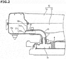
- a resonator 12 constituting a Helmholtz type resonance chamber for reducing intake air noise is disposed above the cylinder head cover 4.
- the resonator 12 roughly has a shape of a triangle or a letter L slenderly extending in the vehicle width direction in a plan view of the vehicle, and located overlapping the top surface of the cylinder head cover 4.
- the resonator 12 has a simple hollow shape which can vertically be divided into a lower body 13 and an upper body 14, each of which comprises an injection molded article of a hard synthetic resin and joined integral with each other by vibration welding or the like. Additionally, the resonator 12 is provided with a neck tube part 12a at one longitudinal end portion adjacent to the intake air duct 6 as shown in Fig. 3 , and the neck tube part 12a is connected to a branch pipe section 6a of the intake air duct 6.
- the internal content of the resonator 12 is arranged to communicate with an intake air passage defined inside the intake air duct 6 (more specifically, between the throttle valve and the air flow meter 11) through the neck tube part 12a, so that the effect of reducing intake air noise is obtained within a certain band.
- the neck tube part 12a is formed integral with the lower body 13.
- the lower body 13 is further formed integral with a connector part 15 for a fresh air introduction passage at a position relatively close to the neck tube part 12a, as shown in Figs. 2 to 4 .
- the connector part 15 is so formed as to cylindrically protrude toward the inside of the triangular or L-like shape of the resonator 12 and extend along a flat bottom wall 13a of the lower body 13 as shown in Fig. 2 .
- the connector part 15 is provided at the lowermost position of the resonator 12 in a vehicle-mounted state.
- a fresh air introduction hose 16 formed of rubber and constituting a part of the fresh air introduction passage is connected to the connector part 15.
- the fresh air introduction hose 16 is provided extending downward to be shaped generally into a letter L, and connected at its other end to a connector section 17 provided to the top surface of the cylinder head cover 4 as shown in Fig. 2 .
- the fresh air introduction passage is arranged to communicate with the interior of a crankcase through the oil separator 18 (though not shown).
- blow-by gas hose 20 formed of rubber and constituting a part of a blow-by gas passage is also connected.
- the other end of the blow-by gas hose 20 is connected to the collector portion 3a of the intake manifold 3 through a PCV valve (though not shown).
- a further oil separator inside the cylinder head cover 4 (though not shown).
- the blow-by gas passage is arranged to communicate with the interior of the crankcase through this not-illustrated oil separator.
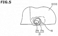
- the resonator 12 is formed integral with an orifice 21 for reducing a pressure pulsation, at the connector part 15. More specifically, as shown in Figs. 2 and 5 , the orifice 21 is provided including a partition wall 21a extending along an inner wall surface of the lower body 13 and an orifice hole 21b formed opening at the partition wall 21a, and formed at the same time of forming the cylindrical connector part 15 by a slide core.
- the partition wall 21a extends along an arcuate plane that smoothly links the bottom wall 13a and a side wall 13b of the lower body 13 so that the orifice hole 21b is defined opening at a downwardly biased position of the cylindrical-shaped connector part 15, the orifice hole 21b having a diameter smaller than the inner diameter of the connector part 15.
- the lowermost edge of the orifice hole 21b is substantially coincident with the surface of the bottom wall of the lower body 14.
- the orifice hole 21b in the present embodiment is a noncircular hole when viewed in the axial direction of the connector part 15 (to be more specific, a hole the outer edge of which is formed to have an inversed U-shape) for convenience in shaping, it will be understood that a perfectly circular hole is also acceptable.
- the connector part 15 has an inner diameter of 12 mm while the orifice hole 21b has an equivalent diameter of about 7 mm.
- the brow-by gas treatment device is constituted mainly of: the fresh air introduction passage comprising the fresh air introduction hose 16; and the brow-by gas passage comprising the blow-by gas hose 20.
- a fresh air is introduced from the upstream side of the throttle valve into the crankcase of the internal combustion engine 1 by way of the resonator 12.
- a blow-by gas that resides in the crankcase is introduced into the collector portion 3a through the blow-by gas passage, together with the thus introduced fresh air.
- the amount of blow-by gas is suitably adjusted by the not-illustrated PCV valve at this time.
- the blow-by gas mainly flows through the fresh air introduction passage backwardly to be introduced to the upstream side of the throttle valve.
- the fresh air introduction passage always communicates the crankcase with the intake air passage at the upstream side from the throttle valve and therefore a periodical change in pressure within the crankcase or a pressure pulsation of blow-by gas is apt to propagate to the intake air passage side through the fresh air introduction passage; however, in the above-mentioned construction, the connector part 15 serving as a part of the fresh air introduction passage is provided with the orifice 21, and the throttling effect thereof reduces the pressure pulsation propagating to the intake air passage side.
- the orifice 21 is provided at a location immediately before the large content of the resonator 12, with which gas having passed through the orifice hole 21b can abruptly expand. By the expansion effect, the pressure pulsation can more effectively be reduced.
- the opening are of the orifice hole 21b is required to suitably be determined because an excessively large one impairs the pulsation-reducing effect while an excessively small one accelerates the progress of oil deterioration due to blow-by gas that resides in the crankcase.
- the above-mentioned construction of the present embodiment is arranged to provide the orifice 21 as a part of the resonator 12 (designed according to each model in usual, separately from the internal combustion engine 1 itself), thereby facilitating tuning of each model.
- the orifice 21 is formed integral with the resonator 12 formed of a synthetic resin. It is therefore possible to promote the reduction of pulsation without increasing the number of components and without increasing an actual cost.
- the resonator 12 also functions as an oil-recovering volume chamber where oil mist having attended blow-by gas is separated and recovered (i.e., the so-called catch tank) in addition to the intake air noise-reducing action.
- blow-by gas which is to backwardly flow through the fresh air introduction passage in a high-speed high-load region as mentioned above contains oil mist that resides in the crankcase; as a result of the blow-by gas decreasing its flow velocity within the resonator 12, the oil mist is separated and recovered in the form of droplets into the resonator 12. Then, the oil collected at the bottom of the resonator 12 is to flow toward the cylinder head cover 4 through the fresh air introduction hose 16, and finally come back into the crankcase.
- the connector par 15 of the fresh air introduction hose 16 is connected to the bottom of the resonator 12 and the orifice hole 21b is defined opening at a downwardly biased position of the connector part 15 so as to have a height equal to the surface of the bottom wall of the lower body 13.
- oil collected within the resonator 12 can flow without a hitch through the orifice hole 21b.
- the provision of the orifice hole 21b never adversely affects the recovery of oil.
Abstract
Description
- The present invention relates to an improvement of a blow-by gas treatment device for an internal combustion engine, the device being so adapted that brow-by gas in a crankcase of an internal combustion engine is led into an air intake system and then burned in a combustion chamber.
- In Patent Document 1, there is disclosed a brow-by gas treatment device for an internal combustion engine, the device comprising a fresh air introduction passage for introducing a fresh air into a crankcase from the upstream side (with respect to a throttle valve) of an intake air passage and a blow-by gas passage for emitting blow-by gas from the crankcase into the downstream side (with respect to the throttle valve) of the intake air passage. One end of the fresh air introduction passage is connected to between the throttle valve of the intake air passage and an air flow meter disposed upstream therefrom.
- In the thus constructed blow-by gas treatment device, a fresh air is introduced into the crankcase by a difference in pressure between upstream and downstream from the throttle valve while a blow-by gas is introduced toward the downstream side of the throttle valve together with this fresh air, and finally a combustion treatment is initiated in a combustion chamber. In a high-speed high-load region where a difference in pressure between upstream and downstream from the throttle valve is small and the generated amount of blow-by gas is large, the blow-by gas flows backwardly through the fresh air introduction passage to be introduced to the upstream side of the throttle valve.
- With consideration given to the backflow of blow-by gas in the fresh air introduction passage,
Patent Document 2 discloses an arrangement where an oil separator for the fresh air introduction passage and an oil separator for the blow-by gas passage are provided inside a cylinder head cover of an internal combustion engine and the tip end of the fresh air introduction passage and that of the blow-by gas passage are respectively connected thereto. - In such an arrangement where the fresh air introduction passage is connected to between the throttle vale of the intake air passage and the air flow meter, a periodical change in pressure within the crankcase or a pressure pulsation of blow-by gas is apt to propagate to the intake air passage side through the fresh air introduction passage, which makes the air flow meter cause an error in measuring the amount of intake air. Particularly in the case of using a highly responsive air flow meter, an influence of pulsation of blow-by gas is outstandingly exhibited in a low load region (for example, in an idle state) where the amount of intake air is small.
-
- Patent Document 1: Japanese Patent Application Publication No.
2010-96028 - Patent Document 2: Japanese Patent Application Publication No.
2013-113109 - An aspect of the present invention resides in a blow-by gas treatment device for internal combustion engine which device is equipped with a fresh air introduction passage leading from the upstream side of a throttle valve of an intake air passage to an interior of a crankcase and a blow-by gas passage leading from the interior of the crankcase to the downstream side of the throttle valve of the intake air passage, wherein a resonator is connected to between the throttle valve of the intake air passage and an air flow meter disposed on the upstream side therefrom while one end of the fresh air introduction passage is connected to the resonator, and there is provided an orifice at a connected section of the fresh air introduction passage and the resonator.
- The resonator is connected to the intake air passage, as the so-called Helmholtz type resonator element, to contribute to a reduction of intake air noise. The fresh air introduction passage is arranged to communicate with the intake air passage through the resonator, so that a fresh air is to flow from the intake air passage through the resonator into the fresh air introduction passage. Meanwhile, at the time when blow-by gas flows backwardly in a high load region, the blow-by gas is to flow from the fresh air introduction passage through the resonator into the intake air passage.
- In the present invention, an orifice is provided at the fresh air introduction passage or at a connected section disposed between of the fresh air introduction passage and the resonator, thereby producing a throttling effect. With this, a pressure pulsation which tends to propagate from the crankcase side to the intake air passage side is reduced. In particular, since the orifice is provided at a location immediately before the resonator where the volume is increased and therefore a gas throttled at the orifice is expanded abruptly at the resonator, a pressure pulsation is more effectively reduced by such an expansion effect.
- According to the present invention, it is possible to suppress a pressure pulsation which tends to propagate through the fresh air introduction passage to the upstream side of the intake air passage with respect to the throttle valve, thereby reducing an error of the air flow meter in measuring the amount of intake air.
-
- [
Fig. 1 ] A plan view of the whole of an internal combustion engine equipped with a blow-by gas treatment device according to the present invention. - [
Fig. 2 ] A cross-sectional view showing a cross section of an essential part of a resonator. - [
Fig. 3 ] A perspective view showing an essential part. - [
Fig. 4 ] A perspective view showing a connected section of an intake air duct and the resonator. - [
Fig. 5 ] A front view of an essential part, showing a connector part of the resonator. - Referring now to the accompanying drawings, an embodiment of the present invention will be discussed in detail.
-
Fig. 1 is a plan view showing an automotive internal combustion engine 1 equipped with a brow-by gas treatment device according to the present invention, including an air intake system. The internal combustion engine 1 is mounted in an engine compartment disposed on the front side of a vehicle, in the so-called transverse posture (or an arrangement bringing the center axis of a crank shaft into line with the vehicle width direction). Anexhaust manifold 2 is located on the front side of the vehicle (indicated in the drawing by "FR") while anintake manifold 3 is located on the rear side of the vehicle. Acollector portion 3a serving as a part of theintake manifold 3 is disposed adjacent to a cylinder head cover 4 on the rear side of the vehicle from the cylinder head cover 4. Thecollector portion 3a has an inlet portion at one longitudinal end, to which athrottle chamber 5 is connected. Thethrottle chamber 5 is provided having a throttle valve in its interior (though not shown). - To an upstream end of the
throttle chamber 5 one end of anintake air duct 6 formed of a flexible material such as rubber, synthetic resin and the like is connected, while the other end of theintake air duct 6 is connected to a cylindrical-shaped outlet pipe 7a of an air cleaner case 7. An inlet side of the air cleaner case 7 is connected to an outside-air introduction duct 8 formed of a relatively hard synthetic resin material. The outside-air introduction duct 8 is formed to open toward the front of the vehicle, at tip end opening 8a. In the air cleaner case 7, an air cleaner element is housed to divide the so-called dust side on which the outside-air introduction duct is connected and the so-called clean side on which theintake air duct 6 is connected from each other, though not shown. - To the
outlet pipe 7a, a heat wireair flow meter 11 for measuring the amount of intake air is attached. In other words, theair flow meter 11 is located on the upstream side from the throttle valve. - Above the cylinder head cover 4, a
resonator 12 constituting a Helmholtz type resonance chamber for reducing intake air noise is disposed. Theresonator 12 roughly has a shape of a triangle or a letter L slenderly extending in the vehicle width direction in a plan view of the vehicle, and located overlapping the top surface of the cylinder head cover 4. - As shown in
Fig. 2 , theresonator 12 has a simple hollow shape which can vertically be divided into alower body 13 and anupper body 14, each of which comprises an injection molded article of a hard synthetic resin and joined integral with each other by vibration welding or the like. Additionally, theresonator 12 is provided with aneck tube part 12a at one longitudinal end portion adjacent to theintake air duct 6 as shown inFig. 3 , and theneck tube part 12a is connected to abranch pipe section 6a of theintake air duct 6. In other words, the internal content of theresonator 12 is arranged to communicate with an intake air passage defined inside the intake air duct 6 (more specifically, between the throttle valve and the air flow meter 11) through theneck tube part 12a, so that the effect of reducing intake air noise is obtained within a certain band. Theneck tube part 12a is formed integral with thelower body 13. - The
lower body 13 is further formed integral with aconnector part 15 for a fresh air introduction passage at a position relatively close to theneck tube part 12a, as shown inFigs. 2 to 4 . Theconnector part 15 is so formed as to cylindrically protrude toward the inside of the triangular or L-like shape of theresonator 12 and extend along aflat bottom wall 13a of thelower body 13 as shown inFig. 2 . Namely, theconnector part 15 is provided at the lowermost position of theresonator 12 in a vehicle-mounted state. To theconnector part 15, one end of a freshair introduction hose 16 formed of rubber and constituting a part of the fresh air introduction passage is connected. The freshair introduction hose 16 is provided extending downward to be shaped generally into a letter L, and connected at its other end to aconnector section 17 provided to the top surface of the cylinder head cover 4 as shown inFig. 2 . Inside the cylinder head cover 4, there is formed anoil separator 18 for the fresh air introduction passage. The fresh air introduction passage is arranged to communicate with the interior of a crankcase through the oil separator 18 (though not shown). - Moreover, to the top surface of the cylinder head cover 4, one end of a blow-by
gas hose 20 formed of rubber and constituting a part of a blow-by gas passage is also connected. The other end of the blow-bygas hose 20 is connected to thecollector portion 3a of theintake manifold 3 through a PCV valve (though not shown). Also concerning the blow-bygas hose 20, there is formed a further oil separator inside the cylinder head cover 4 (though not shown). The blow-by gas passage is arranged to communicate with the interior of the crankcase through this not-illustrated oil separator. - In the present embodiment, the
resonator 12 is formed integral with anorifice 21 for reducing a pressure pulsation, at theconnector part 15. More specifically, as shown inFigs. 2 and5 , theorifice 21 is provided including apartition wall 21a extending along an inner wall surface of thelower body 13 and anorifice hole 21b formed opening at thepartition wall 21a, and formed at the same time of forming thecylindrical connector part 15 by a slide core. Thepartition wall 21a extends along an arcuate plane that smoothly links thebottom wall 13a and aside wall 13b of thelower body 13 so that theorifice hole 21b is defined opening at a downwardly biased position of the cylindrical-shaped connector part 15, theorifice hole 21b having a diameter smaller than the inner diameter of theconnector part 15. The lowermost edge of theorifice hole 21b is substantially coincident with the surface of the bottom wall of thelower body 14. - Though the
orifice hole 21b in the present embodiment is a noncircular hole when viewed in the axial direction of the connector part 15 (to be more specific, a hole the outer edge of which is formed to have an inversed U-shape) for convenience in shaping, it will be understood that a perfectly circular hole is also acceptable. In one embodiment, theconnector part 15 has an inner diameter of 12 mm while theorifice hole 21b has an equivalent diameter of about 7 mm. Incidentally, it is also possible to obtain theorifice hole 21b by secondary machining upon forming thepartition wall 21a of a synthetic resin material. - In the above-mentioned structure, the brow-by gas treatment device is constituted mainly of: the fresh air introduction passage comprising the fresh
air introduction hose 16; and the brow-by gas passage comprising the blow-by gas hose 20. In a low to medium load region where a difference in pressure is sufficiently caused between upstream and downstream from the throttle valve, a fresh air is introduced from the upstream side of the throttle valve into the crankcase of the internal combustion engine 1 by way of theresonator 12. A blow-by gas that resides in the crankcase is introduced into thecollector portion 3a through the blow-by gas passage, together with the thus introduced fresh air. As an aside, the amount of blow-by gas is suitably adjusted by the not-illustrated PCV valve at this time. Meanwhile, in a high-speed high-load region where a difference in pressure between upstream and downstream from the throttle valve is small and the generated amount of blow-by gas is large, the blow-by gas mainly flows through the fresh air introduction passage backwardly to be introduced to the upstream side of the throttle valve. - The fresh air introduction passage always communicates the crankcase with the intake air passage at the upstream side from the throttle valve and therefore a periodical change in pressure within the crankcase or a pressure pulsation of blow-by gas is apt to propagate to the intake air passage side through the fresh air introduction passage; however, in the above-mentioned construction, the
connector part 15 serving as a part of the fresh air introduction passage is provided with theorifice 21, and the throttling effect thereof reduces the pressure pulsation propagating to the intake air passage side. In particular, theorifice 21 is provided at a location immediately before the large content of theresonator 12, with which gas having passed through theorifice hole 21b can abruptly expand. By the expansion effect, the pressure pulsation can more effectively be reduced. - Accordingly, an error in measuring the amount of intake air, caused by the pressure pulsation of blow-by gas at the
air flow meter 11 can be reduced. - The opening are of the
orifice hole 21b is required to suitably be determined because an excessively large one impairs the pulsation-reducing effect while an excessively small one accelerates the progress of oil deterioration due to blow-by gas that resides in the crankcase. In this regard, the above-mentioned construction of the present embodiment is arranged to provide theorifice 21 as a part of the resonator 12 (designed according to each model in usual, separately from the internal combustion engine 1 itself), thereby facilitating tuning of each model. In the present embodiment, furthermore, theorifice 21 is formed integral with theresonator 12 formed of a synthetic resin. It is therefore possible to promote the reduction of pulsation without increasing the number of components and without increasing an actual cost. - On the other hand, the
resonator 12 also functions as an oil-recovering volume chamber where oil mist having attended blow-by gas is separated and recovered (i.e., the so-called catch tank) in addition to the intake air noise-reducing action. More specifically, blow-by gas which is to backwardly flow through the fresh air introduction passage in a high-speed high-load region as mentioned above contains oil mist that resides in the crankcase; as a result of the blow-by gas decreasing its flow velocity within theresonator 12, the oil mist is separated and recovered in the form of droplets into theresonator 12. Then, the oil collected at the bottom of theresonator 12 is to flow toward the cylinder head cover 4 through the freshair introduction hose 16, and finally come back into the crankcase. - In the present embodiment, the
connector par 15 of the freshair introduction hose 16 is connected to the bottom of theresonator 12 and theorifice hole 21b is defined opening at a downwardly biased position of theconnector part 15 so as to have a height equal to the surface of the bottom wall of thelower body 13. Hence oil collected within theresonator 12 can flow without a hitch through theorifice hole 21b. In other words, the provision of theorifice hole 21b never adversely affects the recovery of oil. - Although the invention has been described above by reference to one embodiment, the invention is not limited to the embodiment described above and various modifications thereof will be acceptable. For example, though in the above-discussed embodiment both the fresh air introduction passage and the blow-by gas passage are connected to the cylinder head cover 4, the present invention is also applicable to a blow-by gas treatment device having such an arrangement as to connect these passages to the crankcase in the vicinity of a skirt portion of a cylinder block etc.
Claims (5)
- A blow-by gas treatment device for internal combustion engine which device is equipped with a fresh air introduction passage leading from the upstream side of a throttle valve of an intake air passage to an interior of a crankcase and a blow-by gas passage leading from the interior of the crankcase to the downstream side of the throttle valve of the intake air passage, wherein
a resonator is connected to between the throttle valve of the intake air passage and an air flow meter disposed on the upstream side therefrom while one end of the fresh air introduction passage is connected to the resonator, and there is provided an orifice at a connected section of the fresh air introduction passage and the resonator. - A blow-by gas treatment device for internal combustion engine, as claimed in claim 1, wherein the resonator is provided to have a connector part to which a pipe serving as the fresh air introduction passage is connected, and the orifice is formed at the connector part.
- A blow-by gas treatment device for internal combustion engine, as claimed in claim 2, wherein the resonator comprises a synthetic resin molded article, and the connector part is formed as a part of the resonator while the orifice is formed integral with the connector part.
- A blow-by gas treatment device for internal combustion engine, as claimed in claim 2 or 3, wherein the resonator is formed with the connector part at its lower position in a vehicle-mounted posture so that oil separated from blow-by gas is brought back toward the crankcase through the fresh air introduction passage.
- A blow-by gas treatment device for internal combustion engine, as claimed in claim 4, wherein the orifice opens biasedly toward a lower side of the cylindrical-shaped connector part.
Applications Claiming Priority (2)
| Application Number | Priority Date | Filing Date | Title |
|---|---|---|---|
| JP2013158382 | 2013-07-31 | ||
| PCT/JP2014/065292 WO2015015907A1 (en) | 2013-07-31 | 2014-06-10 | Blow-by gas treatment device for internal combustion engine |
Publications (3)
| Publication Number | Publication Date |
|---|---|
| EP3029288A1 true EP3029288A1 (en) | 2016-06-08 |
| EP3029288A4 EP3029288A4 (en) | 2016-10-05 |
| EP3029288B1 EP3029288B1 (en) | 2017-08-23 |
Family
ID=52431451
Family Applications (1)
| Application Number | Title | Priority Date | Filing Date |
|---|---|---|---|
| EP14832209.2A Active EP3029288B1 (en) | 2013-07-31 | 2014-06-10 | Blow-by gas treatment device for internal combustion engine |
Country Status (5)
| Country | Link |
|---|---|
| US (1) | US9605624B2 (en) |
| EP (1) | EP3029288B1 (en) |
| JP (1) | JP5967310B2 (en) |
| CN (1) | CN105612318B (en) |
| WO (1) | WO2015015907A1 (en) |
Families Citing this family (4)
| Publication number | Priority date | Publication date | Assignee | Title |
|---|---|---|---|---|
| JP6597387B2 (en) * | 2016-02-25 | 2019-10-30 | トヨタ紡織株式会社 | Blow-by gas hose connection structure |
| JP6551441B2 (en) * | 2017-03-24 | 2019-07-31 | マツダ株式会社 | Engine ventilation system |
| JP6969964B2 (en) * | 2017-10-12 | 2021-11-24 | トヨタ自動車株式会社 | Piping part connection structure |
| CN113482812B (en) * | 2021-06-30 | 2022-11-01 | 东风汽车集团股份有限公司 | Anti-icing device for air inlet main pipeline and vehicle |
Family Cites Families (18)
| Publication number | Priority date | Publication date | Assignee | Title |
|---|---|---|---|---|
| JP2561282B2 (en) * | 1987-07-02 | 1996-12-04 | マツダ株式会社 | Fuel injector for multi-cylinder engine |
| JP2663072B2 (en) * | 1991-12-27 | 1997-10-15 | 株式会社ユニシアジェックス | Apparatus for detecting fuel concentration in blow-by gas |
| JP3232869B2 (en) * | 1994-05-02 | 2001-11-26 | 日産自動車株式会社 | Intake duct device for internal combustion engine |
| JP3942444B2 (en) * | 2002-01-22 | 2007-07-11 | 株式会社日本自動車部品総合研究所 | Evaporative fuel processing equipment |
| JP2006250080A (en) * | 2005-03-11 | 2006-09-21 | Toyota Motor Corp | Internal combustion engine with blowby gas treatment device |
| JP4321606B2 (en) * | 2007-02-28 | 2009-08-26 | トヨタ自動車株式会社 | Blow-by gas reduction device, cylinder head used in the blow-by gas reduction device, and internal combustion engine including the blow-by gas reduction device |
| JP2008215152A (en) * | 2007-03-02 | 2008-09-18 | Mahle Filter Systems Japan Corp | Ventilation device for internal combustion engine |
| JP5125399B2 (en) * | 2007-10-19 | 2013-01-23 | 日産自動車株式会社 | Engine blow-by gas recovery system |
| JP2009257117A (en) * | 2008-04-14 | 2009-11-05 | Denso Corp | Abnormality diagnosis device for intake system of internal combustion engine |
| US8118013B2 (en) * | 2008-09-24 | 2012-02-21 | GM Global Technology Operations LLC | Resonator and crankcase ventilation system for internal combustion engine |
| JP5006298B2 (en) * | 2008-10-10 | 2012-08-22 | 愛三工業株式会社 | Blow-by gas reduction device |
| JP2010096028A (en) | 2008-10-14 | 2010-04-30 | Toyota Motor Corp | Crankcase emission control system for internal combustion engine |
| JP2010168920A (en) * | 2009-01-20 | 2010-08-05 | Toyota Motor Corp | Internal combustion engine |
| JP2012021491A (en) * | 2010-07-16 | 2012-02-02 | Honda Motor Co Ltd | Internal combustion engine |
| JP5850643B2 (en) * | 2011-05-17 | 2016-02-03 | 株式会社ニフコ | Resonator |
| JP2013107599A (en) * | 2011-11-24 | 2013-06-06 | Nippon Plast Co Ltd | Resonator |
| JP5778009B2 (en) | 2011-11-25 | 2015-09-16 | 本田技研工業株式会社 | Internal combustion engine head cover structure |
| US8967128B2 (en) * | 2013-06-03 | 2015-03-03 | Ford Global Technologies, Llc | Multiple layer bypass hydrocarbon trap |
-
2014
- 2014-06-10 US US14/903,432 patent/US9605624B2/en active Active
- 2014-06-10 JP JP2015529437A patent/JP5967310B2/en active Active
- 2014-06-10 CN CN201480053003.XA patent/CN105612318B/en active Active
- 2014-06-10 EP EP14832209.2A patent/EP3029288B1/en active Active
- 2014-06-10 WO PCT/JP2014/065292 patent/WO2015015907A1/en active Application Filing
Also Published As
| Publication number | Publication date |
|---|---|
| CN105612318A (en) | 2016-05-25 |
| EP3029288A4 (en) | 2016-10-05 |
| US9605624B2 (en) | 2017-03-28 |
| JPWO2015015907A1 (en) | 2017-03-02 |
| WO2015015907A1 (en) | 2015-02-05 |
| EP3029288B1 (en) | 2017-08-23 |
| US20160160802A1 (en) | 2016-06-09 |
| JP5967310B2 (en) | 2016-08-10 |
| CN105612318B (en) | 2018-05-04 |
Similar Documents
| Publication | Publication Date | Title |
|---|---|---|
| EP3029288B1 (en) | Blow-by gas treatment device for internal combustion engine | |
| EP2520782B1 (en) | Supercharger intake duct | |
| US8887705B2 (en) | Head cover baffle system for improving oil mist separation | |
| WO2008093207A8 (en) | Intake system for vehicle internal combustion engine | |
| US9470170B2 (en) | Fuel injection device for engine of motorcycle | |
| WO2011092972A1 (en) | Intake manifold | |
| US20220145835A1 (en) | Intake duct | |
| CN204126756U (en) | Motor cylinder protective shield and engine assembly | |
| CN105971783A (en) | Vehicular suction noise transmission device | |
| JP6754631B2 (en) | Intake manifold for multi-cylinder internal combustion engine | |
| JPWO2005100776A1 (en) | Fuel supply apparatus and vehicle equipped with the same | |
| US7452395B2 (en) | Air filter for a scoop | |
| US20160061167A1 (en) | Air intake apparatus | |
| US8516986B2 (en) | Intake system for a vehicle | |
| US9212637B2 (en) | Intake pipe structure for internal combustion engine | |
| JP4357233B2 (en) | Internal combustion engine surge tank | |
| JP3853582B2 (en) | Structure of cylinder head cover in internal combustion engine | |
| US9097221B2 (en) | Intake apparatus | |
| JP4281921B2 (en) | Fuel supply apparatus and vehicle equipped with the same | |
| JP2016160766A (en) | Spacer | |
| KR102011888B1 (en) | Fluid flow control apparatus for internal-combustion engine and check valve including the same | |
| KR101063168B1 (en) | Integral Intake Manifold for Large Engines | |
| JP6289043B2 (en) | Resonator | |
| JPS634017B2 (en) | ||
| EP3418515A1 (en) | A system for recirculating of blow-by gases into an intake duct of an internal combustion engine, the system having an anti-icing device |
Legal Events
| Date | Code | Title | Description |
|---|---|---|---|
| PUAI | Public reference made under article 153(3) epc to a published international application that has entered the european phase |
Free format text: ORIGINAL CODE: 0009012 |
|
| 17P | Request for examination filed |
Effective date: 20160226 |
|
| AK | Designated contracting states |
Kind code of ref document: A1 Designated state(s): AL AT BE BG CH CY CZ DE DK EE ES FI FR GB GR HR HU IE IS IT LI LT LU LV MC MK MT NL NO PL PT RO RS SE SI SK SM TR |
|
| AX | Request for extension of the european patent |
Extension state: BA ME |
|
| A4 | Supplementary search report drawn up and despatched |
Effective date: 20160902 |
|
| RIC1 | Information provided on ipc code assigned before grant |
Ipc: F01M 13/02 20060101ALI20160829BHEP Ipc: F01M 13/00 20060101AFI20160829BHEP Ipc: F02M 35/10 20060101ALI20160829BHEP Ipc: F02M 35/12 20060101ALI20160829BHEP Ipc: F01M 13/04 20060101ALI20160829BHEP Ipc: F02M 25/06 20060101ALI20160829BHEP Ipc: F01M 11/08 20060101ALI20160829BHEP |
|
| DAX | Request for extension of the european patent (deleted) | ||
| GRAP | Despatch of communication of intention to grant a patent |
Free format text: ORIGINAL CODE: EPIDOSNIGR1 |
|
| INTG | Intention to grant announced |
Effective date: 20170202 |
|
| GRAJ | Information related to disapproval of communication of intention to grant by the applicant or resumption of examination proceedings by the epo deleted |
Free format text: ORIGINAL CODE: EPIDOSDIGR1 |
|
| GRAP | Despatch of communication of intention to grant a patent |
Free format text: ORIGINAL CODE: EPIDOSNIGR1 |
|
| INTC | Intention to grant announced (deleted) | ||
| INTG | Intention to grant announced |
Effective date: 20170404 |
|
| GRAS | Grant fee paid |
Free format text: ORIGINAL CODE: EPIDOSNIGR3 |
|
| GRAA | (expected) grant |
Free format text: ORIGINAL CODE: 0009210 |
|
| AK | Designated contracting states |
Kind code of ref document: B1 Designated state(s): AL AT BE BG CH CY CZ DE DK EE ES FI FR GB GR HR HU IE IS IT LI LT LU LV MC MK MT NL NO PL PT RO RS SE SI SK SM TR |
|
| REG | Reference to a national code |
Ref country code: GB Ref legal event code: FG4D |
|
| REG | Reference to a national code |
Ref country code: CH Ref legal event code: EP |
|
| REG | Reference to a national code |
Ref country code: AT Ref legal event code: REF Ref document number: 921591 Country of ref document: AT Kind code of ref document: T Effective date: 20170915 |
|
| REG | Reference to a national code |
Ref country code: IE Ref legal event code: FG4D |
|
| REG | Reference to a national code |
Ref country code: DE Ref legal event code: R096 Ref document number: 602014013661 Country of ref document: DE |
|
| REG | Reference to a national code |
Ref country code: NL Ref legal event code: MP Effective date: 20170823 |
|
| REG | Reference to a national code |
Ref country code: LT Ref legal event code: MG4D |
|
| REG | Reference to a national code |
Ref country code: AT Ref legal event code: MK05 Ref document number: 921591 Country of ref document: AT Kind code of ref document: T Effective date: 20170823 |
|
| PG25 | Lapsed in a contracting state [announced via postgrant information from national office to epo] |
Ref country code: NO Free format text: LAPSE BECAUSE OF FAILURE TO SUBMIT A TRANSLATION OF THE DESCRIPTION OR TO PAY THE FEE WITHIN THE PRESCRIBED TIME-LIMIT Effective date: 20171123 Ref country code: SE Free format text: LAPSE BECAUSE OF FAILURE TO SUBMIT A TRANSLATION OF THE DESCRIPTION OR TO PAY THE FEE WITHIN THE PRESCRIBED TIME-LIMIT Effective date: 20170823 Ref country code: FI Free format text: LAPSE BECAUSE OF FAILURE TO SUBMIT A TRANSLATION OF THE DESCRIPTION OR TO PAY THE FEE WITHIN THE PRESCRIBED TIME-LIMIT Effective date: 20170823 Ref country code: AT Free format text: LAPSE BECAUSE OF FAILURE TO SUBMIT A TRANSLATION OF THE DESCRIPTION OR TO PAY THE FEE WITHIN THE PRESCRIBED TIME-LIMIT Effective date: 20170823 Ref country code: NL Free format text: LAPSE BECAUSE OF FAILURE TO SUBMIT A TRANSLATION OF THE DESCRIPTION OR TO PAY THE FEE WITHIN THE PRESCRIBED TIME-LIMIT Effective date: 20170823 Ref country code: LT Free format text: LAPSE BECAUSE OF FAILURE TO SUBMIT A TRANSLATION OF THE DESCRIPTION OR TO PAY THE FEE WITHIN THE PRESCRIBED TIME-LIMIT Effective date: 20170823 Ref country code: HR Free format text: LAPSE BECAUSE OF FAILURE TO SUBMIT A TRANSLATION OF THE DESCRIPTION OR TO PAY THE FEE WITHIN THE PRESCRIBED TIME-LIMIT Effective date: 20170823 |
|
| PG25 | Lapsed in a contracting state [announced via postgrant information from national office to epo] |
Ref country code: ES Free format text: LAPSE BECAUSE OF FAILURE TO SUBMIT A TRANSLATION OF THE DESCRIPTION OR TO PAY THE FEE WITHIN THE PRESCRIBED TIME-LIMIT Effective date: 20170823 Ref country code: PL Free format text: LAPSE BECAUSE OF FAILURE TO SUBMIT A TRANSLATION OF THE DESCRIPTION OR TO PAY THE FEE WITHIN THE PRESCRIBED TIME-LIMIT Effective date: 20170823 Ref country code: LV Free format text: LAPSE BECAUSE OF FAILURE TO SUBMIT A TRANSLATION OF THE DESCRIPTION OR TO PAY THE FEE WITHIN THE PRESCRIBED TIME-LIMIT Effective date: 20170823 Ref country code: IS Free format text: LAPSE BECAUSE OF FAILURE TO SUBMIT A TRANSLATION OF THE DESCRIPTION OR TO PAY THE FEE WITHIN THE PRESCRIBED TIME-LIMIT Effective date: 20171223 Ref country code: BG Free format text: LAPSE BECAUSE OF FAILURE TO SUBMIT A TRANSLATION OF THE DESCRIPTION OR TO PAY THE FEE WITHIN THE PRESCRIBED TIME-LIMIT Effective date: 20171123 Ref country code: RS Free format text: LAPSE BECAUSE OF FAILURE TO SUBMIT A TRANSLATION OF THE DESCRIPTION OR TO PAY THE FEE WITHIN THE PRESCRIBED TIME-LIMIT Effective date: 20170823 Ref country code: GR Free format text: LAPSE BECAUSE OF FAILURE TO SUBMIT A TRANSLATION OF THE DESCRIPTION OR TO PAY THE FEE WITHIN THE PRESCRIBED TIME-LIMIT Effective date: 20171124 |
|
| PG25 | Lapsed in a contracting state [announced via postgrant information from national office to epo] |
Ref country code: CZ Free format text: LAPSE BECAUSE OF FAILURE TO SUBMIT A TRANSLATION OF THE DESCRIPTION OR TO PAY THE FEE WITHIN THE PRESCRIBED TIME-LIMIT Effective date: 20170823 Ref country code: RO Free format text: LAPSE BECAUSE OF FAILURE TO SUBMIT A TRANSLATION OF THE DESCRIPTION OR TO PAY THE FEE WITHIN THE PRESCRIBED TIME-LIMIT Effective date: 20170823 Ref country code: DK Free format text: LAPSE BECAUSE OF FAILURE TO SUBMIT A TRANSLATION OF THE DESCRIPTION OR TO PAY THE FEE WITHIN THE PRESCRIBED TIME-LIMIT Effective date: 20170823 |
|
| REG | Reference to a national code |
Ref country code: FR Ref legal event code: PLFP Year of fee payment: 5 |
|
| REG | Reference to a national code |
Ref country code: DE Ref legal event code: R097 Ref document number: 602014013661 Country of ref document: DE |
|
| PG25 | Lapsed in a contracting state [announced via postgrant information from national office to epo] |
Ref country code: SM Free format text: LAPSE BECAUSE OF FAILURE TO SUBMIT A TRANSLATION OF THE DESCRIPTION OR TO PAY THE FEE WITHIN THE PRESCRIBED TIME-LIMIT Effective date: 20170823 Ref country code: IT Free format text: LAPSE BECAUSE OF FAILURE TO SUBMIT A TRANSLATION OF THE DESCRIPTION OR TO PAY THE FEE WITHIN THE PRESCRIBED TIME-LIMIT Effective date: 20170823 Ref country code: EE Free format text: LAPSE BECAUSE OF FAILURE TO SUBMIT A TRANSLATION OF THE DESCRIPTION OR TO PAY THE FEE WITHIN THE PRESCRIBED TIME-LIMIT Effective date: 20170823 Ref country code: SK Free format text: LAPSE BECAUSE OF FAILURE TO SUBMIT A TRANSLATION OF THE DESCRIPTION OR TO PAY THE FEE WITHIN THE PRESCRIBED TIME-LIMIT Effective date: 20170823 |
|
| PLBE | No opposition filed within time limit |
Free format text: ORIGINAL CODE: 0009261 |
|
| STAA | Information on the status of an ep patent application or granted ep patent |
Free format text: STATUS: NO OPPOSITION FILED WITHIN TIME LIMIT |
|
| 26N | No opposition filed |
Effective date: 20180524 |
|
| PG25 | Lapsed in a contracting state [announced via postgrant information from national office to epo] |
Ref country code: SI Free format text: LAPSE BECAUSE OF FAILURE TO SUBMIT A TRANSLATION OF THE DESCRIPTION OR TO PAY THE FEE WITHIN THE PRESCRIBED TIME-LIMIT Effective date: 20170823 |
|
| REG | Reference to a national code |
Ref country code: CH Ref legal event code: PL |
|
| REG | Reference to a national code |
Ref country code: BE Ref legal event code: MM Effective date: 20180630 |
|
| REG | Reference to a national code |
Ref country code: IE Ref legal event code: MM4A |
|
| PG25 | Lapsed in a contracting state [announced via postgrant information from national office to epo] |
Ref country code: MC Free format text: LAPSE BECAUSE OF FAILURE TO SUBMIT A TRANSLATION OF THE DESCRIPTION OR TO PAY THE FEE WITHIN THE PRESCRIBED TIME-LIMIT Effective date: 20170823 Ref country code: LU Free format text: LAPSE BECAUSE OF NON-PAYMENT OF DUE FEES Effective date: 20180610 |
|
| PG25 | Lapsed in a contracting state [announced via postgrant information from national office to epo] |
Ref country code: CH Free format text: LAPSE BECAUSE OF NON-PAYMENT OF DUE FEES Effective date: 20180630 Ref country code: IE Free format text: LAPSE BECAUSE OF NON-PAYMENT OF DUE FEES Effective date: 20180610 Ref country code: LI Free format text: LAPSE BECAUSE OF NON-PAYMENT OF DUE FEES Effective date: 20180630 |
|
| PG25 | Lapsed in a contracting state [announced via postgrant information from national office to epo] |
Ref country code: BE Free format text: LAPSE BECAUSE OF NON-PAYMENT OF DUE FEES Effective date: 20180630 |
|
| PG25 | Lapsed in a contracting state [announced via postgrant information from national office to epo] |
Ref country code: MT Free format text: LAPSE BECAUSE OF NON-PAYMENT OF DUE FEES Effective date: 20180610 |
|
| PG25 | Lapsed in a contracting state [announced via postgrant information from national office to epo] |
Ref country code: TR Free format text: LAPSE BECAUSE OF FAILURE TO SUBMIT A TRANSLATION OF THE DESCRIPTION OR TO PAY THE FEE WITHIN THE PRESCRIBED TIME-LIMIT Effective date: 20170823 |
|
| PG25 | Lapsed in a contracting state [announced via postgrant information from national office to epo] |
Ref country code: PT Free format text: LAPSE BECAUSE OF FAILURE TO SUBMIT A TRANSLATION OF THE DESCRIPTION OR TO PAY THE FEE WITHIN THE PRESCRIBED TIME-LIMIT Effective date: 20170823 |
|
| PG25 | Lapsed in a contracting state [announced via postgrant information from national office to epo] |
Ref country code: HU Free format text: LAPSE BECAUSE OF FAILURE TO SUBMIT A TRANSLATION OF THE DESCRIPTION OR TO PAY THE FEE WITHIN THE PRESCRIBED TIME-LIMIT; INVALID AB INITIO Effective date: 20140610 Ref country code: MK Free format text: LAPSE BECAUSE OF NON-PAYMENT OF DUE FEES Effective date: 20170823 Ref country code: CY Free format text: LAPSE BECAUSE OF FAILURE TO SUBMIT A TRANSLATION OF THE DESCRIPTION OR TO PAY THE FEE WITHIN THE PRESCRIBED TIME-LIMIT Effective date: 20170823 |
|
| PG25 | Lapsed in a contracting state [announced via postgrant information from national office to epo] |
Ref country code: AL Free format text: LAPSE BECAUSE OF FAILURE TO SUBMIT A TRANSLATION OF THE DESCRIPTION OR TO PAY THE FEE WITHIN THE PRESCRIBED TIME-LIMIT Effective date: 20170823 |
|
| PGFP | Annual fee paid to national office [announced via postgrant information from national office to epo] |
Ref country code: FR Payment date: 20230523 Year of fee payment: 10 Ref country code: DE Payment date: 20230523 Year of fee payment: 10 |
|
| PGFP | Annual fee paid to national office [announced via postgrant information from national office to epo] |
Ref country code: GB Payment date: 20230523 Year of fee payment: 10 |