WO2015015853A1 - 荷電粒子線装置及び荷電粒子線装置の操作表示方法 - Google Patents
荷電粒子線装置及び荷電粒子線装置の操作表示方法 Download PDFInfo
- Publication number
- WO2015015853A1 WO2015015853A1 PCT/JP2014/062104 JP2014062104W WO2015015853A1 WO 2015015853 A1 WO2015015853 A1 WO 2015015853A1 JP 2014062104 W JP2014062104 W JP 2014062104W WO 2015015853 A1 WO2015015853 A1 WO 2015015853A1
- Authority
- WO
- WIPO (PCT)
- Prior art keywords
- charged particle
- button
- sample
- particle beam
- image
- Prior art date
- Legal status (The legal status is an assumption and is not a legal conclusion. Google has not performed a legal analysis and makes no representation as to the accuracy of the status listed.)
- Ceased
Links
Images




Classifications
-
- H—ELECTRICITY
- H01—ELECTRIC ELEMENTS
- H01J—ELECTRIC DISCHARGE TUBES OR DISCHARGE LAMPS
- H01J37/00—Discharge tubes with provision for introducing objects or material to be exposed to the discharge, e.g. for the purpose of examination or processing thereof
- H01J37/02—Details
- H01J37/24—Circuit arrangements not adapted to a particular application of the tube and not otherwise provided for
-
- H—ELECTRICITY
- H01—ELECTRIC ELEMENTS
- H01J—ELECTRIC DISCHARGE TUBES OR DISCHARGE LAMPS
- H01J37/00—Discharge tubes with provision for introducing objects or material to be exposed to the discharge, e.g. for the purpose of examination or processing thereof
- H01J37/02—Details
- H01J37/244—Detectors; Associated components or circuits therefor
Definitions
- the present invention relates to a charged particle beam apparatus.
- the computer sets the observation conditions for the selected simple observation image.
- the user selects a desired simple observation image from a plurality of displayed simple observation images.
- An object of the present invention is to realize a charged particle beam apparatus and an operation display method for the charged particle beam apparatus that enable even a beginner to operate a charged particle beam apparatus to grasp the flow of observation operations and easily perform a series of observation operations. About doing.
- a first operation region in which a button for starting display of a sample image by irradiating a sample with a charged particle beam and a button for setting an observation magnification of the sample image are arranged.
- a third operation region in which an operation region, a button for automatically adjusting the brightness of the sample image, a button for automatically adjusting the focus of the sample image, and a button for returning the brightness and focus of the sample image are arranged.
- a fourth operation area in which a button for maintaining the display is arranged, and a fifth operation area in which a button for saving the sample image in the storage device are arranged from the first operation area to the second operation area, 3rd operation area, 4th operation area, 5th
- a charged particle beam device to be displayed on the image display apparatus from top to
- a charged particle beam apparatus capable of grasping the flow of observation operations even for beginners of charged particle beam apparatuses and easily performing a series of observation operations and an operation display method of the charged particle beam apparatus are realized. can do.
- FIG. 1 is a schematic configuration diagram illustrating an example of a charged particle beam apparatus according to a first embodiment.
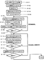
- 3 is a flowchart illustrating an operation procedure of the electron microscope according to the first embodiment.
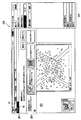
- 6 is a diagram illustrating a screen example of an operation screen according to Embodiment 1.
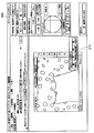
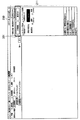
- FIG. FIG. 6 is a diagram illustrating an arrangement of operation panels on an operation screen according to the first embodiment.
- FIG. 6 is a diagram illustrating an arrangement of operation panels on an operation screen according to the first embodiment.
- FIG. 10 is a schematic diagram illustrating an example in which some operation items on an operation screen according to the second embodiment are freely arranged.
- FIG. 10 is a schematic diagram illustrating an example in which buttons of important items on an operation screen according to a third embodiment are highlighted.
- FIG. 10 is a schematic diagram illustrating another example in which buttons of important items on the operation screen according to the third embodiment are highlighted.
- FIG. 10 is a schematic diagram illustrating still another example in which buttons of important items on an operation screen according to
- the embodiment includes a charged particle source that emits a charged particle beam, a charged particle optical system that irradiates the sample with the charged particle beam, a detector that detects signal electrons generated from the sample by the irradiation of the charged particle beam, and a sample.
- the embodiment also includes a charged particle source that emits a charged particle beam, a charged particle optical system that irradiates the sample with the charged particle beam, a detector that detects signal electrons generated from the sample by the irradiation of the charged particle beam, A sample stage for holding a sample and moving the sample; a sample chamber in which the sample stage is arranged; an image display device for displaying a sample image formed based on signal electrons; a charged particle source; a charged particle optical system; A detector, a sample stage, a sample chamber, and a control unit for controlling the image display device.
- the control unit is provided with a start button for irradiating the sample with a charged particle beam to start displaying a sample image.
- a button for increasing the scanning speed of the charged particle beam and a scanning speed of the charged particle beam are displayed on the image display device from the top to the bottom in the order of the operation area, the third operation area, and the fifth operation area.
- a fourth operation area in which a button, a button for narrowing the scanning range of the charged particle beam, and a button for stopping the scanning of the charged particle beam and maintaining the display of the sample image are arranged in a desired area of the image display device.
- a charged particle beam device that displays a position.
- control unit displays on the first operation area an operation area in which a button for expanding the operation area capable of controlling the sample chamber is arranged.
- control unit displays an operation area in which a button for opening the sample chamber to the atmosphere and a button for evacuating the sample chamber are arranged on the first operation area.
- the embodiment discloses that a stop button for stopping irradiation of the charged particle beam to the sample is arranged in the first operation area.
- the embodiment discloses that a stop button for stopping irradiation of the charged particle beam to the sample is arranged in the first operation area. Further, it is disclosed that the start button and the stop button are highlighted.
- the embodiment discloses that a button for moving the sample stage is arranged in the second operation area.
- the embodiment discloses that an image indicating the position of the sample stage is displayed in the second operation area.
- the example discloses that the save button is highlighted.
- the embodiment also includes a charged particle source that emits a charged particle beam, a charged particle optical system that irradiates the sample with the charged particle beam, a detector that detects signal electrons generated from the sample surface by the irradiation of the charged particle beam, and A sample stage on which the sample is arranged and moved, a command input unit, an image display unit, an image display region for displaying a sample image formed based on signal electrons detected by the detector, and charged particles
- An operation item for photographing a sample with an optical system and a detector is displayed on the display unit with an operation panel area that displays operation items from top to bottom in the order of operation, and according to a command from the command input unit,
- a charged particle beam apparatus including a charged particle source, a charged particle optical system, a detector, a sample stage, and a control unit that controls operations of an image display unit.
- a sample image formed based on signal electrons generated from the surface of the sample by irradiation of the charged particle beam of the charged particle beam apparatus is displayed on the image display area of the image display unit, and the sample is photographed.
- An operation display method for a charged particle beam apparatus is disclosed in which an image display unit displays a screen having an operation panel area for displaying operation items from top to bottom in order of operation.
- control unit moves a specific operation item among the operation items displayed in the operation panel area to a designated position on the screen input from the operation input unit. Further, it is disclosed that the specific operation item is an operation item for confirming the visual field and the image.
- control unit displays a particular operation item in an emphasized manner compared with other operation items among the operation items displayed in the operation panel area.
- specific operation items are an operation item for observing a sample and setting an observation purpose, an operation item for confirming a visual field and an image, and an operation item for storing an image. To do.
- the first operation item for setting the observation of the sample and the observation purpose, the second operation item for grasping the display location of the sample, and the image quality are adjusted.
- a third operation item for confirming, a fourth operation item for confirming the field of view and the image, and a fifth operation item for storing the image are displayed. From the first operation item, the second operation item is displayed. It is disclosed that the operation items, the third operation item, the fourth operation item, and the fifth operation item are displayed in order from the top to the bottom.
- FIG. 1 is a schematic configuration diagram of an electron microscope according to the first embodiment.
- a primary electron beam 2 emitted from an electron gun (charged particle beam source) 1 is converged by a converging lens 3 and an objective lens 8,
- the sample 9 is scanned by the upper deflector 6 and the lower deflector 7.
- the sample 9 is placed on the sample stage 24, and signal electrons generated from the sample 9 are detected by the detector 10, and a computer (image display processing unit, operation control unit) 19 is passed through circuits 11 to 17 described later. To be supplied. Then, a signal recorded corresponding to the scanning position processed by the computer 19 is displayed on the image display device 18.
- the signal electrons include secondary electrons, reflected electrons, and transmitted electrons. It is also possible to perform elemental analysis by detecting characteristic X-rays generated from the sample 9 with an X-ray detector.
- the sample stage 24 is arranged in a sample observation chamber (not shown). In order to open or evacuate the sample observation chamber, the sample observation chamber is connected to an evacuation system including a vacuum pump (not shown).
- An X-direction astigmatism corrector 4 for performing focus X adjustment and a Y-direction astigmatism corrector 5 for performing focus Y adjustment are disposed in order to focus the primary electron beam 2 on the sample 9 in a point shape.
- the computer 19 adjusts and controls the focus X adjustment and the focus Y adjustment (astigmatism correction). Further, the computer 19 can adjust and control the excitation intensity of the converging lens 3 or the objective lens 8 to adjust the focus on the sample 9.
- the above charged particle optical system (electron gun 1, converging lens 3, X-direction astigmatism corrector 4, Y-direction astigmatism corrector 5, upper deflector 6, lower deflector 7, objective lens 8, and detector 10) It is housed in an electron microscope column (charged particle beam apparatus) 100.
- the electron optical system includes a high voltage control circuit 11, a focusing lens control circuit 12, an X direction astigmatism corrector control circuit 13, a Y direction astigmatism corrector control circuit 14, a deflector control circuit 15, and an objective lens control circuit. 16.
- the computer 19 is controlled by the computer 19 such as a CPU (Central Processing Unit) via the detection signal control circuit 17.
- the sample stage 24 and the vacuum exhaust system are also controlled by the computer 19.
- control circuits 11 to 17 may be provided separately and independently, or may be provided on one substrate. Further, each control circuit 11 to 17 may be included in the computer 19 as a function by performing the operation of each control circuit 11 to 17 by the computer 19.
- the computer 19 is connected with an image display device 18, a storage device 21, a memory 22, and an input device 23.
- an image display device 18 As will be described later, through the operation screen 200 (shown in FIG. 3) displayed on the image display device 18, the user can focus the objective lens 8, the X-direction astigmatism corrector 4, and the Y-direction astigmatism corrector 5. Adjust the astigmatism correction condition.
- the operation screen 200 according to the first embodiment is stored in advance in the storage device (storage unit) 21 corresponding to each operation stage, as will be described later.
- the operation screen 200 may be stored in another storage device connected to the network.
- an operation program 31 is stored in the memory 22, and the operation program 31 is executed by the computer 19.
- the operation program 31 displays the operation screen 200 on the image display device 18 and controls the above-described units 1 to 17 based on information input via the input device 23.
- the operation screen 200 is each screen displayed according to the user's operation stage.
- FIG. 2 is a flowchart showing the operation procedure of the electron microscope according to the first embodiment.
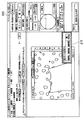
- FIG. 3 is a diagram illustrating a screen example of the operation screen according to the first embodiment.
- the operation screen 200 includes an operation navigation screen 201, an application assist screen 202, an image display screen 203, and an operation panel screen 204.
- the operation navigation screen 201 in FIG. 3 is a screen showing an operation procedure.
- the operation navigation screen 201 displays the current operation procedure as a main item A1 and a sub item A2 of the main item A1. This makes it easy for beginners to grasp the operation procedure.
- the application assist screen 202 is a screen for displaying advice on changing shooting conditions and adjusting.
- the image display screen 203 is a screen on which an image captured by an electron microscope is displayed.
- the operation panel screen 204 is a screen for changing or adjusting the shooting conditions.
- FIGS. 4 and 5 are schematic diagrams illustrating an example in which operation items in the operation panel screen 204 on the operation screen 200 are arranged from top to bottom in the order of operation.
- the operation panel screen 204 is a screen for changing or adjusting the imaging conditions.
- the “sample exchange / vacuum setting” area 211, the “observing / setting the observation purpose” area 212, and the “display location” are grasped. Items necessary for the observation operation of the charged particle beam apparatus, such as a “perform” area 213, an “automatic image adjustment” area 214, a “display mode change” area 215, and a “save” area 216, are arranged.
- the “sample exchange / vacuum setting” area 211 in FIG. 4 corresponds to step S104 in FIG. 2 and is the first operation performed among the items necessary for the subsequent observation operation.
- the setting of the sample 9 may be performed after the operation screen 200 is activated, or may be performed before the operation screen 200 is activated.
- an air release / evacuation button 301 is arranged, and a sample 9 containing the sample 9 can be observed by selecting and clicking air release or vacuuming.
- the room can be opened to the atmosphere or evacuated.
- the operation screen 200 shown in FIG. 4 is provided with a radio button 217 for switching between a high vacuum mode ( ⁇ 1 Pa) and a low vacuum mode (> 1 Pa). It can be in a vacuum state or a low vacuum state. In the low vacuum mode, two preset vacuum degrees can be selected depending on the sample to be observed.
- the “observation / set observation purpose” area 212 in FIG. 5 is used in step S105 in FIG.
- the item of this area 212 is provided with a beam on / stop button 302, which can start and stop observation.
- the observation purpose change button is clicked, the current observation conditions can be confirmed and the observation purpose can be changed.
- the current magnification and field width are displayed.
- a button for setting the magnification to a low magnification and a button for setting the magnification to a high magnification are arranged.
- a button for setting the magnification for the button for setting the current magnification to the high magnification is also arranged.
- step S105 in FIG. 2 After the observation is started by clicking the beam on button, the magnification is set to a low magnification in order to search the field of view. Thereafter, a stage operation is performed, the observation position is changed, and the magnification to be observed is set. This operation is repeated, the position where observation is desired is searched, and the magnification at which observation is desired is set.
- the “automatic image adjustment” area 214 in FIG. 5 is used in steps S105 to S113 in FIG. Items in this area 214 include an AUTO brightness button, an AUTO focus button, and an undo button. Clicking on the AUTO brightness button automatically adjusts the brightness of the image. Clicking the AUTO focus button automatically adjusts the focus of the image. In addition, by clicking the undo button, it is possible to return to the image before auto image adjustment.
- the “change display mode” area 215 in FIG. 5 is used in steps S106 to S113 in FIG.
- four types of display mode switching buttons are arranged: a visual field search button, an image confirmation button, an image adjustment button, and a pause button.
- the field search button is used when searching for a target observation field by changing the magnification and the stage position by increasing the scanning speed of the primary electron beam 2.
- the image confirmation button is used for slowing down the scanning speed of the primary electron beam 2 and confirming the image in more detail than searching for the field of view, or confirmation before acquiring the image.
- the image adjustment button is used to make it easier to confirm a change in the image during image adjustment by narrowing the scanning range of the primary electron beam 2.
- the pause button is used when scanning of the primary electron beam 2 is stopped and an image is temporarily confirmed.
- the “save” area 216 in FIG. 5 is used in step S114 in FIG.
- an image capture and save button 303 is clicked, the image currently being observed is captured and stored in the storage device 21. Even after the image is stored in the storage device 21, the image can be readjusted by pressing the “AUTO brightness” (auto brightness) button or the like in the “automatic image adjustment” area 214 again.
- AUTO brightness auto brightness
- the operation items arranged on the operation panel screen 204 shown in FIG. 3 are arranged from top to bottom in the order of operation according to the use stage of the apparatus according to the flow of FIG. Further, it is automatically folded and unfolded according to the use stage of the apparatus, or manually folded and unfolded by the user. Therefore, the user can easily recognize the buttons necessary for the operation, can grasp the series of the observation operation, and can easily perform the observation operation.
- step S101 when a user (operator) starts an operation program (not shown), an operation screen 200 shown in FIG. 4 is displayed on the image display device 18 (step S101). Then, the user selects and clicks “release to atmosphere” on the release / evacuation button 301 to set the sample (steps S102 and S103).
- step S104 when the user selects and clicks “evacuation” of the atmosphere release / evacuation button 301, the sample observation chamber is in a high vacuum state or a low vacuum state (step S104).
- the operation screen 200 is the screen shown in FIG. 5, and the user selects and clicks on the beam on / off button 302 (step S105).
- the user lowers the magnification on the magnification setting display section in the “understand display location” area 213 ((widens the observation range), step S106).
- step S107 after clicking the desired position for moving the sample stage on the circular sample stage displayed in the “Know the display location” area 213, the stage move button is clicked (step S107).
- step S108 the user increases the magnification on the magnification setting display section in the “understand display location” area 213 ((set to the magnification to be observed), step S108).
- the user confirms the image displayed on the display screen 203 and determines whether or not the field of view is acceptable (step S109). If the visual field is insufficient, the process returns to step S106, and steps S106 to S109 are executed again (visual field search again).
- step S110 and S111 the user clicks an “AUTO brightness” (auto brightness) button and an “AUTO focus” (auto focus) button in the “auto image adjustment” area 214 of FIG. 5 (steps S110 and S111).
- step S112 the user clicks the “confirm image” button in the “change display mode” area 215 of FIG. 5 (step S112).
- step S113 The user checks the image displayed on the display screen 203 and determines whether or not the image is acceptable (step S113). If the image is insufficient, the process returns to step S110, and steps S110 to S113 are executed again (adjustment and image acquisition again).
- step S114 the user clicks a button in the “save” area 216 in FIG. 5 (step S114).
- the image currently being observed is captured and stored in the storage device 21.
- step S115 the user determines whether or not the saved image is acceptable (step S115). If the image is insufficient, the process returns to step S110, and steps S110 to S115 are executed again (adjustment and image acquisition).
- step S115 If it is determined in step S115 that the image is sufficient, the process ends.
- steps S106 to S109 can be omitted.
- the computer 19 scans the sample 9 at any time with the field of view and magnification set in steps S106 to S109, acquires an image, and displays it on the image display device 18.
- the operation items on the operation screen having the operation items of the charged particle beam apparatus are arranged from top to bottom in the order in which the user operates, and the buttons are arranged in that order.
- a series of observation operations can be performed by clicking and operating.
- FIG. 6 is a diagram illustrating an operation screen 200 according to the second embodiment.
- the example shown in FIG. 6 is an example in which some operation items can be freely arranged.
- the “change display mode” area 215 arranged on the operation panel screen 204 can be taken out of the operation panel screen 204 and displayed in the image display screen area 203.
- Other configurations of the second embodiment are the same as the configurations shown in the first embodiment except that the area 215 can be taken out from the operation panel screen 204 in the image display device 18 and can be freely arranged in the other areas.
- the “change display mode” area 215 is composed of four types of display switching buttons, a visual field search button, an image confirmation button, an image adjustment button, and a pause button.
- the optimum display mode is selected automatically at each stage of steps S102 to S115 in FIG. 2 or manually with the button in the “change display mode” area 215.
- the items in the “change display mode” area 215 are used more frequently than the other display area items arranged on the operation panel screen 204, and are therefore used more frequently.
- the operation items in the operation panel screen 204 are automatically folded and unfolded depending on the stage of use of the charged particle beam apparatus, or manually folded and unfolded by the user. Therefore, in the second embodiment, the item of the “change display mode” area 215 on the operation panel screen 204 is taken out from the operation panel screen 204 and placed at an arbitrary location in the display screen of the image display device 18. It has a configuration that can.
- the item of the “understand display location” area 213 is expanded (executed), and the display mode is changed while confirming the position information of the sample stage 24 having the sample stage.
- FIGS. 7 to 9 correspond to FIGS. 4 to 6, but in the third embodiment, there is a highlighted display area in the display screen.
- the “release to atmosphere / evacuation” button 301 arranged on the operation panel screen 204 in FIG. 7, the “beam on / stop” button 302 in FIG. 8, the “load and save image” button 303, and the “ Buttons of important items such as “change display mode” area 215 are highlighted. Except for being highlighted, it is the same as that shown in the first and second embodiments.
- buttons 301 “Open to atmosphere / vacuum ”button 301 is used when exchanging the sample.
- a “beam on / stop” button 302 is used at the start and end of observation.
- An “image capture and save” button 303 is used to save an image being observed. Further, the “change display mode” region 215 is used throughout each step, as described above.
- the above operation is an operation frequently performed during the observation operation of the charged particle beam apparatus, and is an especially important item in the observation operation.
- an “atmosphere release / evacuation” button 301 in the operation panel screen 204, highlights and highlights to inform the user that it is an important button.
- the user can easily discriminate important buttons, and the observation operation can be performed smoothly.
- buttons are not limited to highlighting by color, but may be made conspicuous by increasing the font size or bolding.
- SYMBOLS 1 Electron gun, 2 ... Primary electron beam, 3 ... Condensing lens, 4 ... X direction astigmatism corrector, 5 ... Y direction astigmatism corrector, 6 ... Upper stage deflection 7 ... lower deflector, 8 ... objective lens, 9 ... sample, 10 ... detector, 11 ... high voltage control circuit, 12 ... focusing lens control circuit, 13 ... ..X direction astigmatism control circuit, 14... Y direction astigmatism control circuit, 15... Deflector control circuit, 16. , 18 ... image display device, 19 ... computer (image display unit, processing unit), 21 ... storage device (storage unit), 22 ... memory, 23 ... input device, 24 ...
Landscapes
- Chemical & Material Sciences (AREA)
- Analytical Chemistry (AREA)
- Analysing Materials By The Use Of Radiation (AREA)
- Testing Or Measuring Of Semiconductors Or The Like (AREA)
Abstract
操作初心者でも観察操作の流れをつかむことができ、一連の観察操作を簡単に行える荷電粒子線装置を実現する。試料画像を表示する画像表示装置を備えた荷電粒子線装置において、試料画像表示開始ボタンが配置される第1操作領域(212)と、試料画像観察倍率設定ボタンが配置される第2操作領域(213)と、試料画像の明るさ自動調整ボタンなどが配置される第3操作領域(214)と、荷電粒子線走査速度を早くするボタンなどが配置される第4操作領域(215)と、試料画像の記憶装置への保存ボタンが配置される第5操作領域(216)とを、順に上から下に画像表示装置に表示させる。
Description
本発明は、荷電粒子線装置に関する。
近年、走査電子顕微鏡に代表される荷電粒子線装置の用途や使用頻度が拡大しているが、それに対応できるだけの専門的な知識を持ったユーザの数は多いとはいえない。そのため、荷電粒子線装置の機能を十分に使いこなせないユーザが増加している。
上述のような問題に対し、特許文献1、2には次のような技術が記載されている。つまり、本撮影の前に、複数の簡易観察条件による撮影を行う。そして、得られた複数の簡易観察画像が表示部に一覧表示される(eプレビュー)。
続いて、ユーザが、表示されている複数の簡易観察画像の中から、所望の簡易観察画像を選択すると、コンピュータが選択された簡易観察画像における観察条件を設定する。
その後、ユーザが選択した簡易観察画像に対して必要な手動調整を行って、撮影を行う。この撮影の結果、得られた画像が表示部に表示される。
特許文献1、2に記載の技術においては、上述したように、ユーザが、表示されている複数の簡易観察画像の中から所望の簡易観察画像を選択する。
しかしながら、ユーザが初心者である場合は、表示されている複数の簡易観察画像のうち、どの画像がよいのかを認識できないことがあり、特許文献1、2に記載の技術は、このような点に考慮がなされていない。
また、ユーザが初心者である場合は、荷電粒子線の操作を行う際、どの機能を使用し、どの順番で操作をすればよいのか分からず、正しい観察像を得ることができないといった場合があるが、上記技術はこの点においても考慮がなされていない。
本発明の目的は、荷電粒子線装置の操作初心者でも観察操作の流れを掴むことができ、一連の観察操作を簡単に行うことができる荷電粒子線装置及び荷電粒子線装置の操作表示方法を実現することに関する。
本発明は、例えば、荷電粒子線を試料に照射して試料画像の表示を開始するボタンが配置される第1の操作領域と、試料画像の観察倍率を設定するボタンが配置される第2の操作領域と、試料画像の明るさを自動で調整するボタンと、試料画像の焦点を自動で調節するボタンと、試料画像の明るさと焦点を元に戻すボタンとが配置される第3の操作領域と、荷電粒子線の走査速度を早くするボタンと、荷電粒子線の走査速度を遅くするボタンと、荷電粒子線の走査範囲を狭くするボタンと、荷電粒子線の走査を停止して試料画像の表示を維持するボタンとが配置される第4の操作領域と、試料画像を記憶装置に保存するボタンが配置される第5の操作領域を、第1の操作領域から、第2の操作領域、第3の操作領域、第4の操作領域、第5の操作領域の順番で、上から下に画像表示装置に表示させる荷電粒子線装置である。
本発明によれば、荷電粒子線装置の操作初心者でも観察操作の流れを掴むことができ、一連の観察操作を簡単に行うことができる荷電粒子線装置及び荷電粒子線装置の操作表示方法を実現することができる。
実施例は、荷電粒子線を放出する荷電粒子源と、荷電粒子線を試料に照射する荷電粒子光学系と、荷電粒子線の照射によって試料から発生した信号電子を検出する検出器と、試料を保持し、試料を移動させる試料ステージと、試料ステージが配置された試料室と、信号電子に基づいて形成される試料画像を表示する画像表示装置と、荷電粒子源、荷電粒子光学系、検出器、試料ステージ、試料室、および画像表示装置を制御する制御部と、を備え、制御部が、荷電粒子線を試料に照射して試料画像の表示を開始するボタンが配置される第1の操作領域と、 試料画像の観察倍率を設定するボタンが配置される第2の操作領域と、試料画像の明るさを自動で調整するボタンと、試料画像の焦点を自動で調節するボタンと、試料画像の明るさと焦点を元に戻すボタンとが配置される第3の操作領域と、荷電粒子線の走査速度を早くするボタンと、荷電粒子線の走査速度を遅くするボタンと、荷電粒子線の走査範囲を狭くするボタンと、荷電粒子線の走査を停止して試料画像の表示を維持するボタンとが配置される第4の操作領域と、試料画像を記憶装置に保存するボタンが配置される第5の操作領域を、第1の操作領域から、第2の操作領域、第3の操作領域、第4の操作領域、第5の操作領域の順番で、上から下に画像表示装置に表示させる荷電粒子線装置を開示する。
また、実施例は、荷電粒子線を放出する荷電粒子源と、荷電粒子線を試料に照射する荷電粒子光学系と、荷電粒子線の照射によって試料から発生した信号電子を検出する検出器と、試料を保持し、試料を移動させる試料ステージと、試料ステージが配置された試料室と、信号電子に基づいて形成される試料画像を表示する画像表示装置と、荷電粒子源、荷電粒子光学系、検出器、試料ステージ、試料室、および画像表示装置を制御する制御部と、を備え、制御部は、荷電粒子線を試料に照射して試料画像の表示を開始する開始ボタンが配置される第1の操作領域と、試料画像の観察倍率を設定するボタンが配置される第2の操作領域と、試料画像の明るさを自動で調整するボタンと、試料画像の焦点を自動で調節するボタンと、試料画像の明るさと焦点を元に戻すボタンとが配置される第3の操作領域と、試料画像を記憶装置に保存するボタンが配置される第5の操作領域を、第1の操作領域から、第2の操作領域、第3の操作領域、第5の操作領域の順番で、上から下に画像表示装置に表示させ、荷電粒子線の走査速度を早くするボタンと、荷電粒子線の走査速度を遅くするボタンと、荷電粒子線の走査範囲を狭くするボタンと、荷電粒子線の走査を停止して試料画像の表示を維持するボタンとが配置される第4の操作領域を、画像表示装置の所望の位置に表示させる荷電粒子線装置を開示する。
また、実施例は、制御部が、試料室を制御できる操作領域を展開するボタンが配置される操作領域を、第1の操作領域の上に表示させることを開示する。
また、実施例は、制御部が、試料室を大気開放するボタンと、試料室を真空排気するボタンとが配置される操作領域を、第1の操作領域の上に表示させることを開示する。
また、実施例は、第1の操作領域に、荷電粒子線を試料に照射することを停止する停止ボタンが配置されることを開示する。
また、実施例は、第1の操作領域に、荷電粒子線を試料に照射することを停止する停止ボタンが配置されることを開示する。また、開始ボタンと停止ボタンが強調表示されていることを開示する。
また、実施例は、第2の操作領域に、試料ステージを移動させるボタンが配置されることを開示する。
また、実施例は、第2の操作領域に、試料ステージの位置を表示する画像が表示されることを開示する。
また、実施例は、保存ボタンが強調表示されていることを開示する。
また、実施例は、荷電粒子線を放出する荷電粒子源と、荷電粒子線を試料に照射する荷電粒子光学系と、荷電粒子線の照射によって試料表面から発生した信号電子を検出する検出器と、試料が配置され、試料を移動する試料ステージと、指令入力部と、画像表示部と、検出器により検出された信号電子に基づいて形成される試料画像を表示する画像表示領域と、荷電粒子光学系及び検出器により、試料を撮影するための、操作項目を、操作の順番に上から下に表示する操作パネル領域とを有する画面を表示部に表示させ、指令入力部からの指令に従って、荷電粒子源、荷電粒子光学系、検出器、試料ステージ、及び画像表示部の動作を制御する制御部と、を備える荷電粒子線装置を開示する。
また、実施例は、荷電粒子線装置の荷電粒子線の照射によって試料表面から発生した信号電子に基づいて形成される試料画像を画像表示部の画像表示領域に表示し、試料を撮影するための、操作項目を、操作の順番に上から下に表示する操作パネル領域を有する画面を画像表示部に表示する荷電粒子線装置の操作表示方法を開示する。
また、実施例は、制御部が、操作パネル領域に表示された操作項目のうち、特定の操作項目を操作入力部から入力された画面の指定位置に移動させることを開示する。また、特定の操作項目が、視野及び画像を確認するための操作項目であることを開示する。
また、実施例は、制御部が、操作パネル領域に表示された操作項目のうち、特定の操作項目を、他の操作項目と比較して強調して表示することを開示する。また、記特定の操作項目が、試料の観察及び観察目的を設定するための操作項目と、視野及び画像を確認するための操作項目と、画像を保存するための操作項目とであることを開示する。
また、実施例は、操作パネル領域には、試料の観察及び観察目的を設定するための第1の操作項目と、試料の表示場所を把握するための第2の操作項目と、画質を調整するための第3の操作項目と、視野及び画像を確認するための第4の操作項目と、画像を保存するための第5の操作項目とが表示され、第1の操作項目から、第2の操作項目、第3の操作項目、第4の操作項目、第5の操作項目の順番で、上から下に表示されていることを開示する。
以下、図面を用いて本発明の実施例を説明する。なお、荷電粒子線装置の一例として、電子顕微鏡を説明するが、本発明は電子顕微鏡以外にも、電子線を用いた外観検査装置、集束イオンビーム装置等の荷電粒子線装置一般に対して適用することができる。
(実施例1)
図1は、本実施例1に係る電子顕微鏡の概略構成図である。図1に示した電子顕微鏡(荷電粒子線装置、試料観察システム)101において、電子銃(荷電粒子線源)1から放射された一次電子ビーム2は、収束レンズ3および対物レンズ8によって収束され、上段偏向器6と下段偏向器7によって試料9上で走査される。
図1は、本実施例1に係る電子顕微鏡の概略構成図である。図1に示した電子顕微鏡(荷電粒子線装置、試料観察システム)101において、電子銃(荷電粒子線源)1から放射された一次電子ビーム2は、収束レンズ3および対物レンズ8によって収束され、上段偏向器6と下段偏向器7によって試料9上で走査される。
試料9は試料ステージ24上に配置され、試料9から発生した信号電子は検出器10で検出されて、後述する各回路11~17を介して、コンピュータ(画像表示処理部、動作制御部)19に供給される。そして、コンピュータ19で処理された走査位置に対応して記録された信号が画像表示装置18に表示される。なお、信号電子としては、二次電子の他、反射電子、透過電子などがある。また、試料9から発生した特性X線をX線検出器で検出して元素分析することも可能である。
試料ステージ24は、図示されていない試料観察室内に配置されている。試料観察室を大気開放や真空排気するために、試料観察室は、図示されていない真空ポンプを含む真空排気系に接続されている。
試料9上に一次電子ビーム2を点状に集束するため、フォーカスX調整を行うX方向非点補正器4と、フォーカスY調整を行うY方向非点補正器5が配置され、これらの制御条件をコンピュータ19が調整、制御することでフォーカスX調整、フォーカスY調整(非点収差補正)を行うことができる。また、収束レンズ3または対物レンズ8の励磁強度を、コンピュータ19が調整、制御することで試料9上にフォーカス調整を行うことができる。
以上の荷電粒子光学系(電子銃1、収束レンズ3、X方向非点補正器4、Y方向非点補正器5、上段偏向器6、下段偏向器7、対物レンズ8、検出器10)は電子顕微鏡カラム(荷電粒子線装置)100に収められている。
また、上記電子光学系は、高電圧制御回路11、集束レンズ制御回路12、X方向非点補正器制御回路13、Y方向非点補正器制御回路14、偏向器制御回路15、対物レンズ制御回路16、検出信号制御回路17を介して、上述したように、CPU(Central Processing Unit)などのコンピュータ19により制御されている。また、試料ステージ24や真空排気系もコンピュータ19により動作制御される。
各制御回路11~17は、別々に独立して設けられていてもよいし、一つの基板に設けられていてもよい。また、各制御回路11~17の動作をコンピュータ19により行うことにより、各制御回路11~17を機能としてコンピュータ19に含まれていてもよい。
コンピュータ19には画像表示装置18、記憶装置21、メモリ22、入力装置23が接続されている。後述するように、画像表示装置18に表示される操作画面200(図3に示す)を介して、ユーザは対物レンズ8のフォーカス条件、X方向非点補正器4およびY方向非点補正器5の非点補正条件を調整する。
また、本実施例1における操作画面200は、後述するように、各操作段階などに対応して記憶装置(記憶部)21に予め保存されている。
また、コンピュータ19がネットワークに接続されていれば、当該ネットワークに接続された別の記憶装置に操作画面200が記憶されていてもよい。
また、メモリ22には操作プログラム31が格納されており、コンピュータ19によってこの操作プログラム31が実行される。操作プログラム31は、操作画面200を画像表示装置18に表示し、入力装置23を介して入力された情報を基に、上述した各部1~17を制御する。
ここで、操作画面200とは、詳細は後述するが、ユーザの操作段階に応じて表示される各画面である。
図2は、本実施例1に係る電子顕微鏡の操作手順を示すフローチャートである。図3は、本実施例1に係る操作画面の画面例を示す図である。
図3において、操作画面200は、操作ナビ画面201と、アプリアシスト画面202と、画像表示画面203と、操作パネル画面204とを有する。
図3の操作ナビ画面201は、操作手順を示す画面である。操作ナビ画面201は、現在の操作手順を、メイン項目A1と、メイン項目A1のサブ項目A2で表示する。このようにすることで、初心者でも操作手順の把握が行いやすくなる。
アプリアシスト画面202は、撮影条件の変更や、調整に対するアドバイスを表示する画面である。画像表示画面203は、電子顕微鏡による撮影画像が表示される画面である。操作パネル画面204は、撮影条件の変更や、調整を行うための画面である。
なお、各画面201~204に表示される内容は、ユーザが行っている操作の段階によって変更される。
操作パネル画面204について、図4および図5を用いて詳細に説明する。図4および図5は、操作画面200上の操作パネル画面204内の操作項目を操作する順に上から下へ配置した例を示す概略図である。
操作パネル画面204は、撮影条件の変更や、調整を行うための画面であり、「試料交換/真空設定する」領域211、「観察する/観察目的を設定する」領域212、「表示場所を把握する」領域213、「オート画像調整する」領域214、「表示モードを変更する」領域215、「保存する」領域216といった荷電粒子線装置の観察操作に必要な項目が配置されている。
図4の「試料交換/真空設定する」領域211は、図2のステップS104に対応し、以降の観察操作に必要な項目の中で最初に行う操作である。試料9のセットは、操作画面200の起動後に行われてもよいし、操作画面200の起動前に行われてもよい。「試料交換/真空設定する」領域211の項目には、大気開放/真空引きボタン301が配置されており、大気開放又は真空引きを選択してクリックすることで、試料9が入っている試料観察室内を大気開放又は真空排気することができる。
また、図4に示した操作画面200には、高真空モード(<1Pa)と低真空モード(>1Pa)とを切り替えるラジオボタン217が配置されており、真空排気した際、試料観察室内を高真空状態または低真空状態にすることができる。低真空モードでは、観察する試料に応じて2種類のプリセットされた真空度を選択することができる。
図5の「観察する/観察目的を設定する」領域212は、図2のステップS105で使用する。この領域212の項目には、ビームオン/ストップボタン302が配置されており、観察の開始および停止を行うことができる。また、観察目的の変更ボタンをクリックすると、現在の観察条件の確認や、観察目的の変更を行うことができる。
図5の「表示場所を把握する」領域213は、図2のステップS106~S109で使用する。この領域213の上方には、現在の倍率と視野幅が表示される。また、その下には、倍率を低倍率に設定するボタンと、高倍率に設定するボタンが配置されている。高倍率に設定するボタンの右隣には、現在の倍率を高倍率に設定するボタンにかかる倍率として設定するボタンも配置されている。また、この領域213の下方には、試料台を略円形で模擬した表示があり、縦線と横線の表示により現在の試料ステージ位置を表している。この表示の右隣にはステージ移動ボタンがあり、円形の試料台の所望位置をクリックした後に当該ボタンをクリックすることで、その位置に試料ステージが移動する。図2のステップS105でビームオンボタンをクリックして観察を開始後、視野探しを行うため、倍率を低倍率に設定する。その後、ステージ操作を行い、観察位置を変更し、観察したい倍率に設定する。この操作を繰り返し、観察を行いたい位置を探し、観察したい倍率に設定する。
図5の「オート画像調整する」領域214は、図2のステップS105~S113で使用する。この領域214の項目には、AUTO明るさボタン、AUTOフォーカスボタン、元に戻すボタンが配置されている。AUTO明るさボタンをクリックすると、画像の明るさを自動で調整する。AUTOフォーカスボタンをクリックすると、画像の焦点を自動で調整する。また、元に戻すボタンをクリックすると、オート画像調整前の画像に戻すことができる。
図5の「表示モードを変更する」領域215は、図2のステップS106~S113で使用する。この領域の項目には、視野探しボタン、画像確認ボタン、画像調整ボタン、一時停止ボタンの4種類の表示モード切替ボタンが配置されている。視野探しボタンは、一次電子ビーム2の走査速度を速くして、倍率やステージ位置を変更して目的とする観察視野を探すときに使用する。画像確認ボタンは、一次電子ビーム2の走査速度を遅くして、視野探しよりも詳細な画像確認や、画像の取得前の確認に使用する。画像調整ボタンは、一次電子ビーム2の走査範囲を狭くすることで、画像調整の際の画像の変化を確認しやすくするために使用する。一時停止ボタンは、一次電子ビーム2の走査を停止し、一時的に画像を確認する場合に使用する。
図5の「保存する」領域216は、図2のステップS114で使用する。画像の取り込みと保存ボタン303をクリックすると、現在観察中の画像を取り込み、記憶装置21に記憶させる。画像を記憶装置21に記憶させた後であっても、「オート画像調整する」領域214の「AUTO明るさ」(オート明るさ)ボタン等を再度押せば、画像の再度調整が可能である。
図3に示した操作パネル画面204に配置される上記操作項目は、図2のフローに従って、装置の使用段階によって操作する順に上から下へ配置されている。また、装置の使用段階によって自動的に折りたたみ、展開、またはユーザにより手動で折りたたみ、展開がされる。そのため、ユーザは操作に必要なボタンを認識しやすく、また、観察操作の一連の流れを掴むことができ、観察操作を簡単に行うことができる。
図2を参照して、電子顕微鏡の操作手順について詳細に説明する。
まず、ユーザ(操作者)が、図示しない操作プログラムを起動すると、図4に示す操作画面200が画像表示装置18に表示される(ステップS101)。そして、ユーザが大気開放/真空引きボタン301の「大気開放」を選択してクリックし、試料をセットする(ステップS102、103)。
次に、ユーザが大気開放/真空引きボタン301の「真空引き」を選択してクリックすると、試料観察室内は高真空状態または低真空状態となる(ステップS104)。操作画面200は、図5に示す画面となり、ユーザがビームオン/ストップボタン302のビームオンを選択しクリックする(ステップS105)。次に、ユーザは、「表示場所を把握する」領域213の倍率設定表示部で倍率を下げる((観察範囲を広くする)、ステップS106)。次に、「表示場所を把握する」領域213に表示された円形の試料台上の試料台移動希望位置をクリックした後、ステージ移動ボタンをクリックする(ステップS107)。
そして、ユーザは、「表示場所を把握する」領域213の倍率設定表示部で倍率を上げる((観察したい倍率に設定する)、ステップS108)。ユーザは、表示画面203に表示された画像を確認し、視野がそれでよいか否かを判断する(ステップS109)。視野が不十分の場合は、ステップS106に戻り、ステップS106~S109を再度実行する(再度視野探し)。
次に、ユーザは、図5の「オート画像調整する」領域214の「AUTO明るさ」(オート明るさ)ボタン、「AUTOフォーカス」(オートフォーカス)ボタンをクリックする(ステップS110、S111)。
続いて、ユーザは、図5の「表示モードを変更する」領域215の「画像確認」ボタンをクリックする(ステップS112)。
ユーザは、表示画面203に表示された画像を確認し、画像がそれでよいか否かを判断する(ステップS113)。画像が不十分の場合は、ステップS110に戻り、ステップS110~S113を再度実行する(再度調整、画像取得)。
次に、ユーザは、図5の「保存する」領域216のボタンをクリックする(ステップS114)。これにより、現在観察中の画像が取り込まれ、記憶装置21に記憶される。ユーザは「保存する」領域216のボタンをクリックした後、保存した画像がそれでよいか否かを判断する(ステップS115)。画像が不十分の場合は、ステップS110に戻り、ステップS110~S115を再度実行する(再度調整、画像取得)。
ステップS115において、画像が十分であると判断された場合は処理は終了する。
なお、視野・倍率も自動で設定している場合、ステップS106~S109の処理は省略可能である。
また、コンピュータ19は、ステップS106~S109で設定された視野や倍率で随時、試料9を走査し、画像を取得し、画像表示装置18に表示している。
以上のように、本発明の実施例1によれば、荷電粒子線装置の操作項目を有する操作画面上の操作項目が、ユーザが操作する順に上から下へ配置されており、その順番でボタンをクリックして操作することにより、一連の観察操作を行うことができる。
したがって、荷電粒子線装置の操作初心者でも観察操作の流れを掴むことができ、一連の観察操作を簡単に行うことができる荷電粒子線装置及び荷電粒子線装置の操作表示方法を実現することができる。
(実施例2)
次に、本発明の第2の実施例について説明する。
次に、本発明の第2の実施例について説明する。
図6は、本実施例2に係る操作画面200を示す図である。図6に示した例は、操作項目の一部を自由配置できる例である。
図6において、操作パネル画面204に配置されている「表示モードを変更する」領域215を操作パネル画面204から取り出して、画像表示画面領域203に表示することができる。実施例2のその他の構成は、画像表示装置18内で領域215を操作パネル画面204から取り出して、その他の領域に自由に配置できる点以外は、実施例1で示した構成と同様である。
「表示モードを変更する」領域215は、視野探しボタン、画像確認ボタン、画像調整ボタン、一時停止ボタンの4種類の表示切り替えボタンにより構成される。図2のステップS102~S115の各段階で最適な表示モードを自動または、「表示モードを変更する」領域215のボタンにより手動で選択する。
「表示モードを変更する」領域215の項目は、操作パネル画面204に配置されたその他の表示領域の項目に比べ、図2に示した各ステップにわたり使用するため、使用頻度が高い。
また、操作パネル画面204内の操作項目は、荷電粒子線装置の使用段階によって自動的に折りたたみと展開、またはユーザにより手動で折りたたみと展開がされる。そこで、本実施例2では、操作パネル画面204において、「表示モードを変更する」領域215の項目を、操作パネル画面204から取り出し、画像表示装置18の表示画面内の任意の場所に配置することができる構成となっている。
本実施例2の構成を用いることで、「表示場所を把握する」領域213の項目を展開し(実行し)、試料台を有する試料ステージ24の位置情報を確認しながら表示モードの変更を行うことや、「オート画像調整する」領域214の項目を展開して画像のオート調整をしながら表示モードの変更を行うことを、操作パネル画面204の操作項目の折りたたみと展開を行うことなく、表示モードの変更を行うことが可能となる。
本実施例2においても、実施例1と同様な効果を得ることができる。
(実施例3)
次に、本発明の実施例3について、図7~図9を用いて説明する。図7~図9は、図4~図6に対応するが、本実施例3においては、表示画面のなかで、強調表示されている表示領域がある。
次に、本発明の実施例3について、図7~図9を用いて説明する。図7~図9は、図4~図6に対応するが、本実施例3においては、表示画面のなかで、強調表示されている表示領域がある。
つまり、図7の、操作パネル画面204に配置されている「大気開放/真空引き」ボタン301、図8の「ビームオン/ストップ」ボタン302、「画像の取り込みと保存」ボタン303、図9の「表示モードを変更する」領域215といった重要な項目のボタンが強調表示されている。強調表示されているという点以外は実施例1、実施例2で示したものと同様である。
「大気開放/真空引き」ボタン301は、試料を交換する時に使用する。また、「ビームオン/ストップ」ボタン302は、観察の開始時および終了時に使用する。また、「画像の取り込みと保存」ボタン303は、観察中の像を保存する時に使用する。さらに、「表示モードを変更する」領域215は、上述したように、各ステップにわたり使用される。
上記操作は、荷電粒子線装置の観察操作時に頻繁に行う操作であり、観察操作の中でも特に重要な項目である。しかし、他のボタンと同様の表記とした場合、操作初心者に限らず、一般ユーザにおいても、ボタンを探し出すことが困難となる。
そこで、本実施例3では、操作パネル画面204において、「大気開放/真空引き」ボタン301、「ビームオン/ストップ」ボタン302、「画像の取り込みと保存」ボタン303、「表示モードを変更する」領域215は強調表示して目立たせることで、ユーザに重要なボタンであることを知らせる。
本実施例3によれば、ユーザは重要なボタンを簡単に判別でき、観察操作をスムーズに行うことが可能となる。
なお、本実施例3の構成において、重要なボタンは色彩による強調表示に限らず、フォントサイズを大きくすることや、太字とするなどして目立たせてもよい。
本実施例3においても、実施例1と同様な効果を得ることができる。
1・・・電子銃、2・・・一次電子ビーム、3・・・集束レンズ、4・・・X方向非点補正器、5・・・Y方向非点補正器、6・・・上段偏向器、7・・・下段偏向器、8・・・対物レンズ、9・・・試料、10・・・検出器、11・・・高電圧制御回路、12・・・集束レンズ制御回路、13・・・X方向非点補正器制御回路、14・・・Y方向非点補正器制御回路、15・・・偏向器制御回路、16・・・対物レンズ制御回路、17・・・検出信号制御回路、18・・・画像表示装置、19・・・コンピュータ(画像表示部、処理部)、21・・・記憶装置(記憶部)、22・・・メモリ、23・・・入力装置、24・・・試料ステージ、31・・・操作プログラム、41・・・観察条件設定テーブル、100・・・電子顕微鏡カラム(荷電粒子線装置)、101・・・電子顕微鏡(荷電粒子線装置、荷電粒子線装置システム)、200・・・操作画面、201・・・操作ナビ画面、202・・・アプリアシスト画面、203・・・画像表示画面、204・・・操作パネル画面
Claims (10)
- 荷電粒子線を放出する荷電粒子源と、
前記荷電粒子線を試料に照射する荷電粒子光学系と、
前記荷電粒子線の照射によって試料から発生した信号電子を検出する検出器と、
前記試料を保持し、試料を移動させる試料ステージと、
前記試料ステージが配置された試料室と、
前記信号電子に基づいて形成される試料画像を表示する画像表示装置と、
前記荷電粒子源、前記荷電粒子光学系、前記検出器、前記試料ステージ、前記試料室、および前記画像表示装置を制御する制御部と、
を備え、
前記制御部は、
前記荷電粒子線を試料に照射して前記試料画像の表示を開始するボタンが配置される第1の操作領域と、
前記試料画像の観察倍率を設定するボタンが配置される第2の操作領域と、
前記試料画像の明るさを自動で調整するボタンと、前記試料画像の焦点を自動で調節するボタンと、前記試料画像の明るさと焦点を元に戻すボタンとが配置される第3の操作領域と、
前記荷電粒子線の走査速度を早くするボタンと、前記荷電粒子線の走査速度を遅くするボタンと、前記荷電粒子線の走査範囲を狭くするボタンと、前記荷電粒子線の走査を停止して前記試料画像の表示を維持するボタンとが配置される第4の操作領域と、
前記試料画像を記憶装置に保存するボタンが配置される第5の操作領域を、
前記第1の操作領域から、前記第2の操作領域、前記第3の操作領域、前記第4の操作領域、前記第5の操作領域の順番で、上から下に前記画像表示装置に表示させる
ことを特徴とする荷電粒子線装置。 - 荷電粒子線を放出する荷電粒子源と、
前記荷電粒子線を試料に照射する荷電粒子光学系と、
前記荷電粒子線の照射によって試料から発生した信号電子を検出する検出器と、
前記試料を保持し、試料を移動させる試料ステージと、
前記試料ステージが配置された試料室と、
前記信号電子に基づいて形成される試料画像を表示する画像表示装置と、
前記荷電粒子源、前記荷電粒子光学系、前記検出器、前記試料ステージ、前記試料室、および前記画像表示装置を制御する制御部と、
を備え、
前記制御部は、
前記荷電粒子線を試料に照射して前記試料画像の表示を開始する開始ボタンが配置される第1の操作領域と、
前記試料画像の観察倍率を設定するボタンが配置される第2の操作領域と、
前記試料画像の明るさを自動で調整するボタンと、前記試料画像の焦点を自動で調節するボタンと、前記試料画像の明るさと焦点を元に戻すボタンとが配置される第3の操作領域と、
前記試料画像を記憶装置に保存するボタンが配置される第5の操作領域を、
前記第1の操作領域から、前記第2の操作領域、前記第3の操作領域、前記第5の操作領域の順番で、上から下に前記画像表示装置に表示させ、
前記荷電粒子線の走査速度を早くするボタンと、前記荷電粒子線の走査速度を遅くするボタンと、前記荷電粒子線の走査範囲を狭くするボタンと、前記荷電粒子線の走査を停止して前記試料画像の表示を維持するボタンとが配置される第4の操作領域を、
前記画像表示装置の所望の位置に表示させる
ことを特徴とする荷電粒子線装置。 - 請求項1または2のいずれかに記載の荷電粒子線装置において、
前記制御部は、前記試料室を制御できる操作領域を展開するボタンが配置される操作領域を、前記第1の操作領域の上に表示させることを特徴とする荷電粒子線装置。 - 請求項1または2のいずれかに記載の荷電粒子線装置において、
前記制御部は、前記試料室を大気開放するボタンと、前記試料室を真空排気するボタンとが配置される操作領域を、前記第1の操作領域の上に表示させることを特徴とする荷電粒子線装置。 - 請求項1または2のいずれかに記載の荷電粒子線装置において、
前記第1の操作領域に、前記荷電粒子線を試料に照射することを停止する停止ボタンが配置されることを特徴とする荷電粒子線装置。 - 請求項1または2のいずれかに記載の荷電粒子線装置において、
前記第1の操作領域に、前記荷電粒子線を試料に照射することを停止する停止ボタンが配置されることを特徴とする荷電粒子線装置。 - 請求項6記載の荷電粒子線装置において、
前記開始ボタンと前記停止ボタンが強調表示されていることを特徴とする荷電粒子線装置。 - 請求項1または2のいずれかに記載の荷電粒子線装置において、
前記第2の操作領域に、前記試料ステージを移動させるボタンが配置されることを特徴とする荷電粒子線装置。 - 請求項1または2のいずれかに記載の荷電粒子線装置において、
前記第2の操作領域に、前記試料ステージの位置を表示する画像が表示されることを特徴とする荷電粒子線装置。 - 請求項1または2のいずれかに記載の荷電粒子線装置において、
前記保存ボタンが強調表示されていることを特徴とする荷電粒子線装置。
Applications Claiming Priority (2)
| Application Number | Priority Date | Filing Date | Title |
|---|---|---|---|
| JP2013159337A JP5464536B1 (ja) | 2013-07-31 | 2013-07-31 | 荷電粒子線装置及び荷電粒子線装置の操作表示方法 |
| JP2013-159337 | 2013-07-31 |
Publications (1)
| Publication Number | Publication Date |
|---|---|
| WO2015015853A1 true WO2015015853A1 (ja) | 2015-02-05 |
Family
ID=50619411
Family Applications (1)
| Application Number | Title | Priority Date | Filing Date |
|---|---|---|---|
| PCT/JP2014/062104 Ceased WO2015015853A1 (ja) | 2013-07-31 | 2014-05-01 | 荷電粒子線装置及び荷電粒子線装置の操作表示方法 |
Country Status (2)
| Country | Link |
|---|---|
| JP (1) | JP5464536B1 (ja) |
| WO (1) | WO2015015853A1 (ja) |
Citations (3)
| Publication number | Priority date | Publication date | Assignee | Title |
|---|---|---|---|---|
| JPS54148397A (en) * | 1978-05-12 | 1979-11-20 | Jeol Ltd | Electron microscope and its analogous device |
| JPH0982263A (ja) * | 1995-09-14 | 1997-03-28 | Hitachi Ltd | 電子顕微鏡 |
| WO2011108042A1 (ja) * | 2010-03-05 | 2011-09-09 | 株式会社 日立ハイテクノロジーズ | 電子顕微鏡画像と光学画像を重ねて表示する方法 |
-
2013
- 2013-07-31 JP JP2013159337A patent/JP5464536B1/ja active Active
-
2014
- 2014-05-01 WO PCT/JP2014/062104 patent/WO2015015853A1/ja not_active Ceased
Patent Citations (3)
| Publication number | Priority date | Publication date | Assignee | Title |
|---|---|---|---|---|
| JPS54148397A (en) * | 1978-05-12 | 1979-11-20 | Jeol Ltd | Electron microscope and its analogous device |
| JPH0982263A (ja) * | 1995-09-14 | 1997-03-28 | Hitachi Ltd | 電子顕微鏡 |
| WO2011108042A1 (ja) * | 2010-03-05 | 2011-09-09 | 株式会社 日立ハイテクノロジーズ | 電子顕微鏡画像と光学画像を重ねて表示する方法 |
Also Published As
| Publication number | Publication date |
|---|---|
| JP5464536B1 (ja) | 2014-04-09 |
| JP2015032374A (ja) | 2015-02-16 |
Similar Documents
| Publication | Publication Date | Title |
|---|---|---|
| JP5698157B2 (ja) | 荷電粒子線装置および傾斜観察画像表示方法 | |
| US10020163B2 (en) | Charged particle beam apparatus, specimen observation system and operation program | |
| CN109906497B (zh) | 带电粒子束装置以及试样观察方法 | |
| CN104838466A (zh) | 带电粒子束装置以及程序 | |
| CN104137220B (zh) | 带电粒子束装置、试样观察系统以及操作程序 | |
| US6800853B2 (en) | Electron microscope and method of photographing TEM images | |
| JP6716026B2 (ja) | 荷電粒子線装置および荷電粒子線装置における条件設定方法 | |
| JP5464536B1 (ja) | 荷電粒子線装置及び荷電粒子線装置の操作表示方法 | |
| JP5490333B1 (ja) | 荷電粒子線装置、荷電粒子線装置の試料観察方法および荷電粒子線装置の表示制御プログラム | |
| JP6121704B2 (ja) | 荷電粒子線装置 | |
| JP6159273B2 (ja) | 荷電粒子線装置、荷電粒子線装置の試料観察方法および荷電粒子線装置の表示制御プログラム | |
| EP3091505A1 (en) | Image processor, electron microscope, and image processing method | |
| JP4668807B2 (ja) | 荷電粒子線装置及び荷電粒子線画像生成方法 | |
| JP4111778B2 (ja) | 集束イオンビーム装置により一部が薄膜状に加工された試料の電子顕微鏡による観察方法 | |
| JP4050948B2 (ja) | 電子顕微鏡 | |
| JPH10302704A (ja) | 荷電粒子ビーム装置 | |
| JP2012114014A (ja) | 荷電ビーム装置、及び荷電ビーム装置の画像表示方法 | |
| JP5502794B2 (ja) | 電子顕微鏡 | |
| JP2004220988A (ja) | 電子顕微鏡、電子顕微鏡の操作方法、電子顕微鏡の操作プログラムおよびコンピュータで読み取り可能な記録媒体 | |
| JP4223734B2 (ja) | 電子顕微鏡 | |
| JPH07254387A (ja) | 走査型荷電粒子線顕微鏡 | |
| JP2001093458A (ja) | 透過型電子顕微鏡における電子ビーム調整方法 | |
| JPH06283126A (ja) | 走査電子顕微鏡 |
Legal Events
| Date | Code | Title | Description |
|---|---|---|---|
| 121 | Ep: the epo has been informed by wipo that ep was designated in this application |
Ref document number: 14831721 Country of ref document: EP Kind code of ref document: A1 |
|
| NENP | Non-entry into the national phase |
Ref country code: DE |
|
| 122 | Ep: pct application non-entry in european phase |
Ref document number: 14831721 Country of ref document: EP Kind code of ref document: A1 |