WO2015015666A1 - Actuator device and mirror drive device - Google Patents
Actuator device and mirror drive device Download PDFInfo
- Publication number
- WO2015015666A1 WO2015015666A1 PCT/JP2013/083362 JP2013083362W WO2015015666A1 WO 2015015666 A1 WO2015015666 A1 WO 2015015666A1 JP 2013083362 W JP2013083362 W JP 2013083362W WO 2015015666 A1 WO2015015666 A1 WO 2015015666A1
- Authority
- WO
- WIPO (PCT)
- Prior art keywords
- wiring
- torsion bar
- straight
- movable
- disposed
- Prior art date
Links
Images


Classifications
-
- G—PHYSICS
- G02—OPTICS
- G02B—OPTICAL ELEMENTS, SYSTEMS OR APPARATUS
- G02B26/00—Optical devices or arrangements for the control of light using movable or deformable optical elements
- G02B26/08—Optical devices or arrangements for the control of light using movable or deformable optical elements for controlling the direction of light
- G02B26/0816—Optical devices or arrangements for the control of light using movable or deformable optical elements for controlling the direction of light by means of one or more reflecting elements
- G02B26/0833—Optical devices or arrangements for the control of light using movable or deformable optical elements for controlling the direction of light by means of one or more reflecting elements the reflecting element being a micromechanical device, e.g. a MEMS mirror, DMD
- G02B26/085—Optical devices or arrangements for the control of light using movable or deformable optical elements for controlling the direction of light by means of one or more reflecting elements the reflecting element being a micromechanical device, e.g. a MEMS mirror, DMD the reflecting means being moved or deformed by electromagnetic means
-
- B—PERFORMING OPERATIONS; TRANSPORTING
- B81—MICROSTRUCTURAL TECHNOLOGY
- B81B—MICROSTRUCTURAL DEVICES OR SYSTEMS, e.g. MICROMECHANICAL DEVICES
- B81B3/00—Devices comprising flexible or deformable elements, e.g. comprising elastic tongues or membranes
- B81B3/0035—Constitution or structural means for controlling the movement of the flexible or deformable elements
- B81B3/004—Angular deflection
- B81B3/0045—Improve properties related to angular swinging, e.g. control resonance frequency
-
- G—PHYSICS
- G02—OPTICS
- G02B—OPTICAL ELEMENTS, SYSTEMS OR APPARATUS
- G02B26/00—Optical devices or arrangements for the control of light using movable or deformable optical elements
- G02B26/08—Optical devices or arrangements for the control of light using movable or deformable optical elements for controlling the direction of light
- G02B26/0816—Optical devices or arrangements for the control of light using movable or deformable optical elements for controlling the direction of light by means of one or more reflecting elements
-
- G—PHYSICS
- G02—OPTICS
- G02B—OPTICAL ELEMENTS, SYSTEMS OR APPARATUS
- G02B26/00—Optical devices or arrangements for the control of light using movable or deformable optical elements
- G02B26/08—Optical devices or arrangements for the control of light using movable or deformable optical elements for controlling the direction of light
- G02B26/10—Scanning systems
- G02B26/101—Scanning systems with both horizontal and vertical deflecting means, e.g. raster or XY scanners
-
- H—ELECTRICITY
- H02—GENERATION; CONVERSION OR DISTRIBUTION OF ELECTRIC POWER
- H02K—DYNAMO-ELECTRIC MACHINES
- H02K33/00—Motors with reciprocating, oscillating or vibrating magnet, armature or coil system
- H02K33/18—Motors with reciprocating, oscillating or vibrating magnet, armature or coil system with coil systems moving upon intermittent or reversed energisation thereof by interaction with a fixed field system, e.g. permanent magnets
-
- B—PERFORMING OPERATIONS; TRANSPORTING
- B81—MICROSTRUCTURAL TECHNOLOGY
- B81B—MICROSTRUCTURAL DEVICES OR SYSTEMS, e.g. MICROMECHANICAL DEVICES
- B81B2201/00—Specific applications of microelectromechanical systems
- B81B2201/04—Optical MEMS
- B81B2201/042—Micromirrors, not used as optical switches
-
- B—PERFORMING OPERATIONS; TRANSPORTING
- B81—MICROSTRUCTURAL TECHNOLOGY
- B81B—MICROSTRUCTURAL DEVICES OR SYSTEMS, e.g. MICROMECHANICAL DEVICES
- B81B2203/00—Basic microelectromechanical structures
- B81B2203/01—Suspended structures, i.e. structures allowing a movement
- B81B2203/0145—Flexible holders
- B81B2203/0154—Torsion bars
-
- G—PHYSICS
- G02—OPTICS
- G02B—OPTICAL ELEMENTS, SYSTEMS OR APPARATUS
- G02B26/00—Optical devices or arrangements for the control of light using movable or deformable optical elements
- G02B26/08—Optical devices or arrangements for the control of light using movable or deformable optical elements for controlling the direction of light
- G02B26/0816—Optical devices or arrangements for the control of light using movable or deformable optical elements for controlling the direction of light by means of one or more reflecting elements
- G02B26/0833—Optical devices or arrangements for the control of light using movable or deformable optical elements for controlling the direction of light by means of one or more reflecting elements the reflecting element being a micromechanical device, e.g. a MEMS mirror, DMD
- G02B26/0858—Optical devices or arrangements for the control of light using movable or deformable optical elements for controlling the direction of light by means of one or more reflecting elements the reflecting element being a micromechanical device, e.g. a MEMS mirror, DMD the reflecting means being moved or deformed by piezoelectric means
Definitions
- the present invention relates to an actuator device and a mirror driving device.
- a support part, a movable part in which the coil is arranged, a magnetic field generating part for applying a magnetic field to the coil, a wiring connected to the coil, and a torsion bar part for slidably coupling the movable part to the support part; are known (see, for example, Patent Document 1).
- the torsion bar portion has a meandering shape having a plurality of straight portions and a plurality of folded portions.
- the plurality of straight portions extend in the first direction along the swing axis of the torsion bar portion, and are juxtaposed in the second direction intersecting the first direction.
- the plurality of folded portions alternately connect both ends of the plurality of straight portions.
- the present inventors have newly found the following facts as a result of research.
- the wiring arranged in the torsion bar part is connected to the wiring part arranged in each folded part, the wiring part and the straight part.
- the wiring portion arranged in the folded portion has a higher resistance than the wiring portion arranged in the straight portion due to its shape. For this reason, the wiring part arrange
- turning part has high resistance in the whole wiring. If the resistance of the wiring is high, the wiring generates heat and it is difficult to secure a sufficient amount of current to be supplied to the coil. When a sufficient amount of current to the coil cannot be secured, the swing range of the movable part becomes narrow.
- the wiring is a damascene wiring made of copper (Cu)
- Cu copper
- the wiring may hinder the swinging of the movable portion.
- the straight portion extending in the first direction along the swing shaft of the torsion bar portion is large. Stress acts. For this reason, for example, when the movable portion swings in one direction around the swing axis of the torsion bar portion, a large stress acts on the damascene wiring made of Cu, which is located in the straight portion, and the damascene wiring made of Cu itself Is plastically deformed.
- the movable part When the wiring (damascene wiring) is plastically deformed, the movable part may not return to the initial position, or when the movable part swings in a direction opposite to the one direction around the swing axis of the torsion bar part. Resistance may occur.
- the inventors of the present invention have made extensive studies on a configuration that can reduce the resistance of the wiring and can suppress the wiring from inhibiting the swinging of the movable portion.
- the present inventors have come up with a configuration that can suppress plastic deformation of the wiring portion located in the straight portion.
- the wiring portion arranged in the straight portion to which a large stress acts is not a damascene wiring made of Cu but a wiring made of a metal material that is less likely to undergo plastic deformation than Cu.
- the inventors of the present invention noted that the stress acting on the folded portion is lower than that of the straight portion.
- the present inventors have conceived that the resistance of the wiring can be reduced by adopting a configuration in which the wiring portion arranged in the folded portion is a damascene wiring made of Cu.
- the wiring portion arranged in the folded portion has a relatively high resistance due to its shape. For this reason, when the wiring part arrange
- An actuator device includes a torsion bar portion that includes a support portion, a movable portion on which a conductor is disposed, and a wiring connected to the conductor, and that swingably connects the movable portion to the support portion
- a torsion bar portion extending in a first direction along the swing axis of the torsion bar portion, and a plurality of straight portions juxtaposed in a second direction intersecting the first direction, and a plurality of straight portions
- a plurality of folded portions that alternately connect both ends of the wire, and a wiring is connected to the first wiring portion and the first wiring portion arranged in each folded portion, and each straight shape
- the first wiring portion arranged in the folded portion includes a damascene wiring portion made of a first metal material made of Cu. For this reason, resistance reduction of the wiring arrange
- positioned at a straight-shaped part is comprised with the 2nd metal material which is hard to carry out plastic deformation rather than a 1st metal material. For this reason, even when a large stress acts on the straight portion, the plastic deformation of the second wiring portion is suppressed. Therefore, it can suppress that the wiring arrange
- the first wiring portion may further include a portion that is disposed on the damascene wiring portion so as to cover the opening of the groove and is configured by the second metal material. In this case, the resistance of the first wiring portion can be further reduced.
- the corner edge located on the surface side of the folded portion is locally thinned, and the cross-sectional area may be reduced.
- the resistance of the first wiring portion increases.
- the first wiring portion further includes a portion arranged on the damascene wiring portion so as to cover the opening of the groove, even when the damascene wiring portion is thinned, the resistance of the first wiring portion is high. Can be prevented.
- connection location between the torsion bar portion and the support portion and the connection location between the torsion bar portion and the movable portion may be located on a virtual line extending in the first direction through the central portion in the second direction of the torsion bar portion.
- the resonance frequency of the torsion bar part is determined by the width of the torsion bar part and the length of the torsion bar part in the first direction.
- the straight portions are juxtaposed not in the first direction but in the second direction. For this reason, even when the number of straight directions is increased, the length of the torsion bar portion in the first direction does not change. Therefore, the torsion bar part can be easily designed to set the resonance frequency of the torsion bar part to a desired value.
- the torsion bar portion includes a first connecting portion that connects one of the plurality of straight portions located on the outermost side in the second direction and the support portion, and a second portion of the plurality of straight portions in the second direction. And a second connection portion for connecting the other straight portion located on the outermost side and the movable portion, and the wiring is connected to the first wiring portion and arranged in the first and second connection portions, respectively. It may further have a third wiring portion.
- the third wiring portion may include a damascene wiring portion that is disposed so as to be embedded in grooves formed in the first and second connection portions, respectively, and is configured of a first metal material. In this case, even when the wiring has the third wiring portion, the resistance of the wiring is suppressed from increasing. As a result, the resistance of the wiring can be reliably reduced.
- the second metal material may be made of Al or an alloy containing Al. In this case, the plastic deformation of the second wiring portion can be suppressed extremely well.
- the movable part has a first part to which the torsion bar part is coupled, and a second part supported by the first part so as to be swingable about a swing axis extending in a direction perpendicular to the swing axis of the torsion bar part. You may do it.
- the second part of the movable part can be swung around two orthogonal axes.
- the movable part may be further provided with a magnetic field generating part for arranging a coil as a conductor and applying a magnetic field to the coil.
- the movable part can be swung by passing a current through the coil on which the magnetic field acts.
- a mirror driving device is a mirror driving device, and includes the actuator device and a mirror disposed on a movable portion.
- the mirror driving device as described above, it is possible to reduce the resistance of the wiring arranged in the torsion bar portion, and the wiring arranged in the torsion bar portion swings the movable portion. Inhibiting movement can be suppressed.
- an actuator device and a mirror driving device capable of reducing the resistance of the wiring and suppressing the wiring from inhibiting the swing of the movable portion.
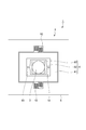
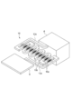
- FIG. 1 is a perspective view showing a mirror driving device according to an embodiment of the present invention.
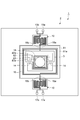
- FIG. 2 is a top view of the mirror driving device shown in FIG.
- FIG. 3 is a diagram for explaining a circuit in the mirror driving device shown in FIG.
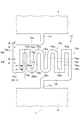
- FIG. 4 is a diagram for explaining the configuration of the torsion bar unit.
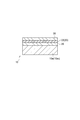
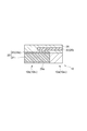
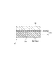
- FIG. 5 is a view for explaining a cross-sectional configuration along the line VV in FIG.
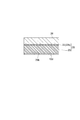
- FIG. 6 is a view for explaining a cross-sectional configuration along the line VI-VI in FIG.
- FIG. 7 is a view for explaining a cross-sectional configuration along the line VII-VII in FIG.
- FIG. 8 is a diagram for explaining a cross-sectional configuration along the line VIII-VIII in FIG.
- FIG. 5 is a view for explaining a cross-sectional configuration along the line VV in FIG.
- FIG. 6 is a view for explaining a cross-sectional configuration along the line VI-VI in FIG.
- FIG. 7 is
- FIG. 9 is a diagram for explaining a cross-sectional configuration along the line IX-IX in FIG.
- FIG. 10 is a diagram for explaining a cross-sectional configuration along the line XX of FIG.
- FIG. 11 is a diagram for explaining a state of stress generated in the torsion bar portion.
- FIG. 12 is a diagram for explaining a modification of the configuration of the wiring.
- FIG. 13 is a diagram for explaining a modification of the configuration of the wiring.
- FIG. 1 is a perspective view showing a mirror driving device according to the present embodiment.
- FIG. 2 is a top view of the mirror driving device shown in FIG.
- FIG. 3 is a diagram for explaining a circuit in the mirror driving device shown in FIG.
- the mirror driving device 1 includes an actuator device 2 and a mirror 3.
- the actuator device 2 includes a magnetic field generation unit 4, a support unit 6, a movable unit 8, and a pair of torsion bar units 10.
- the mirror 3 is a light reflecting film composed of a metal thin film.
- the mirror 3 has a circular shape in plan view.
- Examples of the metal material used for the mirror 3 include aluminum (Al), gold (Au), and silver (Ag).
- the magnetic field generator 4 is a flat plate having a rectangular shape.
- the magnetic field generator 4 has a pair of main surfaces 4a and 4b (not shown).
- the magnetic field generator 4 applies a magnetic field to the movable part 8.
- a Halbach array is adopted as the magnetic pole array in the magnetic field generator 4.
- the magnetic field generation unit 4 is configured by, for example, a permanent magnet.
- the support part 6 is a frame body whose outer contour has a rectangular shape.
- the support 6 is disposed on the magnetic field generator 4 so as to face the main surface 4a.
- the support portion 6 supports the movable portion 8 via a pair of torsion bar portions 10.
- the movable part 8 is located inside the support part 6.
- the movable part 8 has a first movable part 81, a second movable part 82, and a mirror arrangement part 83.
- the support part 6, the movable part 8, and the torsion bar part 10 are integrally formed, and are made of, for example, silicon (Si).
- the first movable portion 81 is a flat frame body that is located inside the support portion 6 and has a rectangular outer contour.
- the first movable portion 81 is connected to the torsion bar portion 10 and is spaced apart from the support portion 6.
- the first movable portion 81 is swingably supported by the support portion 6 via a pair of torsion bar portions 10. That is, the first movable portion 81 is supported by the support portion 6 via the pair of torsion bar portions 10 so as to be capable of reciprocating rotation.
- Each torsion bar portion 10 connects the first movable portion 81 to the support portion 6 in a swingable manner.
- the first movable portion 81 has a main surface that faces the magnetic field generator 4 and a main surface 81a that is the back surface of the main surface.
- Each torsion bar portion 10 has a meandering shape as described later.
- the second movable part 82 is a flat frame body that is located inside the first movable part 81 and has an outer contour that is rectangular.
- the second movable part 82 is disposed away from the first movable part 81.
- the second movable portion 82 is swingably supported by the first movable portion 81 via the pair of torsion bar portions 14. That is, the second movable portion 82 is supported by the first movable portion 81 through the pair of torsion bar portions 14 so as to be capable of reciprocating rotation.
- Each torsion bar portion 14 connects the second movable portion 82 to the first movable portion 81 so as to be swingable.
- the second movable portion 82 also has a main surface that faces the magnetic field generation unit 4 and a main surface 82a that is the back surface of the main surface.
- Each torsion bar portion 14 has a straight shape and is located on the same straight line.
- the torsion bar portion 14 is also formed integrally with the support portion 6, the movable portion 8, and the torsion bar portion 10, and is made of, for example, Si.
- the rocking axis of the torsion bar unit 10 intersects the rocking axis of the torsion bar unit 14.
- the swing axis of the torsion bar unit 10 is orthogonal to the swing axis of the torsion bar unit 14. That is, the rotation axis of the torsion bar unit 10 intersects with the rotation axis of the torsion bar unit 14.
- the second movable portion 82 is supported by the first movable portion 81 so as to be swingable around a swing shaft extending in a direction orthogonal to the swing shaft of the torsion bar portion 10.
- the mirror arrangement portion 83 is located inside the second movable portion 82 and has a circular shape.
- the mirror arrangement portion 83 is integrated with the second movable portion 82 and swings integrally with the second movable portion 82.
- the mirror arrangement portion 83 has a main surface that faces the magnetic field generator 4 and a main surface 83a that is the back surface of the main surface.
- the mirror 3 is arranged on the main surface 83 a of the mirror arrangement portion 83.
- the actuator device 2 (mirror drive device 1) includes a coil 16 disposed in the first movable portion 81 and a coil 18 disposed in the second movable portion 82. .
- the coil 16 is disposed on the main surface 81 a side of the first movable part 81.
- the coil 18 is disposed on the main surface 82 a side of the second movable portion 82.
- the coil 16 is used as a conductor arranged in the first movable part 81
- the coil 18 is used as a conductor arranged in the second movable part 82.
- the coil 16 is wound in a plurality of rounds in a spiral shape when viewed from the direction orthogonal to the main surface 81a. One end of the coil 16 is located outside the coil 16, and the other end of the coil 16 is located inside the coil 16. One end of a lead conductor 16 a is electrically connected to the outer end portion of the coil 16. One end of the lead conductor 16 b is electrically connected to the inner end of the coil 16.
- the lead conductors 16 a and 16 b are mainly disposed on one torsion bar portion 10 and reach the support portion 6 from the first movable portion 81.
- the other ends of the lead conductors 16 a and 16 b are electrically connected to electrodes 17 a and 17 b arranged on the surface of the support portion 6.
- the electrodes 17a and 17b are electrically connected to a control circuit (not shown).
- the lead conductor 16a crosses the coil 16 three-dimensionally so as to pass above the coil 16.
- the coil 18 is wound a plurality of times in a spiral shape when viewed from the direction orthogonal to the main surface 82a. One end of the coil 18 is located outside the coil 18, and the other end of the coil 18 is located inside the coil 18. One end of the lead conductor 18 a is electrically connected to the outer end of the coil 18. One end of the lead conductor 18 b is electrically connected to the inner end of the coil 18.
- the lead conductors 18a and 18b are mainly disposed on the torsion bar portion 14, the first movable portion 81, and the one torsion bar portion 10, and extend from the second movable portion 82 to the other torsion bar portion 10.
- the other ends of the lead conductors 18 a and 18 b are electrically connected to electrodes 19 a and 19 b disposed on the surface of the support portion 6.
- the electrodes 19a and 19b are electrically connected to the control circuit (not shown) and the like.
- the lead conductors 18 a and 18 b intersect the coil 16 three-dimensionally so as to pass over the coil 16.
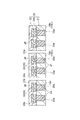
- FIG. 4 is a diagram for explaining the configuration of the torsion bar unit.
- each torsion bar portion 10 includes a plurality of straight portions 10a (in this embodiment, nine straight portions 10a 1 to 10a 9 ) and a plurality of folded portions 10b (in this embodiment). , Eight folded portions 10b 1 to 10b 8 ) and a pair of connection portions 10c and 10d.
- the straight portions 10a 1 to 10a 9 extend in the first direction along the swing axis L of the torsion bar portion 10, and are juxtaposed in the second direction intersecting the first direction.
- the folded portions 10b 1 to 10b 8 are provided to extend in the second direction. In the present embodiment, the first direction and the second direction are orthogonal to each other.
- one end of each of the straight portions 10a 1 and 10a 2 is connected to the folded portion 10b 1 .
- the folded portions 10b 1 to 10b 8 connect both ends of the straight portions 10a 2 to 10a 8 alternately.
- the folded portions 10b 1 , 10b 2 , 10b 7 and 10b 8 are straight, and the folded portions 10b 3 to 10b 6 are curved.
- Jikajo portion 10a 1 is connected to one end of the connecting portion 10d.
- the straight portion 10a 1 is one of the straight portions 10a 1 to 10a 9 that is located on the outermost side in the second direction.
- the other end of the connection portion 10d is coupled to the movable portion 8 at the connection location 11b. That is, the connection portion 10d is connected to the Jikajo portion 10a 1 and the movable portion 8.
- connection portion 10a 9 One end of the straight portion 10a 9 is connected to one end of the connection portion 10c.
- the straight portion 10a 9 is the other straight portion located on the outermost side in the second direction among the straight portions 10a 1 to 10a 9 .
- the other end of the connection portion 10d is coupled to the support portion 6 at the connection location 11a. That is, the connection portion 10 c is connected to the straight portion 10 a 9 and the support portion 6.
- the torsion bar portion 10 includes straight portions 10a 1 to 10a 9 , folded portions 10b 1 to 10b 8 , and connection portions 10c and 10d. Thereby, the torsion bar portion 10 has a meandering shape.
- the connection portions 11a and 11b are located on an imaginary line extending in the direction along the swing axis L. The imaginary line passes through the central portion of the torsion bar portion 10 in the second direction.
- FIG. 5 is a view for explaining a cross-sectional configuration along the line VV in FIG.
- FIG. 6 is a view for explaining a cross-sectional configuration along the line VI-VI in FIG.
- FIG. 7 is a view for explaining a cross-sectional configuration along the line VII-VII in FIG.
- FIG. 8 is a diagram for explaining a cross-sectional configuration along the line VIII-VIII in FIG.
- FIG. 9 is a diagram for explaining a cross-sectional configuration along the line IX-IX in FIG.
- FIG. 10 is a diagram for explaining a cross-sectional configuration along the line XX of FIG.
- the wiring 20 constitutes a portion of the lead conductors 16a, 16b, 18a, and 18b that is disposed on the corresponding torsion bar portion 10. That is, the lead conductors 16 a, 16 b, 18 a, 18 b include the wiring 20.
- the wiring 20 includes a wiring part 21, a wiring part 22, and a wiring part 23.
- the wiring portion 21 is disposed in the folded portion 10b (10b 1 to 10b 8 ).
- the wiring portion 22 is mainly disposed in the straight portion 10a (10a 1 to 10a 9 ).
- the wiring portion 23 is disposed in the connection portions 10c and 10d.
- the wiring part 23 arranged in the connection part 10c is configured similarly to the wiring part 23 arranged in the connection part 10d. For this reason, the cross-sectional configuration of the wiring portion 23 is illustrated only in the wiring portion 23 disposed in the connection portion 10d, and the cross-sectional configuration of the wiring portion 23 disposed in the connection portion 10c is not illustrated.
- the wiring portion 21 is arranged so as to be embedded in the groove 25a formed in the folded portion 10b as shown in FIGS.
- the wiring portion 21 is made of a first metal material made of Cu and is formed by a damascene method. That is, the wiring part 21 includes a damascene wiring part.
- the groove 25a is formed by etching the folded portion 10b.
- the thickness of the torsion bar portion 10 can be set to about 20 ⁇ m to 60 ⁇ m, for example.
- the depth of the groove 25a can be set to about 5 ⁇ m to 15 ⁇ m, for example.
- the wiring portion 22 is disposed on the straight portion 10a. Specifically, the wiring portion 22 is disposed in the insulating layer 26 disposed on one main surface of the torsion bar portion 10.
- the insulating layer 26 is configured to cover a part of the wiring portion 22.
- the insulating layer 26 is a thermal oxide film obtained by thermally oxidizing the torsion bar portion 10.
- the insulating layer 26 is made of, for example, silicon oxide (SiO 2 ).
- the thickness of the insulating layer can be set to about 0.5 ⁇ m, for example.
- the wiring portion 22 is made of a metal material that is less likely to be plastically deformed than Cu, which is the first metal material.
- the metal material constituting the wiring portion 22 is a metal material that is less likely to be plastically deformed than Cu, and is, for example, Al or an alloy containing Al.
- the alloy containing Al include an Al—Si alloy, an Al—Cu alloy, and an Al—Si—Cu alloy.
- the composition ratio of the Al—Si alloy can be, for example, 99% for Al and 1% for Si.
- the composition ratio of the Al—Cu alloy can be, for example, 99% for Al and 1% for Cu.
- the composition ratio of the Al—Si—Cu alloy can be, for example, 98% for Al, 1% for Si, and 1% for Cu.
- the wiring part 22 includes a part 22a located on the wiring part 21, as shown in FIGS.
- the portion 22a of the wiring portion 22 is disposed on the wiring portion 21 so as to cover the opening of the groove 25a.
- a portion 22 a of the wiring portion 22 is connected to the wiring portion 21.
- the wiring portion 21 arranged in the folded portion 10b is connected to the portion 22a of the wiring portion 22, and the wiring portion 23 arranged in the connection portion 10d is connected to the portion 22b of the wiring portion 22.
- the part 22 a of the wiring part 22 is connected to the wiring part 21.
- the wiring part 21 is a wiring formed by a damascene method.
- the wiring portion 22 is made of, for example, Al or an alloy containing Al.
- FIGS. 7 and 8 show locations in the wiring 20 where the wiring portion 22 disposed in the straight portion 10a and the wiring portion 21 disposed in the folded portion 10b are switched.
- the wiring portion 23 is disposed so as to be embedded in the groove 25b formed in the connecting portion 10d (10c) as shown in FIG.
- the wiring portion 23 is made of a first metal material made of Cu and is formed by a damascene method. That is, the wiring part 23 also includes a damascene wiring part.
- the groove 25b is formed by etching the connection portion 10d (10c). The depth of the groove 25b can be set to about 5 ⁇ m to 15 ⁇ m, for example.
- the wiring part 22 includes a part 22b located on the wiring part 23 as shown in FIG.
- the portion 22b of the wiring portion 22 is disposed on the wiring portion 23 so as to cover the opening of the groove 25b.
- a portion 22 b of the wiring portion 22 is connected to the wiring portion 23.
- the coil 16 when a current flows through the coil 16, Lorentz force is generated in a predetermined direction in the electrons flowing in the coil 16 due to the magnetic field generated by the magnetic field generator 4. For this reason, the coil 16 receives a force in a predetermined direction.
- the first movable portion 81 swings around the swing axis of the torsion bar portion 10. That is, the first movable portion 81 reciprocates around the rotation axis of the torsion bar portion 10.
- a Lorentz force is generated in a predetermined direction for electrons flowing in the coil 18 due to the magnetic field generated by the magnetic field generator 4.
- the coil 18 receives a force in a predetermined direction.
- the second movable portion 82 swings around the swing axis of the torsion bar portion 14. That is, the second movable portion 82 reciprocates around the rotation axis of the torsion bar portion 14. Therefore, the mirror arrangement portion 83 (mirror 3) can be oscillated around two orthogonal oscillation axes by controlling the direction and magnitude of the currents of the coil 16 and the coil 18, respectively.
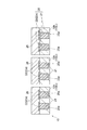
- FIG. 11 is a diagram for explaining a state of stress generated in the torsion bar portion 10.
- FIG. 11 shows the result of simulating the stress on the torsion bar portion 10 with the support portion 6 having a substantially rectangular parallelepiped shape and the movable portion 8 (first movable portion 81) having a substantially rectangular flat plate shape. It has been clarified that a large stress is applied to a portion displayed in black on the straight portion 10 a extending in the direction along the swing axis of the torsion bar portion 10.
- the wiring portion 22 arranged in the straight portion 10a is made of Al or an alloy containing Al. For this reason, even when a large stress acts on the straight portion 10a, plastic deformation of the wiring portion 22 is suppressed. Therefore, it is possible to suppress the wiring 20 arranged in the torsion bar portion 10 from inhibiting the swinging of the movable portion 8 (first movable portion 81).
- the wiring portion 21 arranged in the folded portion 10b is a damascene wiring portion made of Cu. For this reason, resistance reduction of the wiring 20 arrange
- not only the wiring part 21 but also the wiring part 23 arranged in the connection parts 10c and 10d is a damascene wiring part made of Cu. For this reason, even when the wiring 20 has the wiring part 23, it is suppressed that the resistance of wiring becomes high. As a result, the resistance of the wiring 20 can be reliably reduced. As shown in FIG. 11, a large stress is unlikely to act on the connection portions 10c and 10d. Therefore, even when the wiring portion 23 arranged in the connection portions 10c and 10d is a damascene wiring portion made of Cu, the possibility of hindering the swing of the movable portion 8 (first movable portion 81) is extremely low.
- the wiring parts 21 and 23 are damascene wiring parts as described above. For this reason, due to the process in the manufacturing process, the corner edge located on the surface side of the folded portion 10b and the connection portions 10c and 10d may be locally thinned to reduce the cross-sectional area. When the cross-sectional area of the wiring portions 21 and 23 decreases, the resistance of the entire wiring 20 increases. However, since the wiring part 22 includes the parts 22a and 22b arranged on the wiring parts 21 and 23, the resistance of the wiring 20 is prevented from increasing even when the wiring parts 21 and 23 are thinned. be able to.
- the above-described portions 22a and 22b are arranged so as to cover the openings of the grooves 25a and 25b. For this reason, Cu in the wiring portions 21 and 23 is difficult to diffuse into the insulating layer 26. As a result, occurrence of a short circuit between the metal materials (Cu in this embodiment) constituting the wiring portions 21 and 23 is suppressed.
- connection portions 11a and 11b are located on an imaginary line that extends in the first direction and passes through the central portion of the torsion bar portion 10 in the second direction.
- the resonance frequency of the torsion bar unit 10 is determined by the width of the torsion bar unit 10 and the length of the torsion bar unit 10 in the first direction.
- the straight portion 10a is not juxtaposed along the swing axis L, but is juxtaposed in the second direction intersecting the first direction. For this reason, even if the number of the straight portions 10a in the straight direction increases, the length of the torsion bar portion 10 in the first direction does not change. Therefore, the torsion bar unit 10 can be easily designed to set the resonance frequency of the torsion bar unit 10 to a desired value.
- the resistance value of the folded portion 10b is higher than the resistance value of the straight portion 10a due to its shape. For this reason, by arranging the wiring portion 21 formed by the damascene method in the folded portion 10b and arranging the wiring portion 22 in the straight portion 10a, it is possible to suppress an increase in the resistance of the torsion bar portion 10 as a whole. it can.
- the wiring portion 22 arranged in the straight portion 10a (the straight portions 10a 1 to 10a 9 ) is made of Al or an alloy containing Al, but is not limited thereto.
- the wiring portions 22 do not have to be arranged in all the straight portions 10 a.
- FIG. 12 is a diagram for explaining a modification of the configuration of the wiring, and corresponds to a cross-sectional configuration along the line VV in FIG.
- FIG. 13 is a diagram for explaining a modified example of the wiring configuration, and corresponds to a cross-sectional configuration along the line VI-VI in FIG.
- the wiring portions 21 formed by the damascene method are arranged in the straight portions 10 a 1 and 10 a 9 that are located on the outermost side in the second direction among the straight portions 10 a. May be.
- the stress acting on the straight portions 10a 1 and 10a 9 is smaller than that of the other straight portions (10a 2 to 10a 8 ).
- the wire portion 21 in Jikajo portion 10a 1, 10a 9, Jikajo portion 10a 1, 10a 9 to be the wiring portion 21 plastically deformed hardly occurs arrangement.
- the wiring portion 21 in the straight portions 10a 1 and 10a 9 the resistance of the wiring 20 can be further reduced.
- the wiring portion 21 may also be arranged in the straight portions 10a 2 and 10a 8 .
- the straight portions 10a 1 , 10a 2 , 10a 8 , and 10a 9 that are located outside in the second direction among the straight portions 10a are straight portions 10a 3 to 10a that are close to the swing axis L.
- the acting stress is small.
- the wiring portion 21 is arranged in the straight portions 10a 1 , 10a 2 , 10a 8 , 10a 9 , the wiring portions arranged in the straight portions 10a 1 , 10a 2 , 10a 8 , 10a 9 21 plastic deformation hardly occurs.
- the resistance of the wiring 20 can be further reduced.
- the folded portions 10b 1 , 10b 2 , 10b 7 , and 10b 8 have a straight shape, and the folded portions 10b 3 to 10b 6 have a curved shape, but are not limited thereto.
- the folded portion 10b may be all straight or all may be curved.
- the folded portion 10b may be a combination of a straight shape and a curved shape as appropriate, or may have a different shape.
- the torsion bar portion 10 has a meandering shape with nine straight portions 10a (10a 1 to 10a 9 ) and eight folded portions 10b (10b 1 to 10b 8 ).
- returning part 10b is not limited to this.
- the shape of the mirror 3 and the mirror arrangement portion 83 may be, for example, a polygonal shape or an elliptical shape.
- the actuator device 2 may be an actuator device that drives members other than the mirror 3.
- the torsion bar portion 10 has a meandering shape and the wiring 20 is disposed on the torsion bar portion 10, but the present invention is not limited to this.
- the torsion bar portions 10 and 14 may have a meandering shape and the wiring 20 may be disposed.
- Only the torsion bar portion 14 may have a meandering shape, and the wiring 20 may be disposed on the torsion bar portion 14.
- the torsion bar portion 10 has a meandering shape and the wiring 20 is disposed on the torsion bar portion 10.
- the stress applied to the torsion bar portion 14 is a stress applied when the second movable portion 82 swings.
- the stress applied to the torsion bar portion 10 is a stress applied when the first movable part 81 and the second movable part 82 are swung. That is, the stress applied to the torsion bar portion 14 is smaller than the stress applied to the torsion bar portion 10. For this reason, the torsion bar portion 14 is less susceptible to problems due to stress than the torsion bar portion 10. Therefore, the structure of the torsion bar portion 14 can be simplified, and the yield in manufacturing the actuator device 2 can be improved.
- the movable portion 8 is configured to be driven in the biaxial direction of the swing shaft of the torsion bar portion 10 and the swing shaft of the torsion bar portion 14, but is not limited thereto.
- the actuator device 2 may be configured to be driven by one coil disposed on the movable part.
- the actuator device 2 may be preferably configured such that a lead conductor is disposed in each of the pair of torsion bar portions. Since the lead conductor is disposed on the torsion bar portion, it is possible to know the breakage of the torsion bar portion from the presence or absence of the current flowing in the lead conductor.
- the actuator device 2 may adopt a configuration in which the operation of the actuator device is interrupted when damage is detected.
- the number of grooves formed in the torsion bar portion is smaller than when the lead conductor is disposed only in one of the pair of torsion bar portions. . For this reason, the stress applied to the torsion bar portion can be reduced. Furthermore, since there is only one wiring arranged in each torsion bar portion, a short circuit between the wirings can be prevented.
- the swinging (driving) of the movable portion 8 is performed by electromagnetic force, but is not limited thereto.
- the swinging (driving) of the movable part 8 may be performed by a piezoelectric element.
- the wiring 20 is used as a wiring for applying a voltage to the piezoelectric element.
Abstract
Provided is an actuator device in which a torsion bar section (10) has a serpentine shape that includes a plurality of straight sections (10a) and a plurality of curved sections (10b). The plurality of straight sections (10a) extend in a first direction that follows a rocker shaft (L) and are placed alongside a second direction that intersects the first direction. The plurality of curved sections (10b) are connected in an alternating manner to both ends of the plurality of straight sections (10a). Wiring is arranged on the torsion bar section (10). The wiring comprises a first wiring section and a second wiring section. The first wiring section is arranged so as to be embedded within a groove that is formed on the curved sections (10b) and comprises a damascene wiring section that is configured from a first metal material comprising Cu. The second wiring section is arranged on the straight sections (10a) and is configured from a second metal material that is less likely to plastically deform than the first metal material.
Description
本発明は、アクチュエータ装置と、ミラー駆動装置と、に関する。
The present invention relates to an actuator device and a mirror driving device.
支持部と、コイルが配置された可動部と、コイルに磁界を作用させる磁界発生部と、コイルに接続される配線が配置され、可動部を支持部に揺動可能に連結するトーションバー部と、を備えているアクチュエータ装置が知られている(例えば、特許文献1参照)。上記トーションバー部は、複数の直状部分と複数の折り返し部分とを有する蛇行形状を呈している。複数の直状部分は、トーションバー部の揺動軸に沿う第一方向に延び、第一方向と交差する第二方向に併置されている。複数の折り返し部分は、複数の直状部分の両端を交互に連結している。
A support part, a movable part in which the coil is arranged, a magnetic field generating part for applying a magnetic field to the coil, a wiring connected to the coil, and a torsion bar part for slidably coupling the movable part to the support part; Are known (see, for example, Patent Document 1). The torsion bar portion has a meandering shape having a plurality of straight portions and a plurality of folded portions. The plurality of straight portions extend in the first direction along the swing axis of the torsion bar portion, and are juxtaposed in the second direction intersecting the first direction. The plurality of folded portions alternately connect both ends of the plurality of straight portions.
本発明は、配線の低抵抗化を図り、且つ、配線が可動部の揺動を阻害するのを抑制することが可能なアクチュエータ装置及びミラー駆動装置を提供することを目的とする。
It is an object of the present invention to provide an actuator device and a mirror driving device that can reduce the resistance of the wiring and suppress the wiring from inhibiting the swing of the movable part.
本発明者らは、調査研究の結果、以下のような事実を新たに見出した。
The present inventors have newly found the following facts as a result of research.
トーションバー部が上述したような蛇行形状を呈している場合、トーションバー部に配置される配線は、各折り返し部分に配置される配線部分と、当該配線部分に接続されると共に各直状部分に配置される配線部分と、を有する。折り返し部分に配置される配線部分は、その形状に起因して、直状部分に配置される配線部分よりも抵抗が高い。このため、折り返し部分に配置される配線部分は、配線全体での抵抗が高い。配線の抵抗が高いと、当該配線が発熱すると共に、コイルに供給する電流量を十分に確保することが難しい。コイルへの電流量を十分に確保できない場合、可動部の揺動範囲が狭くなる。
When the torsion bar part has a meandering shape as described above, the wiring arranged in the torsion bar part is connected to the wiring part arranged in each folded part, the wiring part and the straight part. A wiring portion to be disposed. The wiring portion arranged in the folded portion has a higher resistance than the wiring portion arranged in the straight portion due to its shape. For this reason, the wiring part arrange | positioned at a folding | turning part has high resistance in the whole wiring. If the resistance of the wiring is high, the wiring generates heat and it is difficult to secure a sufficient amount of current to be supplied to the coil. When a sufficient amount of current to the coil cannot be secured, the swing range of the movable part becomes narrow.
配線が銅(Cu)からなるダマシン配線である構成を採用することにより、トーションバー部に配置される配線全体での抵抗を大幅に低くすることが可能である。しかしながら、配線がCuからなるダマシン配線である場合、配線が可動部の揺動を阻害するおそれがある。
By adopting a configuration in which the wiring is a damascene wiring made of copper (Cu), it is possible to significantly reduce the resistance of the entire wiring arranged in the torsion bar portion. However, when the wiring is a damascene wiring made of Cu, the wiring may hinder the swinging of the movable portion.
上述したような蛇行形状を呈しているトーションバー部では、可動部がトーションバー部の揺動軸周りに揺動すると、トーションバー部の揺動軸に沿う第一方向に延びる直状部分に大きな応力が作用する。このため、例えば、可動部がトーションバー部の揺動軸周りの一方向に揺動した場合、直状部分に位置する、Cuからなるダマシン配線に大きな応力が作用し、Cuからなるダマシン配線自体が塑性変形する。配線(ダマシン配線)が塑性変形した状態では、可動部が初期位置に戻らないおそれ、又は、可動部がトーションバー部の揺動軸周りの上記一方向とは反対方向に揺動する際に機械的な抵抗が生じるおそれがある。
In the torsion bar portion having the meandering shape as described above, when the movable portion swings around the swing shaft of the torsion bar portion, the straight portion extending in the first direction along the swing shaft of the torsion bar portion is large. Stress acts. For this reason, for example, when the movable portion swings in one direction around the swing axis of the torsion bar portion, a large stress acts on the damascene wiring made of Cu, which is located in the straight portion, and the damascene wiring made of Cu itself Is plastically deformed. When the wiring (damascene wiring) is plastically deformed, the movable part may not return to the initial position, or when the movable part swings in a direction opposite to the one direction around the swing axis of the torsion bar part. Resistance may occur.
本発明者らは、配線の低抵抗化を図り、且つ、配線が可動部の揺動を阻害するのを抑制し得る構成について鋭意研究を行った。
The inventors of the present invention have made extensive studies on a configuration that can reduce the resistance of the wiring and can suppress the wiring from inhibiting the swinging of the movable portion.
その結果、本発明者らは、直状部分に位置する配線部分の塑性変形を抑制し得る構成を想到するに至った。この構成では、大きな応力が作用する直状部分に配置される配線部分が、Cuからなるダマシン配線ではなく、Cuよりも塑性変形が生じ難い金属材料からなる配線である。
As a result, the present inventors have come up with a configuration that can suppress plastic deformation of the wiring portion located in the straight portion. In this configuration, the wiring portion arranged in the straight portion to which a large stress acts is not a damascene wiring made of Cu but a wiring made of a metal material that is less likely to undergo plastic deformation than Cu.
本発明者らは、折り返し部分に作用する応力は直状部分に比して低いことに着目した。本発明者らは、折り返し部分に配置される配線部分がCuからなるダマシン配線である構成の採用により、配線の低抵抗化を図り得ることを想到するに至った。折り返し部分に配置される配線部分は、上述したように、その形状に起因して、抵抗が比較的高い。このため、折り返し部分に配置される配線部分がCuからなるダマシン配線である場合、配線の抵抗を低く抑えることが可能である。
The inventors of the present invention noted that the stress acting on the folded portion is lower than that of the straight portion. The present inventors have conceived that the resistance of the wiring can be reduced by adopting a configuration in which the wiring portion arranged in the folded portion is a damascene wiring made of Cu. As described above, the wiring portion arranged in the folded portion has a relatively high resistance due to its shape. For this reason, when the wiring part arrange | positioned at a folding | turning part is damascene wiring which consists of Cu, it is possible to suppress resistance of wiring low.
本発明の一つの観点に係るアクチュエータ装置は、支持部と、導体が配置された可動部と、導体に接続される配線が配置され、可動部を支持部に揺動可能に連結するトーションバー部と、を備え、トーションバー部は、トーションバー部の揺動軸に沿う第一方向に延び、第一方向と交差する第二方向に併置される複数の直状部分と、複数の直状部分の両端を交互に連結する複数の折り返し部分と、を有する蛇行形状を呈しており、配線は、各折り返し部分に配置される第一配線部分と、第一配線部分に接続されると共に各直状部分に配置される第二配線部分と、を有し、第一配線部分は、折り返し部分に形成された溝内に埋め込まれるように配置され、Cuからなる第一金属材料によって構成されるダマシン配線部分を含み、第二配線部分は、直状部分上に配置され、第一金属材料よりも塑性変形し難い第二金属材料によって構成されている。
An actuator device according to an aspect of the present invention includes a torsion bar portion that includes a support portion, a movable portion on which a conductor is disposed, and a wiring connected to the conductor, and that swingably connects the movable portion to the support portion A torsion bar portion extending in a first direction along the swing axis of the torsion bar portion, and a plurality of straight portions juxtaposed in a second direction intersecting the first direction, and a plurality of straight portions A plurality of folded portions that alternately connect both ends of the wire, and a wiring is connected to the first wiring portion and the first wiring portion arranged in each folded portion, and each straight shape A damascene wiring having a second wiring portion disposed in the portion, the first wiring portion being disposed so as to be embedded in a groove formed in the folded portion, and configured by a first metal material made of Cu Part including the second wiring part , Disposed on Jikajo portion is constituted by a second metallic material difficult to plastically deform than the first metallic material.
本発明の一つの観点に係るアクチュエータ装置では、折り返し部分に配置される第一配線部分が、Cuからなる第一金属材料によって構成されるダマシン配線部分を含む。このため、トーションバー部に配置される配線の低抵抗化を図ることができる。直状部分に配置される第二配線部分が、第一金属材料よりも塑性変形し難い第二金属材料によって構成される。このため、直状部分に大きな応力が作用する場合でも、第二配線部分の塑性変形が抑制される。したがって、トーションバー部に配置される配線が可動部の揺動を阻害するのを抑制することができる。
In the actuator device according to one aspect of the present invention, the first wiring portion arranged in the folded portion includes a damascene wiring portion made of a first metal material made of Cu. For this reason, resistance reduction of the wiring arrange | positioned at a torsion bar part can be achieved. The 2nd wiring part arrange | positioned at a straight-shaped part is comprised with the 2nd metal material which is hard to carry out plastic deformation rather than a 1st metal material. For this reason, even when a large stress acts on the straight portion, the plastic deformation of the second wiring portion is suppressed. Therefore, it can suppress that the wiring arrange | positioned at a torsion bar part inhibits rocking | fluctuation of a movable part.
第一配線部分は、溝の開口を覆うようにダマシン配線部分上に配置され、第二金属材料によって構成される部分を更に含んでもよい。この場合、第一配線部分の抵抗を更に低くできる。
The first wiring portion may further include a portion that is disposed on the damascene wiring portion so as to cover the opening of the groove and is configured by the second metal material. In this case, the resistance of the first wiring portion can be further reduced.
ダマシン配線部分では、その製造過程での工程に起因して、折り返し部分の表面側に位置化する角縁が局所的に減肉されて、断面積が減少するおそれがある。ダマシン配線部分の断面積が減少すると、第一配線部分の抵抗が高くなる。しかしながら、第一配線部分が、溝の開口を覆うようにダマシン配線部分上に配置される部分を更に含んでいるため、ダマシン配線部分が減肉された場合でも、第一配線部分の抵抗が高くなるのを防ぐことができる。
In the damascene wiring portion, due to a process in the manufacturing process, the corner edge located on the surface side of the folded portion is locally thinned, and the cross-sectional area may be reduced. When the cross-sectional area of the damascene wiring portion decreases, the resistance of the first wiring portion increases. However, since the first wiring portion further includes a portion arranged on the damascene wiring portion so as to cover the opening of the groove, even when the damascene wiring portion is thinned, the resistance of the first wiring portion is high. Can be prevented.
トーションバー部と支持部との接続箇所及びトーションバー部と可動部との接続箇所は、トーションバー部の第二方向での中央部分を通り第一方向に延びる仮想線上に位置していてもよい。
The connection location between the torsion bar portion and the support portion and the connection location between the torsion bar portion and the movable portion may be located on a virtual line extending in the first direction through the central portion in the second direction of the torsion bar portion. .
トーションバー部の共振周波数は、トーションバー部の幅とトーションバー部の第一方向での長さで決まる。直状部分に作用する応力を小さくする構成として、直状部分の数を増やすことが考えられる。直状部分は、第一方向ではなく、第二方向に併置されている。このため、直状方向の数を増やした場合でも、トーションバー部の第一方向での長さは変わらない。したがって、トーションバー部の共振周波数を所望の値に設定するための、トーションバー部の設計が容易となる。
The resonance frequency of the torsion bar part is determined by the width of the torsion bar part and the length of the torsion bar part in the first direction. As a configuration for reducing the stress acting on the straight portion, it is conceivable to increase the number of straight portions. The straight portions are juxtaposed not in the first direction but in the second direction. For this reason, even when the number of straight directions is increased, the length of the torsion bar portion in the first direction does not change. Therefore, the torsion bar part can be easily designed to set the resonance frequency of the torsion bar part to a desired value.
トーションバー部は、複数の直状部分のうち第二方向で最も外側に位置する一方の直状部分と支持部とを接続する第一接続部分と、複数の直状部分のうち第二方向で最も外側に位置する他方の直状部分と可動部とを接続する第二接続部分と、を更に有し、配線は、第一配線部分に接続されると共に第一及び第二接続部分にそれぞれ配置される第三配線部分を更に有していてもよい。
The torsion bar portion includes a first connecting portion that connects one of the plurality of straight portions located on the outermost side in the second direction and the support portion, and a second portion of the plurality of straight portions in the second direction. And a second connection portion for connecting the other straight portion located on the outermost side and the movable portion, and the wiring is connected to the first wiring portion and arranged in the first and second connection portions, respectively. It may further have a third wiring portion.
第三配線部分は、第一及び第二接続部分にそれぞれ形成された溝内に埋め込まれるように配置され、第一金属材料によって構成されるダマシン配線部分を含んでもよい。この場合、配線が第三配線部分を有している場合でも、配線の抵抗が高くなるのが抑制される。この結果、配線の低抵抗化を確実に図ることができる。
The third wiring portion may include a damascene wiring portion that is disposed so as to be embedded in grooves formed in the first and second connection portions, respectively, and is configured of a first metal material. In this case, even when the wiring has the third wiring portion, the resistance of the wiring is suppressed from increasing. As a result, the resistance of the wiring can be reliably reduced.
第二金属材料は、Al又はAlを含む合金からなっていてもよい。この場合、第二配線部分の塑性変形を極めて良好に抑制することができる。
The second metal material may be made of Al or an alloy containing Al. In this case, the plastic deformation of the second wiring portion can be suppressed extremely well.
可動部は、トーションバー部が連結される第一部分と、トーションバー部の揺動軸に直交する方向に延びる揺動軸周りに揺動可能に第一部分に支持される第二部分と、を有していてもよい。この場合、可動部の第二部分を直交する二軸周りにそれぞれ揺動させることができる。
The movable part has a first part to which the torsion bar part is coupled, and a second part supported by the first part so as to be swingable about a swing axis extending in a direction perpendicular to the swing axis of the torsion bar part. You may do it. In this case, the second part of the movable part can be swung around two orthogonal axes.
可動部には、導体としてコイルが配置されており、コイルに磁界を作用させる磁界発生部を更に備えていてもよい。この場合、磁界が作用しているコイルに電流を流すことにより可動部を揺動させることができる。
The movable part may be further provided with a magnetic field generating part for arranging a coil as a conductor and applying a magnetic field to the coil. In this case, the movable part can be swung by passing a current through the coil on which the magnetic field acts.
本発明の一つの観点に係るミラー駆動装置は、ミラー駆動装置であって、上記アクチュエータ装置と、可動部に配置されるミラーと、を備える。
A mirror driving device according to one aspect of the present invention is a mirror driving device, and includes the actuator device and a mirror disposed on a movable portion.
本発明の一つの観点に係るミラー駆動装置では、上述したように、トーションバー部に配置される配線の低抵抗化を図ることができると共に、トーションバー部に配置される配線が可動部の揺動を阻害するのを抑制することができる。
In the mirror driving device according to one aspect of the present invention, as described above, it is possible to reduce the resistance of the wiring arranged in the torsion bar portion, and the wiring arranged in the torsion bar portion swings the movable portion. Inhibiting movement can be suppressed.
本発明の上記観点によれば、配線の低抵抗化を図り、且つ、配線が可動部の揺動を阻害するのを抑制することが可能なアクチュエータ装置及びミラー駆動装置を提供することができる。
According to the above aspect of the present invention, it is possible to provide an actuator device and a mirror driving device capable of reducing the resistance of the wiring and suppressing the wiring from inhibiting the swing of the movable portion.
以下、添付図面を参照して、本発明の実施形態について詳細に説明する。なお、説明において、同一要素又は同一機能を有する要素には、同一符号を用いることとし、重複する説明は省略する。
Hereinafter, embodiments of the present invention will be described in detail with reference to the accompanying drawings. In the description, the same reference numerals are used for the same elements or elements having the same function, and redundant description is omitted.
図1~図3を参照して、本実施形態に係るミラー駆動装置1の構成を説明する。図1は、本実施形態に係るミラー駆動装置を示す斜視図である。図2は、図1に示すミラー駆動装置の上面図である。図3は、図1に示すミラー駆動装置における回路を説明するための図である。
The configuration of the mirror driving device 1 according to this embodiment will be described with reference to FIGS. FIG. 1 is a perspective view showing a mirror driving device according to the present embodiment. FIG. 2 is a top view of the mirror driving device shown in FIG. FIG. 3 is a diagram for explaining a circuit in the mirror driving device shown in FIG.
図1~図3に示されるように、ミラー駆動装置1は、アクチュエータ装置2とミラー3と、を備える。アクチュエータ装置2は、磁界発生部4と、支持部6と、可動部8と、一対のトーションバー部10と、を備える。
As shown in FIG. 1 to FIG. 3, the mirror driving device 1 includes an actuator device 2 and a mirror 3. The actuator device 2 includes a magnetic field generation unit 4, a support unit 6, a movable unit 8, and a pair of torsion bar units 10.
ミラー3は、金属薄膜により構成された光反射膜である。ミラー3は、平面視で、円形状を呈している。ミラー3に用いられる金属材料は、例えばアルミ(Al)、金(Au)、又は銀(Ag)が挙げられる。
The mirror 3 is a light reflecting film composed of a metal thin film. The mirror 3 has a circular shape in plan view. Examples of the metal material used for the mirror 3 include aluminum (Al), gold (Au), and silver (Ag).
磁界発生部4は矩形状を呈する平板である。磁界発生部4は、一対の主面4a,4b(不図示)を有する。磁界発生部4は可動部8に磁界を作用させる。磁界発生部4での磁極の配列には、ハルバッハ配列が採用されている。磁界発生部4は、例えば永久磁石などにより構成される。
The magnetic field generator 4 is a flat plate having a rectangular shape. The magnetic field generator 4 has a pair of main surfaces 4a and 4b (not shown). The magnetic field generator 4 applies a magnetic field to the movable part 8. A Halbach array is adopted as the magnetic pole array in the magnetic field generator 4. The magnetic field generation unit 4 is configured by, for example, a permanent magnet.
支持部6は、外側輪郭が矩形状を呈する枠体である。支持部6は、磁界発生部4上に、主面4aに対向するように配置されている。支持部6は、一対のトーションバー部10を介して可動部8を支持する。可動部8は、支持部6の内側に位置している。可動部8は、第一可動部分81と、第二可動部分82と、ミラー配置部分83と、を有している。本実施形態では、支持部6、可動部8、及びトーションバー部10は、一体に形成されており、例えばシリコン(Si)からなる。
The support part 6 is a frame body whose outer contour has a rectangular shape. The support 6 is disposed on the magnetic field generator 4 so as to face the main surface 4a. The support portion 6 supports the movable portion 8 via a pair of torsion bar portions 10. The movable part 8 is located inside the support part 6. The movable part 8 has a first movable part 81, a second movable part 82, and a mirror arrangement part 83. In this embodiment, the support part 6, the movable part 8, and the torsion bar part 10 are integrally formed, and are made of, for example, silicon (Si).
第一可動部分81は、支持部6の内側に位置すると共に、外側輪郭が矩形状を呈する平板状の枠体である。第一可動部分81は、トーションバー部10が連結され、支持部6と離間して配置されている。第一可動部分81は、一対のトーションバー部10を介して支持部6に揺動可能に支持されている。すなわち、第一可動部分81は、一対のトーションバー部10を介して支持部6に往復回転可能に支持されている。各トーションバー部10は、第一可動部分81を支持部6に揺動可能に連結している。第一可動部分81は、磁界発生部4と対向する主面と、当該主面の裏面である主面81aを有する。各トーションバー部10は、後述するように、蛇行形状を呈している。
The first movable portion 81 is a flat frame body that is located inside the support portion 6 and has a rectangular outer contour. The first movable portion 81 is connected to the torsion bar portion 10 and is spaced apart from the support portion 6. The first movable portion 81 is swingably supported by the support portion 6 via a pair of torsion bar portions 10. That is, the first movable portion 81 is supported by the support portion 6 via the pair of torsion bar portions 10 so as to be capable of reciprocating rotation. Each torsion bar portion 10 connects the first movable portion 81 to the support portion 6 in a swingable manner. The first movable portion 81 has a main surface that faces the magnetic field generator 4 and a main surface 81a that is the back surface of the main surface. Each torsion bar portion 10 has a meandering shape as described later.
第二可動部分82は、第一可動部分81の内側に位置すると共に、外側輪郭が矩形状を呈する平板状の枠体である。第二可動部分82は、第一可動部分81と離間して配置されている。第二可動部分82は、一対のトーションバー部14を介して第一可動部分81に揺動可能に支持されている。すなわち、第二可動部分82は、一対のトーションバー部14を介して第一可動部分81に往復回転可能に支持されている。各トーションバー部14は、第二可動部分82を第一可動部分81に揺動可能に連結している。第二可動部分82も、第一可動部分81と同様に、磁界発生部4と対向する主面と、当該主面の裏面である主面82aを有する。各トーションバー部14は、直状とされ、同一直線状に位置している。本実施形態では、トーションバー部14も、支持部6、可動部8、及びトーションバー部10と一体に形成されており、例えばSiからなる。
The second movable part 82 is a flat frame body that is located inside the first movable part 81 and has an outer contour that is rectangular. The second movable part 82 is disposed away from the first movable part 81. The second movable portion 82 is swingably supported by the first movable portion 81 via the pair of torsion bar portions 14. That is, the second movable portion 82 is supported by the first movable portion 81 through the pair of torsion bar portions 14 so as to be capable of reciprocating rotation. Each torsion bar portion 14 connects the second movable portion 82 to the first movable portion 81 so as to be swingable. Similarly to the first movable portion 81, the second movable portion 82 also has a main surface that faces the magnetic field generation unit 4 and a main surface 82a that is the back surface of the main surface. Each torsion bar portion 14 has a straight shape and is located on the same straight line. In the present embodiment, the torsion bar portion 14 is also formed integrally with the support portion 6, the movable portion 8, and the torsion bar portion 10, and is made of, for example, Si.
トーションバー部10の揺動軸はトーションバー部14の揺動軸と交差している。本実施形態においては、トーションバー部10の揺動軸は、トーションバー部14の揺動軸と直交している。すなわち、トーションバー部10の回転軸はトーションバー部14の回転軸と交差している。第二可動部分82は、トーションバー部10の揺動軸に直交する方向に延びる揺動軸周りに揺動可能に、第一可動部分81に支持されている。
The rocking axis of the torsion bar unit 10 intersects the rocking axis of the torsion bar unit 14. In the present embodiment, the swing axis of the torsion bar unit 10 is orthogonal to the swing axis of the torsion bar unit 14. That is, the rotation axis of the torsion bar unit 10 intersects with the rotation axis of the torsion bar unit 14. The second movable portion 82 is supported by the first movable portion 81 so as to be swingable around a swing shaft extending in a direction orthogonal to the swing shaft of the torsion bar portion 10.
ミラー配置部分83は、第二可動部分82の内側に位置すると共に、円形状を呈している。ミラー配置部分83は、第二可動部分82と一体化されており、第二可動部分82と一体的に揺動する。ミラー配置部分83は、磁界発生部4と対向する主面と、当該主面の裏面である主面83aと、を有する。ミラー3は、ミラー配置部分83の主面83a上に配置されている。
The mirror arrangement portion 83 is located inside the second movable portion 82 and has a circular shape. The mirror arrangement portion 83 is integrated with the second movable portion 82 and swings integrally with the second movable portion 82. The mirror arrangement portion 83 has a main surface that faces the magnetic field generator 4 and a main surface 83a that is the back surface of the main surface. The mirror 3 is arranged on the main surface 83 a of the mirror arrangement portion 83.
アクチュエータ装置2(ミラー駆動装置1)は、図3にも示されるように、第一可動部分81に配置されるコイル16と、第二可動部分82に配置されるコイル18と、を備えている。コイル16は、第一可動部分81の主面81a側に配置されている。コイル18は、第二可動部分82の主面82a側に配置されている。本実施形態では、第一可動部分81に配置される導体としてコイル16が用いられ、第二可動部分82に配置される導体としてコイル18が用いられている。
As shown in FIG. 3, the actuator device 2 (mirror drive device 1) includes a coil 16 disposed in the first movable portion 81 and a coil 18 disposed in the second movable portion 82. . The coil 16 is disposed on the main surface 81 a side of the first movable part 81. The coil 18 is disposed on the main surface 82 a side of the second movable portion 82. In the present embodiment, the coil 16 is used as a conductor arranged in the first movable part 81, and the coil 18 is used as a conductor arranged in the second movable part 82.
コイル16は、主面81aに直交する方向から見て、スパイラル状に複数周回巻回されている。コイル16の一端はコイル16の外側に位置し、コイル16の他端はコイル16の内側に位置する。コイル16の外側端部には、引き出し導体16aの一端が電気的に接続されている。コイル16の内側端部には、引き出し導体16bの一端が電気的に接続されている。
The coil 16 is wound in a plurality of rounds in a spiral shape when viewed from the direction orthogonal to the main surface 81a. One end of the coil 16 is located outside the coil 16, and the other end of the coil 16 is located inside the coil 16. One end of a lead conductor 16 a is electrically connected to the outer end portion of the coil 16. One end of the lead conductor 16 b is electrically connected to the inner end of the coil 16.
引き出し導体16a,16bは、主に一方のトーションバー部10上に配置され、第一可動部分81から支持部6に至っている。引き出し導体16a,16bの他端は、支持部6の表面に配置された電極17a,17bに電気的に接続されている。電極17a,17bは、図示しない制御回路などに電気的に接続されている。引き出し導体16aは、コイル16の上方を通るようにコイル16と立体的に交差している。
The lead conductors 16 a and 16 b are mainly disposed on one torsion bar portion 10 and reach the support portion 6 from the first movable portion 81. The other ends of the lead conductors 16 a and 16 b are electrically connected to electrodes 17 a and 17 b arranged on the surface of the support portion 6. The electrodes 17a and 17b are electrically connected to a control circuit (not shown). The lead conductor 16a crosses the coil 16 three-dimensionally so as to pass above the coil 16.
コイル18は、主面82aに直交する方向から見て、スパイラル状に複数周回巻回されている。コイル18の一端はコイル18の外側に位置し、コイル18の他端はコイル18の内側に位置する。コイル18の外側端部には、引き出し導体18aの一端が電気的に接続されている。コイル18の内側端部には、引き出し導体18bの一端が電気的に接続されている。
The coil 18 is wound a plurality of times in a spiral shape when viewed from the direction orthogonal to the main surface 82a. One end of the coil 18 is located outside the coil 18, and the other end of the coil 18 is located inside the coil 18. One end of the lead conductor 18 a is electrically connected to the outer end of the coil 18. One end of the lead conductor 18 b is electrically connected to the inner end of the coil 18.
引き出し導体18a,18bは、主にトーションバー部14上、第一可動部分81上、及び一方のトーションバー部10上に配置され、第二可動部分82から他方のトーションバー部10に至っている。引き出し導体18a,18bの他端は、支持部6の表面に配置された電極19a,19bに電気的に接続されている。電極19a,19bは、上記の図示しない制御回路などに電気的に接続されている。引き出し導体18a,18bは、コイル16の上方を通るようにコイル16と立体的に交差している。
The lead conductors 18a and 18b are mainly disposed on the torsion bar portion 14, the first movable portion 81, and the one torsion bar portion 10, and extend from the second movable portion 82 to the other torsion bar portion 10. The other ends of the lead conductors 18 a and 18 b are electrically connected to electrodes 19 a and 19 b disposed on the surface of the support portion 6. The electrodes 19a and 19b are electrically connected to the control circuit (not shown) and the like. The lead conductors 18 a and 18 b intersect the coil 16 three-dimensionally so as to pass over the coil 16.
ここで、図4を参照して、各トーションバー部10の構成について説明する。図4は、トーションバー部の構成を説明するための図である。
Here, the configuration of each torsion bar unit 10 will be described with reference to FIG. FIG. 4 is a diagram for explaining the configuration of the torsion bar unit.
図4に示されるように、各トーションバー部10は、複数の直状部分10a(本実施形態では、九つの直状部分10a1~10a9)と、複数の折り返し部分10b(本実施形態では、八つの折り返し部分10b1~10b8)と、一対の接続部分10c,10dを有している。直状部分10a1~10a9は、トーションバー部10の揺動軸Lに沿う第一方向に延びており、第一方向と交差する第二方向に併置されている。折り返し部分10b1~10b8は、第二方向に延びて設けられている。本実施形態では、第一方向と第二方向とが直交している。
As shown in FIG. 4, each torsion bar portion 10 includes a plurality of straight portions 10a (in this embodiment, nine straight portions 10a 1 to 10a 9 ) and a plurality of folded portions 10b (in this embodiment). , Eight folded portions 10b 1 to 10b 8 ) and a pair of connection portions 10c and 10d. The straight portions 10a 1 to 10a 9 extend in the first direction along the swing axis L of the torsion bar portion 10, and are juxtaposed in the second direction intersecting the first direction. The folded portions 10b 1 to 10b 8 are provided to extend in the second direction. In the present embodiment, the first direction and the second direction are orthogonal to each other.
折り返し部分10b1~10b8は、直状部分10a1~10a9のうち、第二方向で隣り合う二つの直状部分10a1~10a9の端同士を連結している。例えば、直状部分10a1,10a2それぞれ一方の端は、折り返し部分10b1に連結されている。このように、折り返し部分10b1~10b8は、直状部分10a2~10a8の両端を交互に連結している。本実施形態では、折り返し部分10b1,10b2,10b7,10b8は直状であり、折り返し部分10b3~10b6は湾曲している。
Folded portions 10b 1 ~ 10b 8 among the Jikajo portion 10a 1 ~ 10a 9, connects the end between the second two straight portions 10a adjacent in the direction 1 ~ 10a 9. For example, one end of each of the straight portions 10a 1 and 10a 2 is connected to the folded portion 10b 1 . In this way, the folded portions 10b 1 to 10b 8 connect both ends of the straight portions 10a 2 to 10a 8 alternately. In the present embodiment, the folded portions 10b 1 , 10b 2 , 10b 7 and 10b 8 are straight, and the folded portions 10b 3 to 10b 6 are curved.
直状部分10a1の他方の端は、接続部分10dの一方の端に連結されている。直状部分10a1は、直状部分10a1~10a9のうち第二方向で最も外側に位置する一方の直状部分である。接続部分10dの他方の端は、接続箇所11bにおいて可動部8に連結されている。すなわち、接続部分10dは、直状部分10a1と可動部8とに接続されている。
The other end of Jikajo portion 10a 1 is connected to one end of the connecting portion 10d. The straight portion 10a 1 is one of the straight portions 10a 1 to 10a 9 that is located on the outermost side in the second direction. The other end of the connection portion 10d is coupled to the movable portion 8 at the connection location 11b. That is, the connection portion 10d is connected to the Jikajo portion 10a 1 and the movable portion 8.
直状部分10a9の一方の端は、接続部分10cの一方の端に連結されている。直状部分10a9は、直状部分10a1~10a9のうち第二方向で最も外側に位置する他方の直状部分である。接続部分10dの他方の端は、接続箇所11aにおいて支持部6に連結されている。すなわち、接続部分10cは、直状部分10a9と支持部6とに接続されている。
One end of the straight portion 10a 9 is connected to one end of the connection portion 10c. The straight portion 10a 9 is the other straight portion located on the outermost side in the second direction among the straight portions 10a 1 to 10a 9 . The other end of the connection portion 10d is coupled to the support portion 6 at the connection location 11a. That is, the connection portion 10 c is connected to the straight portion 10 a 9 and the support portion 6.
トーションバー部10は、直状部分10a1~10a9、折り返し部分10b1~10b8、及び接続部分10c、10dを有している。これにより、トーションバー部10は蛇行形状を呈している。接続箇所11a,11bは、揺動軸Lに沿う方向に延びる仮想線上に位置している。仮想線は、トーションバー部10の第二方向での中央部分を通っている。
The torsion bar portion 10 includes straight portions 10a 1 to 10a 9 , folded portions 10b 1 to 10b 8 , and connection portions 10c and 10d. Thereby, the torsion bar portion 10 has a meandering shape. The connection portions 11a and 11b are located on an imaginary line extending in the direction along the swing axis L. The imaginary line passes through the central portion of the torsion bar portion 10 in the second direction.
次に、図5~図10を参照して、トーションバー部10に配置された配線20について説明する。図5は、図4のV-V線に沿った断面構成を説明するための図である。図6は、図4のVI-VI線に沿った断面構成を説明するための図である。図7は、図4のVII-VII線に沿った断面構成を説明するための図である。図8は、図4のVIII-VIII線に沿った断面構成を説明するための図である。図9は、図4のIX-IX線に沿った断面構成を説明するための図である。図10は、図4のX-X線に沿った断面構成を説明するための図である。
Next, the wiring 20 arranged in the torsion bar unit 10 will be described with reference to FIGS. FIG. 5 is a view for explaining a cross-sectional configuration along the line VV in FIG. FIG. 6 is a view for explaining a cross-sectional configuration along the line VI-VI in FIG. FIG. 7 is a view for explaining a cross-sectional configuration along the line VII-VII in FIG. FIG. 8 is a diagram for explaining a cross-sectional configuration along the line VIII-VIII in FIG. FIG. 9 is a diagram for explaining a cross-sectional configuration along the line IX-IX in FIG. FIG. 10 is a diagram for explaining a cross-sectional configuration along the line XX of FIG.
配線20は、引き出し導体16a,16b,18a,18bのうち、対応するトーションバー部10に配置された部分を構成している。すなわち、引き出し導体16a,16b,18a,18bは、配線20を含んでいる。配線20は、配線部分21、配線部分22、及び配線部分23を有している。配線部分21は、折り返し部分10b(10b1~10b8)に配置されている。配線部分22は、主に直状部分10a(10a1~10a9)に配置されている。配線部分23は、接続部分10c,10dに配置されている。接続部分10cに配置される配線部分23は、接続部分10dに配置される配線部分23と同様に構成されている。このため、配線部分23の断面構成の図示は、接続部分10dに配置される配線部分23のみとし、接続部分10cに配置される配線部分23の断面構成の図示を省略する。
The wiring 20 constitutes a portion of the lead conductors 16a, 16b, 18a, and 18b that is disposed on the corresponding torsion bar portion 10. That is, the lead conductors 16 a, 16 b, 18 a, 18 b include the wiring 20. The wiring 20 includes a wiring part 21, a wiring part 22, and a wiring part 23. The wiring portion 21 is disposed in the folded portion 10b (10b 1 to 10b 8 ). The wiring portion 22 is mainly disposed in the straight portion 10a (10a 1 to 10a 9 ). The wiring portion 23 is disposed in the connection portions 10c and 10d. The wiring part 23 arranged in the connection part 10c is configured similarly to the wiring part 23 arranged in the connection part 10d. For this reason, the cross-sectional configuration of the wiring portion 23 is illustrated only in the wiring portion 23 disposed in the connection portion 10d, and the cross-sectional configuration of the wiring portion 23 disposed in the connection portion 10c is not illustrated.
配線部分21は、図7~図9にも示されるように、折り返し部分10bに形成された溝25a内に埋め込まれるように配置されている。配線部分21は、Cuからなる第一金属材料によって構成され、ダマシン法により形成される。すなわち、配線部分21は、ダマシン配線部分を含んでいる。溝25aは、折り返し部分10bをエッチングすることにより形成される。トーションバー部10の厚さは、例えば、20μm~60μm程度に設定することができる。溝25aの深さは、例えば5μm~15μm程度に設定することができる。
The wiring portion 21 is arranged so as to be embedded in the groove 25a formed in the folded portion 10b as shown in FIGS. The wiring portion 21 is made of a first metal material made of Cu and is formed by a damascene method. That is, the wiring part 21 includes a damascene wiring part. The groove 25a is formed by etching the folded portion 10b. The thickness of the torsion bar portion 10 can be set to about 20 μm to 60 μm, for example. The depth of the groove 25a can be set to about 5 μm to 15 μm, for example.
配線部分22は、図5及び図6に示されるように、直状部分10a上に配置される。具体的には、配線部分22は、トーションバー部10の一方の主面上に配置された絶縁層26内に配置されている。絶縁層26は、配線部分22の一部を覆うように構成されている。絶縁層26は、トーションバー部10を熱酸化して得られる熱酸化膜である。絶縁層26は、例えば酸化シリコン(SiO2)からなる。絶縁層の厚さは、例えば0.5μm程度に設定することができる。
As shown in FIGS. 5 and 6, the wiring portion 22 is disposed on the straight portion 10a. Specifically, the wiring portion 22 is disposed in the insulating layer 26 disposed on one main surface of the torsion bar portion 10. The insulating layer 26 is configured to cover a part of the wiring portion 22. The insulating layer 26 is a thermal oxide film obtained by thermally oxidizing the torsion bar portion 10. The insulating layer 26 is made of, for example, silicon oxide (SiO 2 ). The thickness of the insulating layer can be set to about 0.5 μm, for example.
配線部分22は、第一金属材料であるCuよりも塑性変形し難い金属材料によって構成されている。配線部分22を構成する金属材料は、Cuよりも塑性変形し難い金属材料であり、例えば、Al又はAlを含む合金である。Alを含む合金としては、Al-Si合金、Al-Cu合金、又はAl-Si-Cu合金が挙げられる。Al-Si合金の組成比は、例えばAlが99%、Siが1%とすることができる。Al-Cu合金の組成比は、例えばAlが99%、Cuが1%とすることができる。Al-Si-Cu合金の組成比は、例えばAlが98%、Siが1%、Cuが1%とすることができる。配線部分22を構成する金属材料として上述した金属材料を採用することにより、配線部分22の塑性変形が極めて良好に抑制される。
The wiring portion 22 is made of a metal material that is less likely to be plastically deformed than Cu, which is the first metal material. The metal material constituting the wiring portion 22 is a metal material that is less likely to be plastically deformed than Cu, and is, for example, Al or an alloy containing Al. Examples of the alloy containing Al include an Al—Si alloy, an Al—Cu alloy, and an Al—Si—Cu alloy. The composition ratio of the Al—Si alloy can be, for example, 99% for Al and 1% for Si. The composition ratio of the Al—Cu alloy can be, for example, 99% for Al and 1% for Cu. The composition ratio of the Al—Si—Cu alloy can be, for example, 98% for Al, 1% for Si, and 1% for Cu. By adopting the above-described metal material as the metal material constituting the wiring portion 22, plastic deformation of the wiring portion 22 is suppressed extremely well.
配線部分22は、図7~図9に示されるように、配線部分21上に位置する部分22aを含んでいる。配線部分22の部分22aは、溝25aの開口を覆うように配線部分21上に配置されている。配線部分22の部分22aは、配線部分21と接続されている。
The wiring part 22 includes a part 22a located on the wiring part 21, as shown in FIGS. The portion 22a of the wiring portion 22 is disposed on the wiring portion 21 so as to cover the opening of the groove 25a. A portion 22 a of the wiring portion 22 is connected to the wiring portion 21.
図7に示されるように、折り返し部分10bに配置される配線部分21は配線部分22の部分22aと接続されており、接続部分10dに配置される配線部分23は配線部分22の部分22bと接続されている。図8に示されるように、直状部分10a1に配置される配線部分22では、配線部分22の部分22aが配線部分21と接続されている。配線部分21は、ダマシン法により形成された配線である。配線部分22は、例えば、Al又はAlを含む合金からなる。図7及び図8には、配線20において、直状部分10aに配置される配線部分22と折り返し部分10bに配置される配線部分21とが切り替えられる箇所が示されている。
As shown in FIG. 7, the wiring portion 21 arranged in the folded portion 10b is connected to the portion 22a of the wiring portion 22, and the wiring portion 23 arranged in the connection portion 10d is connected to the portion 22b of the wiring portion 22. Has been. As shown in FIG. 8, in the wiring part 22 arranged in the straight part 10 a 1 , the part 22 a of the wiring part 22 is connected to the wiring part 21. The wiring part 21 is a wiring formed by a damascene method. The wiring portion 22 is made of, for example, Al or an alloy containing Al. FIGS. 7 and 8 show locations in the wiring 20 where the wiring portion 22 disposed in the straight portion 10a and the wiring portion 21 disposed in the folded portion 10b are switched.
配線部分23は、図10にも示されるように、接続部分10d(10c)に形成された溝25b内に埋め込まれるように配置されている。配線部分23は、Cuからなる第一金属材料によって構成され、ダマシン法により形成される。すなわち、配線部分23も、ダマシン配線部分を含んでいる。溝25bは、接続部分10d(10c)をエッチングすることにより形成される。溝25bの深さは、例えば5μm~15μm程度に設定することができる。
The wiring portion 23 is disposed so as to be embedded in the groove 25b formed in the connecting portion 10d (10c) as shown in FIG. The wiring portion 23 is made of a first metal material made of Cu and is formed by a damascene method. That is, the wiring part 23 also includes a damascene wiring part. The groove 25b is formed by etching the connection portion 10d (10c). The depth of the groove 25b can be set to about 5 μm to 15 μm, for example.
配線部分22は、図10に示されるように、配線部分23上に位置する部分22bを含んでいる。配線部分22の部分22bは、溝25bの開口を覆うように配線部分23上に配置されている。配線部分22の部分22bは、配線部分23と接続されている。
The wiring part 22 includes a part 22b located on the wiring part 23 as shown in FIG. The portion 22b of the wiring portion 22 is disposed on the wiring portion 23 so as to cover the opening of the groove 25b. A portion 22 b of the wiring portion 22 is connected to the wiring portion 23.
本実施形態では、コイル16に電流が流れると、磁界発生部4によって生じる磁界により、コイル16内を流れる電子には所定の方向にローレンツ力が生じる。このため、コイル16は所定の方向に力を受ける。コイル16に流れる電流の向きや大きさなどを制御することにより、第一可動部分81が、トーションバー部10の揺動軸周りに揺動する。すなわち、第一可動部分81は、トーションバー部10の回転軸周りに往復回転する。コイル18に電流が流れると、磁界発生部4によって生じる磁界により、コイル18内を流れる電子には所定の方向にローレンツ力が生じる。このため、コイル18は所定の方向に力を受ける。コイル18に流れる電流の向きや大きさなどを制御することにより、第二可動部分82が、トーションバー部14の揺動軸周りに揺動する。すなわち、第二可動部分82は、トーションバー部14の回転軸周りに往復回転する。よって、コイル16及びコイル18の電流の向きや大きさなどをそれぞれ制御することにより、ミラー配置部分83(ミラー3)を直交する二つの揺動軸周りにそれぞれ揺動させることができる。
In the present embodiment, when a current flows through the coil 16, Lorentz force is generated in a predetermined direction in the electrons flowing in the coil 16 due to the magnetic field generated by the magnetic field generator 4. For this reason, the coil 16 receives a force in a predetermined direction. By controlling the direction and magnitude of the current flowing in the coil 16, the first movable portion 81 swings around the swing axis of the torsion bar portion 10. That is, the first movable portion 81 reciprocates around the rotation axis of the torsion bar portion 10. When a current flows through the coil 18, a Lorentz force is generated in a predetermined direction for electrons flowing in the coil 18 due to the magnetic field generated by the magnetic field generator 4. For this reason, the coil 18 receives a force in a predetermined direction. By controlling the direction and magnitude of the current flowing in the coil 18, the second movable portion 82 swings around the swing axis of the torsion bar portion 14. That is, the second movable portion 82 reciprocates around the rotation axis of the torsion bar portion 14. Therefore, the mirror arrangement portion 83 (mirror 3) can be oscillated around two orthogonal oscillation axes by controlling the direction and magnitude of the currents of the coil 16 and the coil 18, respectively.
ところで、図11に示されるように、可動部8(第一可動部分81)がトーションバー部10の揺動軸周りに揺動すると、トーションバー部10には、トーションバー部10の揺動軸に沿う方向に延びる直状部分10aに大きな応力が作用する。図11は、トーションバー部10に生じる応力の状態を説明するための図である。図11には、支持部6を略直方体状とし且つ可動部8(第一可動部分81)を略矩形平板状として、トーションバー部10に係る応力をシミュレーションした結果が示されている。トーションバー部10の揺動軸に沿う方向に延びる直状部分10aには、黒色で表示された箇所に大きな応力が作用していることが明らかとなった。
By the way, as shown in FIG. 11, when the movable portion 8 (first movable portion 81) swings around the swing axis of the torsion bar portion 10, the torsion bar portion 10 includes the swing shaft of the torsion bar portion 10. A large stress acts on the straight portion 10a extending in the direction along the line. FIG. 11 is a diagram for explaining a state of stress generated in the torsion bar portion 10. FIG. 11 shows the result of simulating the stress on the torsion bar portion 10 with the support portion 6 having a substantially rectangular parallelepiped shape and the movable portion 8 (first movable portion 81) having a substantially rectangular flat plate shape. It has been clarified that a large stress is applied to a portion displayed in black on the straight portion 10 a extending in the direction along the swing axis of the torsion bar portion 10.
本実施形態では、直状部分10aに配置される配線部分22が、Al又はAlを含む合金によって構成されている。このため、直状部分10aに大きな応力が作用する場合でも、配線部分22の塑性変形が抑制される。したがって、トーションバー部10に配置される配線20が可動部8(第一可動部分81)の揺動を阻害するのを抑制することができる。
In the present embodiment, the wiring portion 22 arranged in the straight portion 10a is made of Al or an alloy containing Al. For this reason, even when a large stress acts on the straight portion 10a, plastic deformation of the wiring portion 22 is suppressed. Therefore, it is possible to suppress the wiring 20 arranged in the torsion bar portion 10 from inhibiting the swinging of the movable portion 8 (first movable portion 81).
本実施形態では、折り返し部分10bに配置される配線部分21が、Cuからなるダマシン配線部分とされている。このため、トーションバー部10に配置される配線20の低抵抗化を図ることができる。
In the present embodiment, the wiring portion 21 arranged in the folded portion 10b is a damascene wiring portion made of Cu. For this reason, resistance reduction of the wiring 20 arrange | positioned at the torsion bar part 10 can be achieved.
本実施形態では、配線部分21だけでなく、接続部分10c,10dに配置される配線部分23も、Cuからなるダマシン配線部分とされている。このため、配線20が配線部分23を有している場合でも、配線の抵抗が高くなるのが抑制される。この結果、配線20の低抵抗化を確実に図ることができる。接続部分10c,10dには、図11に示されるように、大きな応力が作用し難い。したがって、接続部分10c,10dに配置される配線部分23がCuからなるダマシン配線部分である場合でも、可動部8(第一可動部分81)の揺動を阻害する可能性は極めて低い。
In this embodiment, not only the wiring part 21 but also the wiring part 23 arranged in the connection parts 10c and 10d is a damascene wiring part made of Cu. For this reason, even when the wiring 20 has the wiring part 23, it is suppressed that the resistance of wiring becomes high. As a result, the resistance of the wiring 20 can be reliably reduced. As shown in FIG. 11, a large stress is unlikely to act on the connection portions 10c and 10d. Therefore, even when the wiring portion 23 arranged in the connection portions 10c and 10d is a damascene wiring portion made of Cu, the possibility of hindering the swing of the movable portion 8 (first movable portion 81) is extremely low.
配線部分21,23は、上述したようにダマシン配線部分である。このため、製造過程での工程に起因して、折り返し部分10b及び接続部分10c,10dの表面側に位置化する角縁が局所的に減肉されて、断面積が減少する懼れがある。配線部分21,23の断面積が減少すると、配線20全体での抵抗が高くなる。しかしながら、配線部分22が、配線部分21,23上に配置された部分22a,22bを含んでいるため、配線部分21,23が減肉された場合でも、配線20の抵抗が高くなるのを防ぐことができる。
The wiring parts 21 and 23 are damascene wiring parts as described above. For this reason, due to the process in the manufacturing process, the corner edge located on the surface side of the folded portion 10b and the connection portions 10c and 10d may be locally thinned to reduce the cross-sectional area. When the cross-sectional area of the wiring portions 21 and 23 decreases, the resistance of the entire wiring 20 increases. However, since the wiring part 22 includes the parts 22a and 22b arranged on the wiring parts 21 and 23, the resistance of the wiring 20 is prevented from increasing even when the wiring parts 21 and 23 are thinned. be able to.
本実施形態では、溝25a,25bの開口を覆うように上述した部分22a,22bが配置されている。このため、配線部分21,23のCuが絶縁層26に拡散し難い。これにより、配線部分21,23を構成する金属材料(本実施形態でCu)の間でのショートの発生が抑制される。
In the present embodiment, the above-described portions 22a and 22b are arranged so as to cover the openings of the grooves 25a and 25b. For this reason, Cu in the wiring portions 21 and 23 is difficult to diffuse into the insulating layer 26. As a result, occurrence of a short circuit between the metal materials (Cu in this embodiment) constituting the wiring portions 21 and 23 is suppressed.
本実施形態では、接続箇所11a,11bは、上記第一方向に延び且つトーションバー部10の第二方向での中央部分を通る仮想線上に位置している。トーションバー部10の共振周波数は、トーションバー部10の幅とトーションバー部10の第一方向での長さで決まる。直状部分10aに作用する応力を小さくする構成として、直状部分10aの数を増やすことが考えられる。直状部分10aは、揺動軸Lに沿った第一方向ではなく、第一方向と交差する第二方向に併置されている。このため、直状部分10aの直状方向での数が増加した場合であっても、トーションバー部10の第一方向での長さは変わらない。したがって、トーションバー部10の共振周波数を所望の値に設定するための、トーションバー部10の設計が容易となる。
In the present embodiment, the connection portions 11a and 11b are located on an imaginary line that extends in the first direction and passes through the central portion of the torsion bar portion 10 in the second direction. The resonance frequency of the torsion bar unit 10 is determined by the width of the torsion bar unit 10 and the length of the torsion bar unit 10 in the first direction. As a configuration for reducing the stress acting on the straight portion 10a, it is conceivable to increase the number of the straight portions 10a. The straight portion 10a is not juxtaposed along the swing axis L, but is juxtaposed in the second direction intersecting the first direction. For this reason, even if the number of the straight portions 10a in the straight direction increases, the length of the torsion bar portion 10 in the first direction does not change. Therefore, the torsion bar unit 10 can be easily designed to set the resonance frequency of the torsion bar unit 10 to a desired value.
本実施形態では、折り返し部分10bの抵抗値は、その形状に起因して、直状部分10aの抵抗値と比べて高い。このため、折り返し部分10bにダマシン法で形成された配線部分21を配置し、直状部分10aに配線部分22を配置することにより、トーションバー部10全体の抵抗が高くなることを抑制することができる。
In the present embodiment, the resistance value of the folded portion 10b is higher than the resistance value of the straight portion 10a due to its shape. For this reason, by arranging the wiring portion 21 formed by the damascene method in the folded portion 10b and arranging the wiring portion 22 in the straight portion 10a, it is possible to suppress an increase in the resistance of the torsion bar portion 10 as a whole. it can.
本実施形態では、直状部分10a(直状部分10a1~10a9)に配置される配線部分22は、Al又はAlを含む合金によって構成されているが、これに限定されない。例えば、図12及び図13に示されるように、全ての直状部分10aに配線部分22が配置されていなくてもよい。図12は、配線の構成の変形例を説明するための図であり、図4のV-V線に沿った断面構成に対応する。図13は、配線の構成の変形例を説明するための図であり、図4のVI-VI線に沿った断面構成に対応する。
In the present embodiment, the wiring portion 22 arranged in the straight portion 10a (the straight portions 10a 1 to 10a 9 ) is made of Al or an alloy containing Al, but is not limited thereto. For example, as shown in FIGS. 12 and 13, the wiring portions 22 do not have to be arranged in all the straight portions 10 a. FIG. 12 is a diagram for explaining a modification of the configuration of the wiring, and corresponds to a cross-sectional configuration along the line VV in FIG. FIG. 13 is a diagram for explaining a modified example of the wiring configuration, and corresponds to a cross-sectional configuration along the line VI-VI in FIG.
図12及び図13に示されるように、直状部分10aのうち第二方向で最も外側に位置する直状部分10a1,10a9には、ダマシン法によって形成された配線部分21が配置されていてもよい。図11に示されるように、直状部分10a1,10a9は他の直状部分(10a2~10a8)に比べて作用する応力が小さい。このため、直状部分10a1,10a9に配線部分21を配置した場合であっても、直状部分10a1,10a9に配置される配線部分21の塑性変形が生じにくい。直状部分10a1,10a9に配線部分21が配置されることにより、配線20をより一層低抵抗化することができる。
As shown in FIGS. 12 and 13, the wiring portions 21 formed by the damascene method are arranged in the straight portions 10 a 1 and 10 a 9 that are located on the outermost side in the second direction among the straight portions 10 a. May be. As shown in FIG. 11, the stress acting on the straight portions 10a 1 and 10a 9 is smaller than that of the other straight portions (10a 2 to 10a 8 ). Thus, even when arranging the wire portion 21 in Jikajo portion 10a 1, 10a 9, Jikajo portion 10a 1, 10a 9 to be the wiring portion 21 plastically deformed hardly occurs arrangement. By arranging the wiring portion 21 in the straight portions 10a 1 and 10a 9 , the resistance of the wiring 20 can be further reduced.
直状部分10a2,10a8にも配線部分21が配置されていてもよい。図11に示されるように、直状部分10aのうち第二方向で外側に位置する直状部分10a1,10a2,10a8,10a9は、揺動軸Lに近い直状部分10a3~10a7に比べて、作用する応力が小さい。このため、直状部分10a1,10a2,10a8,10a9に配線部分21を配置した場合であっても、直状部分10a1,10a2,10a8,10a9に配置される配線部分21の塑性変形が生じにくい。直状部分10a1,10a2,10a8,10a9に配線部分21が配置されることにより、配線20をより一層低抵抗化することができる。
The wiring portion 21 may also be arranged in the straight portions 10a 2 and 10a 8 . As shown in FIG. 11, the straight portions 10a 1 , 10a 2 , 10a 8 , and 10a 9 that are located outside in the second direction among the straight portions 10a are straight portions 10a 3 to 10a that are close to the swing axis L. Compared with 10a 7 , the acting stress is small. For this reason, even when the wiring portion 21 is arranged in the straight portions 10a 1 , 10a 2 , 10a 8 , 10a 9 , the wiring portions arranged in the straight portions 10a 1 , 10a 2 , 10a 8 , 10a 9 21 plastic deformation hardly occurs. By arranging the wiring part 21 in the straight parts 10a 1 , 10a 2 , 10a 8 , 10a 9 , the resistance of the wiring 20 can be further reduced.
以上、本発明の実施形態について説明してきたが、本発明は必ずしも上述した実施形態に限定されるものではなく変更が可能である。
As mentioned above, although embodiment of this invention has been described, this invention is not necessarily limited to embodiment mentioned above, A change is possible.
上述した実施形態では、折り返し部分10b1,10b2,10b7,10b8は直状であり、折り返し部分10b3~10b6は湾曲した形状であったが、これに限られない。折り返し部分10bは、全てが直状であってもよく、又は、全てが湾曲した形状であってもよい。折り返し部分10bは、直状及び湾曲した形状を適宜組み合わせてもよく、異なる形状のものであってもよい。
In the above-described embodiment, the folded portions 10b 1 , 10b 2 , 10b 7 , and 10b 8 have a straight shape, and the folded portions 10b 3 to 10b 6 have a curved shape, but are not limited thereto. The folded portion 10b may be all straight or all may be curved. The folded portion 10b may be a combination of a straight shape and a curved shape as appropriate, or may have a different shape.
上述した実施形態では、トーションバー部10は、九つの直状部分10a(10a1~10a9)と八つの折り返し部分10b(10b1~10b8)とにより蛇行形状を呈していたが、直状部分10a及び折り返し部分10bの数はこれに限定されない。
In the embodiment described above, the torsion bar portion 10 has a meandering shape with nine straight portions 10a (10a 1 to 10a 9 ) and eight folded portions 10b (10b 1 to 10b 8 ). The number of the part 10a and the folding | returning part 10b is not limited to this.
上述した実施形態では、ミラー3及びミラー配置部分83が円形状を呈する場合を例に説明したが、ミラー3及びミラー配置部分83の形状は、例えば多角形状又は楕円形状などであってもよい。
In the above-described embodiment, the case where the mirror 3 and the mirror arrangement portion 83 have a circular shape has been described as an example, but the shape of the mirror 3 and the mirror arrangement portion 83 may be, for example, a polygonal shape or an elliptical shape.
アクチュエータ装置2は、ミラー3以外の部材を駆動するアクチュエータ装置であってもよい。
The actuator device 2 may be an actuator device that drives members other than the mirror 3.
上述した実施形態では、トーションバー部10のみが蛇行形状を呈すると共に、トーションバー部10上に配線20が配置されているが、これに限定されない。例えば、トーションバー部10,14が蛇行形状を呈すると共に、配線20が配置されてもよい。トーションバー部14のみが蛇行形状を呈すると共に、当該トーションバー部14に配線20が配置されてもよい。
In the above-described embodiment, only the torsion bar portion 10 has a meandering shape and the wiring 20 is disposed on the torsion bar portion 10, but the present invention is not limited to this. For example, the torsion bar portions 10 and 14 may have a meandering shape and the wiring 20 may be disposed. Only the torsion bar portion 14 may have a meandering shape, and the wiring 20 may be disposed on the torsion bar portion 14.
トーションバー部10は、蛇行形状を呈すると共に、トーションバー部10上に配線20が配置されることがより好ましい。トーションバー部14にかかる応力は、第二可動部分82が揺動した際にかかる応力である。トーションバー部10にかかる応力は、第一可動部分81と第二可動部分82とが揺動した際にかかる応力である。即ち、トーションバー部14にかかる応力は、トーションバー部10にかかる応力より、小さい。このため、トーションバー部14はトーションバー部10に比べて、応力に起因する問題が起こりにくい。よって、トーションバー部14の構造を簡易な構成とすることができ、アクチュエータ装置2の製造における歩留まりを向上することができる。
It is more preferable that the torsion bar portion 10 has a meandering shape and the wiring 20 is disposed on the torsion bar portion 10. The stress applied to the torsion bar portion 14 is a stress applied when the second movable portion 82 swings. The stress applied to the torsion bar portion 10 is a stress applied when the first movable part 81 and the second movable part 82 are swung. That is, the stress applied to the torsion bar portion 14 is smaller than the stress applied to the torsion bar portion 10. For this reason, the torsion bar portion 14 is less susceptible to problems due to stress than the torsion bar portion 10. Therefore, the structure of the torsion bar portion 14 can be simplified, and the yield in manufacturing the actuator device 2 can be improved.
本実施形態では、可動部8が、トーションバー部10の揺動軸と、トーションバー部14の揺動軸と、の二軸方向に駆動する構成とされているが、これに限定されない。例えば、アクチュエータ装置2は、可動部分に配置された一つのコイルにより、駆動される構成であってもよい。アクチュエータ装置2は、好ましくは、一対のトーションバー部それぞれに引き出し導体が配置されるように、構成されていてもよい。引き出し導体が、トーションバー部上に配置されているため、引き出し導体中の流れる電流の有無から、トーションバー部の損壊を知ることができる。アクチュエータ装置2では、破損を検知した場合にアクチュエータ装置の動作を中断する構成が採用されていてもよい。
In the present embodiment, the movable portion 8 is configured to be driven in the biaxial direction of the swing shaft of the torsion bar portion 10 and the swing shaft of the torsion bar portion 14, but is not limited thereto. For example, the actuator device 2 may be configured to be driven by one coil disposed on the movable part. The actuator device 2 may be preferably configured such that a lead conductor is disposed in each of the pair of torsion bar portions. Since the lead conductor is disposed on the torsion bar portion, it is possible to know the breakage of the torsion bar portion from the presence or absence of the current flowing in the lead conductor. The actuator device 2 may adopt a configuration in which the operation of the actuator device is interrupted when damage is detected.
一対のトーションバー部それぞれに引き出し導体が配置される場合、一対のトーションバー部のうちの一方のトーションバー部のみに引き出し導体が配置される場合と比べ、トーションバー部に形成される溝は少ない。このため、トーションバー部にかかる応力の低減を図ることができる。さらに、各トーションバー部に配置される配線が一本であるため、配線間のショートを防ぐことができる。
When the lead conductor is disposed in each of the pair of torsion bar portions, the number of grooves formed in the torsion bar portion is smaller than when the lead conductor is disposed only in one of the pair of torsion bar portions. . For this reason, the stress applied to the torsion bar portion can be reduced. Furthermore, since there is only one wiring arranged in each torsion bar portion, a short circuit between the wirings can be prevented.
本実施形態では、可動部8の揺動(駆動)は、電磁力によって行われているが、これに限られない。たとえば、可動部8の揺動(駆動)は、圧電素子によって行われてもよい。この場合、配線20は、圧電素子に電圧を印加するための配線として用いられる。
In this embodiment, the swinging (driving) of the movable portion 8 is performed by electromagnetic force, but is not limited thereto. For example, the swinging (driving) of the movable part 8 may be performed by a piezoelectric element. In this case, the wiring 20 is used as a wiring for applying a voltage to the piezoelectric element.
1…ミラー駆動装置、2…アクチュエータ装置、3…ミラー、4…磁界発生部、6…支持部、8…可動部、10,14…トーションバー部、10a(10a1~10a9)…直状部分、10b(10b1~10b8)…折り返し部分、10c,10d…接続部分、16,18…コイル、20…配線、21,22,23…配線部分、L…揺動軸。
1 ... mirror driver, 2 ... actuator device, 3 ... mirror 4 ... magnetic field generator, 6 ... support portion, 8 ... movable part, 10, 14 ... torsion bar portion, 10a (10a 1 ~ 10a 9 ) ... straight Part, 10b (10b 1 to 10b 8 )... Folded part, 10c, 10d... Connection part, 16, 18... Coil, 20.
Claims (9)
- アクチュエータ装置であって、
支持部と、
導体が配置された可動部と、
前記導体に接続される配線が配置され、前記可動部を前記支持部に揺動可能に連結するトーションバー部と、を備え、
前記トーションバー部は、前記トーションバー部の揺動軸に沿う第一方向に延び、前記第一方向と交差する第二方向に併置される複数の直状部分と、前記複数の直状部分の両端を交互に連結する複数の折り返し部分と、を有する蛇行形状を呈しており、
前記配線は、各前記折り返し部分に配置される第一配線部分と、前記第一配線部分に接続されると共に各前記直状部分に配置される第二配線部分と、を有し、
前記第一配線部分は、前記折り返し部分に形成された溝内に埋め込まれるように配置され、Cuからなる第一金属材料によって構成されるダマシン配線部分を含み、
前記第二配線部分は、前記直状部分上に配置され、前記第一金属材料よりも塑性変形し難い第二金属材料によって構成されている。 An actuator device comprising:
A support part;
A movable part in which a conductor is arranged; and
A wiring to be connected to the conductor is disposed, and a torsion bar portion that swingably connects the movable portion to the support portion, and
The torsion bar portion extends in a first direction along a swing axis of the torsion bar portion, and includes a plurality of straight portions juxtaposed in a second direction intersecting the first direction, and the plurality of straight portions. It has a meandering shape having a plurality of folded portions that alternately connect both ends,
The wiring has a first wiring portion arranged in each folded portion, and a second wiring portion connected to the first wiring portion and arranged in each straight portion,
The first wiring portion includes a damascene wiring portion that is disposed so as to be embedded in a groove formed in the folded portion, and is constituted by a first metal material made of Cu,
The second wiring portion is disposed on the straight portion and is made of a second metal material that is more difficult to plastically deform than the first metal material. - 請求項1に記載のアクチュエータ装置であって、
前記第一配線部分は、前記溝の開口を覆うように前記ダマシン配線部分上に配置され、前記第二金属材料によって構成される部分を更に含む。 The actuator device according to claim 1,
The first wiring portion further includes a portion that is disposed on the damascene wiring portion so as to cover the opening of the groove and is made of the second metal material. - 請求項1又は2に記載のアクチュエータ装置であって、
前記トーションバー部と前記支持部との接続箇所及び前記トーションバー部と前記可動部との接続箇所は、前記トーションバー部の前記第二方向での中央部分を通り前記第一方向に延びる仮想線上に位置している。 The actuator device according to claim 1 or 2,
The connection location between the torsion bar portion and the support portion and the connection location between the torsion bar portion and the movable portion are on an imaginary line extending in the first direction through a central portion in the second direction of the torsion bar portion. Is located. - 請求項3に記載のアクチュエータ装置であって、
前記トーションバー部は、前記複数の直状部分のうち前記第二方向で最も外側に位置する一方の直状部分と前記支持部とを接続する第一接続部分と、前記複数の直状部分のうち前記第二方向で最も外側に位置する他方の直状部分と前記可動部とを接続する第二接続部分と、を更に有し、
前記配線は、前記第一配線部分に接続されると共に前記第一及び第二接続部分にそれぞれ配置される第三配線部分を更に有している。 The actuator device according to claim 3, wherein
The torsion bar portion includes a first connection portion that connects one of the plurality of straight portions located on the outermost side in the second direction and the support portion, and a plurality of the straight portions. A second connection portion that connects the other straight portion located on the outermost side in the second direction and the movable portion,
The wiring further includes a third wiring portion that is connected to the first wiring portion and is disposed in each of the first and second connection portions. - 請求項4に記載のアクチュエータ装置であって、
前記第三配線部分は、前記第一及び第二接続部分にそれぞれ形成された溝内に埋め込まれるように配置され、前記第一金属材料によって構成されるダマシン配線部分を含む。 The actuator device according to claim 4,
The third wiring portion includes a damascene wiring portion that is disposed so as to be embedded in a groove formed in each of the first and second connection portions and is configured of the first metal material. - 請求項1~5のいずれか一項に記載のアクチュエータ装置であって、
前記第二金属材料は、Al又はAlを含む合金からなる。 The actuator device according to any one of claims 1 to 5,
The second metal material is made of Al or an alloy containing Al. - 請求項1~6のいずれか一項に記載のアクチュエータ装置であって、
前記可動部は、前記トーションバー部が連結される第一部分と、前記トーションバー部の揺動軸に直交する方向に延びる揺動軸周りに揺動可能に前記第一部分に支持される第二部分と、を有する。 The actuator device according to any one of claims 1 to 6,
The movable portion includes a first portion to which the torsion bar portion is coupled, and a second portion supported by the first portion so as to be swingable about a swing shaft extending in a direction orthogonal to the swing shaft of the torsion bar portion. And having. - 請求項1~7の何れか一項に記載のアクチュエータ装置であって、
前記可動部には、前記導体としてコイルが配置されており、
前記コイルに磁界を作用させる磁界発生部を更に備える。 The actuator device according to any one of claims 1 to 7,
In the movable part, a coil is arranged as the conductor,
A magnetic field generator for applying a magnetic field to the coil is further provided. - ミラー駆動装置であって、
請求項1~8のいずれか一項に記載のアクチュエータ装置と、
前記可動部に配置されるミラーと、を備える。 A mirror driving device,
The actuator device according to any one of claims 1 to 8,
And a mirror disposed on the movable part.
Priority Applications (3)
| Application Number | Priority Date | Filing Date | Title |
|---|---|---|---|
| EP13890693.8A EP3029818B1 (en) | 2013-08-01 | 2013-12-12 | Actuator device and mirror drive device |
| US14/908,173 US9729038B2 (en) | 2013-08-01 | 2013-12-12 | Actuator device and mirror drive device |
| US15/634,296 US10394017B2 (en) | 2013-08-01 | 2017-06-27 | Actuator device and mirror drive device |
Applications Claiming Priority (2)
| Application Number | Priority Date | Filing Date | Title |
|---|---|---|---|
| JP2013160425A JP6253915B2 (en) | 2013-08-01 | 2013-08-01 | Actuator device and mirror drive device |
| JP2013-160425 | 2013-08-01 |
Related Child Applications (2)
| Application Number | Title | Priority Date | Filing Date |
|---|---|---|---|
| US14/908,173 A-371-Of-International US9729038B2 (en) | 2013-08-01 | 2013-12-12 | Actuator device and mirror drive device |
| US15/634,296 Continuation US10394017B2 (en) | 2013-08-01 | 2017-06-27 | Actuator device and mirror drive device |
Publications (1)
| Publication Number | Publication Date |
|---|---|
| WO2015015666A1 true WO2015015666A1 (en) | 2015-02-05 |
Family
ID=52431233
Family Applications (1)
| Application Number | Title | Priority Date | Filing Date |
|---|---|---|---|
| PCT/JP2013/083362 WO2015015666A1 (en) | 2013-08-01 | 2013-12-12 | Actuator device and mirror drive device |
Country Status (4)
| Country | Link |
|---|---|
| US (2) | US9729038B2 (en) |
| EP (1) | EP3029818B1 (en) |
| JP (1) | JP6253915B2 (en) |
| WO (1) | WO2015015666A1 (en) |
Cited By (4)
| Publication number | Priority date | Publication date | Assignee | Title |
|---|---|---|---|---|
| CN107636512A (en) * | 2015-06-09 | 2018-01-26 | 第精工株式会社 | Movable reflecting ele and two-dimensional scanner |
| WO2019107312A1 (en) * | 2017-12-01 | 2019-06-06 | 浜松ホトニクス株式会社 | Actuator device |
| JP2019174835A (en) * | 2017-12-01 | 2019-10-10 | 浜松ホトニクス株式会社 | Actuator device |
| CN110998408A (en) * | 2017-08-10 | 2020-04-10 | 浜松光子学株式会社 | Mirror device |
Families Citing this family (27)
| Publication number | Priority date | Publication date | Assignee | Title |
|---|---|---|---|---|
| US10196259B2 (en) * | 2015-12-30 | 2019-02-05 | Mems Drive, Inc. | MEMS actuator structures resistant to shock |
| JP6691784B2 (en) * | 2016-01-21 | 2020-05-13 | 浜松ホトニクス株式会社 | Actuator device |
| JP6696777B2 (en) * | 2016-01-21 | 2020-05-20 | 浜松ホトニクス株式会社 | Actuator device |
| ITUA20162170A1 (en) * | 2016-03-31 | 2017-10-01 | St Microelectronics Srl | MEMS OSCILLATING DEVICE AROUND TWO AXES AND EQUIPPED WITH A POSITION DETECTION SYSTEM, IN PARTICULAR PIEZORESISTIC TYPE |
| IT201600079604A1 (en) * | 2016-07-28 | 2018-01-28 | St Microelectronics Srl | OSCILLATING STRUCTURE WITH PIEZOELECTRIC IMPLEMENTATION, SYSTEM AND MANUFACTURING METHOD |
| EP4198605A1 (en) | 2017-02-28 | 2023-06-21 | Hamamatsu Photonics K.K. | Optical module |
| JP6726356B2 (en) * | 2017-03-13 | 2020-07-22 | パイオニア株式会社 | Driving device and distance measuring device |
| JP6924090B2 (en) * | 2017-07-21 | 2021-08-25 | 浜松ホトニクス株式会社 | Actuator device |
| USD907085S1 (en) * | 2018-05-01 | 2021-01-05 | Hamamatsu Photonics K.K. | Laser beam reflector |
| JP1680387S (en) * | 2018-05-01 | 2021-03-01 | ||
| JP1680388S (en) * | 2018-05-01 | 2021-03-01 | ||
| JP1680386S (en) * | 2018-05-01 | 2021-03-01 | ||
| JP1625135S (en) * | 2018-05-01 | 2019-03-18 | ||
| JP1680385S (en) * | 2018-05-01 | 2021-03-01 | ||
| JP1639597S (en) * | 2018-05-01 | 2019-08-19 | ||
| JP1680507S (en) * | 2018-05-01 | 2021-03-08 | ||
| USD903614S1 (en) | 2018-05-01 | 2020-12-01 | Hamamatsu Photonics K.K. | Laser beam reflector |
| JP1625495S (en) * | 2018-05-01 | 2019-03-18 | ||
| JP1680755S (en) | 2018-05-01 | 2021-03-08 | ||
| EP3861367A2 (en) * | 2018-10-04 | 2021-08-11 | Innoviz Technologies Ltd. | Electrooptical systems having heating elements |
| EP3666727A1 (en) | 2018-12-14 | 2020-06-17 | STMicroelectronics S.r.l. | Microelectromechanical device with a structure tiltable by piezoelectric actuation having improved mechanical and electrical characteristics |
| US10730744B2 (en) * | 2018-12-28 | 2020-08-04 | Industrial Technology Research Institute | MEMS device with movable stage |
| CH715874A1 (en) * | 2019-02-26 | 2020-08-31 | Sercalo Microtechnology Ltd | Micromechanical coil device. |
| JP7065146B2 (en) * | 2020-04-23 | 2022-05-11 | 浜松ホトニクス株式会社 | Actuator device |
| US11733510B2 (en) * | 2020-06-10 | 2023-08-22 | Nokia Technologies Oy | Electromagnetic microactuator apparatus and method |
| US11747611B2 (en) | 2020-12-16 | 2023-09-05 | Stmicroelectronics (Research & Development) Limited | Compact line scan mems time of flight system with actuated lens |
| DE112021006975T5 (en) * | 2021-01-28 | 2023-11-16 | Mitsubishi Electric Corporation | MEMS MIRROR DEVICE AND DISTANCE MEASUREMENT DEVICE |
Citations (4)
| Publication number | Priority date | Publication date | Assignee | Title |
|---|---|---|---|---|
| JP2003100753A (en) * | 2001-09-27 | 2003-04-04 | Dainippon Screen Mfg Co Ltd | Thin film deposition system and thin film deposition method |
| JP2010098905A (en) * | 2008-10-20 | 2010-04-30 | Nippon Signal Co Ltd:The | Planar actuator |
| JP2012088487A (en) | 2010-10-19 | 2012-05-10 | Jvc Kenwood Corp | Optical deflector |
| JP2012123364A (en) * | 2010-11-16 | 2012-06-28 | Ricoh Co Ltd | Actuator device, protective cover for actuator device, manufacturing method of actuator, optical deflector using actuator device, two-dimensional optical scanner and image projection device using the same |
Family Cites Families (8)
| Publication number | Priority date | Publication date | Assignee | Title |
|---|---|---|---|---|
| JP2001051224A (en) | 1999-08-06 | 2001-02-23 | Olympus Optical Co Ltd | Actuator |
| US6935759B1 (en) * | 2002-02-19 | 2005-08-30 | Glimmerglass Networks, Inc. | Folded longitudinal torsional hinge for gimbaled MEMS mirror |
| JP2005245135A (en) | 2004-02-26 | 2005-09-08 | Miyota Kk | Planar electromagnetic actuator and its manufacturing method |
| JP5191939B2 (en) * | 2009-03-31 | 2013-05-08 | スタンレー電気株式会社 | Actuator device for optical deflector |
| JP5775765B2 (en) * | 2011-01-21 | 2015-09-09 | オリンパス株式会社 | Optical deflector |
| EP2689283A1 (en) | 2011-03-25 | 2014-01-29 | Lemoptix SA | A reflective device |
| JP2013200337A (en) * | 2012-03-23 | 2013-10-03 | Stanley Electric Co Ltd | Light deflector |
| WO2013185812A1 (en) * | 2012-06-13 | 2013-12-19 | Lemoptix Sa | A mems device |
-
2013
- 2013-08-01 JP JP2013160425A patent/JP6253915B2/en active Active
- 2013-12-12 US US14/908,173 patent/US9729038B2/en active Active
- 2013-12-12 EP EP13890693.8A patent/EP3029818B1/en active Active
- 2013-12-12 WO PCT/JP2013/083362 patent/WO2015015666A1/en active Application Filing
-
2017
- 2017-06-27 US US15/634,296 patent/US10394017B2/en active Active
Patent Citations (4)
| Publication number | Priority date | Publication date | Assignee | Title |
|---|---|---|---|---|
| JP2003100753A (en) * | 2001-09-27 | 2003-04-04 | Dainippon Screen Mfg Co Ltd | Thin film deposition system and thin film deposition method |
| JP2010098905A (en) * | 2008-10-20 | 2010-04-30 | Nippon Signal Co Ltd:The | Planar actuator |
| JP2012088487A (en) | 2010-10-19 | 2012-05-10 | Jvc Kenwood Corp | Optical deflector |
| JP2012123364A (en) * | 2010-11-16 | 2012-06-28 | Ricoh Co Ltd | Actuator device, protective cover for actuator device, manufacturing method of actuator, optical deflector using actuator device, two-dimensional optical scanner and image projection device using the same |
Cited By (17)
| Publication number | Priority date | Publication date | Assignee | Title |
|---|---|---|---|---|
| CN107636512A (en) * | 2015-06-09 | 2018-01-26 | 第精工株式会社 | Movable reflecting ele and two-dimensional scanner |
| CN107636512B (en) * | 2015-06-09 | 2020-05-01 | 第一精工株式会社 | Movable reflection element and two-dimensional scanning device |
| CN110998408A (en) * | 2017-08-10 | 2020-04-10 | 浜松光子学株式会社 | Mirror device |
| US11733511B2 (en) | 2017-08-10 | 2023-08-22 | Hamamatsu Photonics K.K. | Mirror device |
| US11474345B2 (en) | 2017-08-10 | 2022-10-18 | Hamamatsu Photonics K.K. | Mirror device |
| US11394284B2 (en) | 2017-12-01 | 2022-07-19 | Hamamatsu Photonics K.K. | Actuator device |
| JP2019204120A (en) * | 2017-12-01 | 2019-11-28 | 浜松ホトニクス株式会社 | Actuator device |
| CN111433654A (en) * | 2017-12-01 | 2020-07-17 | 浜松光子学株式会社 | Actuator device |
| JP2019174835A (en) * | 2017-12-01 | 2019-10-10 | 浜松ホトニクス株式会社 | Actuator device |
| JP2019101234A (en) * | 2017-12-01 | 2019-06-24 | 浜松ホトニクス株式会社 | Actuator device |
| US11485629B2 (en) | 2017-12-01 | 2022-11-01 | Hamamatsu Photonics K.K. | Actuator device with first and second movabale parts and connection portions having a depression portion and a protrusion portion |
| US11581792B2 (en) | 2017-12-01 | 2023-02-14 | Hamamatsu Photonics K.K. | Actuator device |
| JP7231515B2 (en) | 2017-12-01 | 2023-03-01 | 浜松ホトニクス株式会社 | Actuator device |
| US11673794B2 (en) | 2017-12-01 | 2023-06-13 | Hamamatsu Photonics K.K. | Actuator device |
| WO2019107312A1 (en) * | 2017-12-01 | 2019-06-06 | 浜松ホトニクス株式会社 | Actuator device |
| US11757341B2 (en) | 2017-12-01 | 2023-09-12 | Hamamatsu Photonics K.K. | Actuator device |
| US11939211B2 (en) | 2017-12-01 | 2024-03-26 | Hamamatsu Photonics K.K. | Actuator device |
Also Published As
| Publication number | Publication date |
|---|---|
| US20160172951A1 (en) | 2016-06-16 |
| EP3029818A4 (en) | 2017-05-24 |
| JP2015031786A (en) | 2015-02-16 |
| US9729038B2 (en) | 2017-08-08 |
| EP3029818B1 (en) | 2019-06-26 |
| EP3029818A1 (en) | 2016-06-08 |
| JP6253915B2 (en) | 2017-12-27 |
| US10394017B2 (en) | 2019-08-27 |
| US20170293136A1 (en) | 2017-10-12 |
Similar Documents
| Publication | Publication Date | Title |
|---|---|---|
| WO2015015666A1 (en) | Actuator device and mirror drive device | |
| WO2017126289A1 (en) | Actuator device | |
| JP6691784B2 (en) | Actuator device | |
| WO2015015665A1 (en) | Mirror drive device | |
| WO2014109170A1 (en) | Mirror driving device | |
| CN110799890B (en) | Actuator device | |
| WO2014192123A1 (en) | Steel body structure | |
| KR20210040047A (en) | Actuator device and manufacturing method of actuator device | |
| JP6175305B2 (en) | Mirror drive device | |
| JP6426818B2 (en) | Actuator device | |
| JP6463447B2 (en) | Mirror drive device | |
| JP7292469B2 (en) | Actuator device | |
| JP7065146B2 (en) | Actuator device | |
| WO2014002183A1 (en) | Actuator | |
| WO2013076844A1 (en) | Actuator |
Legal Events
| Date | Code | Title | Description |
|---|---|---|---|
| 121 | Ep: the epo has been informed by wipo that ep was designated in this application |
Ref document number: 13890693 Country of ref document: EP Kind code of ref document: A1 |
|
| WWE | Wipo information: entry into national phase |
Ref document number: 14908173 Country of ref document: US |
|
| NENP | Non-entry into the national phase |
Ref country code: DE |
|
| WWE | Wipo information: entry into national phase |
Ref document number: 2013890693 Country of ref document: EP |