WO2015015665A1 - Mirror drive device - Google Patents
Mirror drive device Download PDFInfo
- Publication number
- WO2015015665A1 WO2015015665A1 PCT/JP2013/083361 JP2013083361W WO2015015665A1 WO 2015015665 A1 WO2015015665 A1 WO 2015015665A1 JP 2013083361 W JP2013083361 W JP 2013083361W WO 2015015665 A1 WO2015015665 A1 WO 2015015665A1
- Authority
- WO
- WIPO (PCT)
- Prior art keywords
- mirror
- drive coil
- movable portion
- magnetic field
- drive
- Prior art date
Links
Images


Classifications
-
- G—PHYSICS
- G02—OPTICS
- G02B—OPTICAL ELEMENTS, SYSTEMS OR APPARATUS
- G02B26/00—Optical devices or arrangements for the control of light using movable or deformable optical elements
- G02B26/08—Optical devices or arrangements for the control of light using movable or deformable optical elements for controlling the direction of light
- G02B26/0816—Optical devices or arrangements for the control of light using movable or deformable optical elements for controlling the direction of light by means of one or more reflecting elements
- G02B26/0833—Optical devices or arrangements for the control of light using movable or deformable optical elements for controlling the direction of light by means of one or more reflecting elements the reflecting element being a micromechanical device, e.g. a MEMS mirror, DMD
- G02B26/085—Optical devices or arrangements for the control of light using movable or deformable optical elements for controlling the direction of light by means of one or more reflecting elements the reflecting element being a micromechanical device, e.g. a MEMS mirror, DMD the reflecting means being moved or deformed by electromagnetic means
-
- B—PERFORMING OPERATIONS; TRANSPORTING
- B81—MICROSTRUCTURAL TECHNOLOGY
- B81B—MICROSTRUCTURAL DEVICES OR SYSTEMS, e.g. MICROMECHANICAL DEVICES
- B81B3/00—Devices comprising flexible or deformable elements, e.g. comprising elastic tongues or membranes
- B81B3/0018—Structures acting upon the moving or flexible element for transforming energy into mechanical movement or vice versa, i.e. actuators, sensors, generators
- B81B3/0021—Transducers for transforming electrical into mechanical energy or vice versa
-
- B—PERFORMING OPERATIONS; TRANSPORTING
- B81—MICROSTRUCTURAL TECHNOLOGY
- B81B—MICROSTRUCTURAL DEVICES OR SYSTEMS, e.g. MICROMECHANICAL DEVICES
- B81B2201/00—Specific applications of microelectromechanical systems
- B81B2201/04—Optical MEMS
- B81B2201/042—Micromirrors, not used as optical switches
-
- B—PERFORMING OPERATIONS; TRANSPORTING
- B81—MICROSTRUCTURAL TECHNOLOGY
- B81B—MICROSTRUCTURAL DEVICES OR SYSTEMS, e.g. MICROMECHANICAL DEVICES
- B81B2207/00—Microstructural systems or auxiliary parts thereof
- B81B2207/07—Interconnects
Definitions
- the present invention relates to a mirror drive device.
- the mirror driving device described in Patent Document 1 includes a mirror portion provided in a support portion so as to be able to swing and drive via a torsion bar portion, and a pair of permanent magnets disposed at positions sandwiching the support portion. There is.
- the mirror portion has a reflective film formed on the surface, and an electromagnetic coil along the shape of the mirror portion is provided between the surface and the reflective film.
- the shape of the laser light when irradiated to the reflection film of the mirror portion has a circular shape. Therefore, in the structure in which the mirror portion has a rectangular shape as in the above-described conventional mirror driving device, there are useless regions (corners) where the laser light is not irradiated. As a result, in the conventional mirror driving device, since the mirror portion is heavy, the moment of inertia is large, and it is difficult to secure the driving force.
- the driving force can not be obtained efficiently.
- An object of the present invention is to provide a mirror drive device capable of efficiently obtaining a driving force.
- a mirror drive device includes a support portion, a movable portion swingably supported relative to the support portion via the connection member, and a movable portion having a circular shape, and a main surface of the movable portion And a magnet for forming a magnetic field around the movable portion, the movable portion being at least partially inside the mirror when viewed from a direction below the mirror and orthogonal to the main surface It has a drive coil disposed, and the drive coil has a 2n square shape (n is an integer and 3 or more) when viewed from the direction orthogonal to the main surface, and at least one side thereof is orthogonal to the direction of the magnetic field It is characterized by
- the movable portion has a circular shape.
- the air resistance can be reduced as compared with the structure in which the movable portion has a rectangular shape, and the weight can be reduced, so that the moment of inertia can be reduced.
- the drive coil has a 2n square shape (n is an integer and 3 or more) when viewed in the direction orthogonal to the main surface, and at least one side thereof is orthogonal to the direction of the magnetic field There is.
- the magnetic field is formed along the surface direction of the main surface of the movable portion, and the direction of the magnetic field is predetermined with respect to the swing axis when viewed from the direction orthogonal to the main surface. It makes an angle. Thereby, since the current flowing through the drive coil and the direction of the magnetic field are orthogonal to each other, the Lorentz force can be generated more effectively. Therefore, the driving force can be obtained efficiently.
- the movable portion may have a base having a groove in which the drive coil is embedded, and the drive coil may be made of Cu, which is a metallic material disposed in the groove.
- the flatness of the main surface of the movable portion can be secured by forming the drive coil by the damascene method in which the metal material is disposed in the groove.
- the drive coil of Cu the electrical resistivity can be reduced, and a large current can be supplied to the drive coil. As a result, since a larger Lorentz force can be generated, the driving force can be obtained more effectively.
- the driving force can be obtained efficiently.
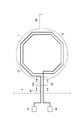
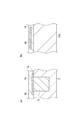
- FIG. 1 is a plan view showing a mirror drive device according to an embodiment.
- FIG. 2 is a plan view showing a configuration of a drive coil of the mirror drive device shown in FIG.
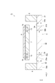
- FIG. 3 is a diagram showing a cross-sectional configuration along the line III-III in FIG.
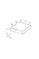
- FIG. 4 is a perspective view showing a permanent magnet.
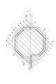
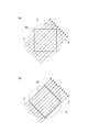
- FIG. 5 schematically shows a magnetic field.
- FIG. 6 is a view showing a part of the cross-sectional configuration of the movable part.
- 7 (a) is a diagram showing a cross-sectional structure along the line aa in FIG. 2
- FIG. 7 (b) is a diagram showing a cross-sectional structure along the line b-b in FIG.
- FIG. 8 is a view schematically showing the relationship between the drive coil of the comparative example and the magnetic field.
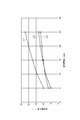
- FIG. 9 is a graph showing the relationship between the drive current and the optical deflection angle.
- FIG. 1 is a plan view showing a mirror drive device according to an embodiment.
- FIG. 2 is a plan view showing a configuration of a drive coil of the mirror drive device shown in FIG.
- FIG. 3 is a diagram showing a cross-sectional configuration along the line III-III in FIG.
- the mirror drive device 1 includes a permanent magnet 3, a fixed frame (support portion) 5, a movable portion 7 and a mirror 9.
- the permanent magnet 3 is in the form of a flat plate having a rectangular shape.
- the permanent magnet 3 is disposed below the movable portion 7.
- the permanent magnet 3 has a pair of main surfaces 3a and 3b.
- the permanent magnet 3 forms a magnetic field (magnetic field) around the movable portion 7 (around the drive coil 12 described later).
- FIG. 4 is a perspective view showing a permanent magnet.
- the permanent magnet 3 has a first magnetic portion 30, a second magnetic portion 31 and a third magnetic portion 32.
- the first magnetic unit 30 and the second magnetic unit 31 are respectively disposed on one end side and the other end side in the diagonal direction of the bottom surface of the permanent magnet 3 in the permanent magnet 3.
- the third magnetic unit 32 is disposed between the first magnetic unit 30 and the second magnetic unit 31.
- the interface 33 between the first magnetic unit 30 and the third magnetic unit 32 and the interface 34 between the third magnetic unit 32 and the second magnetic unit 31 are both parallel to the Z axis and both the X axis and the Y axis. It is a plane that intersects
- the first magnetic unit 30 has a magnetic pole 30a of a first polarity and a magnetic pole 30b of a second polarity different from the first polarity.
- the second magnetic portion 31 has a magnetic pole 31a of a first polarity and a magnetic pole 31b of a second polarity.
- the third magnetic portion 32 has a magnetic pole 32a of a first polarity and a magnetic pole 32b of a second polarity.
- the magnetic pole 32 a is disposed on the side of the third magnetic unit 32 facing the first magnetic unit 30.
- the magnetic pole 32 b is disposed on the side of the third magnetic portion 32 facing the second magnetic portion 31.
- the first polarity is the polarity of the S pole
- the second polarity is the polarity of the N pole
- the first polarity may be the polarity of the N pole
- the second polarity may be the polarity of the S pole.
- the first magnetic unit 30, the third magnetic unit 32, and the second magnetic unit 31 constitute a Halbach arrangement. Specifically, in the first magnetic unit 30, the magnetic pole 30a of the first polarity and the magnetic pole 30b of the second polarity of the first magnetic unit 30 are opposed in the Z-axis direction. In the third magnetic unit 32 adjacent to the first magnetic unit 30, the magnetic pole 32a of the first polarity and the magnetic pole 32b of the second polarity of the third magnetic unit 32 oppose each other in a direction parallel to the X and Y directions. .
- the magnetic pole 31a of the first polarity and the magnetic pole 31b of the second polarity are They are opposed in the Z-axis direction.
- the directions in which the two magnetic poles of each are opposed are perpendicular to each other.
- the direction of the magnetic field formed by the permanent magnet 3 forms a predetermined angle.
- the magnetic field F is formed along the surface direction of the main surface 7 a of the movable portion 7 described later, and the direction of the magnetic field F connects the fixed frame 5 and the movable portion 7.
- An angle of about 45 ° is formed with respect to a straight line L including at least a connection point C with the movable part 7 in the linear torsion bars (connection members) 10a and 10b (connecting the connection point C).
- the thickness of the permanent magnet 3 can be set to, for example, about 2 mm to 3 mm.
- the fixed frame 5 is a frame having a rectangular shape.
- the fixed frame 5 is disposed on the main surface 3 a of the permanent magnet 3.
- the thickness of the fixed frame 5 can be set to, for example, about 250 ⁇ m to 300 ⁇ m.
- the movable portion 7 is located in the opening of the fixed frame 5.
- the movable portion 7 has a flat plate shape exhibiting a circular shape.
- the circular shapes referred to here include perfect circles and ellipses.
- the movable portion 7 has a true circular shape.
- the movable portion 7 is swingably supported by the fixed frame 5 via the torsion bars 10a and 10b.
- the torsion bars 10 a and 10 b have a linear shape, and connect the fixed frame 5 and the movable portion 7.
- the torsion bars 10a and 10b are disposed at positions sandwiching the movable portion 7 from both sides.
- the extension direction of the torsion bars 10a and 10b (or the swing axis (the extension direction of the swing axis)), the torsion bars 10a and 10b, and The straight line L including the connection points C with the movable portion 7 is in the same direction.
- the torsion bar is not limited to a linear configuration, and may be, for example, a serpentine shape having a linear portion and a plurality of folded portions alternately connecting both ends of the linear portion.
- each of the connection portion between the torsion bar and the fixed frame 5 and the connection portion between the torsion bar and the movable portion 7 may be located on the same straight line or located on the same straight line. You do not have to.
- the predetermined angle with the direction of the magnetic field F is either the extension direction of the torsion bar (connection member) or the extension direction of the swing axis.
- the mirror 9 is disposed on the major surface 7 a of the movable portion 7. In the present embodiment, as shown in FIG. 1, the mirror 9 has a circular shape.
- the mirror 9 is a light reflecting film made of a metal thin film. Examples of the metal material used for the mirror 9 include aluminum (Al), gold (Au) and silver (Ag).
- the drive coil 12 is disposed in the movable portion 7.
- the drive coil 12 is disposed below the mirror 9 and embedded in the movable portion 7.
- the drive coil 12 is disposed at an inner side of the mirror 9, that is, at a position covered (hidden) by the mirror 9 when viewed in a direction orthogonal to the major surface 7 a of the movable portion 7.
- the drive coil 12 has a polygonal shape, more specifically a 2n square shape (n is an integer and 3 or more (n ⁇ ⁇ , as seen in the direction orthogonal to the major surface 7a of the movable portion 7). 3), and in the present embodiment, it has an octagonal shape.
- At least one side of the drive coil 12 is orthogonal to the direction of the magnetic field.
- the drive coil 12 has an octagonal shape, and as shown in FIG. 5, two sides of the eight sides are orthogonal to the direction of the magnetic field F, and the other two sides are the magnetic field F. And intersect.
- FIG. 6 is a view showing a cross-sectional configuration of the drive coil in the movable portion.
- the movable portion 7 includes a base 14, a drive coil 12, a cover layer 16, and an insulating layer 18.
- the base 14 has a groove 20 having a shape corresponding to the drive coil 12. That is, the groove portion 20 is formed in an octagonal shape as viewed from the direction orthogonal to the main surface 14a (main surface 7a).
- the groove portion 20 can be formed, for example, by forming a mask of a predetermined pattern on the surface of the substrate 14 and subsequently etching the substrate 14 through the mask.
- the base 14 is made of, for example, Si.
- the thickness of the base 14 can be set to, for example, about 20 ⁇ m to 60 ⁇ m.
- An insulating layer 22 is disposed on the major surface 14 a of the base 14 and the inner wall surface of the groove 20.
- the insulating layer 22 is a thermal oxide film obtained by thermally oxidizing the base 14.
- the insulating layer 22 is made of, for example, SiO 2 .
- the seed layer 24 is disposed in the groove 20 and on the inner wall surface of the insulating layer 22. That is, the seed layer 24 is located between the insulating layer 22 and the drive coil 12.
- the seed layer 24 is obtained by sputtering a dense metal material having adhesiveness to the metal material constituting the drive coil 12 on the substrate 14 (insulating layer 22).
- a metal material which constitutes seed layer 24 TiN is mentioned, for example.
- a metal material constituting the drive coil 12 is disposed in the groove portion 20 and on the seed layer 24, a metal material constituting the drive coil 12 is disposed.
- the drive coil 12 is obtained by embedding the metal material on the seed layer 24 by a damascene method.
- plating, sputtering or CVD may be mentioned.
- the main surface 14a side may be planarized by chemical mechanical polishing (CMP).
- CMP chemical mechanical polishing
- the boundary portion 26 of the drive coil 12 in contact with the seed layer 24 may be locally thinned due to a potential difference or the like generated between the drive coil 12 and the seed layer 24.
- the metal material include Cu or Au.
- the thickness of the drive coil 12 can be set to, for example, about 5 ⁇ m to 10 ⁇ m.
- the covering layer 16 extends onto the major surface 14 a so as to cover the opening of the groove 20. That is, the cover layer 16 covers the entire surface of the drive coil 12 on the main surface 14 a side and also covers the periphery of the groove 20 of the base 14 as viewed in the direction orthogonal to the main surface 14 a.
- the covering layer 16 is obtained by depositing a metal material on the entire upper surface of the substrate 14 by, for example, a sputtering method or a CVD method and subsequently patterning it.
- the metal material forming the covering layer 16 has a function of suppressing the diffusion of the metal material forming the driving coil 12.
- the metal material constituting the covering layer 16 include Al or an alloy containing Al.
- alloys containing Al include Al-Si alloys, Al-Cu alloys, and Al-Si-Cu alloys.
- the composition ratio of the Al—Si alloy can be, for example, 99% of Al and 1% of Si.
- the composition ratio of the Al—Cu alloy can be, for example, 99% of Al and 1% of Cu.
- the composition ratio of the Al—Si—Cu alloy can be, for example, 98% of Al, 1% of Si, and 1% of Cu.
- the thickness of the covering layer 16 can be set to, for example, about 1 ⁇ m.
- the insulating layer 18 is disposed to cover the substrate 14 and the covering layer 16.
- a material for forming the insulating layer 18 include, for example, SiO 2, SiN or TEOS.
- the mirror 9 is disposed on the insulating layer 18.
- one end of the lead conductor 40 is electrically connected to one end of the drive coil 12.
- One end of the lead conductor 42 is electrically connected to the other end of the drive coil 12.
- the lead conductors 40, 42 extend along the torsion bar 10 a and are drawn to the fixed frame 5.
- the other ends of the lead conductors 40 and 42 are electrically connected to the electrodes 44 and 46 disposed on the fixed frame 5.
- the electrodes 44 and 46 are connected to a power supply (not shown).
- FIG. 7 (a) is a diagram showing a cross-sectional structure along the line aa in FIG. 2
- FIG. 7 (b) is a diagram showing a cross-sectional structure along the line b-b in FIG.
- the drive coil 12 (wiring) is formed by a damascene wire made of Cu or Au and a material.
- a wire connecting the lead conductors 40 and 42 and the electrodes 44 and 46 is formed by damascene wiring.
- the lead conductor 40 is more difficult to plastically deform than a material such as Al or an alloy containing Al, that is, Cu forming the drive coil 12. It is formed of a material.
- the other end of the drive coil 12 and one end of the lead conductor 40 are electrically connected by a connection (not shown).
- a connection (not shown).
- the drive coil 12 and the lead-out conductor 40 have different height positions. Therefore, the drive coil 12 and the lead conductor 40 are connected by the connection portion extending in the direction orthogonal to the main surface 7 a of the movable portion 7.
- FIG. 7 (b) shows the lead conductor 40
- the lead conductor 42 also has a similar configuration.
- the movable portion 7 has a circular shape.
- the air resistance can be reduced compared to the structure in which the movable portion 7 has a rectangular shape, and the weight can be reduced, so that the moment of inertia can be reduced.
- the air resistance is 1.45 ⁇ 10 -3 [N] in the simulation, and the conventional mirror drive in which the drive coil is disposed around the mirror (movable portion) In the device, it is 1.70 ⁇ 10 ⁇ 3 [N]. Therefore, in the mirror drive device 1 of this embodiment, the air resistance in the movable portion 7 can be reduced.
- the permanent magnet 3 is disposed below the movable portion 7, and the drive coil 12 exhibits an octagonal shape when viewed from the direction orthogonal to the main surface 7 a of the movable portion 7.
- the magnetic field F having an angle of 45 ° with respect to the extending direction of the torsion bars 10a and 10b (connection members) or the extending direction of the swing axis is generated.
- the direction of the magnetic field F is orthogonal to the direction of the current flowing to the two sides of the drive coil 12, and the direction of the current flowing to the other two sides intersects the direction of the magnetic field F , Lorentz force can be generated effectively. Therefore, the mirror drive device 1 can efficiently obtain the driving force.
- FIG. 8 is a diagram schematically showing the relationship between the drive coil of the comparative example and the magnetic field.
- the drive coil 50 has a rectangular shape (n is smaller than 3 in a 2n square shape)
- the Lorentz force is not easily generated, and the driving force is reduced.
- the area that can be used below the mirror 9 is small, so it is difficult to secure the length of the drive coil 50. As a result, the driving force is reduced.
- the drive coil 50 when the sides of the drive coil 50 having a rectangular shape are disposed orthogonal to the magnetic field F, the drive coil 50 does not intersect at all with the magnetic field F (parallel to the magnetic field F). ) There is an edge.
- the two sides that do not intersect the magnetic field F correspond to one half of the length of the drive coil 50, so that sufficient driving force can be obtained even when the other two sides are orthogonal to the magnetic field F. Can not.
- the wiring to the torsion bars 10a and 10b must be taken out from the corner of the drive coil 50. In this case, the load (stress) tends to be concentrated at the corner, which may increase the possibility of disconnection of the wiring.
- the shape of the drive coil 12 is a polygonal shape (octagonal shape) that is equal to or more than a hexagonal shape.
- the mirror driving device 1 there is an edge that is orthogonal to the magnetic field F, and another edge that is not orthogonal to the magnetic field F but that intersects.
- the side which is not orthogonal to or intersects with the magnetic field F is 1/3 of the entire length when the drive coil 12 is octagonal.
- the mirror drive device 1 can efficiently obtain the driving force.
- FIG. 9 is a graph showing the relationship between the drive current and the optical deflection angle.
- the horizontal axis indicates the drive current [mA]
- the vertical axis indicates the optical deflection angle [°].
- the line L1 shows the result of the mirror drive device 1 of the present embodiment
- the lines L2 and L3 show the results of the conventional mirror drive device.
- the number of turns of the drive coil 12 of the mirror drive device 1 of the present embodiment is “3”, and the distance between the drive coils 12 is 0.6 ⁇ m.
- the conventional mirror drive device has a configuration in which a coil is disposed around a mirror (movable portion), and the number of turns of the drive coil is “1” (L2), “3” (L3), and The intervals are respectively 1 ⁇ m (L2) and 0.6 ⁇ m (L3).
- an optical deflection angle of about twice that of the conventional mirror driving device is obtained. This is because, in the mirror driving device 1, the movable portion 7 has a circular shape and the driving coil 12 is disposed below the mirror 9, thereby reducing the air resistance and reducing the weight. doing. As described above, in the mirror driving device 1, a high driving force is obtained as compared with the conventional configuration.
- the drive coil 12 is disposed below the mirror 9 and inside the mirror 9 when viewed from a direction orthogonal to the major surface 7 a of the movable portion 7.
- the area of the mirror is necessarily reduced if miniaturization is attempted.
- downsizing can be achieved while securing the area of the mirror 9.
- the movable portion 7 has a base 14 having a groove 20 in which the drive coil 12 is embedded, and the drive coil 12 is made of Cu which is a metal material disposed in the groove 20.
- the flatness of the main surface 7a of the movable portion 7 can be secured.
- the electrical resistivity can be reduced, and a large current can be supplied to the drive coil 12. As a result, a greater Lorentz force can be generated, and thus a driving force can be obtained.
- the lead conductors 40, 42 disposed on the torsion bar 10a are made of Al or an alloy containing Al.
- the stress is concentrated at the central portion of the linear torsion bar 10a. Therefore, in the mirror driving device 1, since the lead conductors 40 and 42 use Al or an alloy containing Al which is less likely to be plastically deformed than the material (Cu or Au) forming the drive coil 12, a torsion bar to which stress is applied The strength of the lead conductors 40, 42 at the central portion of 10a can be secured. Therefore, in the mirror drive device 1, the mechanical strength of the torsion bar 10 a can be secured, and breakage or the like of the lead conductors 40, 42 due to stress concentration can be suppressed.
- the structures of the lead conductors 40 and 42 arranged on the torsion bar 10a, the wiring at the connection point C between the torsion bar 10a and the fixed frame 5, and the connection point C between the torsion bar 10a and the movable portion 7 are different from each other.
- the embodiment includes a support portion, a torsion bar extending in the same straight line, a movable portion pivotally supported relative to the support portion via the torsion bar, a mirror disposed on the movable portion, and a movable portion.
- a drive electric element for example, a drive coil or an electrode of a piezoelectric body formed, and a wire disposed on the torsion bar along the extension direction of the torsion bar and connected to the drive electric element;
- the wiring in the vicinity of the connection between the bar and the support and in the vicinity of the connection between the torsion bar and the movable part is made of Cu, which is the first metal material disposed in the groove.
- Singh is configured as a wiring, the wiring in the vicinity of the center portion of the torsion bar may be regarded as a mirror drive device is constituted by a second metallic material difficult to plastically deform than the first metal material.
- the present invention is not limited to the above embodiment.
- the configuration in which the movable portion 7 has a true circular shape is described as an example, but the movable portion 7 may have an elliptical shape.
- the configuration in which the mirror 9 has a circular shape is described as an example, but the mirror 9 may have another shape.
- the configuration in which the drive coil 12 has an octagonal shape has been described as an example, but the drive coil 12 may have a 2n square shape (n ⁇ 3) or may have a hexagonal shape or the like. Also in the drive coil 12 having a hexagonal shape, the two sides are orthogonal to the magnetic field F, and the other two sides intersect the magnetic field F.
- the number of turns of the drive coil 12 is two in the above embodiment, the number of turns of the drive coil 12 may be appropriately set according to the design of the mirror drive device 1.
- the lead conductors 40, 42 of the drive coil 12 are drawn to the electrodes 44, 46 through one torsion bar 10a.
- the lead conductor 40 is a torsion bar 10a and the lead conductor 42 is a torsion bar It may be arranged at 10b. That is, the lead conductors 40 and 42 may be drawn to the electrodes 44 and 46 one by one via the torsion bars 10a and 10b, respectively.
- the torsion bar is selected according to the output of the signal. Damage to 10a and 10b can be detected and operation can be interrupted. Further, by arranging the lead conductors 40 and 42 respectively, it is possible to further reduce the stress and to prevent a short circuit between the lead conductors 40 and 42.
- linear torsion bars 10a and 10b have been described as an example in the above embodiment, the configuration of the torsion bars is not limited to this, and may be meandering as described above.
- the configuration in which the entire drive coil 12 is disposed inside the mirror 9 is described as an example, but a part of the drive coil 12 may be disposed inside the mirror 9.
- the fixed frame 5 and the movable portion 7 are connected via the torsion bars 10a and 10b to move the torsion bars 10a and 10b (connection members) in the extending direction or around the extending direction of the swing axis.
- 7 is described as an example of a one-dimensional drive type apparatus for oscillating the mirror 9 to drive the mirror 9 one-dimensionally, but the mirror drive apparatus is a two-dimensional drive type apparatus for driving the mirror 9 two-dimensionally May be
- the mirror drive device includes a support portion, a first movable portion swingably supported by the support portion, a second movable portion swingably supported by the first movable portion, and a second movable portion And the first coil disposed in the first movable portion, and the second coil disposed in the second movable portion.
- the movable portion 7 of the above embodiment corresponds to a second movable portion
- the drive coil 12 corresponds to a second coil.
- the first movable portion and the second movable portion are provided so as to be swingable around straight lines (axes) orthogonal to each other.
- the mirror drive device is configured as a two-dimensional drive type device that drives the mirror 9 two-dimensionally.
- the direction of the magnetic field F preferably has a predetermined angle with respect to the two swing axes. This eliminates the need to arrange magnets for each axis.
- SYMBOLS 1 ... Mirror drive device, 3 ... Permanent magnet, 5 ... Fixed frame (support part), 7 ... Movable part, 7a ... Principal surface, 9 ... Mirror, 10a, 10b ... Torsion bar (connection member), 12 ... Drive coil, 14: base material, 20: groove portion, C: connection point, L: straight line.
Landscapes
- Physics & Mathematics (AREA)
- Electromagnetism (AREA)
- General Physics & Mathematics (AREA)
- Optics & Photonics (AREA)
- Chemical & Material Sciences (AREA)
- Analytical Chemistry (AREA)
- Engineering & Computer Science (AREA)
- Computer Hardware Design (AREA)
- Microelectronics & Electronic Packaging (AREA)
- Mechanical Light Control Or Optical Switches (AREA)
- Micromachines (AREA)
- Mechanical Optical Scanning Systems (AREA)
Abstract
Provided is a mirror drive device that makes it possible to efficiently obtain driving force. The mirror device (1) is provided with: a fixed frame (5); a movable section (7) that has a circular shape and that is swingably supported with respect to the fixed frame (5) via torsion bars (10a, 10b) that extend on the same straight line; a mirror (9) that is arranged on the main surface (7a) of the movable section (7); and a permanent magnet (3) that forms a magnetic field around the movable section (7). The movable section (7) comprises a drive coil (12) that is arranged below the mirror (9). The drive coil (12) has a 2n-sided shape (n is an integer of 3 or more) when viewed from a direction that is orthogonal to the main surface (7a) and at least one side of said shape is orthogonal to the direction of the magnetic field (F).
Description
本発明は、ミラー駆動装置に関する。
The present invention relates to a mirror drive device.
近年、微少な大きさの機械的要素及び電子回路要素を融合したMEMS(Micro Electro Mechanical System)技術(マイクロマシン技術ともいう)を用いたミラー駆動装置の研究が盛んに行われている。ミラー駆動装置の一例としては、例えば特許文献1に記載されたものが知られている。
2. Description of the Related Art In recent years, research on mirror drive devices using MEMS (Micro Electro Mechanical System) technology (also referred to as micromachine technology) in which mechanical elements and electronic circuit elements of very small size are integrated has been actively conducted. As an example of a mirror drive device, what was described, for example in patent document 1 is known.
特許文献1に記載のミラー駆動装置は、支持部にトーションバー部を介して揺動駆動可能に設けられたミラー部と、支持部を挟む位置に配置された一対の永久磁石と、を備えている。ミラー部は、表面に反射膜が形成されていると共に、その表面と反射膜との間にミラー部の形状に沿った電磁コイルが設けられている。
The mirror driving device described in Patent Document 1 includes a mirror portion provided in a support portion so as to be able to swing and drive via a torsion bar portion, and a pair of permanent magnets disposed at positions sandwiching the support portion. There is. The mirror portion has a reflective film formed on the surface, and an electromagnetic coil along the shape of the mirror portion is provided between the surface and the reflective film.
ミラー部の駆動力を効率的に得るためには、ミラー部の軽量化を図り、慣性モーメントを低減させる必要がある。ここで、一般に、ミラー部の反射膜に照射されたときのレーザー光の形状は円形形状を呈している。そのため、上記従来のミラー駆動装置のようにミラー部が矩形形状を呈している構造では、レーザー光が照射されない無駄な領域(隅部)が存在する。その結果、従来のミラー駆動装置では、ミラー部が重いために慣性モーメントが大きく、駆動力を確保し難い。また、従来のミラー駆動装置の構造では、ミラー部(可動板)の形状に沿ってコイルを形成するため、永久磁石により形成される磁場と電磁コイルに流れる電流の向きによっては直交する辺が存在しない場合や、交差しない部分が多く存在する場合があるため、駆動力を効率的に得ることができない。
In order to efficiently obtain the driving force of the mirror portion, it is necessary to reduce the weight of the mirror portion and reduce the moment of inertia. Here, in general, the shape of the laser light when irradiated to the reflection film of the mirror portion has a circular shape. Therefore, in the structure in which the mirror portion has a rectangular shape as in the above-described conventional mirror driving device, there are useless regions (corners) where the laser light is not irradiated. As a result, in the conventional mirror driving device, since the mirror portion is heavy, the moment of inertia is large, and it is difficult to secure the driving force. Moreover, in the structure of the conventional mirror drive device, since the coil is formed along the shape of the mirror portion (movable plate), there are sides orthogonal to each other depending on the direction of the magnetic field formed by the permanent magnet and the current flowing in the electromagnetic coil. In the case of not being performed or there are many non-intersecting portions, the driving force can not be obtained efficiently.
本発明は、駆動力を効率的に得ることができるミラー駆動装置を提供することを目的とする。
An object of the present invention is to provide a mirror drive device capable of efficiently obtaining a driving force.
本発明の一側面に係るミラー駆動装置は、支持部と、連結部材を介して、支持部に対して揺動可能に支持されると共に、円形形状を呈する可動部と、可動部の主面上に配置されたミラーと、可動部の周囲に磁場を形成する磁石と、を備え、可動部は、ミラーの下方で且つ主面に対して直交する方向から見てミラーの内側に少なくとも一部が配置された駆動コイルを有し、駆動コイルは、主面に対して直交する方向から見て2n角形形状(nは整数で且つ3以上)を呈しており、その少なくとも一辺が磁場の方向に直交していることを特徴とする。
A mirror drive device according to one aspect of the present invention includes a support portion, a movable portion swingably supported relative to the support portion via the connection member, and a movable portion having a circular shape, and a main surface of the movable portion And a magnet for forming a magnetic field around the movable portion, the movable portion being at least partially inside the mirror when viewed from a direction below the mirror and orthogonal to the main surface It has a drive coil disposed, and the drive coil has a 2n square shape (n is an integer and 3 or more) when viewed from the direction orthogonal to the main surface, and at least one side thereof is orthogonal to the direction of the magnetic field It is characterized by
このミラー駆動装置では、可動部は円形形状を呈している。これにより、可動部が矩形形状を呈する構造に比べて空気抵抗を小さくすることができると共に、軽量化が図れるため慣性モーメントを低減させることができる。また、ミラー駆動装置では、駆動コイルは、主面に対して直交する方向から見て2n角形形状(nは整数で且つ3以上)を呈しており、その少なくとも一辺が磁界の方向に直交している。これにより、磁場の方向と駆動コイルに流れる電流の向きとが直交するため、ローレンツ力を効果的に発生させることができる。したがって、ミラー駆動装置では、駆動力を効率的に得ることができる。
In this mirror drive device, the movable portion has a circular shape. As a result, the air resistance can be reduced as compared with the structure in which the movable portion has a rectangular shape, and the weight can be reduced, so that the moment of inertia can be reduced. Further, in the mirror drive device, the drive coil has a 2n square shape (n is an integer and 3 or more) when viewed in the direction orthogonal to the main surface, and at least one side thereof is orthogonal to the direction of the magnetic field There is. Thereby, since the direction of the magnetic field and the direction of the current flowing in the drive coil are orthogonal to each other, the Lorentz force can be effectively generated. Therefore, in the mirror driving device, the driving force can be obtained efficiently.
一実施形態においては、磁場は、可動部の主面の面方向に沿って形成されており、磁場の方向は、主面に対して直交する方向から見て、揺動軸に対して所定の角度を成している。これにより、駆動コイルに流れる電流と磁場の方向とが直交するため、ローレンツ力をより効果的に発生させることができる。したがって、駆動力を効率的に得ることができる。
In one embodiment, the magnetic field is formed along the surface direction of the main surface of the movable portion, and the direction of the magnetic field is predetermined with respect to the swing axis when viewed from the direction orthogonal to the main surface. It makes an angle. Thereby, since the current flowing through the drive coil and the direction of the magnetic field are orthogonal to each other, the Lorentz force can be generated more effectively. Therefore, the driving force can be obtained efficiently.
一実施形態においては、可動部は、駆動コイルが埋め込まれる溝部を有する基材を有し、駆動コイルは、溝部内に配置された金属材料であるCuによって構成されていてもよい。このように、駆動コイルを溝部に金属材料を配置するダマシン法により形成することにより、可動部の主面の平坦性を確保できる。また、駆動コイルをCuで構成することにより、電気抵抗率を小さくすることができ、駆動コイルに大きな電流を流すことができる。その結果、より大きなローレンツ力を発生させることができるため、駆動力をより効果的に得ることができる。
In one embodiment, the movable portion may have a base having a groove in which the drive coil is embedded, and the drive coil may be made of Cu, which is a metallic material disposed in the groove. Thus, the flatness of the main surface of the movable portion can be secured by forming the drive coil by the damascene method in which the metal material is disposed in the groove. Further, by making the drive coil of Cu, the electrical resistivity can be reduced, and a large current can be supplied to the drive coil. As a result, since a larger Lorentz force can be generated, the driving force can be obtained more effectively.
本発明によれば、駆動力を効率的に得ることができる。
According to the present invention, the driving force can be obtained efficiently.
本発明の実施形態について図面を参照して説明するが、以下の本実施形態は、本発明を説明するための例示であり、本発明を以下の内容に限定する趣旨ではない。説明において、同一要素又は同一機能を有する要素には同一符号を用いることとし、重複する説明は省略する。
Embodiments of the present invention will be described with reference to the drawings, but the following present embodiments are exemplifications for describing the present invention, and are not intended to limit the present invention to the following contents. In the description, the same elements or elements having the same function will be denoted by the same reference numerals, and redundant description will be omitted.
図1は、一実施形態に係るミラー駆動装置を示す平面図である。図2は、図1に示すミラー駆動装置の駆動コイルの構成を示す平面図である。図3は、図1におけるIII-III線に沿った断面構成を示す図である。各図に示されるように、ミラー駆動装置1は、永久磁石3と、固定フレーム(支持部)5と、可動部7と、ミラー9と、を備えている。
FIG. 1 is a plan view showing a mirror drive device according to an embodiment. FIG. 2 is a plan view showing a configuration of a drive coil of the mirror drive device shown in FIG. FIG. 3 is a diagram showing a cross-sectional configuration along the line III-III in FIG. As shown in the respective drawings, the mirror drive device 1 includes a permanent magnet 3, a fixed frame (support portion) 5, a movable portion 7 and a mirror 9.
永久磁石3は、矩形状を呈する平板状を成している。永久磁石3は、可動部7の下方に配置されている。永久磁石3は、一対の主面3a,3bを有する。永久磁石3は、可動部7の周囲(後述する駆動コイル12の周囲)に磁場(磁界)を形成する。図4は、永久磁石を示す斜視図である。図3及び図4に示されるように、永久磁石3は、第1磁性部30と、第2磁性部31と、第3磁性部32と、を有している。図4に示されるように、第1磁性部30及び第2磁性部31は、それぞれ、永久磁石3において、永久磁石3の底面の対角線方向における一端側及び他端側に配置されている。第3磁性部32は、第1磁性部30と第2磁性部31との間に配置されている。第1磁性部30と第3磁性部32との境界面33、及び第3磁性部32と第2磁性部31との境界面34は、Z軸に平行で、かつX軸及びY軸の両方と交差する平面である。
The permanent magnet 3 is in the form of a flat plate having a rectangular shape. The permanent magnet 3 is disposed below the movable portion 7. The permanent magnet 3 has a pair of main surfaces 3a and 3b. The permanent magnet 3 forms a magnetic field (magnetic field) around the movable portion 7 (around the drive coil 12 described later). FIG. 4 is a perspective view showing a permanent magnet. As shown in FIG. 3 and FIG. 4, the permanent magnet 3 has a first magnetic portion 30, a second magnetic portion 31 and a third magnetic portion 32. As shown in FIG. 4, the first magnetic unit 30 and the second magnetic unit 31 are respectively disposed on one end side and the other end side in the diagonal direction of the bottom surface of the permanent magnet 3 in the permanent magnet 3. The third magnetic unit 32 is disposed between the first magnetic unit 30 and the second magnetic unit 31. The interface 33 between the first magnetic unit 30 and the third magnetic unit 32 and the interface 34 between the third magnetic unit 32 and the second magnetic unit 31 are both parallel to the Z axis and both the X axis and the Y axis. It is a plane that intersects
第1磁性部30は、第1極性の磁極30aと、第1極性とは異なる第2極性の磁極30bと、を有する。第2磁性部31は、第1極性の磁極31aと、第2極性の磁極31bと、を有する。第3磁性部32は、第1極性の磁極32aと、第2極性の磁極32bと、を有する。磁極32aは、第3磁性部32における、第1磁性部30と対向する側に配置されている。磁極32bは、第3磁性部32における、第2磁性部31と対向する側に配置されている。本実施形態では、第1極性はS極の極性であり、第2極性はN極の極性である。逆に、第1極性がN極の極性であり、第2極性がS極の極性であってもよい。
The first magnetic unit 30 has a magnetic pole 30a of a first polarity and a magnetic pole 30b of a second polarity different from the first polarity. The second magnetic portion 31 has a magnetic pole 31a of a first polarity and a magnetic pole 31b of a second polarity. The third magnetic portion 32 has a magnetic pole 32a of a first polarity and a magnetic pole 32b of a second polarity. The magnetic pole 32 a is disposed on the side of the third magnetic unit 32 facing the first magnetic unit 30. The magnetic pole 32 b is disposed on the side of the third magnetic portion 32 facing the second magnetic portion 31. In the present embodiment, the first polarity is the polarity of the S pole, and the second polarity is the polarity of the N pole. Conversely, the first polarity may be the polarity of the N pole, and the second polarity may be the polarity of the S pole.
第1磁性部30、第3磁性部32及び第2磁性部31は、ハルバッハ配列を構成している。具体的には、第1磁性部30において、第1極性の磁極30aと第1磁性部30の第2極性の磁極30bとは、Z軸方向において対向している。第1磁性部30に隣接する第3磁性部32において、第1極性の磁極32aと第3磁性部32の第2極性の磁極32bとは、X,Y方向に平行な方向において対向している。第3磁性部32に隣接し、且つ第3磁性部32に関して第1磁性部30の反対側に位置する第2磁性部31において、第1極性の磁極31aと第2極性の磁極31bとは、Z軸方向において対向している。このように、第1磁性部30、第3磁性部32、及び第2磁性部31のうち隣り合う2つにおいて、それぞれが有する2つの磁極が対向する方向は、互いに垂直な方向である。
The first magnetic unit 30, the third magnetic unit 32, and the second magnetic unit 31 constitute a Halbach arrangement. Specifically, in the first magnetic unit 30, the magnetic pole 30a of the first polarity and the magnetic pole 30b of the second polarity of the first magnetic unit 30 are opposed in the Z-axis direction. In the third magnetic unit 32 adjacent to the first magnetic unit 30, the magnetic pole 32a of the first polarity and the magnetic pole 32b of the second polarity of the third magnetic unit 32 oppose each other in a direction parallel to the X and Y directions. . In the second magnetic portion 31 adjacent to the third magnetic portion 32 and located on the opposite side of the first magnetic portion 30 with respect to the third magnetic portion 32, the magnetic pole 31a of the first polarity and the magnetic pole 31b of the second polarity are They are opposed in the Z-axis direction. As described above, in two adjacent ones of the first magnetic unit 30, the third magnetic unit 32, and the second magnetic unit 31, the directions in which the two magnetic poles of each are opposed are perpendicular to each other.
永久磁石3により形成される磁場の方向は、所定の角度を成している。詳細には、図5に示されるように、磁場Fは、後述する可動部7の主面7aの面方向に沿って形成され、磁場Fの方向は、固定フレーム5と可動部7とを連結する直線状のトーションバー(連結部材)10a,10bにおける可動部7との接続箇所Cを少なくとも含む(接続箇所Cを繋ぐ)直線Lに対して約45°の角度を成している。永久磁石3の厚さは、例えば2mm~3mm程度に設定することができる。
The direction of the magnetic field formed by the permanent magnet 3 forms a predetermined angle. Specifically, as shown in FIG. 5, the magnetic field F is formed along the surface direction of the main surface 7 a of the movable portion 7 described later, and the direction of the magnetic field F connects the fixed frame 5 and the movable portion 7. An angle of about 45 ° is formed with respect to a straight line L including at least a connection point C with the movable part 7 in the linear torsion bars (connection members) 10a and 10b (connecting the connection point C). The thickness of the permanent magnet 3 can be set to, for example, about 2 mm to 3 mm.
固定フレーム5は、矩形状を呈する枠体である。固定フレーム5は、永久磁石3の主面3a上に配置されている。固定フレーム5の厚さは、例えば250μm~300μm程度に設定することができる。
The fixed frame 5 is a frame having a rectangular shape. The fixed frame 5 is disposed on the main surface 3 a of the permanent magnet 3. The thickness of the fixed frame 5 can be set to, for example, about 250 μm to 300 μm.
可動部7は、固定フレーム5の開口内に位置している。可動部7は、円形形状を呈する平板状を成している。ここで言う円形形状には、真円及び楕円を含む。本実施形態では、可動部7は、真円形状を呈している。可動部7は、トーションバー10a,10bを介して、固定フレーム5に対して揺動可能に支持されている。トーションバー10a,10bは、直線状を呈しており、固定フレーム5と可動部7とを連結している。トーションバー10a,10bは、可動部7を両側から挟む位置に配置されている。本実施形態では、トーションバー10a,10bが直線状を呈しているため、トーションバー10a,10bの延在方向(もしくは揺動軸(揺動軸の延びる方向))と、トーションバー10a,10bと可動部7との接続箇所Cのそれぞれを含む上記直線Lとは、同一方向とされている。なお、トーションバーは、直線状である構成に限らず、例えば、直線部分と、この直線部分の両端を交互に連結する複数の折り返し部分と、を有する蛇行形状であってもよい。このような構成において、トーションバーと固定フレーム5との接続箇所と、トーションバーと可動部7との接続箇所とのそれぞれは、同一直線上に位置していてもよいし、同一直線上に位置していなくてもよい。同一直線上に位置していない場合、磁場Fの方向と所定の角度を成すのはトーションバー(連結部材)の延在方向もしくは揺動軸の延びる方向のいずれかである。
The movable portion 7 is located in the opening of the fixed frame 5. The movable portion 7 has a flat plate shape exhibiting a circular shape. The circular shapes referred to here include perfect circles and ellipses. In the present embodiment, the movable portion 7 has a true circular shape. The movable portion 7 is swingably supported by the fixed frame 5 via the torsion bars 10a and 10b. The torsion bars 10 a and 10 b have a linear shape, and connect the fixed frame 5 and the movable portion 7. The torsion bars 10a and 10b are disposed at positions sandwiching the movable portion 7 from both sides. In this embodiment, since the torsion bars 10a and 10b have a linear shape, the extension direction of the torsion bars 10a and 10b (or the swing axis (the extension direction of the swing axis)), the torsion bars 10a and 10b, and The straight line L including the connection points C with the movable portion 7 is in the same direction. The torsion bar is not limited to a linear configuration, and may be, for example, a serpentine shape having a linear portion and a plurality of folded portions alternately connecting both ends of the linear portion. In such a configuration, each of the connection portion between the torsion bar and the fixed frame 5 and the connection portion between the torsion bar and the movable portion 7 may be located on the same straight line or located on the same straight line. You do not have to. When not located on the same straight line, the predetermined angle with the direction of the magnetic field F is either the extension direction of the torsion bar (connection member) or the extension direction of the swing axis.
ミラー9は、可動部7の主面7a上に配置されている。本実施形態では、図1に示されるように、ミラー9は円形形状を呈している。ミラー9は、金属薄膜により構成された光反射膜である。ミラー9に用いられる金属材料としては、例えばアルミ(Al)、金(Au)、銀(Ag)が挙げられる。
The mirror 9 is disposed on the major surface 7 a of the movable portion 7. In the present embodiment, as shown in FIG. 1, the mirror 9 has a circular shape. The mirror 9 is a light reflecting film made of a metal thin film. Examples of the metal material used for the mirror 9 include aluminum (Al), gold (Au) and silver (Ag).
可動部7には、駆動コイル12が配置されている。駆動コイル12は、ミラー9の下方に配置されており、可動部7に埋め込まれている。駆動コイル12は、可動部7の主面7aに対して直交する方向から見て、ミラー9の内側、すなわちミラー9に覆われる(隠れる)位置に配置されている。図2に示されるように、駆動コイル12は、可動部7の主面7aに直交する方向から見て、多角形形状、詳細には2n角形形状(nは整数であり且つ3以上(n≧3))を呈しており、本実施形態では、八角形形状を呈している。
The drive coil 12 is disposed in the movable portion 7. The drive coil 12 is disposed below the mirror 9 and embedded in the movable portion 7. The drive coil 12 is disposed at an inner side of the mirror 9, that is, at a position covered (hidden) by the mirror 9 when viewed in a direction orthogonal to the major surface 7 a of the movable portion 7. As shown in FIG. 2, the drive coil 12 has a polygonal shape, more specifically a 2n square shape (n is an integer and 3 or more (n 見 て, as seen in the direction orthogonal to the major surface 7a of the movable portion 7). 3), and in the present embodiment, it has an octagonal shape.
駆動コイル12は、少なくとも一辺が磁場の方向に直交している。本実施形態では、駆動コイル12が八角形形状を呈しており、図5に示されるように、八辺のうちの二辺が磁場Fの方向に直交しており、その他の二辺が磁場Fと交差している。
At least one side of the drive coil 12 is orthogonal to the direction of the magnetic field. In the present embodiment, the drive coil 12 has an octagonal shape, and as shown in FIG. 5, two sides of the eight sides are orthogonal to the direction of the magnetic field F, and the other two sides are the magnetic field F. And intersect.
続いて、駆動コイル12の詳細な構成について以下に説明する。図6は、可動部における駆動コイルの断面構成を示す図である。図6に示されるように、可動部7は、基材14と、駆動コイル12と、被覆層16と、絶縁層18と、を有する。基材14は、駆動コイル12に対応する形状を呈する溝部20を有する。すなわち、溝部20は、主面14a(主面7a)に対して直交する方向から見て、八角形形状に形成されている。溝部20は、例えば、基材14の表面に所定のパターンのマスクを形成し、続いて、当該マスクを介して基材14をエッチングすることにより形成できる。基材14は、例えば、Siで構成される。基材14の厚みは、例えば20μm~60μm程度に設定することができる。
Subsequently, the detailed configuration of the drive coil 12 will be described below. FIG. 6 is a view showing a cross-sectional configuration of the drive coil in the movable portion. As shown in FIG. 6, the movable portion 7 includes a base 14, a drive coil 12, a cover layer 16, and an insulating layer 18. The base 14 has a groove 20 having a shape corresponding to the drive coil 12. That is, the groove portion 20 is formed in an octagonal shape as viewed from the direction orthogonal to the main surface 14a (main surface 7a). The groove portion 20 can be formed, for example, by forming a mask of a predetermined pattern on the surface of the substrate 14 and subsequently etching the substrate 14 through the mask. The base 14 is made of, for example, Si. The thickness of the base 14 can be set to, for example, about 20 μm to 60 μm.
基材14の主面14a及び溝部20の内壁面には、絶縁層22が配置されている。絶縁層22は、基材14を熱酸化して得られる熱酸化膜である。絶縁層22は、例えばSiO2で構成される。溝部20内で且つ絶縁層22の内壁面には、シード層24が配置されている。すなわち、シード層24は、絶縁層22と駆動コイル12との間に位置している。シード層24は、駆動コイル12を構成する金属材料に対して付着性を有する緻密な金属材料を、基材14(絶縁層22)上にスパッタリングすることにより得られる。シード層24を構成する金属材料としては、例えばTiNが挙げられる。
An insulating layer 22 is disposed on the major surface 14 a of the base 14 and the inner wall surface of the groove 20. The insulating layer 22 is a thermal oxide film obtained by thermally oxidizing the base 14. The insulating layer 22 is made of, for example, SiO 2 . The seed layer 24 is disposed in the groove 20 and on the inner wall surface of the insulating layer 22. That is, the seed layer 24 is located between the insulating layer 22 and the drive coil 12. The seed layer 24 is obtained by sputtering a dense metal material having adhesiveness to the metal material constituting the drive coil 12 on the substrate 14 (insulating layer 22). As a metal material which constitutes seed layer 24, TiN is mentioned, for example.
溝部20内で且つシード層24上には、駆動コイル12を構成する金属材料が配置されている。駆動コイル12は、ダマシン法により、シード層24上に当該金属材料を埋め込むことにより得られる。溝部20内に当該金属材料を埋め込むための手法としては、めっき、スパッタリング又はCVDが挙げられる。
In the groove portion 20 and on the seed layer 24, a metal material constituting the drive coil 12 is disposed. The drive coil 12 is obtained by embedding the metal material on the seed layer 24 by a damascene method. As a method for embedding the metal material in the groove portion 20, plating, sputtering or CVD may be mentioned.
溝部20内に当該金属材料を配置した後に、化学機械研磨(CMP:Chemical Mechanical Polishing)によって主面14a側を平坦化してもよい。この平坦化工程においては、駆動コイル12とシード層24との間に生ずる電位差等により、駆動コイル12のうちシード層24と接する境界部26が局所的に減肉することがある。当該金属材料としては、例えばCu又はAuが挙げられる。駆動コイル12の厚さは、例えば5μm~10μm程度に設定することができる。
After the metal material is disposed in the groove portion 20, the main surface 14a side may be planarized by chemical mechanical polishing (CMP). In the planarization step, the boundary portion 26 of the drive coil 12 in contact with the seed layer 24 may be locally thinned due to a potential difference or the like generated between the drive coil 12 and the seed layer 24. Examples of the metal material include Cu or Au. The thickness of the drive coil 12 can be set to, for example, about 5 μm to 10 μm.
被覆層16は、溝部20の開口を覆うように主面14a上まで延びている。すなわち、被覆層16は、主面14aに対して直交する方向から見て、駆動コイル12のうち主面14a側の表面全体を覆うと共に、基材14のうち溝部20の周囲を覆っている。被覆層16は、例えばスパッタリング法又はCVD法により基材14上面全体に金属材料を堆積し、続いて、パターニングすることにより得られる。
The covering layer 16 extends onto the major surface 14 a so as to cover the opening of the groove 20. That is, the cover layer 16 covers the entire surface of the drive coil 12 on the main surface 14 a side and also covers the periphery of the groove 20 of the base 14 as viewed in the direction orthogonal to the main surface 14 a. The covering layer 16 is obtained by depositing a metal material on the entire upper surface of the substrate 14 by, for example, a sputtering method or a CVD method and subsequently patterning it.
被覆層16を構成する金属材料は、駆動コイル12を構成する金属材料の拡散を抑制する機能を有する。被覆層16を構成する金属材料としては、例えばAl又はAlを含む合金が挙げられる。Alを含む合金としては、Al-Si合金、Al-Cu合金、Al-Si-Cu合金が挙げられる。Al-Si合金の組成比は、例えばAlが99%、Siが1%とすることができる。Al-Cu合金の組成比は、例えばAlが99%、Cuが1%とすることができる。Al-Si-Cu合金の組成比は、例えばAlが98%、Siが1%、Cuが1%とすることができる。被覆層16の厚さは、例えば1μm程度に設定することができる。
The metal material forming the covering layer 16 has a function of suppressing the diffusion of the metal material forming the driving coil 12. Examples of the metal material constituting the covering layer 16 include Al or an alloy containing Al. Examples of alloys containing Al include Al-Si alloys, Al-Cu alloys, and Al-Si-Cu alloys. The composition ratio of the Al—Si alloy can be, for example, 99% of Al and 1% of Si. The composition ratio of the Al—Cu alloy can be, for example, 99% of Al and 1% of Cu. The composition ratio of the Al—Si—Cu alloy can be, for example, 98% of Al, 1% of Si, and 1% of Cu. The thickness of the covering layer 16 can be set to, for example, about 1 μm.
絶縁層18は、基材14上及び被覆層16上を覆うように配置されている。絶縁層18を構成する材料としては、例えばSiO2、SiN又はTEOSが挙げられる。絶縁層18上には、ミラー9が配置されている。
The insulating layer 18 is disposed to cover the substrate 14 and the covering layer 16. As a material for forming the insulating layer 18, include, for example, SiO 2, SiN or TEOS. The mirror 9 is disposed on the insulating layer 18.
図2に示されるように、駆動コイル12の一端部には、引出し導体40の一端が電気的に接続されている。駆動コイル12の他端部には、引出し導体42の一端が電気的に接続されている。引出し導体40,42は、トーションバー10aに沿って延在し、固定フレーム5まで引き出されている。引出し導体40,42の他端は、固定フレーム5に配置された電極44,46に電気的に接続されている。電極44,46は、図示しない電源に接続されている。
As shown in FIG. 2, one end of the lead conductor 40 is electrically connected to one end of the drive coil 12. One end of the lead conductor 42 is electrically connected to the other end of the drive coil 12. The lead conductors 40, 42 extend along the torsion bar 10 a and are drawn to the fixed frame 5. The other ends of the lead conductors 40 and 42 are electrically connected to the electrodes 44 and 46 disposed on the fixed frame 5. The electrodes 44 and 46 are connected to a power supply (not shown).
図7(a)は、図2におけるa-a線に沿った断面構成を示す図であり、図7(b)は、図2におけるb-b線に沿った断面構成を示す図である。
7 (a) is a diagram showing a cross-sectional structure along the line aa in FIG. 2, and FIG. 7 (b) is a diagram showing a cross-sectional structure along the line b-b in FIG.
図7(a)に示されるように、トーションバー10aと可動部7との接続箇所C付近では、駆動コイル12(配線)は、Cu又はAuと材料とするダマシン配線によって形成されている。また、図示しないが、トーションバー10aと固定フレーム5との接続箇所では、引出し導体40,42と電極44,46とを接続する配線がダマシン配線によって形成されている。図7(b)に示されるように、トーションバー10aの中央部付近では、引出し導体40は、例えばAl又はAlを含む合金等の材料、すなわち駆動コイル12を形成するCuよりも塑性変形し難い材料により形成されている。駆動コイル12の他端部と引出し導体40の一端とは、図示しない接続部により電気的に接続されている。図7(a)及び(b)に示されるように、駆動コイル12と引出し導体40とは、高さ位置が異なっている。そのため、駆動コイル12と引出し導体40とは、可動部7の主面7aに対して直交する方向に延在する上記接続部により接続されている。図7(b)では、引出し導体40を示しているが、引出し導体42も同様の構成を有している。
As shown in FIG. 7A, in the vicinity of the connection point C between the torsion bar 10a and the movable portion 7, the drive coil 12 (wiring) is formed by a damascene wire made of Cu or Au and a material. Although not shown, at the connection point between the torsion bar 10 a and the fixed frame 5, a wire connecting the lead conductors 40 and 42 and the electrodes 44 and 46 is formed by damascene wiring. As shown in FIG. 7B, in the vicinity of the central portion of the torsion bar 10a, the lead conductor 40 is more difficult to plastically deform than a material such as Al or an alloy containing Al, that is, Cu forming the drive coil 12. It is formed of a material. The other end of the drive coil 12 and one end of the lead conductor 40 are electrically connected by a connection (not shown). As shown in FIGS. 7A and 7B, the drive coil 12 and the lead-out conductor 40 have different height positions. Therefore, the drive coil 12 and the lead conductor 40 are connected by the connection portion extending in the direction orthogonal to the main surface 7 a of the movable portion 7. Although FIG. 7 (b) shows the lead conductor 40, the lead conductor 42 also has a similar configuration.
以上説明したように、本実施形態に係るミラー駆動装置1では、可動部7が円形形状を呈している。これにより、可動部7が矩形形状を呈する構造に比べて空気抵抗を小さくすることができると共に、軽量化が図れるため慣性モーメントを低減させることができる。ここで、空気抵抗は、本実施形態のミラー駆動装置1では、シミュレーションにおいて1.45×10⁻³[N]であり、ミラー(可動部)の周囲に駆動コイルが配置された従来のミラー駆動装置では、1.70×10⁻³[N]である。したがって、本実施形態のミラー駆動装置1では、可動部7における空気抵抗を小さくすることができる。
As described above, in the mirror driving device 1 according to the present embodiment, the movable portion 7 has a circular shape. As a result, the air resistance can be reduced compared to the structure in which the movable portion 7 has a rectangular shape, and the weight can be reduced, so that the moment of inertia can be reduced. Here, in the mirror drive device 1 of the present embodiment, the air resistance is 1.45 × 10 -3 [N] in the simulation, and the conventional mirror drive in which the drive coil is disposed around the mirror (movable portion) In the device, it is 1.70 × 10 −3 [N]. Therefore, in the mirror drive device 1 of this embodiment, the air resistance in the movable portion 7 can be reduced.
また、ミラー駆動装置1では、永久磁石3は可動部7の下方に配置されており、駆動コイル12は、可動部7の主面7aに対して直交する方向から見て八角形形状を呈している。これにより、前述のように本実施形態ではトーションバー10a,10b(連結部材)の延在方向もしくは揺動軸の延びる方向に対して45°の角度を成す磁場Fが発生しているが、このような場合であっても、磁場Fの方向と駆動コイル12の二辺に流れる電流の向きとが直交し、且つ、その他の二辺に流れる電流の向きと磁場Fの方向とが交差するため、ローレンツ力を効果的に発生させることができる。したがって、ミラー駆動装置1では、駆動力を効率的に得ることができる。
Further, in the mirror driving device 1, the permanent magnet 3 is disposed below the movable portion 7, and the drive coil 12 exhibits an octagonal shape when viewed from the direction orthogonal to the main surface 7 a of the movable portion 7. There is. Thus, as described above, in the present embodiment, the magnetic field F having an angle of 45 ° with respect to the extending direction of the torsion bars 10a and 10b (connection members) or the extending direction of the swing axis is generated. Even in such a case, the direction of the magnetic field F is orthogonal to the direction of the current flowing to the two sides of the drive coil 12, and the direction of the current flowing to the other two sides intersects the direction of the magnetic field F , Lorentz force can be generated effectively. Therefore, the mirror drive device 1 can efficiently obtain the driving force.
ここで、図8は、比較例の駆動コイルと磁場との関係を模式的に示す図である。図8(a)に示されるように、駆動コイル50が四角形形状を呈する(2n角形形状においてnが3よりも小さい)場合には、磁場Fと直交する辺が存在しない。そのため、四角形形状を呈する駆動コイル50では、ローレンツ力が発生し難いため、駆動力が低下する。また、駆動コイル50のように四角形形状では、ミラー9の下方において使用できる面積が小さいため、駆動コイル50の長さを確保し難い。その結果、駆動力が低下する。
Here, FIG. 8 is a diagram schematically showing the relationship between the drive coil of the comparative example and the magnetic field. As shown in FIG. 8A, when the drive coil 50 has a rectangular shape (n is smaller than 3 in a 2n square shape), there is no side orthogonal to the magnetic field F. Therefore, in the drive coil 50 having a rectangular shape, the Lorentz force is not easily generated, and the driving force is reduced. Further, in the case of the rectangular shape like the drive coil 50, the area that can be used below the mirror 9 is small, so it is difficult to secure the length of the drive coil 50. As a result, the driving force is reduced.
また、図8(b)に示されるように、四角形形状を呈する駆動コイル50の辺が磁場Fと直交するように配置すると、駆動コイル50において、磁場Fと全く交差しない(磁場Fと平行な)辺が存在する。磁場Fと交差しない二辺は、駆動コイル50の長さの1/2に相当するため、他の二辺が磁場Fと直交している場合であっても、十分な駆動力を得ることができない。また、図8(b)に示す構成では、トーションバー10a,10bへの配線を駆動コイル50の角部から出さなければならない。この場合、角部には負荷(応力)が集中し易いため、配線が断線する可能性が高くなるといった問題も生じ得る。
Further, as shown in FIG. 8B, when the sides of the drive coil 50 having a rectangular shape are disposed orthogonal to the magnetic field F, the drive coil 50 does not intersect at all with the magnetic field F (parallel to the magnetic field F). ) There is an edge. The two sides that do not intersect the magnetic field F correspond to one half of the length of the drive coil 50, so that sufficient driving force can be obtained even when the other two sides are orthogonal to the magnetic field F. Can not. Further, in the configuration shown in FIG. 8B, the wiring to the torsion bars 10a and 10b must be taken out from the corner of the drive coil 50. In this case, the load (stress) tends to be concentrated at the corner, which may increase the possibility of disconnection of the wiring.
また、駆動コイルをミラー9と同じ形状、すなわち円形形状とした場合には、磁場Fと直交する辺が存在しないため、十分な駆動力を得ることができない。本実施形態のミラー駆動装置1では、駆動コイル12の形状を六角形形状以上の多角形形状(八角形形状)としている。これにより、ミラー駆動装置1では、磁場Fと直交する辺が存在すると共に、磁場Fと直交しなくとも交差する辺が存在する。磁場Fと直交又は交差しない辺は、駆動コイル12が八角形形状である場合、全体の長さの1/3となる。さらに、駆動コイル12を六角形形状以上の多角形形状とすることにより、ミラー9の下方の面積を有効に使用、すなわち駆動コイル12の長さを有効に確保できる。したがって、ミラー駆動装置1では、駆動力を効率的に得ることができる。
In addition, when the drive coil has the same shape as the mirror 9, that is, a circular shape, a side orthogonal to the magnetic field F does not exist, so that a sufficient drive force can not be obtained. In the mirror drive device 1 of the present embodiment, the shape of the drive coil 12 is a polygonal shape (octagonal shape) that is equal to or more than a hexagonal shape. Thus, in the mirror driving device 1, there is an edge that is orthogonal to the magnetic field F, and another edge that is not orthogonal to the magnetic field F but that intersects. The side which is not orthogonal to or intersects with the magnetic field F is 1/3 of the entire length when the drive coil 12 is octagonal. Furthermore, by making the drive coil 12 into a polygonal shape having a hexagonal shape or more, the area under the mirror 9 can be effectively used, that is, the length of the drive coil 12 can be effectively secured. Therefore, the mirror drive device 1 can efficiently obtain the driving force.
図9は、駆動電流と光学振れ角との関係を示すグラフである。図9では、横軸が駆動電流[mA]を示しており、縦軸が光学振れ角[°]を示している。図9では、線L1は本実施形態のミラー駆動装置1の結果を示し、線L2及び線L3は従来のミラー駆動装置の結果を示している。図9に示す結果では、本実施形態のミラー駆動装置1の駆動コイル12の巻き数を「3」、駆動コイル12の間隔を0.6μmとしている。また、従来のミラー駆動装置は、ミラー(可動部)の周囲にコイルが配置された構成であり、駆動コイルの巻き数をそれぞれ「1」(L2)、「3」(L3)、駆動コイルの間隔をそれぞれ1μm(L2)、0.6μm(L3)としている。
FIG. 9 is a graph showing the relationship between the drive current and the optical deflection angle. In FIG. 9, the horizontal axis indicates the drive current [mA], and the vertical axis indicates the optical deflection angle [°]. In FIG. 9, the line L1 shows the result of the mirror drive device 1 of the present embodiment, and the lines L2 and L3 show the results of the conventional mirror drive device. In the result shown in FIG. 9, the number of turns of the drive coil 12 of the mirror drive device 1 of the present embodiment is “3”, and the distance between the drive coils 12 is 0.6 μm. Further, the conventional mirror drive device has a configuration in which a coil is disposed around a mirror (movable portion), and the number of turns of the drive coil is “1” (L2), “3” (L3), and The intervals are respectively 1 μm (L2) and 0.6 μm (L3).
図9に示されるように、本実施形態のミラー駆動装置1では、従来のミラー駆動装置に比べて、約2倍の光学振れ角が得られている。このことは、ミラー駆動装置1において、可動部7を円形形状にし、且つ、駆動コイル12をミラー9の下方に配置することにより、空気抵抗を小さくすると共に、軽量化が図られたことが寄与している。このように、ミラー駆動装置1では、従来の構成に比べて、高い駆動力が得られている。
As shown in FIG. 9, in the mirror driving device 1 of the present embodiment, an optical deflection angle of about twice that of the conventional mirror driving device is obtained. This is because, in the mirror driving device 1, the movable portion 7 has a circular shape and the driving coil 12 is disposed below the mirror 9, thereby reducing the air resistance and reducing the weight. doing. As described above, in the mirror driving device 1, a high driving force is obtained as compared with the conventional configuration.
本実施形態では、ミラー9の下方で且つ可動部7の主面7aに対して直交する方向から見てミラー9の内側に駆動コイル12を配置している。ミラーの周囲に駆動コイルが配置された従来の構成では、小型化を図ろうとすると、どうしてもミラーの面積が小さくなる。これに対して、ミラー駆動装置1では、上記の構成とすることにより、ミラー9の面積を確保しつつ、小型化を図ることができる。
In the present embodiment, the drive coil 12 is disposed below the mirror 9 and inside the mirror 9 when viewed from a direction orthogonal to the major surface 7 a of the movable portion 7. In the conventional configuration in which the drive coil is disposed around the mirror, the area of the mirror is necessarily reduced if miniaturization is attempted. On the other hand, in the mirror drive device 1, with the above-described configuration, downsizing can be achieved while securing the area of the mirror 9.
本実施形態では、可動部7は、駆動コイル12が埋め込まれる溝部20を有する基材14を有し、駆動コイル12は、溝部20内に配置された金属材料であるCuによって構成されている。このように、駆動コイル12をダマシン法により形成することにより、可動部7の主面7aの平坦性を確保できる。また、駆動コイル12をCuで構成することにより、電気抵抗率を小さくすることができ、駆動コイル12に大きな電流を流すことができる。その結果、より大きなローレンツ力を発生されることができるため、駆動力をより得ることができる。
In the present embodiment, the movable portion 7 has a base 14 having a groove 20 in which the drive coil 12 is embedded, and the drive coil 12 is made of Cu which is a metal material disposed in the groove 20. By thus forming the drive coil 12 by a damascene method, the flatness of the main surface 7a of the movable portion 7 can be secured. Further, by making the drive coil 12 of Cu, the electrical resistivity can be reduced, and a large current can be supplied to the drive coil 12. As a result, a greater Lorentz force can be generated, and thus a driving force can be obtained.
本実施形態では、トーションバー10aに配置された引出し導体40,42は、Al又はAlを含む合金により構成されている。直線状のトーションバー10aには、その中央部に応力が集中する。そこで、ミラー駆動装置1では、駆動コイル12を形成する材料(Cu又はAu)よりも塑性変形し難いAl又はAlを含む合金を引出し導体40,42に採用しているため、応力が加わるトーションバー10aの中央部における引出し導体40,42の強度を確保することができる。したがって、ミラー駆動装置1では、トーションバー10aの機械的な強度を確保でき、応力集中による引出し導体40,42の破損等を抑制できる。
In the present embodiment, the lead conductors 40, 42 disposed on the torsion bar 10a are made of Al or an alloy containing Al. The stress is concentrated at the central portion of the linear torsion bar 10a. Therefore, in the mirror driving device 1, since the lead conductors 40 and 42 use Al or an alloy containing Al which is less likely to be plastically deformed than the material (Cu or Au) forming the drive coil 12, a torsion bar to which stress is applied The strength of the lead conductors 40, 42 at the central portion of 10a can be secured. Therefore, in the mirror drive device 1, the mechanical strength of the torsion bar 10 a can be secured, and breakage or the like of the lead conductors 40, 42 due to stress concentration can be suppressed.
上記トーションバー10aに配置される引出し導体40,42と、トーションバー10aと固定フレーム5、及び、トーションバー10aと可動部7との接続箇所Cにおける配線との構成について、別の観点では、本実施形態は、支持部と、同一直線上に延びるトーションバーと、トーションバーを介して支持部に対して揺動可能に支持される可動部と、可動部に配置されたミラーと、可動部に形成された駆動電気要素(例えば、駆動コイルや圧電体の電極)と、トーションバー上に当該トーションバーの延在方向に沿って配置され、駆動電気要素と接続された配線と、を備え、トーションバーと支持部との接続箇所付近、及び、トーションバーと可動部との接続箇所付近の配線は、溝部内に配置された第1金属材料であるCuによってダマシン配線として構成されており、トーションバーの中央部付近の配線は、第1金属材料よりも塑性変形し難い第2金属材料によって構成されているミラー駆動装置と捉えることができる。
The structures of the lead conductors 40 and 42 arranged on the torsion bar 10a, the wiring at the connection point C between the torsion bar 10a and the fixed frame 5, and the connection point C between the torsion bar 10a and the movable portion 7 are different from each other. The embodiment includes a support portion, a torsion bar extending in the same straight line, a movable portion pivotally supported relative to the support portion via the torsion bar, a mirror disposed on the movable portion, and a movable portion. A drive electric element (for example, a drive coil or an electrode of a piezoelectric body) formed, and a wire disposed on the torsion bar along the extension direction of the torsion bar and connected to the drive electric element; The wiring in the vicinity of the connection between the bar and the support and in the vicinity of the connection between the torsion bar and the movable part is made of Cu, which is the first metal material disposed in the groove. Singh is configured as a wiring, the wiring in the vicinity of the center portion of the torsion bar may be regarded as a mirror drive device is constituted by a second metallic material difficult to plastically deform than the first metal material.
本発明は、上記実施形態に限定されるものではない。例えば、上記実施形態では、可動部7の真円形状を呈している構成を一例に説明したが、可動部7は楕円形状を呈していてもよい。
The present invention is not limited to the above embodiment. For example, in the above embodiment, the configuration in which the movable portion 7 has a true circular shape is described as an example, but the movable portion 7 may have an elliptical shape.
上記実施形態では、ミラー9が円形形状を呈する構成を一例に説明したが、ミラー9は他の形状であってもよい。
In the above embodiment, the configuration in which the mirror 9 has a circular shape is described as an example, but the mirror 9 may have another shape.
上記実施形態では、駆動コイル12が八角形形状を呈する構成を一例に説明したが、駆動コイル12は、2n角形形状(n≧3)であればよく、六角形形状等であってもよい。六角形形状の駆動コイル12においても、その二辺が磁場Fと直交すると共に、他の二辺が磁場Fと交差する。
In the above embodiment, the configuration in which the drive coil 12 has an octagonal shape has been described as an example, but the drive coil 12 may have a 2n square shape (n ≧ 3) or may have a hexagonal shape or the like. Also in the drive coil 12 having a hexagonal shape, the two sides are orthogonal to the magnetic field F, and the other two sides intersect the magnetic field F.
上記実施形態では、駆動コイル12の巻き数を2としているが、駆動コイル12の巻き数は、ミラー駆動装置1の設計に応じて適宜設定されればよい。
Although the number of turns of the drive coil 12 is two in the above embodiment, the number of turns of the drive coil 12 may be appropriately set according to the design of the mirror drive device 1.
上記実施形態では、駆動コイル12の引出し導体40,42を、一方のトーションバー10aを介して電極44,46まで引き出しているが、例えば、引出し導体40をトーションバー10a、引出し導体42をトーションバー10bに配置してもよい。つまり、引出し導体40,42を、トーションバー10a,10bのそれぞれを介して一本ずつ電極44,46まで引き出す構成であってもよい。このような構成の場合には、いずれかのトーションバー10a,10bが破損した場合、引出し導体40,42のいずれかが断線して信号が出力されなくなるため、その信号の出力に応じてトーションバー10a,10bの破損を検知でき、動作を中断させることができる。また、引出し導体40,42をそれぞれに配置することにより、応力の低減を一層図ることができると共に、引出し導体40,42間のショートも防止できる。
In the above embodiment, the lead conductors 40, 42 of the drive coil 12 are drawn to the electrodes 44, 46 through one torsion bar 10a. For example, the lead conductor 40 is a torsion bar 10a and the lead conductor 42 is a torsion bar It may be arranged at 10b. That is, the lead conductors 40 and 42 may be drawn to the electrodes 44 and 46 one by one via the torsion bars 10a and 10b, respectively. In such a configuration, when any one of the torsion bars 10a and 10b is broken, one of the lead conductors 40 and 42 is broken and no signal is output. Thus, the torsion bar is selected according to the output of the signal. Damage to 10a and 10b can be detected and operation can be interrupted. Further, by arranging the lead conductors 40 and 42 respectively, it is possible to further reduce the stress and to prevent a short circuit between the lead conductors 40 and 42.
上記実施形態では、直線状のトーションバー10a,10bを一例に説明したが、トーションバーの構成はこれに限定されず、上述のように蛇行形状等であってもよい。
Although the linear torsion bars 10a and 10b have been described as an example in the above embodiment, the configuration of the torsion bars is not limited to this, and may be meandering as described above.
上記実施形態では、駆動コイル12の全体がミラー9の内側に配置されている構成を一例に説明したが、駆動コイル12は、その一部がミラー9の内側に配置されていればよい。
In the above embodiment, the configuration in which the entire drive coil 12 is disposed inside the mirror 9 is described as an example, but a part of the drive coil 12 may be disposed inside the mirror 9.
上記実施形態では、固定フレーム5と可動部7とをトーションバー10a,10bを介して連結してトーションバー10a,10b(連結部材)の延在方向もしくは揺動軸の延びる方向の周りに可動部7を揺動させ、ミラー9を1次元的に駆動させる1次元駆動型の装置を一例に説明したが、ミラー駆動装置は、ミラー9を2次元的に駆動させる2次元駆動型の装置であってもよい。この場合、ミラー駆動装置は、支持部と、支持部に揺動可能に支持される第1可動部と、第1可動部に揺動可能に支持される第2可動部と、第2可動部に配置されたミラーと、第1可動部に配置された第1コイルと、第2可動部に配置された第2コイルと、備えていればよい。上記実施形態の可動部7は、第2可動部に相当し、駆動コイル12は、第2コイルに相当する。第1可動部と第2可動部とは、互いに直交する直線(軸)周りにそれぞれ揺動可能に設けられている。これにより、ミラー駆動装置は、ミラー9を2次元的に駆動させる2次元駆動型の装置として構成される。また、磁場Fの向きは、2つの揺動軸に対し、所定の角度を有していることが好ましい。これにより、各軸ごとの磁石を配置する必要がなくなる。
In the above embodiment, the fixed frame 5 and the movable portion 7 are connected via the torsion bars 10a and 10b to move the torsion bars 10a and 10b (connection members) in the extending direction or around the extending direction of the swing axis. 7 is described as an example of a one-dimensional drive type apparatus for oscillating the mirror 9 to drive the mirror 9 one-dimensionally, but the mirror drive apparatus is a two-dimensional drive type apparatus for driving the mirror 9 two-dimensionally May be In this case, the mirror drive device includes a support portion, a first movable portion swingably supported by the support portion, a second movable portion swingably supported by the first movable portion, and a second movable portion And the first coil disposed in the first movable portion, and the second coil disposed in the second movable portion. The movable portion 7 of the above embodiment corresponds to a second movable portion, and the drive coil 12 corresponds to a second coil. The first movable portion and the second movable portion are provided so as to be swingable around straight lines (axes) orthogonal to each other. Thus, the mirror drive device is configured as a two-dimensional drive type device that drives the mirror 9 two-dimensionally. The direction of the magnetic field F preferably has a predetermined angle with respect to the two swing axes. This eliminates the need to arrange magnets for each axis.
1…ミラー駆動装置、3…永久磁石、5…固定フレーム(支持部)、7…可動部、7a…主面、9…ミラー、10a,10b…トーションバー(連結部材)、12…駆動コイル、14…基材、20…溝部、C…接続箇所、L…直線。
DESCRIPTION OF SYMBOLS 1 ... Mirror drive device, 3 ... Permanent magnet, 5 ... Fixed frame (support part), 7 ... Movable part, 7a ... Principal surface, 9 ... Mirror, 10a, 10b ... Torsion bar (connection member), 12 ... Drive coil, 14: base material, 20: groove portion, C: connection point, L: straight line.
Claims (3)
- 支持部と、
連結部材を介して、前記支持部に対して揺動可能に支持されると共に、円形形状を呈する可動部と、
前記可動部の主面上に配置されたミラーと、
前記可動部の周囲に磁場を形成する磁石と、を備え、
前記可動部は、前記ミラーの下方で且つ前記主面に対して直交する方向から見て前記ミラーの内側に少なくとも一部が配置された駆動コイルを有し、
前記駆動コイルは、前記主面に対して直交する方向から見て2n角形形状(nは整数で且つ3以上)を呈しており、その少なくとも一辺が前記磁場の方向に直交していることを特徴とするミラー駆動装置。 A support,
A movable portion which is swingably supported with respect to the support portion via a connecting member and which exhibits a circular shape;
A mirror disposed on the main surface of the movable portion;
And a magnet for forming a magnetic field around the movable portion,
The movable portion has a drive coil at least a part of which is disposed inside the mirror when viewed from a direction below the mirror and orthogonal to the main surface,
The drive coil has a 2n rectangular shape (n is an integer and 3 or more) when viewed in the direction orthogonal to the main surface, and at least one side thereof is orthogonal to the direction of the magnetic field. A mirror drive unit. - 前記磁場は、前記可動部の前記主面の面方向に沿って形成されており、
前記磁場の方向は、前記主面に対して直交する方向から見て、揺動軸に対して所定の角度を成していることを特徴とする請求項1記載のミラー駆動装置。 The magnetic field is formed along the surface direction of the main surface of the movable portion,
The mirror drive device according to claim 1, wherein the direction of the magnetic field forms a predetermined angle with respect to a swing axis when viewed from a direction orthogonal to the main surface. - 前記可動部は、前記駆動コイルが埋め込まれる溝部を有する基材を有し、
前記駆動コイルは、前記溝部内に配置された金属材料であるCuによって構成されていることを特徴とする請求項1又は2記載のミラー駆動装置。 The movable portion has a base having a groove portion in which the drive coil is embedded,
The mirror drive device according to claim 1 or 2, wherein the drive coil is made of Cu which is a metal material disposed in the groove.
Priority Applications (2)
| Application Number | Priority Date | Filing Date | Title |
|---|---|---|---|
| EP13890409.9A EP3029508B1 (en) | 2013-08-01 | 2013-12-12 | Mirror drive device |
| US14/908,627 US9766448B2 (en) | 2013-08-01 | 2013-12-12 | Mirror drive device |
Applications Claiming Priority (2)
| Application Number | Priority Date | Filing Date | Title |
|---|---|---|---|
| JP2013160516A JP6250323B2 (en) | 2013-08-01 | 2013-08-01 | Mirror drive device |
| JP2013-160516 | 2013-08-01 |
Publications (1)
| Publication Number | Publication Date |
|---|---|
| WO2015015665A1 true WO2015015665A1 (en) | 2015-02-05 |
Family
ID=52431232
Family Applications (1)
| Application Number | Title | Priority Date | Filing Date |
|---|---|---|---|
| PCT/JP2013/083361 WO2015015665A1 (en) | 2013-08-01 | 2013-12-12 | Mirror drive device |
Country Status (4)
| Country | Link |
|---|---|
| US (1) | US9766448B2 (en) |
| EP (1) | EP3029508B1 (en) |
| JP (1) | JP6250323B2 (en) |
| WO (1) | WO2015015665A1 (en) |
Families Citing this family (13)
| Publication number | Priority date | Publication date | Assignee | Title |
|---|---|---|---|---|
| JP6691784B2 (en) * | 2016-01-21 | 2020-05-13 | 浜松ホトニクス株式会社 | Actuator device |
| JP6696777B2 (en) * | 2016-01-21 | 2020-05-20 | 浜松ホトニクス株式会社 | Actuator device |
| JP2017181715A (en) * | 2016-03-30 | 2017-10-05 | セイコーエプソン株式会社 | Optical scanner component, optical scanner, manufacturing method of the same, image display unit, and head mount display |
| JP6463447B2 (en) * | 2017-11-22 | 2019-02-06 | 浜松ホトニクス株式会社 | Mirror drive device |
| EP3719558B1 (en) | 2017-12-01 | 2024-03-20 | Hamamatsu Photonics K.K. | Actuator device |
| JP1623120S (en) * | 2018-04-27 | 2019-07-16 | ||
| JP1627076S (en) * | 2018-04-27 | 2019-09-09 | ||
| JP1624467S (en) * | 2018-04-27 | 2019-08-05 | ||
| JP1626335S (en) * | 2018-04-27 | 2019-09-02 | ||
| JP1627077S (en) * | 2018-04-27 | 2019-09-09 | ||
| JP1623119S (en) * | 2018-04-27 | 2019-07-16 | ||
| CN111830701B (en) * | 2019-04-19 | 2022-02-15 | 华为技术有限公司 | Electromagnetic micromirror and laser device |
| JP7292469B2 (en) * | 2020-04-23 | 2023-06-16 | 浜松ホトニクス株式会社 | Actuator device |
Citations (2)
| Publication number | Priority date | Publication date | Assignee | Title |
|---|---|---|---|---|
| JP2010169948A (en) * | 2009-01-23 | 2010-08-05 | Sumitomo Precision Prod Co Ltd | Rocking mirror for optical scanner, rocking state detector, and optical scanner |
| JP2012088487A (en) | 2010-10-19 | 2012-05-10 | Jvc Kenwood Corp | Optical deflector |
Family Cites Families (4)
| Publication number | Priority date | Publication date | Assignee | Title |
|---|---|---|---|---|
| GB2384060B (en) * | 2000-08-27 | 2004-12-15 | Corning Intellisense Corp | Magnetically actuated micro-electro-mechanical apparatus |
| WO2008011466A1 (en) * | 2006-07-19 | 2008-01-24 | University Of Florida Research Foundation, Inc. | Method and apparatus for electromagnetic actuation |
| KR100911144B1 (en) * | 2007-03-27 | 2009-08-06 | 삼성전자주식회사 | 2-axis driving electromagnetic actuator |
| KR101345288B1 (en) * | 2007-09-21 | 2013-12-27 | 삼성전자주식회사 | 2-axis driving electromagnetic scanner |
-
2013
- 2013-08-01 JP JP2013160516A patent/JP6250323B2/en active Active
- 2013-12-12 US US14/908,627 patent/US9766448B2/en active Active
- 2013-12-12 WO PCT/JP2013/083361 patent/WO2015015665A1/en active Application Filing
- 2013-12-12 EP EP13890409.9A patent/EP3029508B1/en active Active
Patent Citations (2)
| Publication number | Priority date | Publication date | Assignee | Title |
|---|---|---|---|---|
| JP2010169948A (en) * | 2009-01-23 | 2010-08-05 | Sumitomo Precision Prod Co Ltd | Rocking mirror for optical scanner, rocking state detector, and optical scanner |
| JP2012088487A (en) | 2010-10-19 | 2012-05-10 | Jvc Kenwood Corp | Optical deflector |
Also Published As
| Publication number | Publication date |
|---|---|
| EP3029508A4 (en) | 2017-05-10 |
| EP3029508B1 (en) | 2018-06-13 |
| US20160170200A1 (en) | 2016-06-16 |
| EP3029508A1 (en) | 2016-06-08 |
| US9766448B2 (en) | 2017-09-19 |
| JP6250323B2 (en) | 2017-12-20 |
| JP2015031792A (en) | 2015-02-16 |
Similar Documents
| Publication | Publication Date | Title |
|---|---|---|
| WO2015015665A1 (en) | Mirror drive device | |
| WO2014109170A1 (en) | Mirror driving device | |
| JP6479354B2 (en) | Mirror drive device and manufacturing method thereof | |
| US10394017B2 (en) | Actuator device and mirror drive device | |
| JP6691784B2 (en) | Actuator device | |
| JP6696777B2 (en) | Actuator device | |
| JP6175305B2 (en) | Mirror drive device | |
| JP6463447B2 (en) | Mirror drive device | |
| JP6084333B1 (en) | Electronic components | |
| WO2014162521A1 (en) | Actuator | |
| JP2015227899A (en) | Mirror driving device | |
| JP7065146B2 (en) | Actuator device | |
| JP7292469B2 (en) | Actuator device | |
| JP6426818B2 (en) | Actuator device | |
| JP2019074766A (en) | Mirror drive device and manufacturing method of the same | |
| JP2014133928A (en) | Electronic component |
Legal Events
| Date | Code | Title | Description |
|---|---|---|---|
| 121 | Ep: the epo has been informed by wipo that ep was designated in this application |
Ref document number: 13890409 Country of ref document: EP Kind code of ref document: A1 |
|
| WWE | Wipo information: entry into national phase |
Ref document number: 14908627 Country of ref document: US |
|
| NENP | Non-entry into the national phase |
Ref country code: DE |
|
| WWE | Wipo information: entry into national phase |
Ref document number: 2013890409 Country of ref document: EP |